Note: Descriptions are shown in the official language in which they were submitted.
CA 03106111 2021-01-08
WO 2020/018870 PCT/US2019/042529
MOUNTING ASSEMBLY FOR INSTALLATION OF POWERED MODULE
BACKGROUND
[001] Track lighting systems provide significant flexibility when designing
a space's
illumination. Track lighting allows for selectably positioning light modules
such as light
fixtures, pendants, etc. and for precisely directing illumination from the
light modules to
the space. This flexibility allows for adjustment according to the particular
needs of the
space to be illuminated.
[002] A typical track lighting system comprises a track and lighting
modules. Tracks
support power distribution to and mechanical installation of the lighting
modules
anywhere along the track.
[003] Even after installation, track lighting systems allow flexibility in
making
changes according to changes in lighting requirements. For example, light
modules may
be moveable along the track and/or re-orientable relative to the track. In
some track
lighting systems, lighting modules may be removed, added, and/or exchanged
from the
track according to need.
[004] The visual impact of the lighting system overall comprises the light
itself, but
also the appearance of the track, the lighting modules, and their integration
with their
surroundings when mounted to a ceiling, wall, and/or other support member.
Conventional track lighting systems are installed on the surface of the
ceiling, wall, etc.,
which may distract from or negatively affect the esthetics of a space.
[005] Moreover, conventional track lighting systems may involve locking
mechanisms between track and lighting module that require extensive
manipulation by
a user, tools, and/or are just not convenient to install, remove, or adjust.
Conventional
track lighting locking mechanisms may also make the track lighting overly
costly.
[006] Therefore, there is a need in the field for improvements to the
conventional
track lighting system to make it more convenient, widely available, and cost-
effective.
SUMMARY OF THE INVENTION
[007] The present disclosure provides a system including a mounting
assembly and
track for installation of power modules. The track may be installed flush with
a ceiling to
1
CA 03106111 2021-01-08
WO 2020/018870 PCT/US2019/042529
minimize distraction and/or negative effect on the esthetics of the
illuminated space.
Moreover, the locking mechanisms disclosed herein to secure the powered module
to
the track requires no tools and only minimum manipulation by a user and is,
thus,
convenient to install, remove, or adjust. In addition, the system disclosed
herein
provides safe and secure mechanical and electrical connection between the
powered
module and the track while keeping the system convenient and cost-effective.
[008] The accompanying drawings, which are incorporated in and constitute a
part
of the specification, illustrate various example systems, methods, and so on,
that
illustrate various example embodiments of aspects of the invention. It will be
appreciated that the illustrated element boundaries (e.g., boxes, groups of
boxes, or
other shapes) in the figures represent one example of the boundaries. One of
ordinary
skill in the art will appreciate that one element may be designed as multiple
elements or
that multiple elements may be designed as one element. An element shown as an
internal component of another element may be implemented as an external
component
and vice versa. Furthermore, elements may not be drawn to scale.
BRIEF DESCRIPTION OF THE DRAWINGS
[009] Figures 1A and 1B illustrate perspective views of an exemplary system
including a track and a mounting assembly in the unlocked position and locked
position,
respectively.
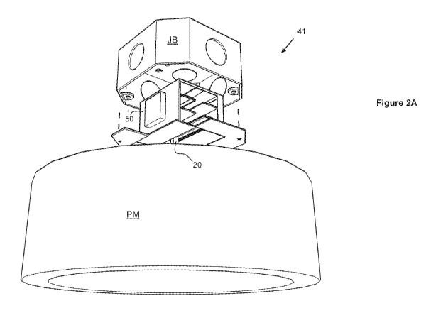
[0010] Figures 2A, 2B, and 2C illustrate perspective views of an exemplary
in-
junction-box system.
[0011] Figure 3 illustrates a perspective view of an exemplary mounting
assembly in
the unlocked position.
[0012] Figure 4 illustrates a perspective view of the exemplary mounting
assembly
of figure 3 from a different orientation.
[0013] Figure 5 illustrates a magnified view of the exemplary mounting
assembly of
figure 4.
[0014] Figure 6 illustrates a magnified view of the exemplary mounting
assembly of
figure 4.
2
CA 03106111 2021-01-08
WO 2020/018870 PCT/US2019/042529
[0015] Figure 7 illustrates a magnified view of the exemplary mounting
assembly of
figure 4.
DETAILED DESCRIPTION
[0016] Track System
[0017] Figures 1A and 1B illustrate perspective views of a system 1 for
mechanical
and electrical engagement of a powered module PM to a ceiling DW. The powered
module PM may be any module that receives power (AC or DC) to operate such as,
for
example, a light fixture, a speaker, a wi-fi router or repeater, a smoke
detector, etc. As
described below, the system 1 provides convenient installation of the powered
module
PM to the ceiling DW. Figure 1A illustrates the system 1 in the inserting
position while
figure 1B illustrates the system 1 in the locked or connected position. The
system 1
includes a track 10 and a mounting assembly 20.
[0018] Track
[0019] The track 10 may include an upper rail 11, electrode rails 12, 13,
and locking
rails 14. The track 10 may also include side walls 15 connecting the upper
rail 11, the
electrode rails 12,13, and the locking rails 14. In the example of figures 1A
and 1B, the
track 10 includes two sets of electrode rails 12, 13. In other embodiments
(not shown),
the track 10 may include one set of electrode rails 12, 13 or more than two
sets of
electrode rails 12, 13.
[0020] The electrode rails 12, 13 may have electrodes 16, 17 coupled or
formed
thereon. The electrodes 16, 17 are elongated conductors (e.g., copper,
aluminum, etc.)
that extend most of the length of the corresponding rail. For example, a first
electrode
rail 12 may have coupled or formed thereon a positive electrode 16 extending
most of
the length of the rail 12 while a second electrode rail 13 may have coupled or
formed
thereon a negative electrode 17 extending most of the length of the rail 13.
In the
example of figures 1A and 1B, each of the electrode rails 12, 13 has one
electrode 16,
17 coupled or formed thereon. In other embodiments (not shown), each of the
electrode
rails 12, 13 may include more than one electrode 16, 17 coupled or formed
thereon.
3
CA 03106111 2021-01-08
WO 2020/018870 PCT/US2019/042529
[0021] In the example of figures 1A and 1B, the first electrode rails 12
have coupled
or formed thereon electrodes 16 on a top surface 12a of the rails 12.
Similarly, in the
example of figures 1A and 1B, the second electrode rails 13 have coupled or
formed
thereon electrodes 17 on a top surface 13a of the rails 13. In other
embodiments (not
shown), the first electrode rails 12 may have coupled or formed thereon
electrodes 16
on a bottom surface 12b of the rails 12 or on both the top surface 12a and
bottom
surface 12b. Similarly, the second electrode rails 13 may have coupled or
formed
thereon electrodes 17 on a bottom surface 13b of the rails 13 or on both the
top surface
13a and bottom surface 13b.
[0022] The track may also include a ground conductor 18 disposed on a
bottom
surface lla of the upper rail 11. Like the electrodes 16, 17, the ground
conductor 18
may be an elongated conductor (e.g., copper, aluminum, etc.) that extends most
of the
length of the upper rail 11. The ground conductor 18 may be installed or
formed near
the center of the bottom surface lla of the upper rail 11.
[0023] The electrodes 16, 17, and the ground conductor 18 may be connected
to a
circuit such as, for example, a power circuit that may include a switch or
dimmer to
operate or control a powered module to be installed to the track 10. The
electrodes 16,
17 may also correspond to, for example, positive and negative signals of an
audio
stereo output, etc.
[0024] The track 10 may also include mounting brackets 19 to attach the
track 10 to,
for example, a ceiling joist or other ceiling structure using bolts or another
type of
fastener. The locking rails 14 may extend outwardly from the walls 15 into
flanges 14a.
The track 10 may be installed substantially flush with a ceiling surface. The
main body
of the track 10 (including the upper rail 11, electrode rails 12, 13, and the
side walls 15)
may be inserted in a channel formed on the ceiling and the flanges 14a may
overlap a
portion of, for example, a drywall board DW which forms part of the ceiling.
[0025] In-Junction-Box System
[0026] Figures 2A-2C illustrate views of an exemplary system 41 for
mechanical and
electrical engagement of a powered module PM to a junction box JB. As
described
above, the powered module PM may be any module that receives power (AC or DC)
to
4
CA 03106111 2021-01-08
WO 2020/018870 PCT/US2019/042529
operate such as, for example, a light fixture, a speaker, a wi-fi router or
repeater, a
smoke detector, etc. As described below, the system 41 provides convenient
installation
of the powered module PM to the junction box JB. For illustrative purposes,
figures 2A
and 2B illustrate the system 41 uninstalled or exploded away from the junction
box JB.
The system 41 includes an in-junction-box assembly 50 and the mounting
assembly 20.
[0027] In-Junction-Box Assembly
[0028] Figure 2C illustrates a perspective view of an exemplary in-junction-
box
assembly 50. The in-junction-box assembly 50 may include an upper rail 11,
electrode
rails 12, 13, and locking rails 14. The in-junction-box assembly 50 may also
include side
walls 15 connecting the upper rail 11, the electrode rails 12,13, and the
locking rails 14.
In the example of figure 2C, the in-junction-box assembly 50 includes two sets
of
electrode rails 12, 13. In other embodiments (not shown), the in-junction-box
assembly
50 may include one set of electrode rails 12, 13 or more than two sets of
electrode rails
12, 13.
[0029] The electrode rails 12, 13 may have electrodes 16, 17 coupled or
formed
thereon. The electrodes 16, 17 are conductors (e.g., copper, aluminum, etc.)
disposed
on the corresponding rail. For example, a first electrode rail 12 may have
coupled or
formed thereon a positive electrode 16 while a second electrode rail 13 may
have
coupled or formed thereon a negative electrode 17. In the example of figure
2C, each of
the electrode rails 12, 13 has one electrode 16, 17 coupled or formed thereon.
In other
embodiments (not shown), each of the electrode rails 12, 13 may include more
than one
electrode 16, 17 coupled or formed thereon.
[0030] In the example of figure 2C, the first electrode rails 12 have
coupled or
formed thereon electrodes 16 on a top surface 12a of the rails 12. Similarly,
in the
example of figure 2C, the second electrode rails 13 have coupled or formed
thereon
electrodes 17 on a top surface 13a of the rails 13. In other embodiments (not
shown),
the first electrode rails 12 may have coupled or formed thereon electrodes 16
on a
bottom surface 12b of the rails 12 or on both the top surface 12a and bottom
surface
12b. Similarly, the second electrode rails 13 may have coupled or formed
thereon
CA 03106111 2021-01-08
WO 2020/018870 PCT/US2019/042529
electrodes 17 on a bottom surface 13b of the rails 13 or on both the top
surface 13a and
bottom surface 13b.
[0031] The in-junction-box assembly 50 may also include a ground conductor
18
disposed on a bottom surface lla of the upper rail 11. Like the electrodes 16,
17, the
ground conductor 18 may be a conductor (e.g., copper, aluminum, etc.) disposed
on the
upper rail 11. The ground conductor 18 may be installed or formed near the
center of
the bottom surface lla of the upper rail 11.
[0032] The electrodes 16, 17, and the ground conductor 18 may be connected
to a
circuit such as, for example, a power circuit that may include a switch or
dimmer to
operate or control a powered module to be installed to the in-junction-box
assembly 50.
The electrodes 16, 17 may also correspond to, for example, positive and
negative
signals of an audio stereo output, etc. In the example of figure 2C, the in-
junction-box
assembly 50 includes electrical terminals 56 and 57 for receiving electrical
wire. The
electrical terminals 56 and 57 may be operably connected to the electrodes 16
and 17,
respectively. In one embodiment, the in-junction-box assembly 50 includes one
or more
ground terminals for receiving electrical wire. The one or more ground
terminals may be
operably connected to the ground conductor 18.
[0033] The in-junction-box assembly 50 may also include mounting brackets
59 to
attach the in-junction-box assembly 50 to the junction box JB. In the
illustrated
embodiment, the mounting brackets 59 are flanges that extend radially away
from a
center axis a of the in-junction-box assembly 50. The mounting brackets 59 may
have
formed thereon mounting holes 60 to mount the in-junction-box assembly 50 to
the
junction box JB. using screws, bolts or another type of fastener. In one
embodiment, the
locking rails 14 may extend outwardly from the walls 15 into the flanges that
form the
mounting brackets 59.
[0034] As shown in figure 2B, the main body of the in-junction-box assembly
50
(including the upper rail 11, electrode rails 12, 13, and the side walls 15)
may be
inserted in the junction box JB and the mounting holes 60 may align with
mounting
holes JBh of the junction box JB. Once the in-junction-box assembly 50 is
inserted in
the junction box JB, the assembly 50 may be secured to the junction box JB
using
6
CA 03106111 2021-01-08
WO 2020/018870 PCT/US2019/042529
screws, bolts or another type of fastener inserted through the mounting holes
60 and
screwed to the holes JBh of the junction box JB. Electrical connections may be
made
using the electrical terminals 56 and 57.
[0035] Mounting Assembly
[0036] Figures 3-7, in addition to figures 1A-2B, illustrate the mounting
assembly 20.
The mounting assembly 20 may be attached to or form part of a powered module
PM.
The mounting assembly 20 provides mechanical and electrical engagement of the
powered module PM to the track 10 or in-junction-box assembly 50 and, thus, to
the
ceiling. The mounting assembly 20 may include a column or stem 21 and a base
22
operably coupled to the powered module PM. In the illustrated embodiment, the
stem
21 has a rectangular cross-section. In other embodiments, the stem 21 may have
cross-
sections different from rectangular such as circular, etc.
[0037] In figure 3 the mounting assembly 20 is shown in a similar position
as in
figure 1A. In figure 4 the mounting assembly 20 is shown rotated about 130
degrees for
illustrative purposes. The mounting assembly 20 may also include electrode
arms 23,
24 extending perpendicularly from the stem 21. Figure 5 illustrates a
magnified view of
the mounting assembly 20 to show details of the electrode arms 23, 24. In
figure 5, the
mounting assembly is in a similar position as in figure 4. In the illustrated
embodiment, a
first electrode arm 23 extends perpendicularly from a first side of the stem
21 while a
second electrode arm 24 extends perpendicularly from an opposite side of the
stem 21.
In the illustrated embodiment, the mounting assembly 20 includes two sets of
electrode
arms 23, 24. In other embodiments (not shown), the mounting assembly 20 may
include
one set of electrode arms 23, 24 or more than two sets of electrode arms 23,
24.
[0038] The electrode arms 23, 24 may have coupled to or formed thereon
electrodes
25, 26. The first electrode 25 is disposed on the first electrode arm 23 to
form or to have
a first incline surface 25a. Similarly, the second electrode 26 is disposed on
the second
electrode arm 24 to form or to have a second incline surface 26a. While in the
illustrated
embodiments, the first and second incline surfaces 25a, 26a are shown as flat
surfaces,
in other embodiments the first and second incline surfaces 25a, 26a may be
curved
surfaces that nonetheless are inclined or ramped. The electrodes 25, 26 are
conductors
7
CA 03106111 2021-01-08
WO 2020/018870 PCT/US2019/042529
(e.g., copper, aluminum, etc.) that extend at least some of the length of the
corresponding electrode arm 23, 24. For example, a first electrode arm 23 may
have
coupled or formed thereon a positive electrode 25 while a second electrode arm
24 may
have coupled or formed thereon a negative electrode 26. In the illustrated
embodiment,
each of the electrode arms 23, 24 has one electrode 25, 26 coupled or formed
thereon.
In other embodiments (not shown), each of the electrode arms 23, 24 may
include more
than one electrode 25, 26 coupled or formed thereon.
[0039] In the illustrated embodiment, the electrodes 25, 26 are coupled or
formed on
the bottom of the electrode arms 23, 24. In other embodiments (not shown), the
electrodes 25, 26 may be coupled or formed on the top of the electrode arms
23, 24 or
on both the top and bottom of the electrode arms 23, 24. The electrodes 25, 26
are
intended to electrically engage the electrodes 16, 17 of the track 10 or in-
junction-box
assembly 50 to provide positive and negative electrical connections,
respectively, to the
powered module PM.
[0040] The mounting assembly 20 may also include locking arms 27, 28
extending
perpendicularly from the stem 21. Figure 6, in addition to figures 1-5,
illustrate the
locking arms 27, 28. Figure 6 illustrates a magnified view of the mounting
assembly 20
to show details of the locking arms 27, 28. In figure 6, the mounting assembly
is a
similar position as in figures 4 and 5. In the illustrated embodiment, a first
locking arm
27 extends perpendicularly from a first side of the stem 21 while a locking
arm 28
extends perpendicularly from an opposite side of the stem 21. The locking arms
27, 28
have formed thereon decline surfaces 27a, 28a. While in the illustrated
embodiments,
the first and second decline surfaces 27a, 28a are shown as flat surfaces, in
other
embodiments the first and second decline surfaces 27a, 28a may be curved
surfaces
that nonetheless are declined or ramped.
[0041] Notice, particularly in figures 1 and 3, that a plane of the first
incline surface
25a intersects a plane of the first decline surface 27a. Similarly, as best
shown in figure
4, a plane of the second incline surface 26a intersects a plane of the second
decline
surface 28a. As described in more detail below, this characteristic of the
incline surfaces
25a, 26a relative to the decline surfaces 27a, 28a allows the mounting
assembly 20 to
8
CA 03106111 2021-01-08
WO 2020/018870 PCT/US2019/042529
be easily insertable in the track 10 or in-junction-box assembly 50 and
securely
mechanically and electrically engageable to the track 10 or in-junction-box
assembly 50.
[0042] The mounting assembly 20 may also include a ground arm 29 extending
from
the top of the stem 21 distal the base 22. Figure 7 illustrates a magnified
view of the
ground arm 29. The ground arm 29 may have coupled or formed thereon a ground
electrode or ground contact 30. The ground contact 30 may be a conductor
(e.g.,
copper, aluminum, etc.) and it is intended to electrically engage the ground
conductor
18 of the track 10 or in-junction-box assembly 50 to provide a ground
connection to the
powered module PM. The ground contact 30 may be elastically connected to the
ground
arm 29 extending from the top of the stem 21. In one embodiment, the mounting
assembly 20 includes a spring disposed between the ground electrode 30 and the
distal
end 29. In other embodiments, the ground contact 30 may be elastically
connected to
the ground arm 29 by other elastic means such as, for example, an elastomer,
etc. In
one embodiment, the ground contact 30 is not elastically connected to the
ground arm
29.
[0043] The mounting assembly 20 may also include electrical connections
(e.g.,
wires, printed circuit board, etc.) to electrically connect the electrodes 25,
26 and the
ground contact 30 to the powered module PW. For example, the mounting assembly
20
may include electrical terminals at or near the base 22 and electrical
connections within
the arms 23 and 24, and the stem 21 that electrically connect the electrodes
25, 26 and
the ground contact 30 to the electrical terminals. Wiring of the powered
module PM may
connect to the electrical terminals of the mounting assembly 20 to power the
powered
module PM.
[0044] Powered Module Installation
[0045] A method of mounting a powered module PM including or having coupled
thereon the mounting assembly 20 to a track 10 or in-junction-box assembly 50
would
be described now in reference to the figures.
[0046] First, a user may insert the stem 21 in the orientation shown in
figure 1A into
the groove or opening G formed between the locking rails 14 and between the
electrode
rails 12, 13. In the illustrated embodiment, inserting the stem 21 into the
groove G until
9
CA 03106111 2021-01-08
WO 2020/018870 PCT/US2019/042529
the ground contact 30 contacts the ground conductor 18 results in the
electrode arms
23, 24 being simultaneously inserted into the groove G while the locking arms
28
remain uninserted into the groove G.
[0047] If using the track system 1, at this point, the user may slide the
powered
module PM to a desired position along the track 10.
[0048] The user may then rotate the powered module PM clockwise for the
incline
surfaces 25a, 26a of the electrodes 25, 26 of the mounting assembly 20 to
engage the
electrodes 16, 17 of the track 10 or in-junction-box assembly 50. In the
illustrated
embodiment, the incline and decline surfaces are disposed such that clockwise
rotation
locks the mounting assembly 20 to the track 10 or in-junction-box assembly 50.
In other
embodiments, the incline and decline surfaces may be disposed such that
counter
clockwise rotation of the powered module PM result in locking of the mounting
assembly
20 to the track 10 or in-junction-box assembly 50. In the illustrated
embodiment, this
clockwise rotation of the powered module PM simultaneously causes engagement
of
the decline surfaces 27a, 28a of the locking arms 27, 28 of the mounting
assembly 20 to
bottom sides 14b of the locking rails 14 of the lighting track 10 or in-
junction-box
assembly 50.
[0049] Simultaneous pressure of the incline surfaces 25a, 26a against the
electrodes
16, 17 and of the decline surfaces 27a, 28a against the bottom sides 14b of
the locking
rails 14 mechanically creates a locking, spring-like, effect of the mounting
assembly 20
to the track 10 or in-junction-box assembly 50. This simultaneous pressure
also
provides adequate electrical connection between the electrodes 25, 26 and the
electrodes 16, 17. In one embodiment, the incline surfaces 25a, 26a and/or the
decline
surfaces 27a, 28a may include a particularly sharp edge to bite into the
electrodes 16,
17 and/or the bottom sides 14b of the locking rails 14, respectively, to
provide an
additional locking effect. Finally, this arrangement results in adequate
electrical
connection between the ground contact 30 and the ground conductor 18,
particularly if
the ground contact 30 is elastically connected to the ground arm 29.
[0050] In one embodiment, the mounting assembly 20 may not include the
locking
arms 27, 28 and, instead, the system 1 may rely on simultaneous pressure of
the incline
CA 03106111 2021-01-08
WO 2020/018870 PCT/US2019/042529
surfaces 25a, 26a against the electrodes 16, 17 and of the ground contact 30
against
the ground conductor 18. In this embodiment, the ground arm 29 acts as a
locking arm
and the ground contact 30 as locking surface. Notice that planes of the
incline surfaces
25a, 26a intersect a plane of the ground contact or locking surface 30
resulting in elastic
repulsive pressure when the mounting assembly 20 is inserted in the groove G
and
rotated clockwise. This elastic repulsive pressure not only results in
adequate electrical
connection between the ground contact 30 and the ground conductor 18 but also
creates a locking spring-like effect of the mounting assembly 20 to the track
10 or in-
junction-box assembly 50. Thus, this simultaneous pressure may also provide
adequate
electrical connection between the electrodes 25, 26 and the electrodes 16, 17.
This
pressure may be particularly controllable in an embodiment in which the ground
contact
30 is elastically (e.g., spring loaded) connected to the ground arm 29. In one
embodiment, the incline surfaces 25a, 26a may include a particularly sharp
edge to bite
into the electrodes 16, 17 to provide an additional locking effect.
[0051] Removal or reinstallation of a powered module PM is just as
convenient. The
user may rotate the powered module in the opposite direction (e.g., counter-
clockwise in
the illustrated embodiment) to disengage the incline surfaces 25a, 26a of the
electrodes
25, 26 of the mounting assembly 20 from the electrodes 16, 17 of the track 10
or in-
junction-box assembly 50. This rotation also disengages the decline surfaces
27a, 28a
from the bottom 14b of the bottom rail 14. The user may rotate the powered
module PM
until the mounting assembly 20 is oriented in the inserted position as shown
in figure
1A. The user may then simply remove the power module PM from the track 10 or
slide
the power module PM to any desired position along the track 10 for
installation at that
new position. Similarly, the user may then simply remove the power module PM
from
the in-junction-box assembly 50.
[0052] DEFINITIONS
[0053] The following includes definitions of selected terms employed
herein. The
definitions include various examples or forms of components that fall within
the scope of
a term and that may be used for implementation. The examples are not intended
to be
limiting. Both singular and plural forms of terms may be within the
definitions.
11
CA 03106111 2021-01-08
WO 2020/018870 PCT/US2019/042529
[0054] As used herein, an "operable connection" or "operable coupling," or
a
connection by which entities are "operably connected" or "operably coupled" is
one in
which the entities are connected in such a way that the entities may perform
as
intended. An operable connection may be a direct connection or an indirect
connection
in which an intermediate entity or entities cooperate or otherwise are part of
the
connection or are in between the operably connected entities. In the context
of signals,
an "operable connection," or a connection by which entities are "operably
connected," is
one in which signals, physical communications, or logical communications may
be sent
or received. Typically, an operable connection includes a physical interface,
an
electrical interface, or a data interface, but it is to be noted that an
operable connection
may include differing combinations of these or other types of connections
sufficient to
allow operable control. For example, two entities can be operably connected by
being
able to communicate signals to each other directly or through one or more
intermediate
entities like a processor, operating system, a logic, software, or other
entity. Logical or
physical communication channels can be used to create an operable connection.
[0055] To the extent that the term "includes" or "including" is employed in
the
detailed description or the claims, it is intended to be inclusive in a manner
similar to the
term "comprising" as that term is interpreted when employed as a transitional
word in a
claim. Furthermore, to the extent that the term "or" is employed in the
detailed
description or claims (e.g., A or B) it is intended to mean "A or B or both".
When the
applicants intend to indicate only A or B but not both" then the term only A
or B but not
both" will be employed. Thus, use of the term "or" herein is the inclusive,
and not the
exclusive use. See, Bryan A. Garner, A Dictionary of Modern Legal Usage 624
(2d. Ed.
1995).
[0056] While example systems, methods, and so on, have been illustrated by
describing examples, and while the examples have been described in
considerable
detail, it is not the intention of the applicants to restrict or in any way
limit scope to such
detail. It is, of course, not possible to describe every conceivable
combination of
components or methodologies for purposes of describing the systems, methods,
and so
on, described herein. Additional advantages and modifications will readily
appear to
those skilled in the art. Therefore, the invention is not limited to the
specific details, the
12
CA 03106111 2021-01-08
WO 2020/018870 PCT/US2019/042529
representative apparatus, and illustrative examples shown and described. Thus,
this
application is intended to embrace alterations, modifications, and variations
that fall
within the scope of the appended claims. Furthermore, the preceding
description is not
meant to limit the scope of the invention. Rather, the scope of the invention
is to be
determined by the appended claims and their equivalents.
13