Note: Descriptions are shown in the official language in which they were submitted.
CA 03106133 2021-01-11
A particle receiving device, arrangement and method for operating an
arrangement
The invention relates to a particle receiving device for attachment to a
particle outlet of a
vacuum cleaner and/or of a cyclone separator and for receiving separated
particles. The particle
receiving device comprises a particle receiving volume for receiving the
particles and an access
element with an access element opening. Particles can be transported into the
particle receiving
volume through the access element opening.
The particle receiving volume is provided for example by way of a bag and/or a
container. The bag and/or the container are expediently fastened to the access
element.
In operation, particles are separated by the vacuum cleaner and/or the cyclone
separator
and are output out of the particle outlet. The particles get into the particle
receiving volume via
the access element and are collected there.
It is an object of the invention to increase the operational safety of the
particle receiving
device.
This object is achieved by the subject-matter according to claim 1. The
particle receiving
device comprises a closure element. The access element is selectively
displaceable relative to the
closure element into a closure position or into an open position. In the
closure position, the
closure element closes access opening. In the open position, the closure
element releases the
access element opening.
By way of bringing the access element into the closure position, the access
element
opening can consequently be closed, so that the probability of particles
getting out of the particle
receiving volume into the environment and contaminating this can be reduced.
The operational
safety can be increased in this manner, in particular when the particles are
particles which are
harmful to health.
In particular, the access element can be brought into the closure position in
a state in
which the particle receiving device is attached to the particle outlet - thus
before a removal of the
particle receiving device from the particle outlet.
Preferably, the access element can be moved directly from the open position,
in which it
is located directly below the particle outlet and in particular directly below
a particle outlet
opening, into the closure position, in which the upper side of the access
element is expediently
located completely below the closure element and is covered by this. The
access element
1
Date Recue/Date Received 2021-01-11
CA 03106133 2021-01-11
opening is expediently always closed in every position of the access element
and/or is located
below the particle outlet opening, so that the risk of a contamination of the
environment is
reduced.
The regions which are contaminated by particles can also be denoted as a black
region or
contamination region and the non-contaminated region as a white region or
clean region. By way
of the closure of the particle receiving device at the particle outlet, the
separation between the
black region and the white region can be improved, and in particular one
succeeds in the black
region of the particle receiving device being closed with respect to the
environment in particular
after the removal from the particle outlet, so that the risk of a
contamination is reduced.
Advantageous further developments are the subject-matter of the dependent
claims.
According to a possible design, the access element comprises an upper side
which in the
open position of the access element represents an outer side of the particle
receiving device and
can be applied onto the particle outlet.
According to a further design, the closure element is arranged on the upper
side of the
access element.
According to a further design, the particle receiving device comprises a bag
and/or a
container for providing the particle receiving volume, wherein the bag and/or
the container is
fastened to the access element and is movable together with the access element
relative to the
closure element.
According to a further design, when the access element is situated in the
closure position,
the closure element completely covers the access element upper side which can
be applied onto
the particle outlet.
According to a further design, the closure element comprises a closure element
coupling
section, with which the closure element can be fastened to the particle
outlet.
The invention further relates to an arrangement comprising a particle
receiving device
which is described here, as well as the particle outlet which comprises a
particle outlet opening,
wherein the particle receiving device is attached to the particle outlet.
According to a possible design, the particle receiving volume is closed with
respect to the
environment in every possible position of the access element relative to the
closure element.
2
Date Recue/Date Received 2021-01-11
CA 03106133 2021-01-11
According to a further design, the particle receiving device is a first
particle receiving
device and the arrangement further comprises a second particle receiving
device with a second
closure element and with a second access element which comprises a second
access element
opening, wherein the second access element can be selectively brought into an
open position or a
closure position, wherein in the closure position the second access element
opening is closed by
the second closure element.
According to a further design, the first access element and the second access
element
together as a group can be selectively brought into a first position or a
second position, wherein
in the first position the first access element is in the open position and the
second access element
in the closure position, and in the second position the first access element
is in the closure
position and the second access element in the open position.
According to a further design, in the first position, the second position and
in all positions
between the first position and the second position, the particle receiving
volumes of the particle
receiving devices and the particle outlet inner volume of the particle outlet
are closed with
respect to the environment.
According to a further design, the particle outlet comprises a closure element
receiving
section which is distanced to the particle outlet opening and the closure
element is located
completely in the closure element receiving section.
According to a further design, the arrangement comprises a blocking mechanism
which
prevents the particle receiving device from being able to be removed from the
particle outlet in a
position other than the closure position.
According to a further design, the arrangement comprises a locking mechanism
which,
depending on whether the particle receiving device is attached to the particle
outlet, locks the
closure element with respect to the access element, wherein in a state in
which the particle
receiving device is removed from the particle outlet, the locking mechanism
locks the access
element in the closure position, and in a state in which the particle
receiving device is attached to
the particle outlet, unlocks the access element, so that it can be brought
into the open position.
The invention further relates to a method for operating an arrangement which
is described
here, comprising the steps:
-
attaching the particle receiving device to the particle outlet, wherein the
access element is
situated in the closure position,
3
Date Recue/Date Received 2021-01-11
CA 03106133 2021-01-11
- bringing the access element into the open position,
- transporting particles into the particle receiving volume,
- bringing the access element into the closure position, wherein the
particle receiving
volume remains closed with respect to the environment,
- removing the particle receiving device from the particle outlet, wherein
the particle
receiving volume is closed with respect to the environment,
According to a preferred design, the method further comprises the steps:
- attaching the first particle receiving device to the particle outlet,
wherein the first access
element is situated in the closure position,
- bringing the first access element into the open position,
- transporting the particles into the first particle receiving volume,
- attaching the second particle receiving device to the particle outlet,
wherein the second
access element is situated in the closure position,
- commonly bringing the first access element into the closure position and
the second
access element into the open position, wherein the particle receiving volumes
are closed
with respect to the environment,
- removing the first particle receiving device from the particle outlet,
wherein the first
particle receiving volume remains closed with respect to the environment.
Exemplary details and preferred embodiments are explained hereinafter with
reference to
the figures. Herein are shown:
Figure 1 a schematic view of an arrangement according to a first
embodiment, comprising
a particle outlet and a particle receiving device,
Figure 2 the arrangement according to the first embodiment, wherein the
particle receiving
device is attached to the particle outlet,
4
Date Recue/Date Received 2021-01-11
CA 03106133 2021-01-11
Figure 3 the arrangement according to the first embodiment, wherein the
access element is
situated in the open position,
Figure 4 an arrangement according to the second embodiment, comprising a
particle outlet
and two particle receiving devices,
Figure 5 the arrangement according to the second embodiment, wherein a
first particle
receiving device is attached to the particle outlet,
Figure 6 the arrangement according to the second embodiment, wherein both
particle
receiving devices are attached to the particle outlet and the access elements
are
situated in a first position,
Figure 7 the arrangement according to the second embodiment, wherein the
access
elements are situated in a second position,
Figure 8 the arrangement according to the second embodiment, wherein the
first particle
receiving device is removed from the particle outlet,
Figure 9 a schematic view of a construction with a cyclone separator and a
suction device,
Figure 10 an exemplary design of the arrangement according to the second
embodiment,
wherein the access elements are situated in the first position,
Figure 11 the design of Figure 10, wherein the access elements are situated
in a second
position,
Figure 12 a sectioned view of the design,
Figure 13 a perspective view from below upon an exemplary design of an
assembly of a
closure element and of an access element,
Figure 14 a perspective view from below upon the access element,
Figure 15 a perspective view from above upon the access element,
Figure 16 a perspective view from below upon the closure element,
Figure 17 a perspective view from above upon the closure element,
Date Recue/Date Received 2021-01-11
CA 03106133 2021-01-11
Figure 18 a perspective view from below upon the particle outlet,
Figure 19 an attachment of the closure element to the particle outlet,
Figure 20 a perspective view of the particle outlet from above.
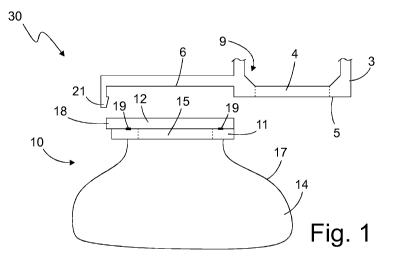
Figures 1 to 3 relate to a first embodiment and show a particle receiving
device 10
together with a particle outlet 3. The particle receiving device 10 can, in
general, also be
provided on its own - thus in particular without the particle outlet 3. The
combination of the
particle receiving device 10 and the particle outlet 3 is denoted as an
arrangement 30.
Figure 1 shows the particle receiving device 10 in a state in which it is
removed from the
particle outlet 3. In the Figures 2 and 3, the particle receiving device 10 is
shown in a state in
which it is attached to the particle outlet 3.
The particle receiving device 10 is designed for attachment onto the particle
outlet 3. The
particle outlet 3 is for example a particle outlet 3 of vacuum cleaner and/or
of a cyclone separator
1. The particle receiving device 10 is designed to receive and in particular
to collect particles
which are separated by a vacuum cleaner and/or a cyclone separator 1 and
output via the particle
outlet 3.
The particle receiving device 10 comprises a particle receiving volume 14 for
receiving
the particles. The particle receiving device 10 further comprises an access
element 11 with an
access element opening 15. The separated particles can be transported into the
particle receiving
volume 14 via the access element opening 15.
Furthermore, the particle receiving device 10 comprises a closure element 12.
The access
element 11 can be selectively brought into a closure position or an open
position relative to the
closure element 12. The closure position is shown for example in Figures 1 and
2 and the open
position in Figure 3. In the closure position, the closure element 12 closes
the access element
opening 15. In the open position, the closure element 12 releases the access
element opening 15.
Hereinafter, further exemplary details and embodiments are discussed. Herein,
the spatial
directions "x", "y", "z" which are drawn in the figures and are aligned
orthogonally to one
another are referred to as the "x-direction, "y-direction" and "z-direction".
Firstly to the access element 11:
6
Date Recue/Date Received 2021-01-11
CA 03106133 2021-01-11
The access element 11 by way of example comprises a plate-shaped access
element
body. The access element 11 comprises a lower side which faces the particle
receiving volume
14 and an upper side which faces the closure element 12 (in the closure
position) and/or the
particle outlet 3. The lower side and the upper side are opposite to one
another and by way of
example are aligned normally to the z-direction. Expediently, the lower side
and the upper side
are each sides of the access element 11 which are largest with regard to
surface area.
The access element 11 comprises the access element opening 15. By way of
example, the
access element opening 15 is an opening from the upper side to the lower side
of the access
element 11. Expediently, the access element opening 15 is circular.
Preferably, the access
element opening 15 assumes at least 40% of the x-y base surface of the access
element 11.
The access element 11 is attached to a bag 17 which encloses the particle
receiving
volume 14. Alternatively to this, the access element can also be attached to a
container. The
access element opening 15 provides an access to the particle receiving volume
14, expediently
the only access to the particle receiving volume 14. The bag 17 or the
container by way of
example is attached to the lower side of the access element 11 and in
particular is permanently
positively and/or in a force-fitting manner connected to the access element
11. The bag 17 or the
container by way of example is connected to the access element 11 by way of a
chemical or
physical connection. In Figures 2 and 3, the bag 17 is not shown completely
for reasons of space.
By way of example, the access element 11 comprises a seal 19 which on the
upper side is
arranged around the access element opening 5. The seal 19 is preferably
annular. If the particle
receiving device 10 is attached to the particle outlet 3 and the access
element 11 is situated in the
closure position, as is shown in Figure 2, then the seal 10 bears on the lower
side of the closure
element 12 and seals the particle receiving volume 14 with respect to the
environment. If the
access element 11 is situated in the closure position, as is shown in Figure
3, then the seal 19
bears on the lower side of the particle outlet 3 and seals a contamination
volume which is formed
from the particle receiving volume 14, the access element opening 15, the
particle outlet opening
4 and the particle outlet inner volume 9, with respect to the environment.
Alternatively or additionally to this, a seal can also be present on the lower
side of the
closure element 12 and/or on the lower side of the particle outlet 3, in order
to provide the one or
both aforementioned sealings with respect to the environment.
Expediently, one, several or all of the mentioned seals are designed as a
labyrinth seal.
The access element 11 by way of example can be displaced in the x-direction
and can
hence be selectively brought into the open position or the closure position.
In Figure 2 (where the
7
Date Recue/Date Received 2021-01-11
CA 03106133 2021-01-11
access element 11 is situated in the closure position), the access element 11
must be displaced for
example to the right, in order to assume the open position.
In a state in which the particle receiving device 10 is attached to the
particle outlet 3, the
access element 11 can preferably be displaced exclusively between the open
position and the
closure position, wherein in every possible displacement position of the
access element 1 the
access element opening 15 is either closed and/or together with the particle
outlet opening 4
provides the access to the particle receiving volume 4. According to a
preferred embodiment, the
access element opening 15 is closed with respect to the environment in every
displacement
position of the access element 11.
Now to the closure element 12:
The closure element 12 comprises a plate-shaped closure element body. The
closure
element 12 comprises a lower side which faces the access element 11 (in the
closure position)
and an oppositely directed upper side. The lower side and the upper side are
preferably the sides
of the closure element 12 which are the largest with regard to surface area.
By way of example,
the lower side and the upper side are aligned normally to the z-direction.
The closure element 12 preferably lies directly on the access element 11 as is
shown in
Figure 1. The closure element 12 and the access element 11 are mounted in
manner in which
they are movable to one another, in particular in the x-direction.
Expediently, the mounting between the closure element 12 and the access
element 11 is
such that the access element 11 cannot be moved relative to the closure
element 12 in the z-
direction. By way of example, the access element 11 is mounted directly on the
closure element
12. For this, suitable guide sections (not shown in Figures 1 to 3) can be
provided, as will yet be
explained hereinafter with reference to the Figures 11 to 20.
The closure element 12 comprises a closure element coupling section 18 with
which the
closure element 12 can be fastened to the particle outlet 3. Expediently, the
closure element 12
can be fastened with the closure element coupling section 18 to the particle
outlet 3 in a manner
such that the closure element 12 is fixed relative to the particle outlet 3 in
all spatial directions.
Preferably, the closure element 12 and/or the access element 11 each have a
rectangular
x-y base surface. Expediently, the size of the x-y base surface of the access
element 11 is at least
75% and/or maximally 125% of the base surface of the closure element 12.
Now to the particle outlet 3:
8
Date Recue/Date Received 2021-01-11
CA 03106133 2021-01-11
The particle outlet 3 by way of example comprises an access element contact
surface 5
which is aligned normally to the z-direction and in which the particle outlet
opening 4 is located.
The particle outlet opening 4 is preferably an opening which runs from the
inner side to an outer
sire of the particle outlet 3. The particle outlet opening 4 by way of example
is circular and
preferably has the same diameter as the access element opening 15.
Expediently, the particle
outlet opening 4 and the access element opening 5 are aligned when the access
element 11 is
situated in the open position. Alternatively, it is also possible for the
particle outlet opening 4 and
the access element opening 15 not to have the same diameter. Preferably, the
particle outlet
opening 4 with regard to surface area is 75% the size of the access element
opening 15 and/or
with regard to surface area is maximally 125% the size of the access element
opening 15.
By way of example, the particle outlet 3 further comprises a closure element
receiving
section 6 which is spaced apart from the particle outlet opening 4 and
expediently connects onto
the access element contact surface 5 in the x-direction. The closure element
receiving section 6 is
designed for receiving and fastening the closure element 12. Preferably, the
closure element 12
remains permanently - thus in particular in the open position and in the
closure position of the
access element 11 - in the closure element receiving section 6 when the
particle receiving device
is fastened to the particle outlet 3. By way of example, the closure element
receiving section 6
comprises a recess in the z-direction (in particular relative to the access
element contact surface
5) for receiving the closure element 12, in particular for receiving its plate-
shaped closure
element body. By way of example, the lower side of the closure element 12 and
the access
element contact surface 5 are located at the same height in the z-direction,
so that the access
element 11 by way of a linear displacement in the x-direction can be moved
between the open
position and the closure position while having permanent bearing contact on
the lower side of the
closure element 12 and/or on the access element contact surface 5.
The closure element 12 is expediently located completely in the closure
element
receiving section 6. In particular, the closure element 12 is located outside
the access element
contact surface 5. The upper side and/or the lateral sides of the closure
element 12 is located in a
clean region - thus a region which is not contaminated by the particles. The
closure element
receiving section 6 can also be denoted as a clean region.
Expediently, the access element 11 in the closure position is likewise
situated completely
outside the access element contact surface 5.
The particle outlet 3 by way of example further comprises a fastening
interface 21, in
order to fasten the closure element 12 to the particle outlet 3. Purely by way
of example, the
fastening interface 21 comprises a latching element which can be brought into
engagement with
9
Date Recue/Date Received 2021-01-11
CA 03106133 2021-01-11
the closure element coupling section 21. By way of example, the latching
element is arranged in
the x-direction on the face side - the outer face side - of the closure
element receiving section 6
said face side facing away from the particle outlet opening 4. The latching
element by way of
example comprises an actuation section which projects in the z-direction and
which can be
actuated in the x-direction, in order to release the engagement with the
closure element coupling
section 18.
The particle outlet 3 further comprises the particle outlet inner volume 9
which is
accessible via the particle outlet opening 4. The particle outlet inner volume
9 for example is part
of a cyclone chamber and/or is in fluidic connection with a cyclone chamber.
Alternatively or
additionally, the particle outlet inner volume 9 can also be part of a fluid
conduit of a vacuum
cleaner and/or be in fluid connection thereto.
The particle outlet 3, in a state in which the closure element 12 is attached
to the access
element 11 and the access element 11 is situated in the open position, is
located over the access
element opening 5, so that the access element opening 15 and the particle
outlet opening 4
together provide the access to the particle receiving volume 14. The particle
receiving volume 14
is herein expediently sealed with respect to the environment.
In particular, the arrangement 30 can be operated as follows:
In an initial state which is shown in Figure 1, the particle receiving device
10 is not
attached to the particle outlet 3. The access element 11 is situated in the
closure position.
The particle receiving device 10 is attached to the particle outlet 3, in
particular by way of
the closure element 12 being fixed to the closure element receiving section 6.
Herein, the access
element 11 continues to be situated in the closure position. Expediently, the
particle receiving
device 10 can only be attached to the particle outlet 3 in the closure
position. The access element
opening 5 expediently always remains closed on attachment. The attached
particle receiving
device is shown in Figure 2.
The access element 11 is then brought into the open position 11, for example
by way of
the displacement of the access element 11 relative to the closure element 12
and to the particle
outlet 3. The access element in the open position is shown in Figure 3.
Particles are subsequently transported out of the particle outlet inner volume
9 into the
particle receiving volume 4 via the particle outlet opening 4 and the access
element opening 15.
In particular, this is effected by way of gravitational force and/or by way of
negative pressure, in
particular an airflow.
Date Recue/Date Received 2021-01-11
CA 03106133 2021-01-11
The access element 11 is then brought into the closure position, for example
by way of a
displacement of the access element 11 relative to the closure element 12 and
to the particle outlet
3. The arrangement 30 is therefore again situated in the state which is shown
in Figure 2.
Finally, the particle receiving device 10 is removed from the particle outlet
3. The access
element opening 5 preferably always remains closed given a removal from the
particle outlet 3.
Preferably, all regions of the particle receiving device 10 which are
contaminated with particles
are closed and/or covered with respect to the environment.
A second embodiment is to be discussed hereinafter with reference to the
Figures 4 to 8.
For reasons of space, the bags 17a, 17b are not completely shown in the
Figures 5 to 8.
The second embodiment is a further development of the first embodiment. The
aforementioned explanations concerning the first embodiment expediently also
apply to the
second embodiment. In particular, the features which are provided with a
reference numeral
which ends with "a" or "b" are designed in accordance with the above features
which are
provided with the corresponding reference numerals without "a" or "b".
Hence the particle receiving device 10 which is described previously, in the
context of
the second embodiment is denoted as a first particle receiving device 10a. The
access element 11
is to be denoted as a first access element 1 la and the closure element 12 as
a first closure element
12a.
Figure 4 shows an arrangement 40 according to the second embodiment. The
arrangement 40 comprises the particle outlet 3, the first particle receiving
device 10a as well as a
second particle receiving device 10b.
The second particle receiving device 10b is expediently designed in accordance
with the
first particle receiving device 10a, preferably is identical to it. The second
particle receiving
device 10b comprises a second closure element 12b and a second access element
1 lb which
comprises a second access element opening 15b. The second access element 1 la
can be
selectively brought into an open position or a closure position. In the
closure position, the second
access element opening 15b is closed by the second closure element 12b. In the
release position,
the second closure element 12b releases the second access element opening 15b.
The particle outlet 3 according to the second embodiment is designed in manner
such that
the first particle receiving device 10a and the second particle receiving
device 10b can be
simultaneously fastened to the particle outlet 3. The particle outlet 3 hence
comprises a first
11
Date Recue/Date Received 2021-01-11
CA 03106133 2021-01-11
closure element receiving section 6a and a first closure element fastening
interface 21a for
receiving and fastening the first closure element 12a. Additionally to this,
the particle outlet 3
comprises a second closure element receiving section 6b and a second closure
element fastening
interface 2 lb for receiving and fastening the second closure element 12b.
The first closure element receiving section 6a and the second closure element
receiving
section 6b are expediently arranged in the x-direction on opposite sides of
the particle outlet 3.
Expediently, the particle outlet 3 is designed in a minor-symmetrical manner
relative to a y-z-
plane which intersects the particle outlet 3. Preferably, the first particle
receiving device 10a is
identical and/or minor-symmetrical to the second particle receiving device
10b.
A state in which both particle receiving devices 10a, 10b are attached to the
particle
outlet 3 is shown in Figure 4. The first access element 1 la is situated in
the open position and the
second access element 1 lb is situated in the closure position. Expediently,
the first access
element 1 la and the second access element 1 lb bear on one another with their
face sides,
wherein the second access element 1 lb connects onto the first access element
1 la in the x-
direction.
The first access element 1 la and the second access element 1 lb together as a
group can
be selectively brought into a first position or into a second position, in
particular by way of a
linear movement in the x-direction. The group of the first access element 1 la
and the second
access element 1 lb are hereinafter to also be denoted as the first group.
This first group can be
displaced relative to a second group comprising the particle outlet 3, the
first closure element 12a
and the second closure element 12b, in order to selectively assume the first
position or the second
position.
The first position is shown in Figure 6 and the second position in Figure 7.
In the first
position, the first access element 1 la is in the open position and the second
access element 1 lb is
in the closure position. The particle outlet opening 4 is located over the
first access element
opening 15a and together with this provides an access to the first particle
receiving volume 14a.
The second access element opening 15b is closed by the second closure element
12b.
In the second position, the first access element 1 la is in the closure
position and the
second access element 1 lb is in the open position. The first access element
opening 15a is closed
by the first closure element 12a. The particle outlet opening 4 is located
over the second access
element opening 15b and together with this provides an access to the second
particle receiving
volume 14b.
12
Date Recue/Date Received 2021-01-11
CA 03106133 2021-01-11
The arrangement 40 in particular is designed in a manner such that in every
possible
displacement position of the first group - of the access elements 11a, 1 lb -
the arrangement 40 is
situated in a state in which each of the access element openings 15a, 15b and
the particle outlet
opening 4 are always closed with respect to the environment. In particular,
this applies to the first
position, the second position and every possible intermediate position.
Expediently, the black
region - thus the contamination region - of the arrangement 40 is always
closed with respect to
the environment. In particular, the arrangement 40 can be brought from the
first position into the
second position without the access element openings 15a, 15b and the particle
outlet opening 4
being released with respect to the environment. The access element openings
15a, 15b are always
closed with respect to the environment by way of the closure elements 12a, 12b
and/or the
particle outlet opening 4, and the particle outlet opening 4 is always closed
with respect to the
environment by way of the access elements 11a, 1 lb in particular the access
element openings
15a, 15b.
On operation, in particular it is possible to change from one particle
receiving volume
14a, 14b to the other particle receiving volume 14a, 14b without herein a
region which is
contaminated by particles ¨ thus in particular the two particle capture
volumes 14a, 14b, the
access element openings 15a, 15b, the particle outlet opening 4 and/or the
inner volume 9 of the
particle outlet 3 - being opened with respect to the environment of the
arrangement 40.
In particular, the arrangement 40 can be operated according to the
subsequently described
method:
Firstly, the first particle receiving device 10a is attached to the particle
outlet 3. The first
access element 1 la is herein situated in the closure position. The first
access element 1 la is then
brought into the open position, so that the arrangement 40 assumes the state
which is shown in
Figure 5. Particles are subsequently transported into the first particle
receiving volume 14a.
Next, the second particle receiving device 10b is attached to the particle
outlet 3. Herein,
the second access element 1 lb is situated in the closure position. The
attachment of the second
particle receiving device 10b can already be effected at an earlier point in
time, e.g. when the
first particle receiving device 10a is attached or already before this.
Next, a common bringing of the first access element 1 la into the closure
position and of
the second access element 1 lb into the open position is effected. The two
access elements 1 la
and 1 lb herein expediently bear on one another. The particle receiving
volumes 14a, 14b and the
particle outlet inner volume 9 remain closed with respect to the environment.
13
Date Recue/Date Received 2021-01-11
CA 03106133 2021-01-11
Finally, the first particle receiving device 10a is removed from the particle
outlet 3,
wherein the particle receiving volumes 14a, 14b and the particle outlet inner
volume 9 continue
to remain closed with respect to the environment.
Figure 9 shows an exemplary application for the arrangement 30 or the
arrangement 40.
The arrangement 30, 40 here is applied within a construction 50. The
construction 50 comprises
a cyclone separator 1, a container 2 and a suction device 22 with a container
receiver 23.
The cyclone separator 1 is applied onto the container 2. The cyclone separator
1 by way
of example is box-shaped and at its upper side expediently comprises a carrier
handle 38. The
particle outlet 3 is arranged on the lower side of the cyclone separator 1.
Expediently, the particle
outlet 3 can be removed from the cyclone separator 1, so that the cyclone
separator 1 can be
operated selectively with the bag 17 or without the bag 17. In the latter
case, the particles are
brought out into the container 2 in a direct manner and are collected there.
The bag 17 is located
in the container 2. The container 2 is inserted into the container receiver 23
which is located on
the upper side of the suction device 22. The suction device 22 preferably
comprises wheels 39
with which it can be supported and moved relative to the floor.
In particular, the suction device 22 is designed to provide a negative
pressure for the
cyclone separator 1, by way of which negative pressure an airflow with
particles can be sucked
into the cyclone separator 1. The suction device 22 is fluidically connected
to the cyclone
separator 1 via a fluidic conduit 24, for example a flexible tube, in order to
provide the negative
pressure. In particular, the fluidic conduit 24 is connected to an air outlet
25 of the cyclone
separator 1.
The cyclone separator 1 further comprises an air inlet 26 on which by way of
example a
suction flexible tube 27 with a suction head 28 is connected. If a negative
pressure is provided at
the air outlet 26, for example by way of the suction device 22, then an
airflow with particles is
sucked through the suction head 28 and the suction flexible tube 27 into the
cyclone separator 1.
There, the airflow with the particles runs through a feed conduit 32 which is
arranged in the
cyclone separator 1 and which leads from the air inlet 26 to a cyclone chamber
33 which is
arranged in the cyclone separator 1. The cyclone chamber 33 is designed
according to the known
functioning principle of a cyclone separator or an centrifugal force
separator, in order to separate
a part of the particles from the airflow. In particular, the cyclone chamber
33 is designed in a
manner such that the airflow is steered onto a circular path, wherein a part
of the particles which
are contained in the airflow are flung onto the walls of the cyclone chamber
33 by way of the
centrifugal force, so that they are braked and are finally output downwards
out of the particle
outlet 3.
14
Date Regue/Date Received 2021-01-11
CA 03106133 2021-01-11
The particles which are output out of the particle outlet 3 are collected in
the bag 17. By
way of example, the bag 17 is sealed, in particular in a particle-tight
manner, preferably in an
airtight manner, via the seal 19.
The airflow is further transported out of the cyclone chamber 33 to the air
outlet 25 via a
discharge conduit 34 which is located in the cyclone separator 1. By way of
example, the airflow
is transported through the fluidic conduit 24 into the suction device 22 and
there in particular
runs through a separating device 25, for example a filter, at which particles
which remain in the
airflow are separated away. The separated particles are collected in a
particle collection volume
36 of the suction device 22, for example in a suction bag. The airflow then
runs through a suction
unit 37, for example a fan, which is present in the suction device and with
which the negative
pressure is produced.
Accordingly, the cyclone separator 1 is fluidically connected upstream of the
suction
device 22 - thus is expediently operated as a preliminary separating stage -
so that the airflow
which is sucked by the suction device 22 has run through the cyclone separator
1 when the
airflow reaches the suction device 21.
Hereinafter, further designs of the aforementioned particle receiving devices
10a, 10b, the
particle outlet 3 and the arrangement 40 are explained with reference to the
Figures 10 to 20. The
bags 17a, 17b are not shown for reasons of an improved representation.
Firstly to the particle outlet 3 which in particular is shown in Figures 18
and 20.
The particle outlet 3 by way of example comprises a particle outlet body 41
which is
expediently designed in a round, in particular bowl-like and/or funnel-like
manner. The upper
side of the particle outlet body 41 is expediently open, as is to be seen in
Figure 20. The access
element contact surface 5 and the particle outlet opening 5 which is located
therein are arranged
on the lower side of the particle outlet body 41. By way of example, the
particle outlet opening 5
is arranged centrally, in particular concentrically on the particle outlet
body 41.
The particle outlet 3 on its lower side comprises a displacement path section
which
extends in the x-direction, is expediently elongate, in particular rectangular
and serves for
attaching the particle receiving devices 10a, 10b and the linearly movable
mounting of the access
elements 11a, 11b. The displacement path section is formed by the in
particular rectangular
access element contact surface 5 as well as the closure element receiving
sections 6a and 6b
which connect onto the access element contact surface 5 in the x-direction at
both sides. The
closure element receiving sections 6a and 6b extend in the x-direction and by
way of example
project from the funnel-like particle outlet body 41.
Date Recue/Date Received 2021-01-11
CA 03106133 2021-01-11
By way of example, fastening sections 42 with which the particle outlet can be
fastened
onto the lower side of the cyclone separator 1 are present on the upper side
of the particle outlet
3. The fastening sections 42 by way of example are arranged in a manner in
which they are
distributed peripherally around the particle outlet body 41. The fastening
sections 42 by way of
example are designed as radial projections and comprise holes into which
screws for example
can be inserted.
The particle outlet 3 on its lower side, in particular on the displacement
path section
comprises fastening interfaces 21a, 2 lb for the particle receiving devices
10a, 10b. The fastening
interfaces 21a, 21b serve for fastening the particle receiving devices 10a,
10b to the particle
outlet 3 in a removable manner, in particular removable in a tool-free manner.
The subsequent explanation relates to the fastening interface 21a, but in a
corresponding
manner also applies to the fastening interface 2 lb.
The fastening interface 21a expediently comprises a first coupling section 51a
and a
second coupling section 52a. The particle receiving device 10a, in particular
the closure element
12a, as is shown in Figure 19, is firstly attachable to the first coupling
section 51a and then in a
state in which it is attached to the first coupling section 51a can be
attached onto the second
coupling section 52a by way of a pivoting movement.
The first coupling section 51a expediently comprises two suspension slots and
is
preferably arranged on the two longitudinal sides of the closure element
receiving section 6a
which run in the x-direction, in particular in the region of the inner face
side of the closure
element receiving section 6a. The suspension slots by way of example are
present on two side
walls 47 which run in the x-direction, and the suspension slots expediently
have an bent course.
The second coupling section 52a expediently comprises a latching element and
is
preferably arranged in the region of the outer face side of the closure
element receiving section
6a. By way of example, the second coupling section 52a is arranged centrally
in the y-direction.
The latching element extends downwards in the z-direction and comprises a
latching element
actuation section which can be actuated in the x-direction, for example by a
finger, in order to
release the coupling of the second coupling section 52a.
The particle outlet 3 comprises the closure element contact surfaces 43a, 43b
on which
the closure elements 12a, 12b bear in the state attached to the particle
outlet 3. The closure
element contact surfaces 43a, 43b are arranged on both sides of the access
element contact
surface 5 in the x-direction. The closure element contact surfaces 43a, 43b
are offset inwards in
16
Date Recue/Date Received 2021-01-11
CA 03106133 2021-01-11
the z-direction relative to the access element contact surface 5, so that a
deepening for receiving
the closure elements 12a, 12b is present.
The particle outlet 3 comprises locking structures 53a, 53b which serve for
locking the
access elements 11a, 1 lb in the open position. The locking structures 53a,
53b by way of
example are arranged between the access element contact surface 5 and the
closure element
contact surfaces 43a, 43b and each comprise an elongate projection which runs
in the y-direction.
The particle outlet 3 further comprises unlocking structures 48a, 48b which
serve for
unlocking the access elements 11a, 1 lb relative to the closure elements 12a,
12b when the
particle receiving devices 10a, 10b are fastened to the particle outlet 3. By
way of example, the
unlocking structures 48a, 48b comprise projections which are arranged on the
closure element
contact surfaces 43a, 43b and project in the z-direction. Expediently, two
elongate projections
which run parallel to one another in the x-direction are present per unlocking
structure 48a, 48b.
The particle outlet 3 further comprises particle outlet guide sections 44
which project
away from the lower side in the z-direction. The particle outlet guide
sections 44 are arranged on
the two longitudinal sides of the access element contact surface 5 and run in
the x-direction. In
the y-direction, the particle outlet opening 4 is located between the particle
outlet guide sections
44. The particle outlet guide sections 44 each comprise a spring element 45.
Guide slots 46 for
the linearly movable guiding of the access element 11a, 1 lb are present
between the spring
element 45 and the access element contact surface.
The closure element 12a is to be dealt with in more detail hereinafter.
Expediently, the
closure element 12b is designed identically to the closure element 12a.
The closure element 12a is shown in Figures 16 and 17. The closure element 12a
comprises a plate-shaped closure element body 62a which in particular is
rectangular. Two
closure element guide sections 61 project downwards away from the closure
element body 62a in
the z-direction. The closure element guide sections 61a are arranged on the
two longitudinal
sides of the closure element body 62a and run in the x-direction. The closure
element guide
sections 61a each comprise a spring element 63a. Guide slots 64a for the
linearly movable
guidance of the access element 11 a are present between the spring element 63a
and the closure
element body 62a of the closure element 12a.
The closure element 12a further comprises guide webs 65a which project inwards
in the
y-direction, by way of example are arranged on the closure element guide
sections 61a and run in
the x-direction.
17
Date Recue/Date Received 2021-01-11
CA 03106133 2021-01-11
The closure element 12a further comprises first stops 66a which by way of
example are
arranged in the region of the inner face side (facing the particle outlet
opening 4) of the closure
element 12a, and second stops which by way of example are arranged in the
region of the outer
face side (facing away from the particle outlet opening 4) of the closure
element 12. The first and
the second stops 66a, 67a by way of example are arranged at the same height in
the z-direction as
the guide webs 65a. By way of example, recesses 76a are formed between the
guide webs 65a
and each of the stops 66a, 67a.
Furthermore, by way of example the closure element 12a comprises a closure
element
seal 68a which is arranged on the closure element body 62a and is preferably
circular. The
closure element seal 68a for example is designed as a labyrinth seal.
The closure element 12a further comprises a locking structure 69a which serves
for
locking the access element 1 la in the closure position relative to the
closure element 12a. The
locking structure 69a comprises at least one projection which projects away
from the base body
62a in the z-direction. By way of example, the locking structure 69a comprises
two pin sections
which project in the z-direction. Alternatively or additionally, the locking
structure 69a can also
comprise further projections, in particular a projection which can be brought
into engagement
with the access element opening 15a, for example a circular projection which
can be expediently
arranged within the closure element seal 68a.
The closure element 12a further comprises an unlocking structure 71a which
contributes
to the unlocking of the access element 1 la relative to the closure element
12a. The unlocking
structure 71a comprises at least one opening, through which the unlocking
structure 48 of the
particle outlet 3 can engage, in order to actuate the access element 1 la and
thus to unlock it. By
way of example, the unlocking structure 71a comprises two elongate unlocking
slots which run
in the x-direction.
The closure element 12a further comprises coupling sections 18a for fastening
the closure
element 12 to the particle outlet 3, in particular to the particle outlet
fastening interface 21a. The
coupling sections expediently comprise first coupling sections 73a and second
coupling sections
74a. The first coupling sections 73 by way of example are designed as pins
which project
outwards in the y-direction. The second coupling section 74a by way of example
is an edge
region of the (outer) faces side of the closure element 12a which is facing
away from the particle
outlet opening 4. Actuation sections 75 with which the closure element 12a can
be pressed in the
z-direction against the second coupling section 52a of the particle outlet 3,
so that the second
coupling section 74a of the closure element 12a latches into the second
coupling section 52a of
the particle outlet 3 are arranged on the second coupling section 74.
18
Date Recue/Date Received 2021-01-11
CA 03106133 2021-01-11
Hereinafter, the access element 1 la which in particular is shown in Figures
14 and 15
will be dealt with. The access element 1 lb is expediently designed
identically to the access
element 1 la.
The access element 11 a comprises a plate-shaped access element body 91a which
by way
of example is rectangular. The access element opening 15a is arranged in the
access element
body 91a. Expediently, an access element seal 92a which is designed for
example as a labyrinth
seal is arranged around the access element opening 15a.
The access element lla comprises a first locking structure 93a which can be
brought into
engagement with the locking structure 69a of the closure element 12a, in order
to lock the access
element 1 la relative to the closure element 12a in the closure position. By
way of example, the
first locking structure 93a comprises two recesses which are present on the
access element body
91a and which by way of example are circular.
The access element lla further comprises a second locking structure 94a which
can be
brought into engagement with the locking structure 53 of the particle outlet
3, in order to lock the
access element 1 la in the open position. By way of example, the second
locking structure 94a
comprises a groove which runs in the y-direction and which is arranged in the
region of the
(outer) face side of the access element 1 la which is facing away from the
particle outlet opening
3.
The access element 1 la further comprises an actuation section 95a which can
be actuated
in the x-direction by the user, in order to move the access element 1 la in
the x-direction. The
actuation section 95a by way of example is designed as a wall-shaped
projection which projects
away from the access element body 91a in the z-direction and which is arranged
on the (outer)
face side of the access element 1 la which is facing away from the particle
outlet opening 3. By
way of example, the actuation section 95a runs in they-direction.
The access element 1 la further comprises a contact web 96a which can be
brought into
bearing contact on the corresponding contact web 96b of the access element 1
lb. The contact
web 96a projects away from the base body 91a in the z-direction and runs in
the y-direction. The
contact web is arranged on the (inner) face side of the access element 1 la
which faces the
particle outlet opening 3.
Furthermore, the access element lla comprises one or more projections 97a
which can
be brought into bearing contact with the first and/or second stops 66a, 67a of
the closure element
12a which have been mentioned above, in order to limit the movement of the
access element 1 la
in the x-direction. By way of example, the projections 97a are arranged
laterally on the actuation
19
Date Recue/Date Received 2021-01-11
CA 03106133 2021-01-11
section 95a and project outwards in the y-direction. The projections 97a by
way of example are
designed in a pin-like manner. The projections are arranged in the region of
the outer face side of
the closure element 1 la.
The access element 1 la further comprises guide sections 98a which can be
brought into
engagement with the guide sections 61a of the closure element 12a and/or the
guide sections 44
of the particle outlet 3, in order to provide the linearly movable mounting of
the access element
1 la. The guide sections 98a by way of example are the longitudinal-side edges
of the plate-
shaped access element body 91a.
In Figure 13, the access element ha is shown together with the closure element
12a. The
access element ha is in the closure position and by way of example is located
completely in the
x-y region which is spanned by the closure element 12a. The assembly of the
access element 1 la
and the closure element 12a can also be denoted as a closure device.
The access element 1 la, 11b, the closure element 12a, 12b and/or the particle
outlet 3 are
expediently single-piece parts, in particular parts which are manufactured in
the original shape as
one piece. For example, the access element 11a, 1 lb, the closure element 12a,
12b and/or the
particle outlet 3 can each be an injection molded part.
Hereinafter, the linearly movable mounting of the access elements 11a, 1 lb on
the
closure elements 12a, 12b and on the particle outlet 3 is dealt with in more
detail. In particular,
Figure 10 is referred to. The subsequent explanation is made on the basis of
the first particle
receiving device 10a and in a corresponding manner applies to the second
particle receiving
device 10b.
The closure element guide section 61a and the particle outlet guide section 44
are
designed to mount the access element 1 la in a lineally movable manner in the
x-direction and in
particular to limit and/or block a movement of the access element 1 la in the
z-direction. The
closure element guide section 61a and the particle outlet guide section 44
extend in the x-
direction and are preferably arranged in the region of the longitudinal sides
of the displacement
path section which run in the x-direction. The closure element guide section
61a and the particle
outlet guide section 44 are expediently arranged one after the other in the x-
direction and are
designed to each cooperate with the same access element guide section 98a, in
order to provide a
linearly movable mounting. By way of example, the side regions of the plate-
shaped access
element body 1 ha which run in the x-direction serve as an access element
guide section 98a.
The closure element guide section 61a and the particle outlet guide section 44
by way of
example each provide guide slots 46, 64a which run in the x-direction and into
which the access
Date Recue/Date Received 2021-01-11
CA 03106133 2021-01-11
element guide section 98a is inserted. The access element 1 la is pressed
against the closure
element 12a and/or the particle outlet 3 by way of the spring elements 45, 63.
By way of displacement in the x-direction, the access element 1 la can be
brought from
the closure position in which with its guide section 98a it is only in
engagement with the guide
section 61a of the closure element 12a, via an intermediate position in which
the access element
ha with its guide section 98a is in engagement with the guide section 61a of
the closure element
12a and the guide section 44 of the particle outlet 3, into the open position
in which the access
element 1 la with its guide section 98a is only in engagement with the guide
section 44 of the
particle outlet 3.
By way of the linearly movable mounting, the access elements 1 la, 1 lb in
particular
together can be selectively brought into the aforementioned first position or
second position.
Figure 10 shows the access elements 1 la, 1 lb in the second position and
Figure 11 shows the
access elements 1 la, 1 lb in the first position.
A blocking mechanism with be dealt with hereinafter, in particular with
reference to
Figure 12.
Expediently, the arrangement 30, 40 comprises a blocking mechanism which
prevents the
particle receiving device 10a, 10b from being able to be removed from the
particle outlet 3 in a
position other than the closure position. A particle receiving device 10a, 10b
can preferably only
be removed if the respective access element 11a, llb is situated in the
closure position. This by
way of example is achieved by way of the access element 11a, 1 lb, when it is
moved out of the
closure position, being brought relative to the particle outlet 3 into a
mounting which prevents a
removal movement which is necessary for the removal of the respective particle
receiving device
10a, 10b.
The blocking mechanism is hereinafter explained by way of the first particle
receiving
device 10a; expediently the blocking mechanism can be present for the second
particle receiving
device 10b in a corresponding manner.
By way of example, the blocking mechanism is formed by the particle outlet
guide
sections 44, the closure element 12a, the access element 11 a and the
fastening interface 21a. As
is shown in Figure 12, the access element 1 la overlaps the closure element
12a in the z-direction
in a state in which the access element 1 la is not situated in the closure
position. In particular, this
state is the open position. Expediently, the outer face side of the access
element 1 la overlaps the
inner face side of the closure element 12a.
21
Date Recue/Date Received 2021-01-11
CA 03106133 2021-01-11
Furthermore, the access element 11 a in the state in which the access element
11 a is not
situated in the closure position, is in engagement with the particle outlet
guide sections 44.
The fastening interface 21a, in particular the first coupling section 51a,
preferably the
suspension slots, are now designed in a manner such that for removal of the
closure element 12a
from the first coupling section 51a, a removal movement is necessary, which is
not possible due
to the overlapping of the access element 1 la with the closure element 12a and
the engagement of
the access element 1 la with the particle outlet guide section 44. In
particular, this is achieved by
way of a pivoting movement firstly being necessary (on account of the second
coupling section
52a) and then, on account of the bent course of the suspension slots, a
movement firstly in the x-
direction and then in the z-direction being necessary, for the removal of the
closure element 12a.
If the access element 1 la is situated outside the closure position, in
particular in the open
position, then expediently at least one of these movements is not possible, so
that overall no
removal of the particle receiving device 10a is possible.
It is therefore ensured that for removal of the particle receiving device 10a,
the access
element 1 la must necessarily be brought into the closure position.
A locking mechanism is to be dealt with hereinafter.
The arrangement 30, 40 by way of example comprises a locking mechanism which
locks
the closure element 12 with respect to the access element 11 depending on
whether the particle
receiving device 10 is attached to the particle outlet 3. In a state in which
the particle receiving
device 10 is removed from the particle outlet 3, the locking mechanism locks
the access element
11 in the closure position. In a state in which the particle receiving device
10 is attached to the
particle outlet, the locking mechanism unlocks the access element, so that it
can be brought into
the open position.
In particular, a displacement of the access element 11 in the x-direction with
respect to
the closure element 12 can be blocked by way of the locking mechanism.
An exemplary design of the locking mechanism is hereinafter explained by way
of the
first particle receiving device 10a. Expediently, the locking mechanism is
also present for the
second particle receiving device 10b in a manner corresponding to this.
The locking mechanism by way of example is formed by the locking structure 69
of the
closure elements 12a, of the spring element 63 of the closure element 12a and
the first locking
structure 93a of the access element 11 a.
22
Date Recue/Date Received 2021-01-11
CA 03106133 2021-01-11
If the access element 1 1 a is in the closure position and the particle
receiving device 10a is
removed from the particle outlet 3, then the locking structure 69 of the
closure element 12a is in
engagement with the first locking structure 93a of the access element 11a and
blocks a
movement of the access element 1 la relative to the closure element 12a in the
x-direction. In
particular, the pin sections of the closure element 12a engage into the
recesses of the access
element 11 a. In order to release the engagement of the locking structure 69
with the locking
structure 93a, by way of example a movement of the access element 1 la
relative to the closure
element 12a in the z-direction is necessary, and specifically counter to the
spring force of the
spring element 63 which presses the access element 1 la against the closure
element 12a in the z-
direction.
The locking mechanism by way of example further comprises the unlocking
structure
48a of the particle outlet 3 as well as the unlocking structure 71 of the
closure element 12a.
If the closure element 12a is attached to the particle outlet 3, then the
unlocking structure
48a the engages through the unlocking structure 71 of the closure element 12a
and presses the
access element 1 la away from the closure element 12a in the z-direction, so
that the engagement
of the locking structures 69, 93a is released. The access element ha in this
state can be moved
out of the closure position by way of actuation in the x-direction.
The locking mechanism expediently further comprises the guide web 65a and the
recess
76a of the closure element 12a as well as projections 97a of the access
element 11a. In the open
position of the access element 1 la, the projections 97a are expediently
located in the recesses
76a between the first stops 66a and the guide webs 65a. By way of example, the
guide webs 65a
comprise a sloped and/or rounded end region, by way of which the access
element 1 la given a
movement towards the closure position is moved away from the closure element
12a in the z-
direction, so that the access element 1 la can be moved over the locking
structure 69a.
A further locking mechanism is to be described hereinafter. This locking
mechanism
locks the access element 1 la in the open position. Expediently, a
corresponding locking
mechanism is present for the access element 12b.
The further locking mechanism by way of example comprises the locking
structure 53 of
the particle outlet 3 and the second locking structure 94a of the access
element 1 la. In the open
position, the locking structure 53 engages into the locking structure 94a so
that it firstly requires
a movement in the z-direction, in order to release this engagement and to move
the access
element 1 la in the x-direction towards the closure position. The engagement
of the locking
structures 53, 94a is to be seen in Figure 12.
23
Date Recue/Date Received 2021-01-11
CA 03106133 2021-01-11
The limitation of the movement of the access element 1 la in the x-direction
is to be
described hereinafter. For this, the first stops 66a and the second stops 67a
are present. In the
open position, the projections 97a of the access element 1 la bear on the
first stops 66a, so that
the access element 1 la cannot be moved further in the x-direction in the
direction away from the
closure position. In the closure position, the projections 97a of the access
element 1 1 a bear on the
second stops 67a, so that the access element 11 a cannot be moved further in
the x-direction in the
direction away from the open position.
Expediently, a corresponding limitation also takes place for the access
element 1 lb.
24
Date Recue/Date Received 2021-01-11