Note: Descriptions are shown in the official language in which they were submitted.
CA 03106300 2021-01-06
WO 2020/047028
PCT/US2019/048459
AXLE-TO-BEAM CONNECTION FOR HEAVY-DUTY VEHICLES
CROSS-REFERENCE TO RELATED APPLICATION
This application claims the benefit of U.S. Provisional Patent Application No.
62/724,719,
filed August 30, 2018.
BACKGROUND OF THE INVENTION
FIELD OF THE INVENTION
The disclosed subject matter is directed to axle/suspension systems for heavy-
duty vehicles.
In particular, the subject matter is directed to axle-to-beam connections for
heavy-duty vehicle
axle/suspension systems. More particularly, the subject matter is directed to
an axle-to-beam
connection, which utilizes a top pad including a structure that acts as a
mechanical bump stop that
prevents potential damage to the beam, axle, and/or components of the axle-to-
beam connection
during jounce events and decreases complexity and manufacturing costs of the
axle/suspension
system. The axle-to-beam connection of the disclosed subject matter utilizes a
window weld
located in the top pad to attach the axle to the beam of each suspension
assembly of the
axle/suspension system and utilizes a structure which minimizes stress on the
axle, thereby
eliminating line welds on the axle and providing a stronger, more resilient
axle-to-beam connection.
Furthermore, the axle-to-beam connection utilizes an alignment assembly
removably connected to
the top pad and attached to or integrated into each beam, enabling separate
shipment of the axle and
1
CA 03106300 2021-01-06
WO 2020/047028
PCT/US2019/048459
suspension assembly and accurate alignment of the axle with the beam and
facilitating quick and
simplified on-site attachment without the need for welding equipment.
BACKGROUND ART
The use of air ride axle/suspension systems in the heavy-duty vehicle industry
is known.
For purposes of convenience and clarity, reference shall be made generally
throughout to a heavy-
duty vehicle with the understanding that such reference includes trucks,
tractor-trailers and semi-
trailers, trailers, and the like. Although axle/suspension systems can be
found in widely varying
structural forms, in general their structure is similar in that each system
typically includes a pair of
suspension assemblies. The suspension assemblies are typically connected
directly to the primary
frame of the heavy-duty vehicle or to a subframe supported by the primary
frame. For those heavy-
duty vehicles that support a subframe, the subframe can be non-movable or
movable, the latter
being commonly referred to as a slider box, slider subframe, slider
undercarriage, secondary slider
frame, or bogey.
Typically, each suspension assembly of an axle/suspension system includes a
longitudinally
extending elongated beam. The beam is located adjacent to and below a
respective one of a pair of
spaced apart longitudinally extending main members and one or more cross
members which form
the frame or subframe of the heavy-duty vehicle. For purposes of convenience
and clarity,
reference shall be made throughout generally to a main member with the
understanding that such
reference includes main members of primary frames, movable subframes and non-
movable
subframes, and the like. Each beam is pivotally connected at one of its ends
to a hanger, which in
turn is attached to and depends from a respective one of the main members of
the heavy-duty
vehicle. Each beam may extend rearwardly or frontwardly relative to the front
of the heavy-duty
vehicle, thus defining what are typically referred to as trailing-arm or
leading-arm axle/suspension
2
CA 03106300 2021-01-06
WO 2020/047028
PCT/US2019/048459
systems, respectively. However, for purposes of the description contained
herein, it is understood
that the term trailing-arm encompasses beams extending either rearwardly or
frontwardly with
respect to the front end of the heavy-duty vehicle.
An axle extends transversely between and is typically connected by some means
to the
beams of the pair of suspension assemblies at a selected location from about
the mid-point of each
beam to the end of the beam opposite the pivotal connection to the hanger. The
beam on which the
axle is mounted is generally characterized as a bottom-mount underslung beam,
a top-mount
underslung or overslung beam, or a pass-through beam, which can be an
underslung or overslung
beam depending on the location of the other components of the axle/suspension
system, as is
known. More specifically, top-mount underslung or overslung beams are mounted
on the top of the
axle with a lower portion of the axle being exposed while bottom-mount
underslung beams are
mounted on the bottom of the axle with an upper portion of the axle being
exposed. An air spring,
or its equivalent, extends between and is connected to the beam and a
respective one of the main
members. A brake assembly and one or more shock absorbers may also be mounted
on each of the
beams and/or axle.
It is also common for the axle/suspension system to feature a lift assembly
that enables one
or more of the axles of the heavy-duty vehicle to be lifted and maintained in
a raised position, such
that the wheels and tires attached to the axles are off of the ground. Such
lift assemblies are
typically used when the heavy-duty vehicle is free of payload, such that fewer
than all of the wheels
and tires can adequately support the heavy-duty vehicle, or when greater
maneuverability of the
heavy-duty vehicle is desired. Lifting and maintaining the heavy-duty wheels
and tires off of the
ground results in reduced wear on the lifted axle and the respective wheels
and tires. In addition,
lifting one or more axles may provide reduced heavy-duty vehicle operational
costs since toll costs
are often determined based on only those axles which have wheels in contact
with the ground.
3
CA 03106300 2021-01-06
WO 2020/047028
PCT/US2019/048459
The axle/suspension system generally acts to cushion the ride, dampen
vibrations, and
stabilize the heavy-duty vehicle. More particularly, as the heavy-duty vehicle
is traveling over the
road, the wheels of the heavy-duty vehicle may encounter road conditions that
impart various
forces, loads, and/or stresses, to the respective axle on which the wheels are
mounted, and in turn, to
the suspension assemblies of the axle/suspension system connected to and
supporting the axle. In
particular, during jounce events, road conditions may impart an upward force
directed to the wheel
of the heavy-duty vehicle, which causes the attached axle and respective
suspension assembly beam
to travel upwardly. In axle/suspension systems which include top-mount axle
configurations
utilizing prior art axle-to-beam connections, bump stops are typically
utilized to absorb forces and
prevent contact between, and potential damage to, the axle, components of the
axle-to-beam
connection, and/or the main members of the heavy-duty vehicle during jounce
events. Bump stops
can be discrete components attached to the axle/suspension system beam and/or
main members, or
can be incorporated into other components of the axle/suspension system, such
as the air spring.
The prior art axle-to-beam connections, while adequately securing the axle to
the suspension
assembly of the axle/suspension system, have potential disadvantages,
drawbacks, and limitations.
For example, in top-mount underslung or overslung and bottom-mount underslung
beams, welding
alone is typically inadequate to secure the axle to the beam and maintain the
integrity of the rigid
axle-to-beam connection due to certain forces acting on the axle-to-beam
connection during heavy-
duty vehicle operation. As a result, top-mount underslung or overslung and
bottom-mount
underslung axle-to-beam connections are fortified with suitable means, such as
with U-bolts, U-bolt
brackets or axle seats attached to or integrated into the beam, line welds,
other additional mounting
hardware, and the like, to maintain integrity and prevent separation of the
axle from the beams.
However, even with such fortification, the prior art axle-to-beam connections
and the axle itself can
potentially exhibit less than optimal fatigue strength and service life. In
particular, line welds
4
CA 03106300 2021-01-06
WO 2020/047028
PCT/US2019/048459
between the axle and the U-bolt bracket/axle seat and areas of the axle near
the axle-to-beam
connection may exhibit reduced durability in certain heavy-duty vehicle
applications, such as
operation on harsh road surfaces. More particularly, line welds are discrete
welds that start at one
point and terminate at a separate point, as is known. The starting and
termination points of line
welds create areas that are susceptible to stress, known as stress risers.
Loads and forces acting on
the axle are transferred almost entirely through the line welds attaching the
U-bolt bracket/axle seats
to the axle, such that the forces imposed on the axle-to-beam connection may
potentially
compromise the axle and the axle-to-beam connection due to stress risers.
Moreover, prior art axle-to-beam connections are typically pre-assembled
during the
manufacturing process of the axle/suspension system, such that the axle is
irremovably attached to
the U-bolt bracket or axle seats. As a result, the axle/suspension systems
must be shipped with the
axle attached to the beams of the suspension assemblies, increasing the amount
of space and cost of
shipment as compared to shipping the axle and suspension assemblies
separately. In addition, as
described above, bump stops or other discrete protection means are typically
required to protect the
prior art axle-to-beam connections. However, such bump stops or other discrete
protection means
undesirably increase the weight of the axle/suspension system.
Thus, a need exists in the art for an axle-to-beam connection for heavy-duty
vehicle
axle/suspension systems that is relatively lighter, reduces manufacturing cost
and complexity,
eliminates line welds on the axle, and includes a structure that minimizes
stress on the axle to
provide a stronger, more resilient axle-to-beam connection. There is also a
need for an axle-to-
beam connection for heavy-duty vehicle axle/suspension systems that
incorporates an integral bump
stop and includes structures that facilitate accurate alignment and quick,
simplified removable
attachment of the axle to the suspension assembly beam without the need for on-
site welding
5
CA 03106300 2021-01-06
WO 2020/047028
PCT/US2019/048459
equipment. The axle-to-beam connection for heavy-duty axle/suspension systems
of the disclosed
subject matter satisfies these needs.
SUMMARY OF THE INVENTION
Objectives of the present invention include providing an axle-to-beam
connection for heavy-
duty vehicle axle/suspension systems that eliminates line welds and minimizes
stress on the axle.
A further objective of the present invention is to provide an axle-to-beam
connection for
heavy-duty axle/suspension systems that facilitates accurate alignment of the
axle with the beams of
the suspension assemblies.
Yet another objective of the present invention is to provide an axle-to-beam
connection for
heavy-duty vehicle axle/suspension systems that facilitates removable
attachment of the axle to the
beam of the suspension assembly without on-site welding equipment.
Still another objective of the present invention is to provide an axle-to-beam
connection that
incorporates an integrally formed bump stop that is relatively lighter and has
reduced manufacturing
cost and complexity.
These objectives and advantages are obtained by the axle-to-beam connection
for a
suspension assembly of an axle/suspension system of the disclosed subject
matter. The axle-to-
beam connection includes an axle, a beam, and a top pad. The beam includes an
alignment
assembly for aligning the axle with the beam. The top pad is fixedly attached
to the axle and
removably attached to the alignment assembly of the beam.
6
CA 03106300 2021-01-06
WO 2020/047028
PCT/US2019/048459
BRIEF DESCRIPTION OF THE SEVERAL VIEWS OF THE DRAWINGS
The exemplary embodiment of the present invention, illustrative of the best
mode in which
applicant has contemplated applying the principles, is set forth in the
following description, shown
in the drawings, and particularly and distinctly pointed out and set forth in
the appended claims.
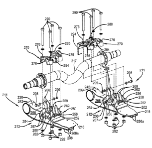
FIG. 1 is a top rear driver-side perspective view of an axle/suspension system
including a
pair of suspension assemblies connected to the axle by prior art axle-to-beam
connections;
FIG. 2 is a top rear driver-side perspective view of the heavy-duty vehicle
axle/suspension
system shown in FIG. 1, showing the component parts of the driver-side
suspension assembly,
including the prior art axle-to-beam connection, in exploded view;
FIG. 2A is an enlarged fragmentary perspective view of a portion of the driver-
side
suspension assembly shown in FIG. 1;
FIG. 3 is a top rear driver-side perspective view of an axle/suspension system
with a pair of
suspension assemblies connected to the axle by exemplary embodiment axle-to-
beam connections
of the disclosed subject matter;
FIG. 4 is a top rear driver-side perspective view of the axle/suspension
system shown in
FIG. 3, showing the component parts of the suspension assemblies, including
the exemplary
embodiment axle-to-beam connection of the disclosed subject matter, in
exploded view;
FIG. 5 is a driver-side elevational view of the axle/suspension system shown
in FIGS. 3-4,
showing the exemplary embodiment axle-to-beam connection of the disclosed
subject matter;
FIG. 6 is an enlarged fragmentary perspective view of a portion of the driver-
side suspension
assembly of the axle/suspension system shown in FIGS. 3-5, showing the
exemplary embodiment
axle-to-beam connection of the disclosed subject matter;
7
CA 03106300 2021-01-06
WO 2020/047028
PCT/US2019/048459
FIG. 7 is an enlarged fragmentary top plan view of a portion of the driver-
side suspension
assembly shown in FIG. 3, showing the exemplary embodiment axle-to-beam
connection of the
disclosed subject matter;
FIG. 8 is an enlarged rear fragmentary elevational view of the driver-side
suspension
assembly shown in FIGS. 3-7, showing the exemplary embodiment axle-to-beam
connection of the
disclosed subject matter;
FIG. 9 is a top rear perspective view of selected components of the driver-
side suspension
assembly of the axle/suspension system shown in FIGS. 3-8, showing components
of the alignment
assembly of the exemplary embodiment axle-to-beam connection of the disclosed
subject matter;
FIG. 10 is a top plan view of selected components of the driver-side
suspension assembly
including the alignment assembly of the exemplary embodiment axle-to-beam
connection shown in
FIG. 8;
FIG. 11 is an enlarged top rear driver-side perspective view of the top pad of
the exemplary
embodiment axle-to-beam connection of the disclosed subject matter shown in
FIGS. 3-7;
FIG. 12 is a top front perspective view of the top pad shown in FIGS. 10-11;
and
FIG. 13 is a top plan view of the top pad shown in FIGS. 10-12.
Similar reference characters indicate similar parts throughout.
DESCRIPTION OF THE PREFERRED EMBODIMENT
In order to better understand the environment in which the axle to beam
connection of the
disclosed subject matter is utilized, a liftable axle/suspension system 10
incorporating a pair of prior
art axle-to-beam connections 14 is shown in FIGS. 1-2A. Axle/suspension system
10 includes a
pair of transversely spaced mirror-image suspension assemblies 11. Because
suspension assemblies
8
CA 03106300 2021-01-06
WO 2020/047028
PCT/US2019/048459
11 are mirror-images of each other, only one of the suspension assemblies will
be described in
detail.
Suspension assembly 11 includes a beam 12 having a generally rigid metal box-
like
structure comprising a pair of transversely spaced vertical sidewalls 66. A
bottom wall 38, a first
top plate 39, and a second top plate 36 extend between and interconnect
sidewalls 66. Sidewalls 66
and bottom wall 38 are integrally formed as a single-piece with a generally U-
shaped cross-section
by stamping or bending. First top plate 39 and second top plate 36 are in a
longitudinal spaced
arrangement along beam 12 and secured to sidewalls 66 via welding or other
suitable means. Beam
12 also includes a mounting tube 42 formed of robust steel attached to the
front ends of sidewalls
66, bottom wall 38, and first top plate 39.
Beam 12 also includes a platform 16, which extends from the rear end of the
beam and is
rigidly attached by suitable means, such as welds, to sidewalls 66 adjacent
second top plate 36 near
the rear end of the beam. A conventional bellows-type air spring 9 is attached
to and extends
between platform 16 and a respective main member of the heavy-duty vehicle, as
is known. In
particular, air spring 9 has a mounting bracket 13 secured to the air spring
by nuts 83. Mounting
bracket 13 is secured to the main member with fasteners, as is known. Air
spring 9 is secured to
platform 16 with bolts 55 and washers 35. A shock absorber (not shown) may
also be attached to
and extend between beam 12 and the respective main member or hanger, as is
known. An axle 17
extends between and is rigidly connected to the rear end of each beam 12 by
components of prior art
axle-to-beam connection 14, as described in greater detail below. For purposes
of completeness,
axle/suspension system 10 is also shown having a respective wheel end assembly
29 with a drum
brake assembly 30 attached to each end of axle 17.
Beam 12 is pivotally mounted by a bushing assembly 40 to a hanger 18, which
depends from
and is secured to a main member (not shown) of a heavy-duty vehicle (not
shown), as is known.
9
CA 03106300 2021-01-06
WO 2020/047028
PCT/US2019/048459
Hanger 18 typically includes a generally box-like sturdy metal structure
having a pair of
transversely-spaced vertical sidewalls 22 extending between a vertical front
wall 21 and a vertical
rear wall 25. A top wall 37 extends between and is attached to front wall 21
and rear wall 25.
Bushing assembly 40 includes an elastomeric bushing 44 press fit into mounting
tube 42 of beam
12. Bushing 44 is molded about and adhesively attached to a central metal
sleeve 46 formed with
an opening 31, which extends through the sleeve. Sleeve 46 extends completely
through bushing 44
and protrudes outwardly from the bushing to facilitate pivotal mounting of
beam 12 on hanger 18.
Bushing assembly 40 includes a fastener assembly 15 having a bolt 20, which,
together with a nut
26, is utilized to secure the components of the bushing assembly together and
pivotally mount beam
12 to hanger 18. In particular, bolt 20 passes through a first washer 32, an
eccentric washer 19
disposed adjacent the outboard sidewall 22 of hanger 18, an opening 47 formed
in the outboard
sidewall of the hanger, opening 31 of bushing sleeve 46, an opening (not
shown) formed in the
inboard sidewall of the hanger, an inboard non-eccentric washer 24 disposed
adjacent the inboard
sidewall of the hanger, and a second washer 33 to receive nut 26. Eccentric
washer 19 provides a
means for adjusting alignment of axle/suspension system 10, as is known. In
addition, a respective
one of a pair of conventional spacer discs 34, formed of ultra-high molecular
weight polyethylene,
is disposed between bushing 44 and each sidewall 22 of hanger 18 to prevent
contact between metal
components of mounting tube 42 and the hanger.
Suspension assembly 11 also includes a lift assembly 80, which enables beam 12
with axle
17 to be lifted and maintained in a raised position by prior art axle-to-beam
connection 14 during
certain heavy-duty vehicle operations. Lift assembly 80 generally includes an
elastorneric bellows-
type air chamber 82 and a lift arm 84. Lift arm 84 is rigidly attached, such
as by welding, to
mounting tube 42 of beam 12 and extends upwardly into hanger 18. The front end
of air chamber
82 is attached to the rear surface of lift arm 84 by fasteners 85. The rear
end of air chamber 82 is
CA 03106300 2021-01-06
WO 2020/047028
PCT/US2019/048459
attached to the front surface of rear wall 25 of hanger 18 by fasteners 87. As
air from an air supply
source (not shown) installed on the heavy-duty vehicle is introduced into air
chamber 82, and as air
is simultaneously released from air spring 9, the air chamber expands away
from rear wall 25 of
hanger 18 and applies a forward force on lift arm 84. This forward force
causes arcuate upward
movement of beam 12 about bushing assembly 40 that enables suspension assembly
11, axle 17,
and wheel end assetnbly 29 attached to the axle to be lifted and maintained in
a raised position.
As described above, axle 17 is connected to suspension assembly 11 utilizing
prior art axle-
to-beam connection 14. Prior art axle-to-beam connection 14 generally includes
a front U-bolt
bracket/axle seat 28F and a rear U-bolt bracket/axle seat 28R connected to or
integrated into beam
12. With particular reference to FIGS. 2-2A, both front and rear U-bolt
brackets/axle seats 28F,
28R include a generally vertical interconnecting member 41, a generally
horizontal member 61, and
a strengthening web 65. Interconnecting member 41 includes a lower portion 45,
an upper portion
53 with a terminal edge 59, and a surface 62. Each horizontal member 61
includes a pair of
openings 72, each of which is formed through the inboard and outboard side of
the respective
horizontal member. Lower portion 45 of front U-bolt bracket/axle seat 28F
nests in a pair of
transversely-spaced front slots 70F formed in sidewalls 66 of beam 12 adjacent
the rear end of first
top plate 39. Lower portion 45 of U-bolt bracket/axle seat 28F extends
downwardly adjacent to the
front portion of axle 17, such that surface 62 faces the front portion of the
axle, and is rigidly
secured to beam 12 using any suitable method, such as welding. Similarly,
lower portion 45 of rear
U-bolt bracket/axle seat 28R nests in a pair of transversely-spaced rear slots
70R formed in
sidewalls 66 of beam 12 spaced a longitudinal distance from front slots 70F
and adjacent the front
end of second top plate 36. Lower portion 45 of U-bolt bracket/axle seat 28R
extends downwardly
toward and adjacent to the rear portion of axle 17, such that surface 62 faces
the rear portion of the
axle, and is rigidly secured to beam 12 using any suitable method, such as
welding. The upper
11
CA 03106300 2021-01-06
WO 2020/047028
PCT/US2019/048459
edges of sidewalls 66 of beam 12 are each integrally formed with an arch 50
between front and rear
slots 70F, 70R. U-bolt bracket/axle seats 28F, R, together with arches 50,
form an axle locus 51,
which is generally known or referred to as an axle seat.
Prior art axle-to-beam connection 14 requires a pair of generally identical
inboard and
outboard connections for attaching axle 17 to beam 12 of the respective
suspension assembly 11.
This is typically accomplished by a pair of U-bolts 27. Each U-bolt 27 is
disposed about axle 17
and through openings 72 of front and rear U-bolt brackets/axle seats 28F, 28R,
respectively. A
washer 52 (FIG. 2) is disposed over each of a respective one of a pair of
threaded ends of U-bolt 27.
A nut 73 threadably engages each of a respective one of the pair of ends of U-
bolt 27 and is
tightened to secure axle 17 into axle locus 51 of beam 12.
In addition, axle 17 is also irremovably attached to front and rear U-bolt
bracket/axle seats
28F, 28R by a front line weld (not shown) and a rear line weld 90R (FIG. 1).
The front line weld is
formed along the interface between terminal edge 59 of upper portion 53 of
interconnecting member
41 of front U-bolt bracket/axle seat 28F and axle 17 at or just beyond the
horizontal centerline of the
axle. Similarly, rear line weld 90R is formed along the interface between
terminal edge 59 of upper
portion 53 of interconnecting member 41 of rear U-bolt bracket/axle seat 28R
and axle 17 at or just
beyond the horizontal centerline of the axle. Together, U-bolts 27, the front
line weld, and rear line
weld 90R rigidly attach axle 17 to beam 12 of suspension assembly 11 to
complete prior art axle-to-
beam connection 14.
Prior art axle-to-beam connection 14, while adequately securing axle 17 to
beam 12 of
suspension assembly 11, has disadvantages, drawbacks, and limitations. For
example, during
heavy-duty vehicle operation under harsh driving conditions, such as on harsh
road surfaces, prior
art axle-to-beam connection 14 potentially has reduced fatigue strength and
durability. In particular,
the starting and the termination points of the front line weld and rear line
weld 90R on axle 17
12
CA 03106300 2021-01-06
WO 2020/047028
PCT/US2019/048459
create stress risers on or near axle-to-beam connection 14. These stress
risers can potentially
compromise axle-to-beam connection 14 and axle 17 during heavy-duty vehicle
operation under
harsh driving conditions, due to forces imposed on the axle-to-beam
connection, and cause failure
of the line welds. More particularly, during heavy-duty vehicle operation
certain forces are
imparted from beam 12 substantially through the front line weld and rear line
weld 90R to axle 17,
which can potentially result in failure of axle-to-beam connection 14, thereby
increasing heavy-duty
vehicle downtime and repair cost.
In addition, because axle 17 is irremovably connected to beam 12 of suspension
assembly 11
during manufacturing, axle/suspension system 10 must be shipped with the axle
attached to the
beams of the suspension assemblies, increasing the cost of and amount of space
required for
shipments as compared to separately shipping the axles and the suspension
assemblies. Moreover,
suspension assemblies 11 require bump stops, or other discrete components to
protect contact
between and potential damage to prior art axle-to-beam connections 14 and the
members of the
heavy-duty vehicle during jounce events, undesirably increasing the weight,
manufacturing cost,
and complexity of axle/suspension system 10. The axle-to-beam connection of
the disclosed subject
matter overcomes the disadvantages, drawbacks, and limitations associated with
prior art axle-to-
beam connection 14 and provides additional benefits.
An exemplary embodiment axle-to-beam connection 200 of the disclosed subject
matter is
shown in FIGS. 3-13 utilized in conjunction with a beam 212 and an axle 217 of
an axle/suspension
system 210.
Axle/suspension system 210 is similar in construction and arrangement to
axle/suspension
system 10 (FIGS. 1-2A) described above. Axle/suspension system 210 includes a
pair of
transversely-spaced mirror-image suspension assemblies 211 depending from
respective main
members (not shown) of a heavy-duty vehicle (not shown). Axle 217 extends
transversely between
13
CA 03106300 2021-01-06
WO 2020/047028
PCT/US2019/048459
and is rigidly connected to each suspension assembly 211 by exemplary
embodiment axle-to-beam
connection 200. Because suspension assemblies 211 are mirror images of each
other and for
purposes of conciseness and clarity, only one of the suspension assemblies
will be described in
detail.
Suspension assembly 211 includes beam 212, which is a generally rigid metal
box-like
structure. With particular reference to FIGS. 9-10, beam 212 generally
comprises a pair of
transversely spaced vertical sidewalls 266 interconnected by a longitudinal
top plate 239 and a
longitudinal bottom plate 238. Bottom plate 238 is rigidly attached by any
method, such as
welding, to sidewalls 266 and extends slightly inboardly and outboardly of the
sidewalls. A
mounting tube 242 (FIG. 9) formed of any suitably robust material, such as
steel, is rigidly attached
to the front ends of sidewalls 266, top plate 239, and bottom plate 238. Beam
212 is pivotally
attached by a bushing assembly 240 to a hanger 218, which depends from and is
secured to the main
member of the heavy-duty vehicle by any suitable means, such as welds or
fasteners. Bushing
assembly 240 is similar in structure and function to bushing assembly 40
(FIGS. 1-2A) described
above and is disposed in mounting tube 242. Hanger 218 includes a generally
box like sturdy metal
structure having a pair of transversely-spaced vertical sidewalls 222 attached
to and extending
between a vertical front wall 221 and a vertical rear wall 225.
Beam 212 also includes a front support plate 254 and a rear support plate 256
to
accommodate mounting and/or attachment of components of exemplary embodiment
axle-to-beam
connection 200 to beam 212, as will be described in greater detail below. Rear
support plate 256 is
disposed transversely across beam 212 near the rear end of top plate 239 and
extends downwardly
into the beam. In particular, the rear of each sidewall 266 of beam 212
contacts the front surface of
rear support plate 256, which is suitably attached, such as by welding, to the
sidewalls. An inboard
and outboard portion of rear support plate 256 also extend laterally outward
of and downwardly
14
CA 03106300 2021-01-06
WO 2020/047028
PCT/US2019/048459
adjacent to the respective inboard and outboard surfaces of sidewalls 266 and
contact or abut bottom
plate 238 of beam 212. Rear support plate 256 is also rigidly attached, such
as by welding, to the
respective inboard and outboard surfaces of sidewalls 266. With particular
reference to FIG. 8, rear
support plate 256 is also formed with a pair of notches 257 through which top
plate 239 of beam
212 extends to further integrate the rear support plate with the beam.
With particular reference to FIGS. 9-10, front support plate 254 is spaced a
longitudinal
distance forward of rear support plate 256 along beam 212. Front support plate
254 is positioned on
a respective inboard or outboard surface of sidewall 266 of beam 212, extends
downwardly over the
respective inboard or outboard surface of the sidewall, and contacts bottom
plate 238 of the beam.
Front support plate 254 is rigidly attached, such as by welding, to the
respective outboard or inboard
surface of sidewall 266. Front support plate 254 has a transverse profile,
which corresponds and is
longitudinally-aligned with a respective inboard or outboard portion of rear
support plate 256.
Beam 212 includes a platform 216, which is rigidly attached by welding or
other suitable
means to a pair of rearwardly extending beam extensions 266a integrally formed
with sidewalk; 266
near the rear end of beam 212. Beam 212 also includes at least one, but, more
preferably, a pair of
gussets 223 (FIG. 8; only one shown), which provide support to platfolui 216.
In particular, gussets
223 are attached between the bottom surface of platform 216 and the top
surface of bottom plate
238. More specifically, gussets 223 extend inboardly from the inboard surface
of the outboard
beam extension 266a through a slot (not shown) formed in the inboard beam
extension 266a to a
.. location adjacent the inboard edge of platform 216. The front end of
platform 216 contacts the rear
surface of rear support plate 256 and is rigidly attached, such as by welding,
to the rear support
plate. Platform 216 extends from the rear end of beam 212 and supports a
conventional bellows-
type air spring (not shown) that is attached to and extends between the
platform and a respective
main member of the heavy-duty vehicle, as is known.
CA 03106300 2021-01-06
WO 2020/047028
PCT/US2019/048459
Beam 212 is connected to a lift assembly 214 (FIGS. 9-10; partially shown)
that is similar in
structure and function to lift assembly 80 (FIGS. 1-2), described above. Lift
assembly 214 enables
beams 212 and axle 217, attached to the beams in a manner described below, to
be lifted and
maintained in a raised position during certain heavy-duty vehicle operations.
Lift assembly 214
generally includes an elastomeric bellows-type air chamber (not shown) and a
lift arm 215. Lift arm
215 is rigidly attached, such as by welding, to mounting tube 242 of beam 212
and extends
upwardly into hanger 218. The front end of the air chamber is attached to the
rear surface of lift
arm 215 by fasteners (not shown). The rear end of the air chamber is attached
to the front surface of
rear wall 225 of hanger 218 by fasteners (not shown). As air from an air
supply source (not shown)
installed on the heavy-duty vehicle is introduced into the air chamber, and
air is simultaneously
released from the air spring, the air chamber expands away from rear wall 225
of hanger 218,
applying force to lift arm 215 and causing arcuate upward movement of beam 212
about bushing
assembly 240, thereby enabling axle/suspension system 210, axle 217, and
wheels (not shown)
attached to the axle to be lifted and maintained in a raised position.
In accordance with an important aspect of the disclosed subject matter,
exemplary
embodiment axle-to-beam connection 200 of axle/suspension system 210 also
includes alignment
structures, enabling beam 212 to be accurately aligned with axle-to-beam
connection 200 and
quickly attached to axle 217. In particular, axle-to-beam connection 200
comprises a two-part
connection, which generally includes an axle alignment assembly 250 and a top
pad 270. More
particularly, and with particular reference to FIGS. 9-10, alignment assembly
250 is rigidly
connected or integrated into beam 212 of suspension assembly 211. Alignment
assembly 250
includes a bottom plate 252 positioned on the top surface of top plate 239 of
beam 212. Alignment
assembly 250 includes a pair of longitudinally-extending vertically-oriented
outer seating plates 262
rigidly attached, such as by welding, to a respective inboard and outboard
side of bottom plate 252.
16
CA 03106300 2021-01-06
WO 2020/047028
PCT/US2019/048459
One of the pair of outer seating plates 262 is positioned between the outboard
surface of the
outboard sidewall 266 of beam 212 and both an inboard facing surface of the
outboard front support
plate 254 and an inboard facing surface of the outboard portion of rear
support plate 256 and is
rigidly attached, such as by welding, to the front support plate and the rear
support plate. Likewise,
the other one of the pair of outer seating plates 262 is positioned between
the inboard facing surface
of the inboard sidewall 266 of beam 212 and both the outboard facing surface
of the inboard front
support plate 254 and the outboard facing surface of the inboard portion of
rear support plate 256
and is rigidly attached, such as by welding, to the front support plate and
the rear support plate. .
Alignment assembly 250 also includes a pair of bolt brackets 260. Each bolt
bracket 260
extends transversely outward from the respective outer seating plate 262 of
alignment assembly 250
and longitudinally between each respective inboard or outboard portion of
front support plate 254
and the corresponding portion of rear support plate 256. Each bolt bracket 260
is rigidly attached,
such as by welding, to the respective front support plate 254, outer seating
plate 262, and rear
support plate 256 to further rigidly attach alignment assembly 250 to beam
212. With particular
reference to FIGS. 4, 6, and 9-10, a pair of longitudinally-spaced,
transversely-extending gussets
267 are rigidly attached, such as by welding, between each bolt bracket 260
and its respective outer
seating plate 262 to reinforce the bolt bracket. Each bolt bracket 260 is
formed with a pair of
longitudinally spaced and transversely-aligned openings 261 for receiving a
respective number of
bolts 290, as described below.
With continued reference to FIGS. 9-10, alignment assembly 250 further
includes a front
lateral support plate 251 and a rear lateral support plate 253. Front and rear
lateral support plates
251, 253 are disposed on or adjacent the front and rear of bottom plate 252,
respectively, extend
transversely between outer seating plates 262, and are rigidly attached to the
outer seating plates and
the bottom plate by any suitable means, such as welds. A pair of
longitudinally-extending
17
CA 03106300 2021-01-06
WO 2020/047028
PCT/US2019/048459
vertically-oriented inner seating plates 264 are each formed with a pair of
longitudinally-aligned
notches (not shown) which align with and are disposed over front and rear
lateral support plates
251, 253. Inner seating plates 264 are seated on bottom plate 252 and
transversely-spaced between
outer seating plates 262. Inner seating plates 264 are rigidly attached, such
as by welding, to bottom
plate 252, front lateral support plate 251, and rear lateral support plate
253. Each one of inner and
outer seating plates 264, 262, respectively, is formed with a respective
arcuate or other suitably-
shaped edge 265, 263. Edges 263, 265 are transversely aligned to create an
axle seat or axle locus
258. Each of inner seating plates 264 may also be formed with a respective one
of a pair of
transversely aligned openings 296. Openings 296 enable a shock absorber (not
shown) to be
.. mounted and secured to alignment assembly 250 by a fastener or a bolt 298
and a nut 299 (FIGS. 4-
8).
With particular reference to FIGS. 11-13, top pad 270 of axle-to-beam
connection 200
includes a body 272 with a generally inverted U-shaped cross-section. Body 272
is formed as a
single piece by any suitable process, such as casting or forging, from any
suitable material, such as
steel or ductile iron, to provide the body with a sturdy, resilient structure.
Body 272 is formed with
a generally arcuate curvature 281 at an outboard end of the body. Curvature
281 may have any
suitable dimension or shape, such that the curvature is complementary to and
disposed on and
partially about a portion of axle 217, partially encompassing the axle (FIG.
6).
With particular reference to FIGS. 6-8, 11, and 13, body 272 of top pad 270
includes a pair
of transversely-spaced rear notches 279, which form a rear alignment flange
284 therebetween.
Similarly, body 272 also includes a pair of transversely spaced front notches
277 (FIGS. 7 and 11-
13), which foul" a front alignment flange 282, which is longitudinally aligned
with rear alignment
flange 284. Body 272 is formed with two pairs of longitudinally parallel
openings 276. Each pair
of openings 276 is formed in body 272 near a respective inboard or outboard
end of the body. Rear
18
CA 03106300 2021-01-06
WO 2020/047028
PCT/US2019/048459
alignment flange 284 nests between a pair of rear alignment portions 269, each
integrally formed
with respective inner seating plates 264, such that openings 276 of top pad
270 are vertically aligned
with the respective openings 261 of the respective bolt bracket 260 of
alignment assembly 250
(FIG. 6). Similarly, front alignment flange 282 nests between a pair of front
alignment portions
268, each integrally formed with inner seating plates 264, such that openings
276 of top pad 270 are
vertically aligned with the respective openings 261 of the respective bolt
bracket 260. In this
manner, axle-to-beam connection 200 enables quick and accurate alignment of
axle 217, top pad
270, and alignment assembly 250 of beam 212.
In accordance with another important aspect of the disclosed subject matter,
exemplary
embodiment axle-to-beam connection 200 provides a strong and secure connection
between axle
217 and beam 212, while eliminating line welds on the axle. In particular, a
window 274 is formed
through body 272 of top pad 270 on or adjacent to the longitudinal and
transverse centers of the
body. More particularly, a continuous weld CW (FIGS. 6-7) is laid along the
inside of window 274
between the continuous inner perimeter of the window and the top of axle 217
to rigidly secure top
pad 270 to the axle. Continuous weld CW minimizes or eliminates the formation
of stress risers,
providing a generally stronger and more resilient connection compared to line
welds of the prior art.
In addition, body 272 also extends transversely along and partially
encompasses axle 217 both
inboardly and outboardly from continuous weld CW at window 274, allowing top
pad 270 to react
forces imparted on axle-to-beam connection 200 during operation of the heavy-
duty vehicle, thereby
reducing stress on the continuous weld and further strengthening the axle-to-
beam connection.
Furthermore, because both front and rear support plates 254, 256 are attached
to or integrated into
beam 212, loads imparted on axle-to-beam connection 200 are transferred
throughout the structure
of the beam, providing additional torsional stiffness to, and reducing stress
on, the axle-to-beam
connection. Thus, by utilizing continuous weld CW to attach top pad 270 to
axle 217 in
19
CA 03106300 2021-01-06
WO 2020/047028
PCT/US2019/048459
combination with the structure of the top pad, exemplary embodiment axle-to-
beam connection 200
provides a stronger, more resilient and secure connection capable of
withstanding forces imparted
on the axle-to-beam connection during operation of the heavy-duty vehicle in
harsh driving
conditions, such as on harsh road surfaces.
In accordance with yet another important aspect of the disclosed subject
matter, exemplary
embodiment axle-to-beam connection 200 enables removable attachment of axle
217 to beam 212.
More specifically, bolts 290 (FIGS. 3-8) are disposed through openings 276 of
top pad 270 and the
respective vertically aligned openings 261 of alignment assembly 250 to
removably secure the top
pad to the alignment assembly once corresponding nuts 292 (FIGS. 3-5) are
tightened, thereby
securing axle 217 to beam 212 of suspension assembly 211 to complete exemplary
embodiment
axle-to-beam connection 200. Because top pad 270 is rigidly attached to axle
217 by continuous
weld CW and can be securely and removably connected to alignment assembly 250
of beam 212
utilizing bolts 290 and nuts 292, the axle does not need to be welded to the
beam and/or components
of the beam alignment assembly. As a result, axle 217 with top pad 270
attached and suspension
assemblies 211 can be shipped separately and assembled on site without welding
equipment,
decreasing shipping costs as compared to axle/suspension systems utilizing
prior art axle-to-beam
connections with axles irremovably attached to the suspension assemblies
during manufacturing.
Body 272 is also formed with a brake chamber mounting structure 294 (FIGS. 11-
13) that is
adjacent the inboard end of and extends frontwardly and downwardly from the
body. Brake
chamber mounting structure 294 is formed with a pair of longitudinal threaded
openings 295
arranged vertically in parallel, enabling attachment of a brake chamber
bracket (not shown) that
supports a brake air chamber (not shown).
In accordance with yet another important aspect of the disclosed subject
matter, body 272 of
top pad 270 is formed with a substantially vertically extending boss 280. Boss
280 is formed, such
CA 03106300 2021-01-06
WO 2020/047028
PCT/US2019/048459
that it is substantially aligned with the respective main member of the heavy-
duty vehicle to which
the respective hanger 218 is attached. Boss 280 acts as a bump stop capable of
sufficiently reacting
forces imparted on top pad 270, and thus axle-to-beam connection 200, during
extreme jounce
events of suspension assembly 211 when the top pad strikes the respective main
member of the
heavy-duty vehicle. Thus, boss 280 prevents potential damage to components of
axle-to-beam
connection 200 and axle 217 during extreme jounce events, while eliminating
the need for discrete
bump stops attached to or incorporated into components of axle/suspension
system 210 and/or the
main member of the heavy-duty vehicle, and reducing heavy-duty vehicle
manufacturing costs and
complexity.
Thus, exemplary embodiment axle-to-beam connection 200 of the disclosed
subject matter is
relatively lighter, reduces manufacturing cost and complexity, eliminates line
welds on axle 217,
includes structure that minimizes stress on the axle, and facilitates
removable attachment of axle to
beam 212, thereby providing a stronger, more resilient axle-to-beam connection
and enabling
separate shipment of the axle and suspension assemblies 211 and on-site
assembly without the need
for welding equipment. Exemplary embodiment axle-to-beam connection 200 of the
disclosed
subject matter also provides alignment assembly 250 incorporated into beam
212, which enables top
pad 270 and axle 217 to be accurately aligned with the beam to facilitate
quick and simplified
attachment, thereby increasing assembly efficiency and reducing labor costs.
In addition,
exemplary embodiment axle-to-beam connection 200 provides top pad 270 with
boss 280 to act as a
mechanical bump stop to prevent damage to components of axle/suspension system
210 during
jounce events.
It is understood that axle-to-beam connection 200 of the disclosed subject
matter can include
additional or alternative means for securing the connection between axle 217
and beam 212 without
affecting the overall concept or operation of the disclosed subject matter. It
is contemplated that
21
CA 03106300 2021-01-06
WO 2020/047028
PCT/US2019/048459
alignment assembly 250 and top pad 270 of axle-to-beam connection 200 could
have different
structures than those shown, such as having different foinis and/or including
different components,
without affecting the overall concept or operation of the disclosed subject
matter.
It is contemplated that exemplary embodiment axle-to-beam connection 200 of
the disclosed
subject matter could be utilized on heavy-duty vehicles having frames or
subframes, which are
moveable or non-movable, and having one or more than one axle without changing
the overall
concept or operation of the disclosed subject matter. It is also contemplated
that axle-to-beam
connection 200 of the disclosed subject matter could be utilized in
conjunction with leading- and/or
trailing-arm beam-type axle/suspension system designs with bottom-
mount/unclerslung, top-
mount/overslung, or top-mount/underslung beams, including beams made of any
suitable material,
such as metal, metal alloy, composite, and/or combinations thereof, or with
different designs and/or
configurations than those shown and described, such as solid beams, shell-type
beams, truss
structures, intersecting plates, spring beams and parallel plates, without
changing the overall
concept or operation of the disclosed subject matter. It is yet even further
contemplated that axle-to-
beam connection 200 of the disclosed subject matter could be utilized in
conjunction with axles
having any suitable structure, such as straight axles or raised-center axles,
and any suitable fixed or
varied wall thicknesses or other cross-sectional or overall shapes without
changing the overall
concept or operation of the disclosed subject matter. The disclosed subject
matter also finds
application in intermediary structures such as spring seats.
Accordingly, the axle-to-beam connection of the disclosed subject matter is
simplified;
provides an effective, safe, inexpensive and efficient structure and method,
which achieve all the
enumerated objectives; provide for eliminating difficulties encountered with
prior art axle-to-beam
connections; and solve problems and obtain new results in the art.
22
CA 03106300 2021-01-06
WO 2020/047028
PCT/US2019/048459
In the foregoing description, certain terms have been used for brevity,
clarity, and
understanding, but no unnecessary limitations are to be implied therefrom
beyond the requirements
of the prior art because such terms are used for descriptive purposes and are
intended to be broadly
construed.
The subject disclosure has been described with reference to a specific
embodiment. It is
understood that this description and illustration is by way of example and not
by way of limitation.
Potential modifications and alterations will occur to others upon a reading
and understanding of this
disclosure, and it is understood that the subject disclosure includes all such
modifications,
alterations, and equivalents thereof.
Having now described the features, discoveries and principles of the disclosed
subject
matter; the manner in which the axle-to-beam connection is used and installed;
the characteristics of
the construction, arrangement, and method steps; and the advantageous, new,
and useful results
obtained, the new and useful structures, devices, elements, arrangements,
process, parts, and
combinations are set forth in the appended claims.
23