Note: Descriptions are shown in the official language in which they were submitted.
CA 03106330 2021-01-12
WO 2020/010470
PCT/CA2019/050968
1
SCHOOL BUS STOP ARM AND DRIVE UNIT THEREFOR
FIELD
The present disclosure relates generally to stop arms for school buses,
and more particularly to stop arms with illuminated signs and drive control
units for
moving stop arms between their deployed and retracted positions on the side of
a
school bus.
BACKGROUND
School bus stop arms are deployed to indicate to other motorists the
need to stop while the school bus loads and unloads passengers. In many
jurisdictions, such stop arms are a legal requirement. The stop arms are
typically
mounted on a driver's side of the school bus and deployed from a retracted
position
near the school bus wall to a deployed position extending from the wall. Power
from
the electrical system of the vehicle may be used to supply power to the stop
arm. In
some cases, stop arms may be operated using compressed air.
SUMMARY
In some embodiments according to the present disclosure, there is provided a
stop
arm for a school bus comprising: a stop sign; and a drive unit mountable to a
side of
the school bus for selectively moving the stop sign between a deployed
position and
a retracted position, said drive unit comprising: a motor operably coupled to
the stop
CA 03106330 2021-01-12
WO 2020/010470
PCT/CA2019/050968
2
sign to perform said selective movement, one or more position sensors operable
to
detect the presence of the stop sign in the deployed and retracted positions,
and
a controller operably coupled to the motor for controlling operation of the
motor, the
controller configured to, during operation of the motor, (i) monitor one or
more
operating characteristics of the motor for conditions indicative of an
obstruction to
movement of the stop sign, (ii) monitor the position sensor for a confirmation
signal
indicative of the presence of the stop sign in the deployed or retracted
position, and
(iii), based on the conditions indicative of an obstruction and the
confirmation signal,
determine if the stop sign has reached one of the deployed and retracted
positions or
is being obstructed.
In some embodiments of the present disclosure, there is provided a
stop arm for a school bus comprising: a stop sign; and a drive unit mountable
to a
side of the school bus for selectively moving the stop sign between a deployed
position and a retracted position, said drive unit comprising: a motor
operably coupled
to the stop sign to perform said selective movement, a controller operably
coupled to
the motor for controlling operation of the motor, and a housing defining an
interior
space of said housing and an enclosed sub-compartment divided from a remainder
of
the interior space, the motor being positioned within the sub-compartment,
wherein at
least one of: (a) a position sensor operable to detect the presence of the
stop sign in
one or more positions is contained within said sub-compartment; (b) a PCB, on
which
the controller and/or the position sensor are mounted, is contained within
said sub-
compartment; and (c) a motor-driven output shaft extends from the sub-
compartment
in a downward direction through a lower wall of said sub-compartment.
CA 03106330 2021-01-12
WO 2020/010470
PCT/CA2019/050968
3
In some embodiments of the present disclosure, there is provided a
stop arm for a school bus comprising: a stop sign with at least one light
incorporated
thereon; and a drive unit mountable to a side of the school bus for
selectively moving
the stop sign between a deployed position and a retracted position, said drive
unit
having a housing containing: a motor operably coupled to the stop sign to
perform
said selective movement, a controller operably coupled to the motor for
controlling
operation of the motor and operably coupled to the at least one light for
selectively
controlling illumination of the at least one light in a flashing mode or a
strobing mode,
wherein selection of the flashing mode or the strobing mode is made by closure
of a
circuit accessible from an exterior of the housing when the housing is
assembled.
In some embodiments of the present disclosure, there is provided a stop arm
for a
school bus comprising: a stop sign; and a drive unit mountable to a side of
the school
bus for selectively moving the stop sign between a deployed position and a
retracted
position, said drive unit comprising a motor operably coupled to the stop sign
to
perform said selective movement, and a loading device coupled to the motor and
configured to physically load the motor and increase the force needed to be
overcome to move the sign when the drive unit is in an unpowered state.
In some embodiments of the present disclosure, there is provided a
stop arm for a school bus comprising: a stop sign; and a drive unit mountable
to a
side of the school bus for selectively moving the stop sign between a deployed
position and a retracted position, said drive unit comprising: a controller
for controlling
operation of the stop arm, and an energy storage device operably coupled to
the
controller, the controller configured to direct energy from the energy storage
device
for use in operation of the stop arm.
CA 03106330 2021-01-12
WO 2020/010470
PCT/CA2019/050968
4
In some embodiments of the present disclosure, there is provided a stop arm
for a
school bus comprising: a stop sign with one or more illumination elements; and
a drive unit mountable to a side of the school bus for selectively moving the
stop sign
between a deployed position and a retracted position, said drive unit
comprising:
a motor operably coupled to the stop sign to perform said selective movement,
and
a controller operably coupled to the motor and the stop sign for controlling
operation
of the motor and for controlling illumination of the one or more illumination
elements,
wherein the controller is configured to reduce a brightness of the one or more
illumination elements during operation of the motor to move the sign between
the
deployed and retracted positions.
In some embodiments of the present disclosure, there is provided a
stop arm for a school bus comprising: a stop sign; and a drive unit mountable
to a
side of the school bus for selectively moving the stop sign between a deployed
position and a retracted position, said drive unit comprising a controller for
controlling
operation of the stop arm, wherein the controller is configured to monitor a
voltage of
a signal from the school bus and periodically load the signal if the voltage
is within a
predetermined range in order to determine if the signal is an intended control
signal.
In some embodiments of the present disclosure, there is provided a
stop arm for a school bus comprising: a stop sign; and a drive unit mountable
to a
side of the school bus for selectively moving the stop sign between a deployed
position and a retracted position, said drive unit comprising: a motor
operably coupled
to the stop sign to perform said selective movement, and a controller operably
coupled to the motor for controlling operation of the motor, wherein the
controller is
configured to detect a nominal voltage of an electrical system of the school
bus and,
CA 03106330 2021-01-12
WO 2020/010470
PCT/CA2019/050968
based on the detected nominal voltage, adjust a threshold voltage of a control
signal
required to initiate deployment of the stop sign.
In some embodiments of the present disclosure, there is provided a
stop arm for a school bus comprising: a stop sign; and a drive unit mountable
to a
5 side of the school bus for selectively moving the stop sign between a
deployed
position and a retracted position, said drive unit comprising: a motor
operably coupled
to the stop sign to perform said selective movement, and a controller operably
coupled to the motor for controlling operation of the motor, wherein the
controller is
configured to monitor one or more parameters influencing a time required to
move
the stop sign between the deployed and retracted positions, and to adjust
control of
the motor based on the one or more monitored parameters so that the time
required
to move the stop sign between the deployed and retracted positions is within a
predetermined range.
In some embodiments of the present disclosure, there is provided a
stop arm for a school bus comprising: a stop sign comprising a sign assembly
including: at least one stop insignia, each stop insignia comprising a
respective
written stop message on a backdrop surrounding said respective written stop
message, and at least one internal illumination device installed within said
sign
assembly and configured to backlight both the respective written stop message
and
the respective backdrop upon activation of said internal illumination device;
and
a drive unit mountable to a side of the school bus for selectively moving the
stop sign
between a deployed position and a retracted position.
BRIEF DESCRIPTION OF THE DRAWINGS
CA 03106330 2021-01-12
WO 2020/010470
PCT/CA2019/050968
6
Embodiments of the present disclosure will now be described in
conjunction with the accompanying drawings in which:
Figure 1 is a top front perspective view of an illuminated, flasher-
equipped school bus stop arm according to a first embodiment of the present
disclosure.
Figure 2 is a top rear perspective view of the school bus stop arm of
Figure 1.
Figure 3 is a front elevation view of a stop lamp assembly from the
school bus stop arm of Figures 1 and 2.
Figure 4 is an exploded front perspective view of the stop lamp
assembly of Figure 3.
Figure 5 is an isolated perspective view of a frame of the school bus
stop arm of Figure 1.
Figure 6A is a perspective view of a first frame component of the frame
of Figure 5, illustrating snap fit placement of a first stop lamp assembly
therein during
assembly of the school bus stop arm.
Figure 6B is a perspective view of a second frame component of the
frame of Figure 5, illustrating snap fit placement of a second stop lamp
assembly
therein during assembly of the school bus stop arm.
Figure 6C is a partial closeup view of the frame component of Figure 6B
illustrating one of the snap tabs thereof for retaining the inserted stop lamp
assembly.
Figure 7 is a top front perspective view of an illuminated flasherless
school bus stop arm according to a second embodiment of the present
disclosure.
Figure 8 is a top rear perspective view of the school bus stop arm of
CA 03106330 2021-01-12
WO 2020/010470
PCT/CA2019/050968
7
Figure 7.
Figure 9 is a front view of a drive unit housing of the bus stop arm of
Figure 1 or Figure 7 with a front shell thereof removed to reveal internal
components
of the drive unit.
Figure 10 is a front view of the drive unit of Figure 9 with a compartment
cover thereof removed to reveal mounting of a motor assembly of the drive unit
within
an enclosed sub-compartment of the drive unit housing.
Figures 11A, 11B and 11C are cross-sectional views of the drive unit of
Figure 10 as viewed along line XI ¨ XI thereof, with an output shaft of the
motor
assembly in different rotational positions respectively corresponding to
retracted,
deployed and intermediate positions of the stop sign.
Figures 12A and 12B are top front and top rear perspective views,
respectively, of the deployed position of a non-illuminated school bus stop
arm
according to a third embodiment, which features the same drive unit as the
first and
second embodiments.
Figures 13A and 13B are top front and top rear perspective views,
respectively, of the retracted position of the third embodiment school bus
stop arm.
Figure 14 is an enlarged view of a position sensor according to another
embodiment of the present disclosure.
Figure 15 is a perspective view of a rear of a stop arm drive unit
according to one embodiment of the present disclosure.
Figure 16 is a perspective view of a motor assembly and loading device
according to one embodiment of the present disclosure.
Figure 17 is a schematic view of a control system including an energy
CA 03106330 2021-01-12
WO 2020/010470
PCT/CA2019/050968
8
storage device according to one embodiment of the present disclosure.
DETAILED DESCRIPTION
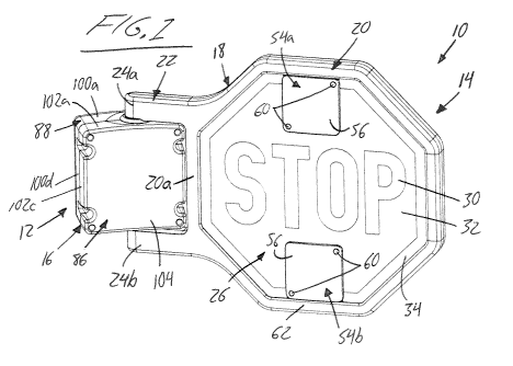
Figures 1 and 2 illustrate a first embodiment of the present disclosure,
.. in which a school bus stop arm 10 features a drive unit 12 on which an
illuminated
stop sign 14 is movably carried for pivotal motion relative thereto about a
vertically
upright pivot axis for movement between a deployed position and a retracted
position.
A housing 16 of the drive unit doubles as both a mount by which the stop arm
is
attachable to the exterior side wall of a school bus, and a protective
enclosure for
.. internal components of the drive unit. The drive unit 12 is operable to
selectively
pivot the illuminated stop sign 14 between the deployed and retracted
positions. The
stop sign of the installed stop arm lies generally parallel to the side wall
of the bus in
contact or close proximity thereto when in the retracted position, and reaches
laterally
outward from the side wall of the school bus in generally perpendicular
relation
.. thereto when in the deployed position. The vertical planes in which
retracted and
deployed positions of the illuminated stop sign are thus disposed at
approximately
90-degrees to one another.
The illuminated stop sign features a frame 18 having an octagonal sign
section 20 and a dual-armed support section 22 featuring a pair of parallel
support
.. arms 24a, 24b emanating outward from a vertical segment 20a of the
octagonal sign
section nearest to drive unit housing 16. The other seven segments of the sign
section 20 cooperate with this housing-adjacent vertical segment 20a to denote
the
overall octagonal shape of the sign section, and to delimit a hexagonal open
space
thereof in which one or more stop lamp assemblies are installed to provide the
stop
CA 03106330 2021-01-12
WO 2020/010470
PCT/CA2019/050968
9
sign with an illuminating functionality.
The illustrated embodiment is particularly useful as a front stop arm of a
school bus, and thus features a double-sided stop sign having a first stop
insignia 26
disposed within the octagonal space delimited by the sign section 20 of the
frame 18
and visible from a first or front side of the sign, and a matching second stop
insignia
28 likewise disposed within the octagonal space of the frame's sign section
and
visible from an opposing second or rear side of the sign. The two stop sign
insignia's
thus reside and face oppositely of one another in the octagonal space of the
frame 18
so as to be visible from opposing directions. Each stop insignia features a
written
stop message 30 presented in white block lettering spelling out the word
"STOP" in
all capital letters, a red backdrop area 32 surrounding the written stop
message 30,
and a white perimeter border 34 spanning around the red backdrop area on an
octagonal path just inside the octagonal sign section of the frame 18. The
written
stop messages of the first and second stop insignias are arranged facing
opposite
sides of the sign so as to read properly from the front and rear sides of the
sign,
respectively. In the deployed position of the stop sign, the first stop
insignia faces
toward the front end of the school bus, while the second stop insignia faces
toward
the rear end of the school bus. In the retracted position of the stop sign,
the first stop
insignia faces laterally outward from the side wall of the school bus, while
the second
stop insignia faces inwardly toward the side wall of the school bus.
The illustrated embodiment employs a dual stop lamp construction, in
which each stop insignia is individually illuminated by a respective
illumination device.
Figure 3 illustrates one of the stop sign's two stop lamps, particularly a
first stop lamp
36 that respectively illuminates the first stop insignia at the front side of
the stop sign.
CA 03106330 2021-01-12
WO 2020/010470
PCT/CA2019/050968
In the instant embodiment, the written stop message, red backdrop area and
white
perimeter border of the stop insignia 28 are printed on a first lens 38 of the
first stop
lamp 36, for example on a rear side thereof. Behind this first lamp lens 38,
adjacent
the rear side thereof, is a first light diffusion panel 40, for example made
of acrylic,
5 which underlies an entirety of both the written stop message and the red
backdrop
area of the first stop insignia printed on the first lamp lens 38. This first
light diffusion
panel 40 preferably underlies at least an inner portion of the white perimeter
border
34 that immediately neighbours the red backdrop area, and may underlie an
entirety
or substantial majority of the white perimeter border 34. Behind the first
light diffusion
10 panel 40, adjacent the rear side thereof opposite the first lamp lens,
is a first reflector
42 having a reflective front face spanning an entirety, or near entirety, of
the first light
diffusion panel 40. This way, light emitted from the rear side of the first
light diffusion
panel 40 is reflected forwardly back into the first light diffusion panel for
emission
through the first lamp lens. A first back plate 44 resides behind the first
reflector 42,
and has mounted thereon one or more first sets of light sources 46 each
appropriately positioned for alignment with a respective segment of an outer
perimeter edge of the first light diffusion panel. Preferably each set of
light sources is
a strip of LEDs.
The first lamp lens 38, first light diffusion panel 40, first reflector 42 and
first back plate 44 are sandwiched together, and held in sandwiched relation
by a first
adhesive seal 48 applied between the rear side of the first lamp lens and the
front
side of the first back plate 44 on a path spanning around the perimeter of the
first light
diffusion panel 40 and first reflector 42. To accommodate such placement of
the first
seal 48, the first light diffusion panel 40 and first reflector 42 are
preferably of slightly
CA 03106330 2021-01-12
WO 2020/010470
PCT/CA2019/050968
11
smaller size than the first lamp lens 38 and first back plate 44. As shown at
50 in
Figure 4, the outer perimeter of the first reflector 42 may be notched out at
any
segment thereof that corresponds to a matching edge segment of the first
diffusion
panel that is to be illuminated by a respective first set of light sources.
Such notching
of the first reflector 42 accommodates reaching of said light sources
forwardly past
the first reflector to the matching edge segment of the first diffusion panel
40. In the
instant embodiment, the first lamp lens, first diffusion panel, first
reflector and first
back plate of the first stop lamp each have six linear perimeter edges lying
on six
segments of an octagonal shape. The remaining two perimeter edges at the top
and
bottom of these otherwise octagonal stop lamp components deviate from linear
form
and instead have notched cutouts 52a, 52b that reach inwardly from the
otherwise
octagonal perimeters of these lamp components, for reasons set out further
below.
The first diffusion panel 40 is edge-lit by the one or more first sets of
light sources 46 to cast uniform illumination over a full area of the
diffusion panel's
front side, thus forming a first illumination device that fully and uniformly
backlights
the entirety of the written stop message 30 and surrounding red backdrop area
32 of
the first stop insignia printed on the first lamp lens 38. The written stop
message 30
and surrounding red backdrop area 32 are non-oqaque, and are thus illuminated
by
the first diffusion panel 40 when the one or more first sets of light sources
46 are
activated. If the one or more first sets of light sources are not concealed by
the sign
section 20 of the frame 18, but are positioned behind the white perimeter
border 34 of
the stop insignia, then the white perimeter border may be opaque, or at least
of
greater opacity that the more transparent/translucent stop message and
backdrop
area so that direct visibility of the light sources is reduced or altogether
eliminated.
CA 03106330 2021-01-12
WO 2020/010470
PCT/CA2019/050968
12
Alternatively, the one or more first sets of light sources may be positioned
sufficiently
far outward on the first back plate 44 to be concealed behind an in-turned
flange of
the sign section of the frame that juts inwardly over the exterior face of the
lens in the
fully assembled state of the illuminated stop sign. In such instance, the
white
perimeter border 34 need not be opaque, and may have transparency/translucency
so that the inner area thereof left uncovered by the in-turned flange of the
frame 18 is
also illuminated by the first diffusion panel 40.
In the illustrated two-lamp embodiment, the second stop lamp 36' has
the same sandwiched assembly of components as described above for the first
stop
lamp, and thus features a printed second lamp lens embodying the second stop
insignia 28, a second light diffusion panel situated adjacent the second lamp
lens at a
front side thereof, a second reflector with a reflective rear side situated
adjacent the
second light diffusion panel at the front side thereof, and a second back
plate 44' that
resides adjacent the second reflector at the front side thereof. The second
back plate
44' has one or more second sets of light sources (e.g. LED strips) mounted
thereon
and each appropriately positioned for alignment with a respective segment of
an
outer perimeter edge of the second light diffusion panel. As an alternative
two having
two back plates 44, 44', one for each stop lamp, the two stop lamps may
alternatively
share a single back plate 44 with the reflectors and light sources of the two
stop
lamps situated on opposing sides of the shared back plate. Activating the
light
sources of each stop lamp thus illuminates the respective one of the two stop
insignia's.
In an alternative embodiment likewise featuring a double-sided stop
sign having two stop insignia's on opposing sides thereof, a single
illumination device
CA 03106330 2021-01-12
WO 2020/010470
PCT/CA2019/050968
13
may instead illuminate both of the stop insignias. This single illumination
device may
be provided in the form of a single edge-lit light diffusion panel disposed
between the
two lamp lenses on which the insignia's are printed. Such embodiment may be
considered a double-sided single-lamp embodiment, where a single stop lamp has
two opposing lamp lenses at opposite sides of the stop sign that are both
illuminated
by a singular shared illumination device, whereas the first embodiment is a
double-
sided dual-lamp embodiment employing two one-sided stop lamps each having a
respective lamp lens and respective illumination device for emitting light in
a single
direction from a respective single side of the stop sign.
Another embodiment may feature a single one-sided stop lamp
operable to illuminate a stop sign insignia at the front side of the stop
sign, while
lacking any illumination function at the opposing rear side of the stop sign.
Such
single-sided embodiment may be used as a rear stop arm of a school bus on
which
there is also a double-sided front stop arm mounted closer to the front end of
the
school bus. In such instance, the rear stop arm is mounted in a position such
that its
insignia-equipped lamp-illuminated front side faces rearwardly of the bus in
the
deployed position to warn traffic behind the bus. The non-illuminated rear
side of the
single-sided stop sign that faces forwardly of the bus in the deployed
position may be
absent of any stop insignia, or may have a non-illuminated stop insignia
thereon, if
regulations allow for such.
School bus regulations in at least some jurisdictions require that if the
stop insignia of a stop arm is not retroreflective, then the stop sign
incorporate
flashing lights thereon, typically in the form of flashers on each side of
stop arm
mounted respectively near the top and bottom of the stop sign and configured
to flash
CA 03106330 2021-01-12
WO 2020/010470
PCT/CA2019/050968
14
in an alternating pattern. In the illustrated stop arm of Figures 1 and 2, the
stop
insignias printed on the two lenses are not retroreflective, and so the stop
sign
incorporates flasher lights. The illustrated embodiment shows doubles-sided
flashers,
namely an upper flasher 54a mounted in the upper cutouts 52a of the stop lamp
components and a lower flasher 54b mounted in the lower cutouts 52b of the
stop
lamp components. Each double-sided flasher 54a, 54b features a front flasher
lens
56 mounted over the first stop lamp lens, a rear flasher lens 58 mounted over
the
second stop lamp lens. A light source of each flasher is contained between the
two
flasher lenses in the cutout space 52a, 52b of the stop lamps (or stop lamp,
in the
case of a double-sided single-lamp embodiment). It will be appreciated that
the
terms "lamp lens" and "flasher lens" are being used only to avoid confusion
between
which lens is being referred to, and is not intended to denote any particular
composition, construction or other specific detail to either lens.
In the illustrated embodiment, the two flasher lenses 56, 58 of each
flasher are held in place by fastening thereof together through the cutout
space 52a,
52b of the stop lamps by threaded fasteners 60 that draw the flasher lenses
toward
one another to respectively clamp them in place against the two lamp lenses.
This
way, neither the stop lamps nor the stop sign frame require any mounting
bosses or
other features into which the flasher fasteners 60 can be threaded, and so
very
simple flat panel lamp lenses can be used for the stop lamps. However, in
other
embodiments, single-sided flashers could alternatively be mounted individually
to
opposing sides of the stop sign, for example mounted to the respective lamp
lenses
of the two stop lamps or mounted to top and bottom segments of the frame's
sign
section 20.
CA 03106330 2021-01-12
WO 2020/010470
PCT/CA2019/050968
While double-sided flashers are shown in the illustrated embodiment,
other embodiments may use four single-sided flashers, two one each side of the
stop
sign. The single-sided flashers would incorporate a front lens covering a PCB
substrate with LED lights thereon, with two single-sided flashers placed back
to back
5 in the cutouts.
Figure 5 shows an isolated view of the frame 18 from Figures 1 and 2.
The frame 18 is assembled from two plastic molded frame components 62, 64 that
mate together face-to-face in a thickness dimension of the stop sign in which
the front
and rear sides of the sign are spaced apart. Each frame component 62, 64
occupies
10 a respective half of the frame thickness over the entire sign section 20
and entire
support section. Accordingly, each frame component 62, 64 has an octagonal
sign
portion and a dual-arm support portion that respectively mate with those of
the other
frame component to complete the overall sign and support sections 20, 22 of
the
frame 18. The first frame component 62 thus denotes the front side of the
assembled
15 stop sign, while the second frame component 64 denotes the rear side of
the
assembled stop sign. At an external face of each frame component furthest from
the
other frame component, the octagonal sign portion of each frame component
features
an in-turned flange 66 that juts a short distance inwardly over the respective
stop
lamp lens to partially overly the white perimeter border 34 thereof. As
mentioned
above, this in-turned flange 66 may be in overlying relation to the light
sources of the
respective stop lamp in order to fully obstruct a direct sight-line thereof
through a
transparent or translucent white perimeter border, though as also mentioned,
the light
sources may alternatively be obstructed or obscured by a more opaque white
perimeter border.
CA 03106330 2021-01-12
WO 2020/010470
PCT/CA2019/050968
16
Still referring to Figure 5, when internal faces of the two frame
components 62, 64 are placed or mated together, the octagonal sign portions of
the
frame components cooperatively define a U-shaped channel 68 that spans around
and opens inwardly into the octagonal space 69 bound by the sign section of
the
frame. The in-turned flanges 66 of the two frame components define opposing
sides
of this U-shaped channel, in which the outer peripheral edge of each stop lamp
is
received in the assembled state of the sign. As shown in Figure 2, the
external face
of one of the frame components (the second frame component at the rear of the
sign
in the illustrated example) has fastener holes 70 therein that reach fully
through the
frame component to the opposing interior face thereof at spaced apart
positions
along the octagonal segments of the sign section and along the parallel arms
of the
support section in order to enable engagement of threaded fasteners into
matching
fastener bosses at the internal face of the other (first) frame component.
Figures 6A through 6C, illustrate how each second frame component is
configured for snap-fit placement of the respective stop lamp therein. Each
frame
component's octagonal sign portion features an exterior facial wall 74 that
defines the
exterior face thereof, an outer peripheral wall 76 that lies perpendicular to
the exterior
facial wall 74 at an outer edge thereof and spans to the opposing interior
face of the
frame component, and an inner peripheral wall 78 that likewise spans to the
interior
face of the frame component in parallel relation to the outer peripheral wall
76 at a
distance inward therefrom. A portion of the exterior facial wall 74 reaching
inwardly
past the inner peripheral wall 78 defines the in-turned flange 66 of the frame
component. Reinforcement webs 80 span between the inner and outer peripheral
walls 76, 78 to maintain rigid spacing therebetween. The internal face of each
plastic
CA 03106330 2021-01-12
WO 2020/010470
PCT/CA2019/050968
17
frame component is open, leaving hollow cavities between the peripheral walls
and
reinforcement webs 80. When the two frame components 62, 64 are mated together
at their interior faces, their inner peripheral walls 76 meet one another end-
to-end and
cooperatively define the bottom of the U-shaped channel 68 between the in-
turned
flanges 66 of the two frame components 62, 64.
At spaced positions around the octagonal sign portion of each frame
component 62, 64, a series of flexible snap tabs 82 project from the exterior
facial
wall 74 in the same direction as the inner peripheral wall 78 at a series of
gaps left
therein. A tapered catch 82a on each flexible snap tab 82 resides adjacent a
distal
end thereof that resides furthest from the exterior facial wall 74 and beyond
the plane
of the internal face of the frame member. Each tapered catch 82a has a ramped
inner side that faces inwardly of the octagonal space 69 of the frame 18. The
slopes
of this ramped inner side increases the thickness of the tapered catch 82a
from a
minimum at the distal end of the catch tab to a maximum at a location matching
the
terminal end of the inner peripheral wall 78 that resides opposite the
exterior facial
wall 74. This thicker end of the tapered catch 82a on each snap tab 82 resides
inwardly of the inner peripheral wall 78 so as to interfere with attempted
insertion of
the respective stop lamp into the octagonal receiving space delimited by the
inner
peripheral wall 78. However, pushing the stop lamp against the ramped sides of
the
tapered catches 82a with sufficient force from the interior side of the frame
member
causes the snap tabs 82 to temporarily flex outwardly and permit such
insertion of the
stop lamp into the octagonal receiving space. Once the stop lamp clears the
thicker
ends of the tapered catches, the resiliently flexible snap tabs 82 snap back
into their
normal positions so that the tapered catch 82a of each snap tab 82 now hooks
over
CA 03106330 2021-01-12
WO 2020/010470
PCT/CA2019/050968
18
the perimeter of the stop lamp's back plate 44, 44'. The stop lamp is thus
securely
retained between the in-turned flange 66 of the frame component and the
tapered
catches 82a of the snap tabs 82.
Figure 6C shows a partial closeup of the frame component 64 of Figure
6B, better revealing one of the snap tabs 82 thereof at a gap in the inner
peripheral
wall 78 of the frame component. The figure also shows how the exterior facial
wall
74 may feature an extension ledge 84 at the top and bottom segments of the
octagonal sign portion of the frame member. The extension ledge 84 is attached
to
the interior side of the exterior facial wall 74 and reaches inwardly past the
free end of
the in-turned flange 66 into the cutout of the stop lamp lens in order to
receive
placement of an edge of the respective flasher lens 58 during installation of
the upper
and lower flashers 54a, 54b in the cutout spaces 52a, 52b of the lamps.
This provides a simple and convenient assembly of the stop sign, where
the two lamps are effectively stop sign inserts that simply snap fit into the
octagonal
receiving spaces of their respective frame components from the interior sides
thereof
so that their respective stop insignias are visible through the octagonal
openings
delimited by the in-turned flanges at the exterior faces of the frame
components. The
two frame components are then fastened together by driving threaded fasteners
through the fastener holes 70 in one frame component 64 into the matching
fastener
bosses 72 in the other frame component. The flashers are then easily added by
fastening together the two flasher lenses of each double-sided flasher through
the
respective upper or lower cutout spaces 52a, 52b of the stop lamps. A single-
lamp
embodiment could similarly benefit in ease of assembly from snap-fit receipt
of its
single lamp in a respective frame component, to which a mating frame component
CA 03106330 2021-01-12
WO 2020/010470
PCT/CA2019/050968
19
lacking its own respective lamp could then fastened to sandwich the lamp
between
the two frame components. Non-illuminated embodiments could also benefit from
the
ease of snap fit assembly, where one or two sign inserts are similarly snap
fit into one
or both frame components, which are then fastened to a mating component to
sandwich the insert(s) between the in-turned flanges of the two frame
components.
In some embodiments, the snap tabs may be omitted or replaced with
other securing means, such as screw mounted latches that are screwed into
place
and retain the stop lamp following its placement into the octagonal frame.
Figures 7 and 8 illustrate a second embodiment of the stop arm, which
once again is a double-sided dual-lamp stop arm, but incorporates
retroreflective stop
insignias in the lamp assemblies, and therefore omits the flashers of the
first
embodiment. Instead of the stop insignias being printed directly on the
lenses, each
stop insignia is instead embodied on one or more retroreflective films adhered
to the
exterior face of the lamp lens of the respective lamp. In this embodiment, no
cutouts
are required in the lamp components to accommodate mounting of the flashers,
and
so the lamp components of each lamp instead employ a more fully intact
octagonal
shape with eight fully or substantially linear segments, though as indicated
previously,
the reflector of each lamp may have a shallower notch or cutout 50 in one or
more
sides to accommodate the reach of backplate-mounted LEDs or other light
sources
into edge-lit relation with the respective light diffusion panel. Other than
the lack of
stop lamp cutouts and the substitution of retroreflective stop insignias, the
second
embodiment is otherwise the same as the first embodiment, and may be varied in
the
same ways contemplated above. Once again, the white perimeter border may be of
greater opacity than the stop message and red backdrop area that have
sufficient
CA 03106330 2021-01-12
WO 2020/010470
PCT/CA2019/050968
transparency or translucency for backlit illumination thereof by the edge-lit
diffusion
panel of the lamp. While edge-lighting of the diffusion panel is preferred in
the
interest of reducing an overall thickness of the stop sign, the diffusion
panel may
instead be backlit in other embodiments.
5 Having described the structure of the illuminated stop sign of the
school
bus arm in detail, attention is now turn to the structure and operation of the
drive unit
by which the stop sign is movable between the deployed and retracted
positions.
The housing comprises a two-piece outer shell composed of a front shell 86 and
a
mating rear shell 88. A rear wall 90 of the rear shell 88 has a gasket 92
situated
10 externally thereon along an outer perimeter thereof for sealed
engagement of the rear
wall of the rear shell against the side wall of a school bus in order to mount
the drive
unit and the attached stop sign to the bus via suitable fastener holes 94
distributed at
spaced positions around the perimeter of the rear shell's rear wall 90. The
perimeter
of the rear side of the rear shell is raised relative to a sunken central area
thereof in
15 which there are provided a pair of wire-routing holes 96, 98 for
connection of
electrical wiring between the school bus, the drive unit and the stop sign.
The rear
shell 88 of the housing has a set of outer peripheral walls 100a-100d spanning
forwardly from the rear wall 90 in perpendicular relation thereto, and
connected
together end to end to delimit an interior space of the rear shell. At distal
ends
20 furthest from the rear wall, the outer peripheral walls of the rear
shell delimit an open
front side thereof.
The front shell 86 is of similar configuration to the rear shell, having an
interior space delimited between a set of peripheral walls 102a-102d that
connect
end-to-end and project perpendicularly from a front wall 104 that denotes a
closed
CA 03106330 2021-01-12
WO 2020/010470
PCT/CA2019/050968
21
front side of the shell lying opposite an open rear side thereof. In the
illustrated
embodiment, each shell is of rectangular shape, thus having four outer
peripheral
walls connecting at right angles around the perimeter of a rectangular front
or rear
wall of the shell, but it will be appreciated that the particular shape of the
shells may
be varied.
Figures 9 and 10 illustrate the drive unit with the front shell thereof
removed to reveal internal details of the drive unit. As shown in Figure 10, a
geared
motor assembly 106 featuring a brushed encoderless DC electric motor 106a and
attached gear box 106b is disposed within an enclosed sub-compartment 108 that
is
separated from a remainder of the overall interior space of the drive unit
housing 16,
as collectively delimited by the front and rear shells 86, 88 thereof. The sub-
compartment 108 features a set of perimeter walls 110 projecting
perpendicularly
forward the internal side of the rear shell's closed rear wall toward the open
front side
of the rear shell. The illustrated sub-compartment 108 has a generally L-
shape, with
an upright leg accommodating an upright orientation of the cylindrical DC
motor 106a
that stands upright from the gearbox 106b that lies horizontally within a
lower
horizontal leg of the sub-compartment's L-shape. As shown in Figure 9, a
compartment cover 112 of matching L-shape configuration fits over the sub-
compartment 108 in mating relation with the perimeter walls 110 thereof to
fully
enclose the sub-compartment 108 in the assembled state of the drive unit 12.
As
shown in Figure 10, a seal or gasket 114 overlies the distal end of the sub-
compartment perimeter walls 110 furthest from the rear wall 90 of the rear
shell 88 in
order to create a fluid tight seal between the perimeter walls 110 of the sub-
compartment 108 and the compartment cover 112 when installed thereover. A
series
CA 03106330 2021-01-12
WO 2020/010470
PCT/CA2019/050968
22
of fastening bosses 116 distributed at spaced locations around the perimeter
walls
110 of the sub-compartment 108 align with fastening flanges 118 disposed
around
the perimeter of the compartment cover 112 to receive threaded fasteners for
securing the compartment cover 112 in its installed position enclosing the sub-
compartment 108. The electric motor and other electronic components contained
within the sub-compartment are thus substantially isolated from the remainder
of the
housing's interior space to minimize exposure to environmental elements. The
front
shell is fastened to the rear shell in overlying relation to the compartment
cover, thus
enclosing the overall interior space of the housing, including the areas
thereof outside
the sub-compartment.
In addition to the motor assembly 106, the enclosed sub-compartment
108 also contains a printed circuit board (PCB) 120 on which there are
installed wire
connection terminals 122, a controller (e.g. micro-controller) and a position
sensor
124 that cooperates therewith for controlled and selective operation of the
electric
motor 106. The PCB 120 is fastened to the interior side of the rear shell's
rear wall
90 so as to reside on an internal side of the sub-compartment 108 situated
across the
motor assembly 106 from the removable compartment cover 122. However, the
illustrated PCB is also of complementary shape and position to the motor
assembly
so as to reside entirely outside the footprint thereof. The illustrated PCB
has an L-
shape configuration with an upright leg lying beyond a distal end of the
gearbox 106b
furthest from the motor 106, and a horizontal leg lying below the gearbox 106b
at the
bottom of the horizontal leg of the L-shaped sub compartment 108.
A driven output shaft 126 of the motor assembly reaches downwardly
from the gearbox 106b near the distal end thereof, and passes through a shaft
hole in
CA 03106330 2021-01-12
WO 2020/010470
PCT/CA2019/050968
23
a lower perimeter wall 110a of the sub-compartment, below which a lower
bearing
128 is mounted inside the drive unit housing just above the mated-together
bottom
peripheral walls 100b, 102b of the housing shells 88, 86, respectively. A
shaft
opening in these bottom peripheral walls of the housing shells aligns with the
lower
bearing 128 in order to accommodate passage of a lower stub shaft there
through to
which output shaft 126 is in connected within the sub-compartment 108. At an
exterior of the housing, the lower stub shaft connects to the lower support
arm 24b of
the stop sign frame 18 beneath the drive unit housing 16. Accordingly,
operation of
the motor 106a in opposing directions is possible to drive the output shaft
126 in
opposing directions to move the stop sign back and forth between the deployed
and
retracted positions described above.
An upper bearing 130 is similarly mounted in the interior space of the
housing above the enclosed sub-compartment 108 at an upper area thereof just
below the mated-together top peripheral walls 100a, 102a of the housing shells
88,
86. This upper bearing 130 aligns with a shaft opening in these peripheral
walls of
the assembled housing shells. A stub shaft 132 passes through this upper shaft
opening and the upper bearing 130 and connects to the upper support arm 24a of
the
stop sign frame at a location above the drive unit housing 16. The stub shaft
132 and
motor-driven output shaft 126 lie on the same vertical axis, thus defining the
vertical
pivot axis about which the stop sign is pivotable between the deployed and
retracted
positions. The upper stub shaft 132 lacks any connection to the motor assembly
106,
whereby the movement of the stop sign is driven solely through the output
shaft 126
that is routed downwardly through the lower perimeter wall 110a of the sub-
compartment 108 to the exterior environment outside the drive housing 16.
Since
CA 03106330 2021-01-12
WO 2020/010470
PCT/CA2019/050968
24
only the lower support arm 24b of the stop sign frame 18 is operably coupled
to the
motor assembly 106, only a single shaft opening form the otherwise enclosed
sub-
compartment 108 is required. The placement of this shaft opening at the bottom
of
the sub-compartment 108 minimizes the chance of rainwater or other
environmental
contaminants gravitationally seeping into the sub-compartment 108 in the event
such
contaminants penetrate the outer shell of the drive unit housing 16.
A primary wire routing hole 96 penetrates the rear wall 94 of the rear
shell 88 of the drive unit housing 16 at a location opening into the sub-
compartment
108, for example at an area thereof that is situated above the gearbox 106b
and
.. unoccupied by the PCB 120. Wiring from the school bus, including power
leads from
the school bus's electrical system and signal lines from various electrical
components
thereof relevant to deployment and retraction of the stop arm (driver
controls, door
sensors, school bus loading flashers, etc.), is routed into the sub-
compartment 108
via this primary wire routing hole 96 for connection to the terminals 122 on
the PCB
120. As shown, the primary wire routing hole 96 is preferably grommeted to
prevent
weather penetration and avoid damage to the wiring when routing same into the
housing unit during installation thereof on the bus. Illumination control
wiring to the
light sources of the one or more lamps and optional flashers of the
illuminated stop
sign may also be routed through primary wire routing hole 96 in order to exit
the sub-
compartment, within which these illumination control wires are connected to
the
controller on the PCB to selectively activate the stop sign illumination and
optional
flashers when the stop sign is deployed. The illumination control wiring is
thus routed
out of the sub-compartment 108 into the recessed central area at the exterior
of the
rear shell's rear wall 90, where it is then routed back into the housing
through the
CA 03106330 2021-01-12
WO 2020/010470
PCT/CA2019/050968
secondary wire routing hole 98 at a location outside the sub-compartment 108.
From
here, this illumination control wiring is then routed through a hollow bore of
the stub
shaft 132 up into the upper support arm 24a of the stop sign frame 18, where
the
wiring is routed onward to the sign section 20 of the frame 18 and is
connected to the
5 .. light sources of the one or more lamps and optional flashers of the
illuminated stop
sign. Use of the same primary wire routing hole 96 for both the vehicle wiring
connections and the illumination control wiring of the stop sign helps
minimize the
required penetrations through the sub-compartment perimeter walls in order to
best
retain the sealed, weatherproof state thereof. Like the primary wire routing
hole, the
10 second wire routing hole is preferably grom meted to prevent weather
infiltration and
wire damage.
The lower stub shaft features a cam section 134 residing inside the sub-
compartment 108 below the gearbox 160b and above the lower perimeter wall
110a.
The position sensor 124 is mounted on the horizontal leg of the PCB at an
elevation
15 thereon matching the cam section 134 of the lower stub shaft. In the
illustrated
embodiment, the position sensor 124 is a limit switch having a contact arm
124a
thereof in abutment with a profiled camming surface 136 of the lower stub
shaft's cam
section 134. With reference to Figure 11, the profiled camming surface has a
first
recessed dip 136a at one angular position around the output shaft 126, and a
second
20 recessed dip 136b at another angular position spaced ninety degrees
around the
output shaft from the first recessed dip 136a. Figure 11A shows the contact
arm
124a of the position sensor 124 in contact with the camming surface 136 at the
first
recessed dip 136a thereof, which relative to the radially larger cylindrical
remainder of
the camming surface 136 between the two recessed dips allows the contact arm
CA 03106330 2021-01-12
WO 2020/010470
PCT/CA2019/050968
26
124a to move outwardly from the plunger of the switch, thereby opening the
switch.
Figure 11C shows the contact arm likewise occupying the second recessed dip
136b,
thereby also corresponding to an open state of the switch. At all other areas
of the
camming surface, where the radius of the camming surface from the output shaft
axis
is greater than at the two recessed dips, the contact arm 124a is forced
against the
switch plunger; thereby closing the limit switch. The first recessed dip 136a
on the
profiled cam surface is positioned relative to the angular position at which
the support
arms 24a, 24b of the stop sign frame span radially outward from the output
shaft axis
of the motor assembly so that detection of the first recessed dip 136a by the
sensor
124 indicates the retracted position of the stop sign, in which the stop sign
resides
generally parallel with the front and rear walls of the drive unit housing in
close or
coplanar relation with the rear wall thereof, whereby the stop sign lies
parallel to the
side wall of the bus in direct or indirect contact therewith. The position of
the second
recessed dip 136b in the camming surface, being at ninety degrees from the
first,
thus corresponds to the deployed position of the stop sign reaching laterally
outward
from the side of the bus in perpendicular relation thereto.
The sensor 124 is connected to an input of the controller so that
switching of the sensor 124 between its on and off states serves as feedback
to the
controller on whether the stop sign is currently in one of its retracted or
deployed
states, as confirmed by an "off" or "open" state of the switch, or in some
other
intermediate position between its retracted or deployed states, as confirmed
by an
"on" or "closed" state of the switch. While the illustrated embodiment uses a
physical
limit switch as the position sensor to monitor the rotational position of the
output shaft
and corresponding position of the stop sign, and uses localized contours in a
CA 03106330 2021-01-12
WO 2020/010470
PCT/CA2019/050968
27
camming surface to form detectable position markers at fixed positions on the
shaft
denoting absolute rotational positions thereof, other embodiments may employ
other
sensor types. Examples include an ultrasonic or optical proximity sensor
monitoring
the distance therefrom to the camming surface to detect the recessed dips
therein, or
.. other sensors not necessary relying on a cam to determine the shaft
position (e.g.
hall effect sensor detecting magnetic components at the angularly spaced
positions
on the shaft, optical beam-interruption sensors relying on shaft-carried
obstructions to
selectively make and break the beam connection, etc.). In any instance,
placement
of the sensor inside the sub-compartment better protects the sensing
arrangement
against environmental hazards.
To prevent damage to the motor in the event that the stop sign hits an
obstruction during movement between its retracted and deployed positions, the
controller is wired to the motor in a condition monitoring circuit measuring
an
operational characteristic of the motor for conditions indicative of such an
obstruction
to sign movement. In one preferred embodiment, the controller monitors an
operating current of the DC motor to detect current spikes indicative of such
obstruction. This is also used in combination with the position sensor 124 to
confirm
when the stop sign has arrived at the retracted position during movement from
the
deployed position, as the motor current will spike as the stop sign comes into
direct or
indirect contact with the side of the bus. Examples of indirect contact would
be
embodiments in which a bumper, stop or wind guard may reside between the stop
sign and side of the bus in the retracted position.
In some embodiments, in addition to or instead of monitoring the
operating current of the motor, the controller monitors the counter-
electromotive force
CA 03106330 2021-01-12
WO 2020/010470
PCT/CA2019/050968
28
generated by the motor.
In some embodiments, on start-up of the controller, i.e. when powered
up by the vehicle's electrical system when the bus is started, the controller
will
automatically apply voltage to the DC motor in a manner driving rotation
thereof in a
retraction direction attempting to drive the stop sign into the retracted
position, in
case the stop sign was in a fully or partially deployed position. This might
be, for
example, if the bus was last shut off while the sign was fully or partially
deployed, or if
wind, another vehicle or a person had moved the sign out of the retracted
position.
During this operation of the motor in the retraction direction, the controller
monitors
both the shaft position (via the state of the position sensor 124) and the
operating
current of the motor. Detection of the both a current spike (and/or counter-
electromotive force) and an "open" state of the position sensor confirms that
the sign
has been properly parked in its retracted position. Detection of a current
spike
(and/or counter-electromotive force) in combination with a "closed" state of
the
position sensor instead suggests that the sign has met with an unexpected
obstruction, in response to which the controller may deactivate the motor, and
then
reactivate same in the retraction direction after a time delay so that the
sign will
automatically retract if the obstruction has since been removed. Additionally
or
alternatively, the controller may provide an alarm signal to the bus driver
warning
him/her of the potential obstruction (e.g. by way of an illuminated and/or
audible
alarm). Detection of a "closed" position sensor 124 absent a current spike
(and/or
counter-electromotive force) suggests a short circuit or other problem
situation, in
response to which the controller may again caution the bus driver through
activation
of a warning alarm.
CA 03106330 2021-01-12
WO 2020/010470
PCT/CA2019/050968
29
When deployment of the stop sign is commanded by one or more
incoming signals to the controller from the vehicle, the controller activates
the motor
in a deployment direction opposite the retraction direction, and monitors for
change of
the position sensor to its "open" state, thereby confirming arrival of the
stop sign at
the proper deployed position ninety degrees from the retracted position.
Again, if a
current spike (and/or counter-electromotive force) is detected during movement
of the
sign, suggestive of an obstruction, the motor is deactivated, as least
temporarily, and
a warning may be triggered. In some embodiments, a single sensor is used to
detect
both the deployed and retracted positions, in combination with current spike
detection
(and/or counter-electromotive force) to avoid motor damage in the case of sign
obstruction. Using both the sensor and the current spike (and/or counter-
electromotive force) to confirm parking of the sign in the retracted position
prevents
false interpretation of an unexpectedly obstructed position of the stop sign
as a
properly parked retraction of the sign. The controller may also be configured
to short
the motor leads together or connect the motor leads through a low impedance
device,
such as a resistor, when proper arrival in the retracted or deployed position
is
detected. Thus, dynamic braking of the DC motor may be used to prevent or
limit
overshoot of the targeted position. The controller may also be configured to
maintain
this shorted state or the low impedance motor power circuit in order to lock
the stop
sign in the current position until subsequent movement of the sign is
commanded by
appropriate signals from the vehicle.
Similarly, the controller may also be configured to limit the counter-
electromotive force of the motor (i.e. back EMF) when proper arrival in the
retracted
or deployed position is detected. The controller may also be configured to
maintain
CA 03106330 2021-01-12
WO 2020/010470
PCT/CA2019/050968
this limited back EMF of the motor state in order to lock the stop sign in the
current
position until subsequent movement of the sign is commanded by appropriate
signals
from the vehicle.
While the illustrated embodiment uses the "open" state of the sensor
5 switch 124 to denote a positive "position confirmation" signal, and a
"closed" state of
the sensor switch 126 to denote the absence of a position confirmation signal,
it will
be appreciated that in other sensing circuits, this convention may be
reversed. In
other words, it is the switch of the sensor from one state to another that
denotes an
informative signal.
10 Referring to Figure 14, other embodiments of the position sensor are
also possible. In the illustrated embodiment of Figure 14, the cam section 134
is
provided as a separate bushing or shaft that extends around the motor's output
shaft
and is rotationally locked thereto, for example using a key or set screw. The
position
sensor 124 comprises two limit switches, 1402 and 1404, arranged vertically
above
15 one another, each cooperating with a different portion of the camming
section 134.
Namely, the first limit switch 1402 cooperates with a first camming surface
portion
1406 and the second limit switch cooperates with a second camming surface
portion
1408. The first limit switch 1402 is in a closed state during rotation and
when the stop
sign is in a deployed state. The first limit switch 1402 is in an open state
when the
20 first roller head 1410 occupies one of two dips 1412, 1414, which
correspond with the
retracted and over-traveled positions of the stop sign, respectively. In the
illustrated
embodiment, the over-traveled position is predefined at approximately 100
degrees
from the retracted position and indicates that the stop sign as travelled too
far.
However, the over-traveled and deployed positions may be set as desired.
CA 03106330 2021-01-12
WO 2020/010470
PCT/CA2019/050968
31
The second limit switch 1404 cooperates with the second camming
surface portion 1408 differently. The second limit switch 1404 remains in an
open
state in the retracted position and during rotation of the camming section 134
towards
the deployed position and is then forced into the closed state when the
deployed
position is reached. This is clear from the positioning of a central dip 1416
that
overlaps with the dip 1412 but not dip 1414. In the deployed position, second
roller
head 1418 of the second limit switch 1408 contacts the outer surface of the
second
camming surface portion 1408 at its greatest diameter.
Thus, together, the two limit switches 1402, 1404 fully define four
different states for the stop sign: Retracted, Transition, Deployed, and
Overtravel.
Thus, using two switches may aid in absolutely defining a state of the stop
sign. In
addition, according to the illustrated embodiment, during normal operation of
the stop
sign (i.e. no over-travel occurs) each limit switch activates only one time.
Because
limit switches have a limited rated number of activations, using two limit
switches in
the manner herein described may increase their lifetime in this application.
It will be understood that different positioning of the limit switches and
configurations of the camming portions could be implemented to achieve the
same
determination of states of the stop, while still ensuring that during normal
operation
each limit switch only activates once. All such embodiments are within the
present
disclosure.
Moreover, the above description concerning the manner in which the
controller may combine the conditions indicative of an obstruction and the
confirmation signal from a single limit switch may be correspondingly adapted
to the
two-switch embodiment, as well. For example, an indication of an obstruction
(e.g.
CA 03106330 2021-01-12
WO 2020/010470
PCT/CA2019/050968
32
current spike) together with a closed state of the first limit switch and an
open state of
the second limit switch may indicate an obstruction, while an indication of an
obstruction with an open state of both the first and second limit switches may
indicate
a retracted position.
It may be desirable to prevent the stop sign from being too close to the
school bus in the retracted position so that, for example, slight movements of
the sign
induced by wind or shaking/rattling during driving of the bus do not cause the
stop
sign to impinge the school bus side, thereby potentially causing damage to
both the
sign and the bus. This may be achieved by the presence of end travel bumpers
integrated into the drive unit housing that also prevent overshoot of the stop
sign in
the retracted position.
In yet other embodiments, there may be more than two switches, each
with its own open and closed state configurations, where combinations of the
individual open and closed states would be combined to form universal open or
closed states as determined by the controller.
While the forgoing embodiments include illuminated stop signs, the
same drive unit may be used with non-illuminated signs. This is illustrated in
figures
12 and 13, which show a stop arm employing an identical drive unit 12 to
control
movement of a double-sided, non-illuminated, flat-blade stop sign, which is
shown
with optional upper and lower flashers on both sides thereof, for example as
may be
required by regulation if the non-illuminated stop insignias on the two faces
of the flat-
blade stop sign are not retroreflective. Figures 12 and 13 also illustrate the
above-
discussed orientation of the stop sign relative to the drive unit in the
deployed and
retracted positions. Figures 12A and 12B show the front and rear of the stop
sign,
CA 03106330 2021-01-12
WO 2020/010470
PCT/CA2019/050968
33
respectively, in the deployed position lying perpendicular to the front and
rear walls of
the drive unit's outer housing so as to reach laterally outward from the side
of the
school bus, while Figures 13A and 13B show the front and rear of the stop
sign,
respectively, in the retracted position lying parallel to the front and rear
walls of the
drive unit's outer housing so as to lie in folded parallel orientation along
the side of
the school bus.
In some embodiments, the controller is also operably connected to the
elements 54a and 54b to selectively control their illumination. While
described as
"flashing" elements above, in some embodiments, elements 54a and 54b may be
operated in either a flashing mode or a strobing mode. Depending on the
desired
implementation conditions of the user, the user may want to select either
flashing or
strobing mode. Thus, in some embodiments, selection of the flashing mode or
strobing mode is made by closure of a circuit accessible from an exterior of
the
housing, such that the user may select either mode without the need to open
the
housing and, for example, close or short circuit two or more terminals on the
PCB.
Instead, the user may easily select either mode through a switch or other
means of
closing the selection circuit, which indicates to the controller that one of
the two
modes is selected. It will be understood that both embodiments where closure
of the
circuit results in flashing mode or strobing mode are within the present
disclosure.
Referring to Figure 15, in one embodiment, the closure of the circuit is
made by connecting two jumper wires 1502, 1504 that extend from the housing
through wire routing hole 96 and are connected to the controller that is
located inside
of the drive unit. There are mating quick connect connectors on the end of
each wire.
In one example, the controller could be configured such that if the wires are
CA 03106330 2021-01-12
WO 2020/010470
PCT/CA2019/050968
34
connected the unit is in flashing mode and if the wires are disconnected the
unit is in
strobing mode.
In general, it may be desirable to position the means for closing the
circuit, such as the jumper wires or a switch, in the cavity formed between
the
housing and the school bus, such that the closure of the circuit is protected
from the
elements during operation and less prone to accidental disconnection.
In some embodiments, such as embodiments where the stop sign is
itself illuminated and includes flashing light, the controller may be
configured to
modulate the brightness of the sign together with the flashing or strobing of
the lights
.. to further attract attention to the sign, such as in the deployed position.
Other embodiments according to the present disclosure are also
possible. In some embodiments, there may also be provided a handheld
illuminated
stop sign intended to improve the safety of road crossing by means of
improving the
visibility of the sign used by crossing guards. In some such embodiments, the
sign is
comprised of the sandwiched construction described above, with a front lens
including insignia, a light diffusing panel, a reflective panel, bracket
mounted LED
strips, a perimeter seal, and a back panel. The sign is combined with a
surrounding
frame, handle with internal battery, LED driver, and momentary push button.
The
illumination of the sign is controlled via the push button. Brightness levels
and strobe
functions can be set by each sequential activation of the button. Moreover, in
some
embodiments, there may be two opposite facing signs. In some embodiments, the
handheld sign also includes one or more RED flashing lights. In some
embodiments,
the handle is extended such that the base of the handle can be placed on the
road
surface to support the weight of the sign.
CA 03106330 2021-01-12
WO 2020/010470
PCT/CA2019/050968
Moreover, while embodiments of the drive unit are described herein
with reference to a motor (e.g. a DC motor) for performing the selective
movement of
the stop sign, other embodiments of the drive system for moving the stop sign
are
also within the scope of the present disclosure. In some embodiments, the
drive unit
5 includes a pneumatic drive for performing movement of the stop sign. Such
a
pneumatic drive would include pneumatic components such as pistons, valves,
etc.
Embodiments incorporating a pneumatic drive may be combined with other
embodiments described herein. For example, in some embodiments a full
illuminated
sign, as described above, could be operated with a pneumatic drive. In such
10 embodiments, the controller might determine when to activate
illumination of the sign,
and control brightness.
In some embodiments, it may be desirable to physically load the motor
in order to increase the force (e.g. due to static friction, magnetism, etc.)
that needs
to be overcome in order to begin movement of the motor when the drive unit is
in an
15 unpowered state. For example, when the drive unit is powered off, the
wind or air
movement caused by driving of the school bus, might exert a force on the stop
sign to
move it out of the retracted position when not desired. A physical load might
reduce
the likelihood of this event by increasing the force required to move the
sign.
However, the load would be removed when the movement of the sign is intended.
A
20 loading device to physically load the motor could be arranged at the
motor, e.g. on an
output shaft, in the gear box or after the gear box or gear train.
Referring to Fig. 16, in some embodiments the loading device may
include a brake disc 1602 arranged on an output shaft of the motor assembly
106. A
movable friction pad 1604 is arranged to engage the brake disc 1602 when the
drive
CA 03106330 2021-01-12
WO 2020/010470
PCT/CA2019/050968
36
unit is in an unpowered state. In the illustrated embodiment, the friction pad
1604 is
arranged on the end of arm 1603 and is biased to be in contact with the brake
disc
1602 by spring 1606, when the drive unit is an unpowered state. This state is
shown
in Figure 16. If excessive external force (e.g. due to wind) is applied to the
stop arm,
.. the friction pad 1604 will slip on and resist movement of the breaking disk
and motor
shaft to reduce or prevent mechanical damage of the components.
Arm 1603 is operably connected to solenoid 1608, which, when
powered, retracts the arm 1608 with friction pad 1604 and compresses the
spring
1606. Thus, in a powered state, the loading device disengages the motor.
Other embodiments of the loading device are possible. For example,
other biasing means may be used to bias the friction pad. Engagement between
the
loading device and motor may also be arranged differently, for example using
an arm
shaft. The loading device may also include magnetic brakes instead of a
solenoid
activated friction pad.
In some embodiments, the drive unit of the stop arm might contain an
energy storage device, such as a super capacitor or battery, which is operably
coupled to and controlled by the controller. An energy storage device would
allow the
stop arm to store energy while in the retracted position that can be used
during sign
deploy and illumination. By storing energy while the sign is not in use, peak
load
currents on the vehicle power system could be reduced.
Referring to the schematic of Figure 17, the controller 1702 would be
operably coupled to both the motor assembly 106 and the energy storage device
1704, allowing the controller 1702 to direct energy from the energy storage
device to
the motor assembly 106 for use in operating the motor. In some embodiments,
such
CA 03106330 2021-01-12
WO 2020/010470
PCT/CA2019/050968
37
as embodiments where the stop sign 1704 is illuminated or includes flashing
elements, the controller 1702 may also configured to direct energy from the
energy
storage device 1706 for use in illuminating the stop sign and/or flashing
elements.
Moreover, in embodiments where the stop arm may include other
.. electronic components, the controller may be configured to direct energy
from the
energy storage for use in operation of the components. Such components could
include one or more additional illumination elements, a camera, one or more
processors and others.
In embodiments where the drive unit includes a pneumatic drive, the
.. energy storage device may be used to supply power to illumination element
of the
stop sign, for example elements to illuminate the sign and/or the flashing
elements.
Accordingly, the controller would be configured to direct power from the
energy
storage to those illumination elements.
Embodiments of the present disclosure may include additional features
to reduce peak power usage of the stop arm. In some embodiments, such as
embodiments where the stop sign incorporates illumination elements to
illuminate the
sign and/or provide flashing lights, the controller may be configured to
reduce the
brightness of the illumination elements during deployment of the sign when the
higher
current is required to drive the motor. The controller would monitor the
current being
drawn from the power supplied by the vehicle and reduce the brightness of the
illuminated sign and/or flashing lights while the sign is being deployed to
reduce peak
power requirements. The controller would be further configured to increase the
brightness of the illumination elements to a desired brightness once the sign
has
been fully deployed and the motor is no longer being driven.
CA 03106330 2021-01-12
WO 2020/010470
PCT/CA2019/050968
38
In some embodiments, peak power may be reduced by monitoring the
signal from the school bus and only loading the signal when necessary. Namely,
often, the signal from the vehicle to the drive unit of the stop arm is known
to float in
voltage if not loaded sufficiently. In some embodiments, to minimize the power
draw
on this signal, the controller controls the load on this signal to check if it
is actively
being driven and is an intended control signal or is just floating high. This
load could
be modulated based on the current voltage measurement of the signal and how
frequently the sign checks the state of the signal. Thus, the controller could
be
configured to monitor the voltage of the signal from the school bus and
periodically
load the signal if the voltage is within a predetermined range in order to
determine if
the signal is the intended control signal to activate aspects of the sign,
such as
deployment and/or illumination of the sign and flashing elements.
If the voltage is below the predetermined range, the controller would
determine that the signal is not the intended control signal without loading.
If it is
above the range, the controller would determine the signal is not floating and
is
indeed the intended control signal, without a need to load it.
For instance, for a control signal voltage from 0-5 V the controller
decides that the signal is low and the stop arm is then commanded off; because
the
voltage is below the threshold the extra load is not turned on. For a control
signal
voltage from 5-8 V the controller decided to periodically load the signal, by
adding the
additional load for 1 ms every 10 ms and check to see whether the voltage
remains
constant with the additional load. If so it would determine that the stop arm
is indeed
commanded on. If the voltage of the control signal drops to below the
predetermined
range with the additional load the stop arm would then be commanded off.
Finally,
CA 03106330 2021-01-12
WO 2020/010470
PCT/CA2019/050968
39
for voltages of the control signal from 8-12 V the controller decides that the
signal is
indeed high, not merely floating high, and does not require additional load.
The stop
arm would then be commanded on.
In some embodiments, the stop arm may be configured to operate with
school buses of different nominal voltage. For example, the stop arm drive
unit could
be installed on vehicles with either 12 Vdc or 24 Vdc nominal voltages. To
allow for a
signal stop arm drive unit to work on either vehicle type the stop arm
controller is
configured to detect and measure the incoming voltage and determine whether
the
vehicle is a 12 Vdc or 24 Vdc system. The controller is configured to adjust
the
control signal thresholds accordingly to initiate deployment of the stop sign.
For
instance, on a 12 Vdc system the controller may need to measure 8 Vdc to
deploy
the stop arm, but on a 24 Vdc vehicle the controller may need to measure 16
Vdc to
deploy the stop arm.
It will be understood that the specific voltages may vary and different
voltage ranges are within the scope of the present disclosure. Similarly, it
will be
understood that the specific voltages and timing of the loading signal may
vary and
different voltages and timing are within the scope of the present disclosure.
In some embodiments, the controller may be configured to monitor for
and compensate for various factors affecting the time needed to deploy or
retract the
stop sign, to ensure consistency or at least to ensure that the time needed
falls within
a predetermined range. In such embodiments, the controller monitors one or
more
parameters influencing the time needed to move the stop sign between the
deployed
and retracted positions and adjusts control of the motor based on the one or
more
parameters.
CA 03106330 2021-01-12
WO 2020/010470
PCT/CA2019/050968
In some embodiments, the controller measures the incoming voltage
being supplied by the school bus. The controller inversely control the duty
cycle of the
pulse-width modulation (PVVM) signal to the motor controller to compensate for
any
change in any voltage being supplied to the motor. For example, at twice the
voltage,
5 the motor would be driven with half the duty cycle to compensate.
In some embodiments, the controller measures the ambient
temperature of the environment surrounding the stop arm. The controller
inversely
controls the duty cycle of the PVVM signal to the motor to compensate for any
changes in friction due to temperature. For example, at colder temperatures,
when
10 the gear train is stiffer, a higher duty cycle would be needed to
compensate.
In some embodiments, the controller measures the current drawn by
the motor and uses this to estimate the speed in which the motor is turning.
The
controller controls the duty cycle of the PVVM signal to the motor to speed up
or slow
down the motor as required.
15 In some embodiments, the controller measures the counter-
electromotive force (back EMF) from the motor and uses this to estimate the
speed
with which the motor is turning. The controller controls the duty cycle of the
PVVM
signal to the motor to speed up or slow down the motor as required.
Moreover, all methods arising from the operation of the stop arm, motor,
20 controller and other elements described above are considered to be
within the scope
of the present disclosure.
For example, in some embodiments, there is provided a method of
operating a stop arm mounted on a school bus, the stop arm having a stop sign,
the
method comprising:
CA 03106330 2021-01-12
WO 2020/010470
PCT/CA2019/050968
41
= operating a motor to move the stop sign between a retracted
position and a deployed position;
= monitoring one or more operating characteristics of the motor for
conditions indicative of an obstruction to movement of the stop
sign;
= monitoring a confirmation signal indicative of the presence of the
stop sign in the deployed or retracted position; and
= determining if the stop sign has reached one of the deployed and
retracted positions or is being obstructed.
In some embodiments, there is provided a method of operating a stop
arm mounted on a school bus, the stop arm having a stop sign with one or more
illumination elements, the method comprising:
= operating a motor to move the stop sign between a retracted
position and a deployed position;
= monitoring a position of the stop sign; and
= reducing a brightness of the one or more illumination elements
during movement of the stop between the retracted and
deployed positions.
In some embodiments, there is provided a method of operating a stop
arm mounted on a school bus, the stop arm having a stop sign, the method
comprising:
= monitoring a voltage of a signal from the school bus;
= periodically loading the signal if the voltage is within a
predetermined range; and
CA 03106330 2021-01-12
WO 2020/010470
PCT/CA2019/050968
42
= determining if the signal is an intended control signal.
In some embodiments, there is provided a method of operating a stop
arm mounted on a school bus, the stop arm having a stop sign, the method
comprising:
= detecting a nominal voltage of an electrical system of the school
bus; and
= adjusting a threshold voltage of a control signal required to
initiate deployment of the stop.
In some embodiments, there is provided a method of operating a stop
arm mounted on a school bus, the stop arm having a stop sign, the method
comprising:
= operating a motor to move the stop sign between a retracted
position and a deployed position;
= monitoring one or more parameters influencing a time required to
move the stop sign between the deployed and retracted
positions; and
= adjusting control of the motor so that the time required to move
the stop sign between the deployed and retracted positions is
within a predetermined range.
What has been described is merely illustrative of the application of
principles of embodiments of the present disclosure. Other arrangements and
methods that could be implemented by those skilled in the art based on the
present
disclosure are within the scope of the present disclosure.