Note: Descriptions are shown in the official language in which they were submitted.
CA 03106357 2021-01-12
WO 2020/210875
PCT/AU2020/050381
1
"Wear sensing liner"
Cross-Reference to Related Applications
[0001] The present application claims priority from Australian Provisional
Patent
Application No 2019901353 filed on 18 April 2019, the contents of which are
incorporated
herein by reference in their entirety.
Technical Field
[0002] The present disclosure relates, generally, to the sensing of wear and,
more
particularly, to a wear sensing liner of a comminution apparatus, the liner
being configured to
measure at least one wear related physical parameter.
[0003] The present disclosure also relates to a system for, and a method of,
monitoring wear
of the wear sensing liner for a comminution apparatus.
Background
[0004] Crushers are used in the mining and construction industries for
reducing large rocks
into smaller rocks, gravel, or grit. Typically, crushers hold rock material
between two parallel
or angled rigid crushing surfaces and apply force to bring the surfaces
together to fracture or
deform the rock material. Crushers take various forms including jaw crushers,
gyratory
crushers, cone crushers, horizontal shaft impactors and vertical shaft
impactors.
[0005] The crushing surfaces are subjected to rapid wear because of the
inherently abrasive
action of the rock material. Consequently, each crushing surface is generally
lined with at
least one wear liner formed from a hardened, wear resistant material.
Necessarily, the wear
liner is also subjected to wear and must be replaced on a regular basis,
leading to process
downtime while the crusher undergoes maintenance which results in reduced
productivity.
[0006] Due to the unpredictable nature of wear rate, it is necessary to
monitor ongoing wear
of the wear liner during its operational life. Such monitoring requires the
cessation of
operation of the crusher to conduct a visual inspection of wear. This is a
time consuming task
that also leads to lost productivity and revenue.
CA 03106357 2021-01-12
WO 2020/210875 PCT/AU2020/050381
2
[0007] Any discussion of documents, acts, materials, devices, articles or the
like which has
been included in the present specification is not to be taken as an admission
that any or all of
these matters form part of the prior art base or were common general knowledge
in the field
relevant to the present disclosure as it existed before the priority date of
each of the appended
claims.
Summary
[0008] Throughout this specification the word "comprise", or variations such
as "comprises"
or "comprising", will be understood to imply the inclusion of a stated
element, integer or step,
or group of elements, integers or steps, but not the exclusion of any other
element, integer or
step, or group of elements, integers or steps.
[0009] According to a first aspect of the disclosure, there is provided a wear
sensing liner
for a comminution apparatus, the wear sensing liner comprising:
a liner body comprising;
a wear surface side defining a wear surface; and
an opposed, operatively rear surface side; and
at least one sensor carried by the liner body, the at least one sensor being
carried by
the liner body to sense wear of the wear surface side of the liner body, the
at least one sensor
being configured to degrade in response to wear of the wear surface side of
the liner body and
to output a signal representative of the wear of the wear surface side of the
liner body.
[0010] In some embodiments, a distal end of the at least one sensor is aligned
with the wear
surface of the liner body.
[0011] In some embodiments, the output signal corresponds to a physical
parameter
associated with the liner body, the physical parameter being representative of
the wear of the
wear surface side of the liner body.
[0012] In some embodiments, the physical parameter is a depth of the liner
body in a region
of the at least one sensor.
[0013] In some embodiments, the at least one sensor is an optical fibre
sensor.
CA 03106357 2021-01-12
WO 2020/210875
PCT/AU2020/050381
3
[0014] In some embodiments, the at least sensor comprises an optical fibre
core.
[0015] In some embodiments, the wear sensing liner further comprises an
electromagnetic
radiation source configured to generate light that is directed through the
optical fibre core of
the at least one sensor.
[0016] In some embodiments, the optical fibre core of the at least one sensor
comprises at
least one dielectric mirror located at a known position along a length of the
optical fibre core.
[0017] In some embodiments, the signal output by the at least one sensor
comprises
reflected light.
[0018] In some embodiments, the at least one dielectric mirror is configured
to reflect a
specified wavelength of the light, thereby producing the reflected light.
[0019] In some embodiments, the at least one sensor comprises a plurality of
dielectric
mirrors arranged at spaced intervals along the optical fibre core.
[0020] In some embodiments, the specified wavelength of each dielectric mirror
is different
to each other specified wavelength.
[0021] In some embodiments, the at least one sensor comprises a printed
circuit board
comprising a sensing circuit configured to wear with wear of the liner body.
[0022] In some embodiments, the sensing circuit comprises a plurality of
impedance
elements arranged in parallel and positioned at known positions along a length
of the at least
one sensor.
[0023] In some embodiments, the at least one sensor is configured to be
received within an
opening defined by the liner body.
[0024] In some embodiments, the at least one sensor comprises a rigid sleeve,
the sleeve
being configured to mount the at least one sensor to the liner body.
CA 03106357 2021-01-12
WO 2020/210875 PCT/AU2020/050381
4
[0025] In some embodiments, the sleeve is configured to mount the at least one
sensor to the
liner body with a mechanical connection.
[0026] In some embodiments, the at least one sensor is configured to be
connected to the
liner body with an adhesive.
[0027] In some embodiments, the sleeve is receivable in an insert in the liner
body, the
insert being positioned with respect to the liner body during fabrication of
the wear sensing
liner.
[0028] In some embodiments, the insert is configured to melt at a higher
temperature than
the material(s) constituting the liner body, such that the insert can be
positioned in the liner
body when the liner body is formed.
[0029] In some embodiments, the wear sensing liner comprises a plurality of
sensors,
wherein the plurality of sensors are arranged in an array with respect to the
liner body so as to
indicate mechanical degradation across the liner body.
[0030] In some embodiments, the wear sensing liner comprises a data recorder
configured to
communicate with the at least one sensor, the data recorder comprising:
a processor; and
a memory storing program instructions accessible by the processor, and
configured
to cause the processor to:
determine data representative of wear of the liner body extracted from the
signal, and
store the data in the memory.
[0031] According to a second aspect of the disclosure, there is provided a
wear sensing
system for a comminution apparatus, comprising:
the wear sensing liner as defined above; and
a computing device;
wherein the wear sensing liner is configured to communicate with the computing
device using a communications network.
CA 03106357 2021-01-12
WO 2020/210875 PCT/AU2020/050381
[0032] In some embodiments, the computing device is configured to determine an
indication
of wear of the wear sensing liner, a wear rate of the wear sensing liner
and/or an estimated
remaining lifetime of the wear sensing liner.
[0033] In some embodiments, the computing device is configured to generate an
alarm when
at least one of the following occurs;
the determined wear is equal to or less than a wear threshold;
the wear rate is equal to or greater than a wear rate threshold; and
the estimated remaining lifetime is equal to or less than a lifetime
threshold.
[0034] In some embodiments, the computing device is configured to generate a
control
signal configured to deactivate the comminution apparatus or change a
comminution
apparatus operating parameter.
[0035] In some embodiments, the computing device is configured to transmit the
control
signal to a comminution controller of the comminution apparatus when at least
one of the
following occurs;
the determined wear is equal to or less than a wear threshold;
the wear rate is equal to or greater than a wear rate threshold; and
the estimated remaining lifetime is equal to or less than a lifetime
threshold, thereby
deactivating the comminution apparatus, or changing the comminution apparatus
operating
parameter.
[0036] According to a third aspect of the disclosure, there is provided a
comminution
apparatus comprising the wear sensing liner as defined above, or the wear
sensing system as
defined above.
[0037] According to a fourth aspect of the disclosure, there is provided a
wear sensing liner
for a comminution apparatus, the wear sensing liner comprising;
a liner body;
one or more fibre sensors inserted into the liner body from a rear surface
thereof to a
predetermined depth from a wear surface of the liner body;
wherein the one or more sensors is configured to produce a signal
corresponding to
one or more physical parameters associated with the wear surface of the liner
body, whereby a
CA 03106357 2021-01-12
WO 2020/210875 PCT/AU2020/050381
6
change in the signal is in response to mechanical degradation of the wear
surface during
operation of the comminution apparatus.
[0038] In some embodiments, the fibre sensor comprises an optical fibre having
one or more
fibre Bragg gratings.
[0039] In some embodiments, the fibre sensor is provided with a rigid sleeve
for housing a
portion of the fibre sensor.
[0040] In some embodiments, the rigid sleeve may have a distal end located at
or proximal
to the rear surface of the liner body.
[0041] In some embodiments, the rigid sleeve may be configured to be
threadedly engaged
with a threaded recess in the liner body.
[0042] In some embodiments, the rigid sleeve may be configured to be inserted
into a recess
in the liner body and retained therein with an adhesive material.
[0043] In some embodiments, the rigid sleeve may comprise a material having a
higher
melting point than a castable material from which the liner body is cast,
thereby allowing the
rigid sleeve to be embedded in the liner body when the liner body is cast.
[0044] In some embodiments, a plurality of fibre sensors are arranged in an
array with
respect to the liner body so as to monitor mechanical degradation across the
wear surface
during operation of the comminution apparatus.
[0045] In some embodiments, the wear sensing liner further comprises a data
recorder
configured to record the signal(s) from the one or more fibre sensors.
[0046] In some embodiments, the data recorder may be configured to record the
signal(s)
from the one or more fibre sensors in real time or near real time.
[0047] In some embodiments, the wear sensing liner further comprises an
antenna
configured to transmit the signal(s) to a remote device.
CA 03106357 2021-01-12
WO 2020/210875 PCT/AU2020/050381
7
[0048] In some embodiments, the antenna may be configured to transmit the
signal(s) from
the one or more fibre sensors in real time or near real time.
[0049] According to a fifth aspect of the present disclosure, there is
provided a wear
monitoring system for monitoring wear of a wear liner for a comminution
apparatus, the wear
monitoring system comprising:
a wear sensing liner, as defined above, arranged to cover or line a crushing
surface of
the comminution apparatus, wherein the wear sensing liner is configured to
produce a signal
corresponding to one or more physical parameters associated with a wear
surface of a liner
body, whereby a change in the signal is in response to mechanical degradation
of the wear
surface during operation of the comminution apparatus; and
a remote device configured to receive the signal(s) produced by the wear
sensing
liner and determine an extent of wear and/or wear rate of the wear surface.
[0050] In some embodiments, the extent of wear and/or the wear rate may be
displayed on a
graphical user interface display of the remote device.
[0051] In some embodiments, the remote device may be further configured to
receive the
signal(s) in a real time or near real time.
[0052] In some embodiments, the remote device may be further configured to
determine and
display the one or more physical parameters related to the extent of wear
and/or the wear rate
of the wear surface.
[0053] In some embodiments, the remote device may be further configured to
determine and
display an estimated time to failure of the wear sensing liner.
[0054] In some embodiments, the remote device may be further configured to
generate an
alarm when the extent of wear reaches a predetermined wear threshold.
[0055] According to a sixth aspect of the disclosure, there is provided a
method of
monitoring wear of a wear liner for a comminution apparatus, the method
comprising:
covering or lining a crushing surface of the comminution apparatus with a wear
sensing liner as defined above;
CA 03106357 2021-01-12
WO 2020/210875 PCT/AU2020/050381
8
operating the comminution apparatus, thereby mechanically degrading a wear
surface of the wear sensing liner, whereby the wear sensing liner produces a
signal
corresponding to one or more physical parameters associated with the wear
surface of a liner
body, whereby a change in the signal is in response to mechanical degradation
of the wear
surface during operation of the comminution apparatus;
receiving the signal at a remote device; and
determining, by the remote device, an extent of wear and/or wear rate of the
wear
surface.
[0056] In some embodiments, the method further comprises predicting time to
failure from
the extent of wear and/or the wear rate.
[0057] In some embodiments, of the method further comprises replacing the wear
sensing
liner prior to the predicted time to failure.
[0058] In some embodiments, the method further comprises displaying the extent
of wear
and/or wear rate as a graphical representation.
[0059] In some embodiments, the receiving and displaying steps may be
performed in real
time or near real time.
Brief Description of Drawings
[0060] Embodiments of the disclosure will now be described by way of example
with
reference to the accompanying drawings in which:
[0061] Figure 1A is a schematic, end view of a first embodiment of a sensor;
[0062] Figure 1B is a schematic, sectional, side view of the sensor taken
along line 1B-1B in
Figure 1A of the drawings;
[0063] Figure 2 is a schematic, cross sectional view of a second embodiment of
a sensor;
[0064] Figure 3 is a perspective view of a first embodiment of a wear sensing
liner
configured as a wear plate;
CA 03106357 2021-01-12
WO 2020/210875 PCT/AU2020/050381
9
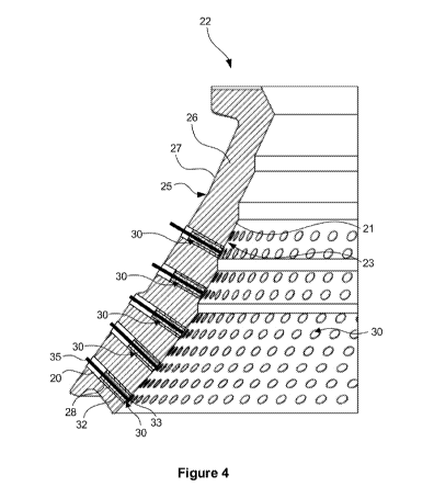
[0065] Figure 4 is a cross sectional view of a part of a second embodiment of
a wear sensing
liner configured as a bowl liner of a cone crusher;
[0066] Figure 5 shows a cross sectional view of a part of a third embodiment
of a wear
sensing liner configured as a mantle liner of a cone crusher;
[0067] Figure 6 shows a cross sectional view of a part of a fourth embodiment
of a wear
sensing liner configured as a jaw liner of a jaw crusher;
[0068] Figure 7 shows a cross sectional view of a part of a fifth embodiment
of a wear
sensing liner configured as a concave liner of a gyratory crusher; and
[0069] Figure 8 shows a block diagram of an embodiment of a wear sensing
system for a
comminution apparatus.
Detailed Description of Exemplary Embodiments
[0070] Figures 1A and 1B illustrate a first embodiment of a sensor 30 for use
in monitoring
wear of a wear sensing liner, as will be described in greater detail below.
The sensor 30 is
configured to sense a physical parameter and to produce a signal indicative of
the physical
parameter being sensed. Examples of the physical parameter sensed include a
depth of the
wear sensing liner in which the sensor is mounted in use, strain, temperature,
pressure,
vibration or the like.
[0071] In all cases, the sensor 30 monitors the physical parameter at a distal
end 33 of the
sensor 30. As will be described in greater detail below, the sensor 30 is a
sacrificial sensor
and degrades over time by being shortened as the wear sensing liner in which
the sensor 30 is
mounted wears in use. Thus, it will be appreciated that the distal end 33 of
the sensor 30 will
transit up towards a proximal end of the sensor 30 with time, i.e. the
effective length of the
sensor 30 is shortened.
[0072] In the embodiment shown in Figures 1A and 1B of the drawings, the
sensor 30 is a
fibre optic sensor and comprises an optical fibre core 35. The optical fibre
core 35 is
configured to transmit and reflect electromagnetic radiation between a first
end and a second
CA 03106357 2021-01-12
WO 2020/210875 PCT/AU2020/050381
end of the optical fibre core 35. The optical fibre core 35 may be an elongate
length of
transparent silica or polymer, for example.
[0073] The optical fibre core 35 is radially surrounded by a protecting
portion, or sheath 37.
The sheath 37 comprises one or more of a cladding with a lower index of
refraction than the
optical fibre core 35, a coating, a strengthening portion configured to
provide strength and/or
rigidity to the optical fibre core, and an outer jacket.
[0074] The sensor 30 comprises a rigid sleeve 32 surrounding the sheath 37.
The sleeve 32
houses at least a portion of the sensor 30. The sleeve 32 is configured to
facilitate mounting
of the sensor 30 within a bore of the wear sensing liner. The sleeve 32 has an
external thread
to enable it to be threadedly engaged with the correspondingly, internally
threaded bore of the
wear sensing liner. In other embodiments (not shown), the sleeve 32 is
configured to be a
press fit or a snap fit in the bore of the wear sensing liner. Further, in
some embodiments (not
shown), the sleeve is 32 is mounted in the bore of the wear sensing liner and
retained in the
bore with an adhesive.
[0075] The sensor 30 is configured to be connected to an electromagnetic
radiation source
(not shown) in the form of a light source. The light may be in the form of
visible light. The
light source generates light and directs the light through the optical fibre
core 35.
[0076] The sensor 30 comprises a plurality of dielectric mirrors 39 arranged
at
longitudinally spaced intervals within the optical fibre core 35. Each
dielectric mirror 39 may
be in the form of an electromagnetic radiation filter, light filter or,
instead, a distributed
reflector. The dielectric mirrors 39 are positioned at known, spaced positions
along the length
of the optical fibre core 35. In other words, the spacing between adjacent
dielectric mirrors
39 is known.
[0077] The dielectric mirrors 39 are evenly spaced along the length of the
optical fibre core
35, as illustrated in Figure 1B. In another embodiment (not shown), the
dielectric mirrors 39
may be irregularly spaced along the length of the optical fibre core 35. For
example, a density
of the dielectric mirrors 39 towards the distal end 33 (a distal density) may
be greater than a
density of the dielectric mirrors 39 towards the other, proximal end (a
proximal density).
Alternatively, the density of the dielectric mirrors 39 towards the distal end
33 may be less
CA 03106357 2021-01-12
WO 2020/210875 PCT/AU2020/050381
11
than the density of the dielectric mirrors 39 towards the other, proximal end.
Increasing the
density of dielectric mirrors 39 improves the resolution of the sensor 30.
[0078] Each dielectric mirror 39 is configured to reflect a specified
wavelength, or a
specified range of wavelengths of light, whilst transmitting the remaining
wavelengths,
thereby producing reflected light. In some embodiments, the wavelength, or
range of
wavelengths of light associated with each dielectric mirror 39 (that is, the
wavelength, or
range of wavelengths reflected by that dielectric mirror 39), differs from the
wavelengths, or
range of wavelengths, of light associated with any other dielectric mirror 39
of the sensor 30.
In other words, each of the dielectric mirrors 39 is configured to reflect a
different specified
wavelength or specified range of wavelengths.
[0079] When the light source directs light through the optical fibre core 35,
each dielectric
mirror 39 reflects a portion of that light. The reflected light forms at least
a part of the signal
produced by the sensor 30. The reflected light comprises a superposition of
the wavelengths
of light reflected by each dielectric mirror 39. The resolution of the sensor
30 therefore
corresponds with the separation of adjacent dielectric mirrors 39.
[0080] As previously described, the sensor 30 is configured to detect wear
along its length
31. As the sensor 30 wears along its length 31, the dielectric mirrors 39 will
also be
sequentially worn away. As each dielectric mirror 39 is worn away, the
reflected light
representative of the superposition of the wavelengths of light reflected by
each dielectric
mirror 39 of the sensor 30 will change. The absence of the specified
wavelength(s) associated
with a particular dielectric mirror 39 contributing to the superposition, and
the known position
of that dielectric mirror 39 along the length of the optical fibre core 35
indicates wear of the
sensor 30 at least to that known position. The wear rate of the sensor 30 can
also be
determined by associating the wear between two or more dielectric mirrors 39
with a
measured time frame.
[0081] In an embodiment, each dielectric mirror 39 is in the form of a fibre
Bragg grating.
That is, the optical fibre core 35 of each sensor 30 contains a plurality of
longitudinally
spaced fibre Bragg gratings positioned at known locations along the length of
the optical fibre
core 35. The inclusion of fibre Bragg gratings in the optical fibre core 35,
causes the
reflection of particular wavelengths of light (the superposition of which
forms a Bragg
CA 03106357 2021-01-12
WO 2020/210875
PCT/AU2020/050381
12
wavelength) while allowing the transmission of the remaining wavelengths. A
reflected peak
is measured and compared to a control peak for variations that can be
attributed to the
physical parameter and/or changes in the physical parameter (e.g. depth or
thickness of the
wear sensing liner, temperature, strain, pressure, vibration, or the like).
[0082] The physical parameter and changes in the physical parameter can be
determined by
measuring the signal comprising the reflected light. The physical parameter
changes can be
determined by measuring the changes in the wavelengths of the reflected light,
or changes in
the superposition of the reflected light, for example, shifts in the Bragg
wavelength. These
changes in the wavelengths of the reflected light, or changes in the
superposition of the
reflected light can then be converted to values representing the physical
parameter. In an
example, the superposition of the reflected light shifts when the respective
sensor 30
encounters a change in temperature, such as an increase in temperature. This
shift can be
detected, and used to determine the change in temperature.
[0083] When multiple fibre Bragg gratings are included in each optical fibre
core 35, each
fibre Bragg grating is configured to reflect different wavelengths of
electromagnetic radiation
as previously described, producing a multiplexed signal. In an example, as the
sensor 30 is
worn away and reduces in length, fibre Bragg gratings are consecutively
destroyed from the
distal end 33 of the optical fibre core 35 of the sensor 30. This leads to a
cessation of their
respective reflected Bragg wavelengths. As the spacing between each fibre
Bragg grating is
known, the extent of wear of the sensor 30 may be easily determined.
Additionally, the wear
rate may be easily determined by associating the extent of wear with a
measured time frame.
[0084] The sensor 30 is advantageously resistant to electromagnetic and radio
frequency
interference. Furthermore, the sensor 30 is resistant to chemicals,
radioactivity, corrosion,
and lightning. The sensor 30 has a high sensitivity, produces a high
resolution signal and is
highly responsive. The sensor 30 can be manufactured in a small form-factor,
and can be
easily connected to other components. The sensor 30 advantageously allows for
the
measurement of wear, temperature, strain and/or pressure via a reduction in
the length 31 of
the sensor 30.
CA 03106357 2021-01-12
WO 2020/210875 PCT/AU2020/050381
13
[0085] Figure 2 illustrates a cross section of another embodiment of the
sensor 30 to sense
the physical parameter. With reference to Figures 1A and 1B, like reference
numerals refer to
like parts unless otherwise specified.
[0086] The sensor 30 comprises a printed circuit board (PCB) 44. The PCB 44
carries a
sensing circuit 42 comprising a plurality of electrical impedance elements,
each in the form of
a resistor, 46, arranged in parallel. Opposed ends 48, 50 of the sensing
circuit 42 are
connected to conductors 49, 51, respectively, for connection to a signal
processing module 61
(illustrated in Figure 8). In some embodiments, the PCB 44 is in the form of a
flexible printed
circuit. The sensor 30 may comprise a power source (not shown), for example, a
battery, that
is configured to power the sensor 30 and to allow the determination of a
characteristic of the
sensing circuit 42.
[0087] Each resistor 46 has a known impedance. The impedance of each resistor
46 may be
the same as each other resistor 46. Alternatively, the impedances of the
resistors 46 may
differ from one another. Each resistor 46 is positioned at a known position
along the length of
the sensor 30. Furthermore, the spacing between adjacent resistors 46 is
known.
[0088] The resistors 46 are evenly spaced along the length of the PCB 44, as
illustrated in
Figure 2. In another embodiment (not shown), the resistors 46 may be
irregularly spaced
along the length of the PCB 44. For example, a density of the resistors 46
towards the distal
end 33 (a distal density) may be greater than a density of the resistors 46
towards the other,
proximal end (a proximal density) of the PCB 44. Alternatively, the density of
the resistors
46 towards the distal end 33 may be less than the density of the resistors 46
at the other end.
Increasing the density of resistors 46 improves the resolution of the sensor
30.
[0089] The sensor 30 comprises the rigid sleeve 32 housing an elongate portion
of the PCB
44. As with the previous embodiment, the sleeve 32 facilitates mounting of the
sensor 30
within a bore of the wear sensing liner. The sleeve 32 has an external thread
to enable it to be
threadedly engaged with the correspondingly, internally threaded bore of the
wear sensing
liner. In other embodiments (not shown), the sleeve 32 is configured to be a
press fit or a
snap fit in the bore of the wear sensing liner. Further, in some embodiments
(not shown), the
sleeve is 32 is mounted in the bore of the wear sensing liner and retained in
the bore with an
adhesive.
CA 03106357 2021-01-12
WO 2020/210875 PCT/AU2020/050381
14
[0090] As previously described, the sensor 30 is configured to produce a
signal indicative of
the physical parameter. As the sensor 30 is worn down by abrasion of the wear
sensing liner
in which it is mounted, the distal most resistor 46 will also be destroyed by
being worn away.
As each distal resistor 46 is worn away, the impedance of the sensing circuit
42 changes. The
impedance of the sensing circuit 42 is therefore indicative of the length of
the sensor 30 and is
therefore also indicative of wear of the sensor 30. Thus, when the impedance
of the sensing
circuit 42 indicates that a particular resistor 46 has been worn away, it is
able to be inferred
that the length of the sensor 30 has worn to at least that known position. The
resolution of the
sensor 30 therefore corresponds with the separation of adjacent resistors 46.
The wear rate of
the sensor 30 can be determined by associating the wear between two or more
resistors 46
with a measured time frame.
[0091] In an embodiment, particularly where the sensor 30 is to communicate
wirelessly, the
sensor 30 comprises a power source (not shown), for example, a battery. As
will be described
in greater detail below, the sensor 30 communicates with a signal processing
module and,
optionally, a wireless communications system. The sensor 30 may wirelessly
transmit a data
set generated by the sensor 30. The complete data set may comprise a
representation of the
signal over time. In order to reduce power consumption, the sensor 30 may
transmit an
indication of a change in the signal and/or the physical parameter when
detected, rather than
transmitting the complete data set generated by the sensor 30. Advantageously,
this
significantly reduces the amount of data transmitted, and the power
consumption of the sensor
30.
[0092] In an embodiment, the sensor 30 is configured to sense an alternative
physical
parameter. For example, the physical parameter sensed may comprise
temperature, strain,
vibration, pressure, or the like. Each impedance element 46 may be in the form
of a
thermistor, a strain gauge, a vibration sensor, or a pressure sensor.
Alternatively, the sensor
30 comprises one or more sensing elements in addition to the impedance
elements 46. The
sensing circuit 42 may comprise each sensing element. Each of the sensing
elements is
positioned at a known position along the length of the sensor 30, as described
with reference
to the impedance elements, and therefore, the sensing elements provide an
indication of the
physical parameter along the length 31 of the sensor 30.
CA 03106357 2021-01-12
WO 2020/210875 PCT/AU2020/050381
[0093] The described sensor 30 advantageously allows for the provision of a
wireless sensor
30 that can be used in difficult to access areas, or components. For example,
the sensor 30
may comprise an antenna for wireless communication with remote units. The
battery powers
the sensing circuit 42 and the antenna, and provides, for example, a 3 to 6
month lifespan,
allowing the sensor to operate without maintenance for an extended period of
time.
[0094] A wear liner is designed and manufactured to be sacrificially worn
instead of the
crushing surface of a comminution apparatus. It is useful for an operator or a
site supervisor
to monitor the extent of wear and/or the wear rate of the wear liner during
its operational life
and to determine when the wear liner requires replacement. Additionally, it is
useful to be
informed of physical parameters that may affect the extent of wear and/or the
wear rate of the
wear liner. It will be appreciated by those skilled in the art that a
reference to a wear liner as
used herein may also apply to a wear plate.
[0095] Figure 3 shows a first embodiment of a wear sensing liner 22. The wear
sensing
liner 22 is configured as a wear plate for a hopper. The wear sensing liner 22
includes a liner
body 26. The wear sensing liner 22 also includes a plurality of sensors 30, as
described
above. The wear sensing liner 22 may comprise, for example, a plurality of the
sensors 30
described with reference to Figures 1A and 1B, a plurality of the sensors 30
described with
reference to Figure 2, or some combination thereof.
[0096] The liner body 26 comprises a plurality of rigid tiles 16. In general,
the tiles 16 are
polygonal, such as rectangular, triangular, hexagonal, or another shape. The
liner body 26
comprises a base 18. Each sensor 30 is received within a hole 20 or opening.
Each hole 20 is
located at a corner of abutting tiles 16. The plurality of holes 20 are formed
during
fabrication of the liner body 26 (e.g. by casting) or, instead, are formed,
for example, by
drilling, after the fabrication of the liner body 26. Each sensor 30 is
received in its associated
hole 20 from an operatively rear surface of the base 18. In this particular
embodiment, each
sensor 30 extends substantially through the entire depth of the liner body 26.
[0097] Figure 4 shows an embodiment of a wear sensing liner 22 for a
comminution
apparatus 90 (Figure 8) in the form of a cone crusher. More particularly, the
wear sensing
liner 22 is for a bowl or shell of the cone crusher. The wear sensing liner 22
comprises a liner
body 26. The liner body 26 comprises a wear surface side 23 and an operatively
rear surface
CA 03106357 2021-01-12
WO 2020/210875 PCT/AU2020/050381
16
side 25. The wear surface side 23 defines a wear surface 21 and the rear
surface side 25
defines a rear surface 27.
[0098] The body 26 of the wear sensing liner 22 defines a plurality of holes
20. Each of the
plurality of holes 20 spans at least a portion of a depth of the liner body
26. In the illustrated
embodiment, each of the plurality of holes 20 spans the entire depth of the
liner body 26.
That is, each of the plurality of holes 20 extends from the wear surface side
23 to the rear
surface side 25 of the liner body 26. Once again, the holes 20 are formed
during fabrication,
for example during casting, of the liner body 26 or, instead, are formed, for
example, by
drilling, after fabrication.
[0099] An insert 28 is received in each hole 20 of the liner body 26 of the
wear sensing liner
22. In an embodiment, each insert 28 is threadedly inserted into a respective
hole 20 of the
liner body 26. Each insert 28 thus provides a securing point for a respective
sensor 30. A
wear surface end (e.g. a distal end) of each insert 28 is flush with the wear
surface 21 of the
liner body 26. As illustrated, one or more of the inserts 28 partially spans
the depth of the
liner body 26, the relevant insert/s 28 terminating short of the rear surface
25 of the liner
body. Instead, one or more of the inserts 28 may span the entire depth of the
liner body 26.
That is, the relevant insert 28 may extend from the wear surface side 23 of
the liner body 26
to the rear surface side 25. Therefore, those inserts 28 may also be flush
with the rear surface
27 of the liner body 26.
[0100] Drilling the holes 20 in the liner body 26 can result in localised
regions of weakness.
Therefore, in some embodiments, each insert 28 is positioned with respect to
the liner body
26 during fabrication of the wear sensing liner 22. For example, the liner
body 26 may be
cast from a castable liner body material. Each insert 28 may be positioned
within a liner body
mould before the liner body 26 is cast. Each insert 28 is configured to melt
at a higher
temperature than the liner body material. For example, each insert 28 may
comprise tungsten
carbide which has a greater than the melting point of the liner body 26
material. The liner
body 26 is therefore able to be cast with each insert 28 in-situ.
[0101] The wear sensing liner 22 comprises a plurality of sensors 30 which are
carried by
the liner body 26. Each sensor 30 is configured to sense wear of the wear
surface side 23 of
the liner body 26 in a region of the respective sensor 30. Each sensor 30 is
further configured
CA 03106357 2021-01-12
WO 2020/210875 PCT/AU2020/050381
17
to degrade in response to wear of the wear surface side 23 of the liner body
26 and, thus, each
sensor 30 functions as a sacrificial sensor.
[0102] The sensors 30 are arranged in an array with respect to the liner body
26, so as to
monitor mechanical degradation across the wear surface side 23 of the liner
body 26. It is
understood that, being arranged in an array, may comprise the sensors 30, for
example, being
positioned in known positions across the liner body 26. The positioning of
each sensor 30 in
the array may be regular, (e.g. a spacing between adjacent sensors 30 may be
consistent), or
may be irregular. For example, a higher density of sensors 30 may be
positioned in regions of
the liner body 26 that are expected to experience the greatest wear, so that
those regions are
able to be better monitored. For example, a lower portion density of the
sensors 30, being the
density of the sensors 30 in an operatively lower portion of the liner body
26, may be greater
than a higher portion density of the sensors 30, being the density of the
sensors 30 in an
operatively higher portion of the liner body 26, or vice versa.
[0103] As described above, each sensor 30 comprises a rigid sleeve 32 housing
at least a
portion of the respective sensor 30. Each sleeve 32 mounts its respective
sensor 30 to the
liner body 26 by being received in an associated insert 28. In an embodiment,
the rigid sleeve
32 has an external thread to enable it to be threadedly engaged within its
associated insert 28.
In other embodiments (not shown), each sleeve 32 may connect to its associated
insert 28
with a press fit or a snap fit. Further, in some embodiments (not shown), each
sleeve 32 may
be secured within its associated insert 28 with an adhesive.
[0104] Each sensor 30 is inserted into the liner body 26 from the operatively
rear surface
side 25 of the liner body 26 by threading the rigid sleeve 32 into its
associated insert 28. Each
sensor 30 is inserted such that a wearing end (i.e., the distal end 33) of
each sensor 30 is
aligned with the wear surface 21 of the liner body 26. The length of each
sensor 30
substantially spans the depth of the liner body 26. Each sleeve 32 has a
proximal end located
at, or towards, the rear surface side 25 of the liner body 26. The proximal
end of each sleeve
32 may lie substantially flush with the rear surface 27 of the liner body 26.
[0105] As previously described, each sensor 30 is operative to produce a
signal
representative of wear of the wear surface side 23 of the liner body 26 by
monitoring a depth
of the liner body 26 in a region of the respective sensor 30. A change in the
signal output by
CA 03106357 2021-01-12
WO 2020/210875 PCT/AU2020/050381
18
any one of the sensors 30 results from mechanical degradation of the wear
surface side 23
around the sensor 30 and, likewise, the respective sensor 30, during operation
of the
comminution apparatus 90.
[0106] As previously described, in an embodiment, the wear sensing liner 22
carries a
plurality of the sensors 30 of Figures 1A and 1B of the drawings. Each of the
sensors 30 is
connected to the light source. Each sensor 30 is positioned at a known
position with respect
to the liner body 26. Therefore, the position of each dielectric mirror 39
with respect to the
liner body 26 is known, as is the position of each dielectric mirror 39 with
respect to the wear
surface 25. The sensor 30 is responsive to wear along its length and,
therefore, is configured
to detect wear of the liner body 26 when carried by the liner body 26.
[0107] As each dielectric mirror 39 is worn away with wear of the wear surface
side 23 of
the liner body 26, the specified wavelength, or range of wavelengths,
reflected by that
dielectric mirror 39 will no longer be reflected. The reflected light, being
the superposition of
the wavelengths of light reflected by each dielectric mirror 39 of the sensor
30 will therefore
also change. The known position of that dielectric mirror 39 along the length
of the optical
fibre core 35 results in the sensor outputting a signal indicative of wear of
the liner body 26 at
least to that known position. The wear rate of the liner body 26 can also be
determined by
associating the wear between two or more dielectric mirrors 39 with a measured
time frame.
As the liner body 26 comprises a plurality of sensors 30, the wear of the
liner body 26 can be
mapped across the wear surface side 23.
[0108] In another example, the superposition of the reflected electromagnetic
radiation (e.g.
the Bragg wavelength) shifts when the respective sensor 30 encounters a change
in
temperature, such as an increase in temperature. The change in temperature may
then be
associated with an external force acting upon the wear sensing liner 22. This
external force is
indicative of mechanical degradation of the liner body 26. Furthermore, the
superposition of
the reflected electromagnetic radiation changes when the sensor 30 is exposed
to a change in
pressure, such as an increase in pressure. The change in pressure may be
determined and may
be associated with an external force acting upon the wear sensing liner 22.
This external force
is again indicative of mechanical degradation of the liner body 26.
Additionally, the
superposition of the reflected light changes when a force is applied to the
sensor 30 causing
strain. The strain may be determined, and may be associated with the force
acting upon the
CA 03106357 2021-01-12
WO 2020/210875 PCT/AU2020/050381
19
wear sensing liner 22. This force is also indicative of mechanical degradation
of the liner
body 26.
[0109] As previously described, in another embodiment, the wear sensing liner
22 comprises
a plurality of the sensors 30 of Figure 2 of the drawings. Each sensor 30 is
positioned at a
known position with respect to the liner body 26. Therefore, the position of
each resistor 46
with respect to the liner body 26 is known, as is the position of each
resistor 46 with respect to
the wear surface 25.
[0110] Each sensor 30 is positioned, in use, in the liner body 26 such that a
distal end of the
PCB 44 of the sensor 30 is aligned with the wear surface 21 of the liner body
26. The PCB 44
is configured to wear with wear of the sensor 30, and, in particular, wear of
the wear surface
side 23 of the liner body 26. The sensor 30 is responsive to wear along its
length and,
therefore, is configured to detect wear of the liner body 26. As previously
described, each
sensor 30 may also be configured to sense one or more of temperature, strain,
pressure or
vibration. Therefore, each sensor 30 is configured to detect the temperature,
strain, pressure
or vibration associated with the liner body 26 in the region of the sensor 30.
This
measurement is indicative of wear of the liner body 26 in the region of the
respective sensor
30.
[0111] The sensing circuit 42 is monitored by, for example, measuring a
potential
difference, current and/or impedance between the ends 48 and 50 of the sensing
circuit 42.
As the sensor 30 degrades in response to wear of the wear surface side 23 of
the liner body
26, the sensing circuit 42 also degrades. In particular, the resistors 46 are
sequentially worn
away altering the overall impedance of the circuit 42 as each resistor 46 is
destroyed.
Therefore, the change in the impedance indicates degradation of the respective
sensor 30, and
thus wear of the wear surface side 23 of the liner body 26. The wear rate of
the liner body 26
can be determined by associating the wear between two or more resistors 46
with a measured
time frame. As the liner body 26 comprises a plurality of sensors 30, the wear
of the liner
body 26 can be mapped across the wear surface side 23.
[0112] The wear sensing liner 22 is associated with a data recorder 60 (shown
in Figure 8).
Each sensor 30 is connected to the data recorder 60. The data recorder 60 is
configured to
CA 03106357 2021-01-12
WO 2020/210875
PCT/AU2020/050381
record the signal from each sensor 30 for transmission to a computing device
62 which may
be a remote device.
[0113] The data recorder 60 comprises a processor 64, for processing software
instructions,
and a memory 66. The processor 64 is configured to execute instructions 68
stored in the
memory 66 to cause the data recorder 60 to perform certain functionality, as
described in
more detail below. The instructions 68 may be in the form of program
instructions or
instruction program code. The processor 64 comprises a microprocessor, central
processing
unit (CPU), application specific instruction set processor (ASIP), application
specific
integrated circuit (ASIC) or another processor capable of reading and
executing instructions.
The memory 66 comprises one or more volatile or non-volatile memory types for
storing
recorded data. For example, memory 66 may comprise one or more of random
access
memory (RAM), read-only memory (ROM), electrically erasable programmable read-
only
memory ([[PROM) or flash memory.
[0114] The data recorder 60 is further configured to be ruggedized, allowing
the data
recorder 60 to operate reliably in harsh environments and conditions.
Furthermore, the data
recorder 60 may be configured to receive and record the signal from each
sensor 30 in real
time or near real time. This allows for the provision of a continuous data
stream that is
representative of in situ use of the wear sensing liner 22, as well as a set
of historic data for
reference.
[0115] The data recorder 60 comprises a network interface 72. The network
interface 72
allows the data recorder 60 to communicate with the computing device 62 over a
communications network 74. Examples of a suitable communications network 74
include a
cloud server network, wired or wireless connection (such as an Internet
connection),
BluetoothIm, Zigbee, or other near field radio communication technology,
and/or physical
media such as USB.
[0116] In an embodiment, the network interface 72 comprises an antenna (not
shown). The
antenna is configured to wirelessly transmit the signal from each sensor 30 to
the computing
device 62. In such embodiments, the computing device 62 is a remote, wireless
device. The
antenna is configured to transmit the signal according to any one of the
wireless technology
standards, such as Bluetooth , Zigbee, IEEE 802.11ac, or the like.
CA 03106357 2021-01-12
WO 2020/210875 PCT/AU2020/050381
21
[0117] As illustrated in Figure 8, and as described above, the data recorder
60 comprises a
signal processing module 61 forming a part of the processor 64. The signal
processing
module 61 processes signals output by each sensor 30 to enable the processor
64 to determine
the wear rate of the wear surface side 23 of the wear sensing liner 22.
[0118] It will be appreciated by persons skilled in the art that the wear
sensing liner 22 may
be configured to be used with different types of comminution apparatuses (e.g.
crushers), or
for different portions of comminution apparatuses. For example, the wear
sensing liner 22, as
described with reference to Figure 4, may be used as a wear sensing liner of a
jaw crusher.
Figure 5 shows a wear sensing liner 22 configured as a mantle liner for a cone
crusher. Figure
6 shows a wear sensing liner 22 configured as a jaw liner for a jaw crusher.
Figure 7 shows a
wear sensing liner 22 configured as a concave liner for a gyratory crusher.
[0119] A comminution apparatus 90 typically includes two crushing surfaces,
one defined
by a stationary component and the other defined by a movable component which
is
displaceable relative to the stationary component. Each component carries wear
sensing
liners 22, of the type described, to protect the components against wear. This
may be the
case, for example, with jaw crushers, cone crushers and gyratory crushers. For
example, in
the case of a cone crusher, the stationary component is the outer bowl or
shell and the
movable component is the cone which rotates eccentrically within the shell.
[0120] Generally, the stationary component of the comminution apparatus 90 is
easier to
access. Thus, the wear sensing liners 22 carried by the stationary component
contain sensors
30 as described above with reference to Figures 1A and 1B of the drawings to
be connected
directly to the light source and associated signal processing circuitry.
Conversely, the
movable component of the comminution apparatus 90 is generally more difficult
to access.
The wear sensing liners 22 associated with the movable component may thus
contain sensors
30 as described above with reference to Figure 2 of the drawings. The sensors
30 associated
with the movable component of the comminution apparatus 90 are able to
communicate
wirelessly with the relevant signal processing circuitry.
[0121] Figure 8 illustrates an embodiment of a wear sensing system 36 which is
operable to
monitor the extent of wear and/or wear rate of the wear sensing liner 22.
CA 03106357 2021-01-12
WO 2020/210875 PCT/AU2020/050381
22
[0122] The wear sensing system 36 comprises the wear sensing liner 22 and a
computing
device 62. In the illustrated embodiment, the computing device 62 is in the
form of a remote
device. It will be appreciated however, that the computing device 62 may be
directly
connected to the wear sensing liner 22 (e.g. by one or more wired
connections). The wear
sensing liner 22, as described above, is arranged to cover or line a crushing
surface of a
comminution apparatus 90. Each sensor 30 of the wear sensing liner 22 is
configured to
produce a signal representative of wear of the wear surface 21 of the liner
body 26. Thus, a
change in the signal output by each sensor 30 in response to mechanical
degradation of the
wear surface 21 during operation of the comminution apparatus 90 is
representative of a
change in the wear surface of the liner body 26.
[0123] The computing device 62 may be in the form of a desktop computer or a
tablet
computer, for example. The computing device 62 comprises a computing device
processor 76
and a computing device memory 78. The computing device processor 76 is
configured to
execute computing device instructions 80 stored in the computing device memory
78 to cause
the computing device 62 to perform certain functionality, as described in more
detail below.
The computing device instructions 80 may be in the form of program
instructions or
instruction program code. The computing device processor 76 comprises a
microprocessor,
central processing unit (CPU), application specific instruction set processor
(ASIP),
application specific integrated circuit (ASIC) or another processor capable of
reading and
executing instructions.
[0124] The computing device memory 78 comprises one or more volatile or non-
volatile
memory types. For example, the computing device memory 78 may comprise one or
more of
random access memory (RAM), read-only memory (ROM), electrically erasable
programmable read-only memory ([[PROM) or flash memory.
[0125] The computing device 62 comprises a computing device network interface
82 which
may be in the form of a wireless receiver. The computing device network
interface 82 allows
the computing device 62 to communicate with the data recorder 60 over the
communications
network 74. Where applicable, the computing device network interface 82 also
allows the
computing device 62 to communicate with the comminution apparatus 90 over the
communications network 74.
CA 03106357 2021-01-12
WO 2020/210875 PCT/AU2020/050381
23
[0126] The computing device 62 comprises a user interface 84 via which a user
enters inputs
to the computing device 62 and via which the user is able to monitor wear of
the wear sensing
liner 22. Thus, the user interface 84 comprises one or more user interface
components, such
as one or more of a display device, a haptic display, a keyboard, a mouse, a
camera, a
microphone, buttons, switches, discernible warning elements (such as audible
or visual
warning devices), or the like.
[0127] As illustrated in Figure 8, the computing device 62 comprises a
parameter module
86. The parameter module 86 is configured to determine a rate of change of the
physical
parameter using the data produced by each sensor 30. That is, the parameter
module 86 is
configured to determine the wear rate of the wear sensing liner 22. The
parameter module 86
is configured to determine an estimated remaining lifetime, or time to
failure, of the wear
sensing liner 22 using the data received from the data recorder 60.
[0128] The computing device 62 further comprises an output module 88. The
output
module 88 is configured to generate one or more outputs obtained from
processing the data.
For example, the output module 88 is configured to generate a visual
representation of the
physical parameter, rate of change of the physical parameter, and/or the
estimated remaining
lifetime, or time to failure, of the wear sensing liner 22, as will be
described in more detail
below. The output module 88 is further configured to generate an alarm based
on the
determined physical parameter, rate of change of the physical parameter,
and/or estimated
remaining lifetime, or time to failure, of the wear sensing liner 22. Still
further, the output
module 88 is configured to generate a control signal based on the determined
physical
parameter, rate of change of the physical parameter, and/or estimated
remaining lifetime, or
time to failure, of the wear sensing liner 22.
[0129] In an embodiment, the comminution apparatus 90 includes the wear
sensing liner 22,
as shown in Figure 8. The comminution apparatus 90 thus comprises the wear
sensing system
36. The comminution apparatus 90 comprises a comminution apparatus controller
92. The
comminution apparatus controller 92 controls the comminution apparatus 90. In
particular,
the comminution apparatus controller 92 controls one or more operating
parameters of the
comminution apparatus 90 (e.g. its throughput). The comminution apparatus
controller 92
operates under the control of the computing device 62, which may activate
and/or deactivate
the comminution apparatus 90 upon instruction. The comminution apparatus 90 is
configured
CA 03106357 2021-01-12
WO 2020/210875 PCT/AU2020/050381
24
to communicate with the computing device 62 and/or the data recorder 60 using
the
communications network 74 if necessary.
[0130] As previously described, each sensor 30 is connected to the data
recorder 60, and the
data recorder 60 is configured to record the signal from each sensor 30. In
particular, the data
recorder 60 is configured to receive the signal from one or more of the
sensors 30 as an input.
The data recorder 60 generates wear data from the signal of each sensor 30 and
stores the data
in the memory 64. The data recorder 60 transmits the data to the computing
device 62 over
the communications network 74. The computing device 62 stores the data in the
computing
device memory 78.
[0131] The computing device 62 determines the wear rate of the liner body 26
from the data
extracted from each signal. To determine the wear rate, the computing device
processor 76
determines the depth, or thickness, of the liner body 26 in a region of a
particular sensor 30 at
a first time using the data. The computing device processor 76 executes the
parameter
module 86 to determine the depth of the liner body 26 using the data.
[0132] The computing device processor 76 compares the data to signal reference
data to
determine the depth of the liner body 26. The signal reference data is stored
in the computing
device memory 78. The signal reference data may comprise a signal look-up
table. The
signal look-up table may comprise known signals, or known signal reference
information, and
corresponding values of the depth of the liner body 26. Thus, when a
particular signal is
detected, the data is compared to the signal reference data to determine the
depth of the liner
body 26. The computing device processor 78 stores the determined depth of the
liner body 26
in the computing device memory 78.
[0133] The computing device 62 generates a visual representation of the
determined depth
of the liner body 26 at the first time. The visual representation of depth
may, for example, be
displayed on the user interface 84. More particularly, the output module 88
generates the
visual representation of the depth.
[0134] The computing device processor 76 then determines the depth in the
region of the
sensor 30 at a second time using the data, as previously described with
reference to the depth
determined at the first time.
CA 03106357 2021-01-12
WO 2020/210875 PCT/AU2020/050381
[0135] The computing device 62 generates a visual representation of the
determined depth
of the liner body 26 at the second time which, once again, may be displayed on
the user
interface 84.
[0136] The computing device processor 76 determines the wear rate of the liner
body 26,
and therefore of the wear sensing liner 22 in the region of the sensor 30 by
comparing the
depth determined at the first time to the depth determined at the second time.
The computing
device 62 generates a visual representation of the determined wear rate of the
liner body 26
which may be displayed on the user interface 84.
[0137] When the wear or wear rate of the liner body 26 reaches, or breaches, a
threshold
level, the computing device 62 generates an alarm, via the output module 88.
The alarm is a
discernible alarm and may comprise a visual alarm output, for example,
displayed on the user
interface 84 and/or an audio alarm. The computing device processor 76 thus
compares the
determined wear and/or wear rate to the relevant threshold level and causes
the alarm to be
generated when the wear is equal to or less than a wear threshold level or the
wear rate is
equal to or greater than a wear rate threshold level.
[0138] The wear of the liner body 26 may correspond to the determined depth of
the liner
body 26, and the threshold level may be a minimum allowable depth of the liner
body 26. If
the liner body 26 were to be allowed to wear beyond the minimum allowable
depth, damage
may be caused to the comminution apparatus 90 on which the wear sensing liner
22 is
installed. Therefore, by generating the alarm when the wear is equal to or
less than the wear
threshold, the computing device 62 notifies the user that the liner body 26
depth is equal to or
less than the wear threshold. Furthermore, by generating the alarm when the
wear rate is
equal to or greater than the wear rate threshold, the computing device 62
notifies the user that
the wear rate of the liner body 26 will result in a reduced lifetime of the
wear sensing liner 22.
The user may, for example, deactivate the comminution apparatus 90, or adjust
an operating
parameter of the comminution apparats 90 based on this alarm, thereby
mitigating damage to
the comminution apparatus 90.
[0139] Wear sensing liners 22 may be difficult to acquire on short notice, and
may require
significant planning to replace. This is because the comminution apparatus 90
is shut down to
facilitate replacement of the wear sensing liner 22. By generating the alarm,
the computing
CA 03106357 2021-01-12
WO 2020/210875
PCT/AU2020/050381
26
device 62 provides advance notice that the wear sensing liner 22 is going need
to be replaced.
This can allow the user sufficient time to plan a shutdown of the comminution
apparatus 90 to
replace the wear sensing liner 22. This minimises the operational disruption
of the
deactivation, by allowing the user to redirect rock material to other
comminution apparatuses,
or stockpile rock material efficiently during the deactivation.
[0140] In addition, or instead, the computing device 62 generates and
transmits a control
signal configured to control the comminution apparatus 90 when the wear and/or
wear rate
reaches, or breaches, the relevant threshold level. The computing device 62
may transmit the
control signal to the comminution apparatus controller 92. The control signal
may deactivate
the comminution apparatus 90. Alternatively, the control signal may adjust an
operating
parameter of the comminution apparatus 90. For example, the control signal may
be
configured to cause a reduction in the throughput of the comminution apparatus
90. As
previously described, this advantageously mitigates damage to the comminution
apparatus 90.
[0141] The computing device 62 is configured to determine an estimated
remaining lifetime
of the liner body 26, and therefore of the wear sensing liner 22. The
estimated remaining
lifetime may also be referred to as the estimated time to failure of the wear
sensing liner 22.
The computing device 62 uses the determined wear and/or wear rate of the liner
body 26 to
determine the estimated remaining lifetime of the wear sensing liner 22.
[0142] The computing device 62 generates a visual representation of the
estimated
remaining lifetime of the wear sensing liner 22 which is displayed on the user
interface 84.
Further, the computing device 62 generates an alarm based on the determined
estimated
remaining lifetime. The computing device 62 generates the alarm when the
determined
estimated remaining lifetime is equal to or less than a lifetime threshold.
The alarm may
comprise a visual alarm output, for example, displayed on the user interface
84 and/or an
audio alarm. In an embodiment, the computing device 62 generates and transmit
a control
signal to control the comminution apparatus 90 when the determined estimated
remaining
lifetime is equal to or less than the lifetime threshold. In particular, the
computing device 62
may transmit the control signal to the comminution apparatus controller 92
either to
deactivate the comminution apparatus 90 or to adjust an operating parameter of
the
comminution apparatus 90. For example, the control signal may be configured to
cause a
CA 03106357 2021-01-12
WO 2020/210875
PCT/AU2020/050381
27
reduction in the throughput of the comminution apparatus 90. As previously
described, this
advantageously mitigates damage to the comminution apparatus 90.
[0143] Although determining the depth of the liner body 26 in the region of
the sensor 30,
the wear of the liner body 26, the wear rate of the liner body 26 and the
estimated remaining
lifetime of the liner body 26 have been described with reference to the signal
produced by the
sensor 30 being representative of the length of the sensor 30, it will be
appreciated that one or
more of these can also be determined where the signal produced by the sensor
30 is indicative
of the temperature at the distal end 33 of the sensor 30 or at an intermediate
portion along the
sensor's 30 length, the strain at the distal end 33 of the sensor 30 or at an
intermediate portion
along the sensor's 30 length, the pressure at the distal end 33 of the sensor
30, the pressure at
an intermediate portion along the sensor's 30 length, vibration at the distal
end 33 of the
sensor 30, or vibration at an intermediate portion along the sensor's 30
length.
[0144] It will be appreciated by persons skilled in the art that numerous
variations and/or
modifications may be made to the above-described embodiments, without
departing from the
broad general scope of the present disclosure. The present embodiments are,
therefore, to be
considered in all respects as illustrative and not restrictive.