Note: Descriptions are shown in the official language in which they were submitted.
CA 03106678 2021-01-15
WO 2020/033162 PCT/US2019/043512
SYSTEMS AND METHODS FOR SUPPORTING MULTIPLE AUTOMATED
WORKFLOWS
CROSS REFERENCE TO RELATED APPLICATION
[0001] The present application claims priority to United States Patent
Application No.
16/045,647, entitled "Systems and Methods for Supporting Multiple Automated
Work-Flows"
filed July 25, 2018, which in turn claims priority to U.S. Provisional Patent
Application No.
62/448,948, filed on January 20, 2017, entitled "Systems and Methods for
Supporting Multiple
Automated Work-Flows and Changing Between Them," each of which is hereby
incorporated by
reference in its entirety.
SEQUENCE LISTING
[0002] The instant application contains a Sequence Listing that has been
submitted
electronically in ASCII format and is hereby incorporated by reference in its
entirety. The
ASCII copy, created on January 22, 2018, is named 120568-5001-WO 5T25.txt and
is 559 bytes
in size.
BACKGROUND
FIELD
[0003] The present disclosure relates to systems and methods for supporting
biological
foundries. More particularly, the present disclosure relates to a systems and
methods for fully
automated workflows using biological foundries.
DESCRIPTION OF RELATED ART
[0004] Electronic devices and components (hereinafter "instruments") have
found numerous
applications in chemistry and biology (more generally, "life sciences"),
especially for detection
CA 03106678 2021-01-15
WO 2020/033162 PCT/US2019/043512
and measurement of various chemical and biological reactions and
identification, detection and
measurement of various compounds, and the synthesis of such compounds, to name
a few
applications. Biological foundries, which comprise lab instruments that are in
electronic
communication with each other, are being increasing used to automate and
handle these
applications. Biological foundries can be complex and expensive. Moreover,
efficient use of
such foundries presents a difficult scheduling problem. For instance, two
different processes
operating at the foundry may need to use the same instrument. Without some
consideration for
scheduling, conflicts may arise where two different processes request the same
instrument.
Moreover, without some consideration for scheduling, the foundry may be under-
utilized, with
the foundry proceeding to process tasks at some form of lowest common
denominator associated
with the foundry.
[0005] During operation of the foundry, instruments must be precisely
controlled in order to
ensure proper use, while research materials require meticulous care in order
to prevent
contamination or spillage. Conventionally, a research scientist is responsible
for manually
handling samples and actively operating instruments. The research scientist
must plan, weigh,
and dispense sample batches; sterilize and wash instruments; and then place
the sample batches
into a variety of instruments. Due to human nature, these sample batches are
often inefficiently
planned, incorrectly weighed, contaminated, or dropped; any one of which may
impair
workflow.
[0006] To consider the depth and complexity that foundries are capable of
handling, consider
the uses of the transcription activator-like effector nuclease (TALENs), which
is a highly
efficient and programmable genome editing tool that has been applied in a wide
range of
organisms (Sun et at., 2012, "Recent advances in targeted genome organic
engineering in
mammalian systems," Biotechnol J 7 (9), p 1074). A TALEN comprises a FokI DNA
cleavage
domain and a DNA binding domain (DBD) that has tandem repeats of a 33-35 amino
acids (aa)
motif The twelfth and thirteenth amino acid residue within each repeat is
known as repeat-
variable di-residue (RVD), and it determines the DNA binding specificity of
the repeat. By
assembling repeats with specific RVDs in order, a TAL effector DBD can bind to
a specific
DNA sequence (Boch, 2011, "TALEs of genome targeting," Nat Biotechnol 29 (2),
p 135).
Because FokI cleavage domain functions as a dimer, TALENs are typically used
in tail-to-tail
heterodimeric pairs to create double stranded breaks for genome editing
(Miller et at., 2011, "A
2
CA 03106678 2021-01-15
WO 2020/033162 PCT/US2019/043512
TALE nuclease architecture for efficient genome editing," Nat Biotechnol 29
(2), p 143). Such
heterodimeric design generates high editing efficiency and improves
specificity, but also presents
challenges in TALEN synthesis as well as usage. A number of methods have been
developed to
synthesize TALEN expression DNA vectors (Briggs et at., 2012, "Iterative
capped assembly:
rapid and scalable synthesis of repeat-module DNA such as TAL effectors from
individual
monomers," Nucleic Acids Res, 40 (15), e117; Reyon et at., 2012, "FLASH
assembly of
TALENs for high-throughput genome editing," Nat Biotechnol, 30 (5), p 460;
Ding et at., 2013,
"A TALEN genome-editing system for generating human stem cell-based disease
models," Cell
Stem Cell, 12(2), p 238; Kim et al., 2013, "A library of TAL effector
nucleases spanning the
human genome," Nat Biotechnol, 31(3), p 251; Schmid-Burgk et at., 2013, "A
ligation-
independent cloning technique for high-throughput assembly of transcription
activator-like
effector genes," Nat Biotechnol, 31(1), p 76).
[0007] Taking advantage of an optimized set of four base-pair junctions as
well as
preassembled di-repeat part library, a one-step assembly scheme was developed
based on the
Golden Gate method using a foundry (Liang et at., 2014, "FairyTALE: A high-
throughput TAL
effector synthesis platform," ACS Synth Biol, 3 (2), p 67). Custom TALEN
vectors could be
constructed in 24 hours at 96% success rate and a material cost of five
dollars. These methods,
however, can only assemble vectors harboring a single TALE-FokI monomer. Since
TALEN
requires a heterodimer to make a cut, two monomers are introduced into the
host cells either on
two separate vectors or a single sub-cloned vector with both monomers. Either
option has
significant drawbacks. For example, both of them will require twice as many
vectors
synthesized as the number of target sequences. When the monomers are on
separate vectors, the
number of cells transfected or transformed with both monomers can be reduced.
More
importantly, the dual vector scheme makes it very difficult to perform high
throughput genetic
screening. Thanks to fluorescence-activated cell sorting (FACS) and next-
generation
sequencing, a large number of cells with different genotypes can be screened
for phenotypes of
interest and sequenced (Shalem et at., 2014, "Genome-scale CRISPR-Cas9
knockout screening
in human cells," Science, 343 (6166), p 84; Wang et at., 2014, "Genetic
Screens in Human Cells
Using the CRISPR-Cas9 System," Science, 343 (6166), p 80). As a precision
genome editing
tool, TALEN can potentially be used to generate a genomic knock-out library.
However,
because the two monomers of each TALEN pair need to be introduced to the same
cell, library
3
CA 03106678 2021-01-15
WO 2020/033162 PCT/US2019/043512
transfection or transformation is not possible using a dual vector system.
Moreover, current
methods to construct a single-vector TALEN require a lengthy and complicated
subcloning
procedure, which makes the synthesis process difficult to scale up. A high-
throughput synthesis
method for single-vector TALENs using a foundry will open up new
possibilities.
[0008] Thus, prior to the present disclosure there existed a need for fully
automated platform to
custom manufacture TALENs in a versatile biological foundry. This is just one
example of the
many needs for improved biological foundries.
[0009] The information disclosed in this Background section is only for
enhancement of
understanding of the general background of the invention and should not be
taken as an
acknowledgement or any form of suggestion that this information forms the
prior art already
known to a person skilled in the art.
BRIEF SUMMARY
[0010] Advantageously, the systems and methods for supporting fully automated
workflows
detailed in the present disclosure address the shortcomings in the prior art
detailed above.
[0011] Transcription activator-like effector nuclease (TALEN) is a
programmable genome
editing tool with wide applications. Since TALENs perform cleavage of DNA as
heterodimers, a
pair of TALENs must be synthesized for each target genome locus.
Conventionally, TALEN
pairs are either expressed on separate vectors or synthesized separately and
then subcloned to the
same vector. Neither approach allows high-throughput construction of TALEN
libraries for
large-scale applications. Here we present a single-step assembly scheme to
synthesize and
express a pair of TALENs in a single transcript format with the help of a P2A
self-cleavage
sequence. Furthermore, we developed a fully automated platform to custom
manufacture
TALENs in a versatile biological foundry. Using the systems and methods of the
present
disclosure, four hundred pairs of TALENs can be synthesized with over 96.2%
success rate at a
reasonable material cost per pair. This platform opens the door to TALEN-based
genome-wide
studies, as well as many other applications in the life sciences.
[0012] Building on our previously published "FairyTALE" protocol (Liang et
at., 2014,
"FairyTALE: A high-throughput TAL effector synthesis platform," ACS Synth
Biol, 3 (2), p 67),
we sought to assemble a pair of TALEN monomers onto a single vector in a one-
step reaction.
In previous work, 2A self-cleavage peptide (Donnelly et at., 2004, "Multiple
gene products from
4
CA 03106678 2021-01-15
WO 2020/033162 PCT/US2019/043512
a single vector: 'self-cleaving' 2A peptides," Gene Ther, 11(23), p 1673; Kim
et at., 2011, "High
Cleavage Efficiency of a 2A Peptide Derived from Porcine Teschovirus-1 in
Human Cell Lines,
Zebrafish and Mice," Plos One, 6 (4)) was used to co-transcribe a pair of
TALENs as one mRNA
molecule but translated as separate functional proteins (Cermak et at., 2015,
"High-frequency,
precise modification of the tomato genome," Genome Biol, 16, p 232; Mariano et
at., 2014,
"Highly efficient genome editing via 2A-coupled co-expression of two TALEN
monomers.
BMC Res Notes, 7, p 628; Xu et at., 2013, "Targeted Myostatin Gene Editing in
Multiple
Mammalian Species Directed by a Single Pair of TALE Nucleases," Mob Ther
Nucleic Acids, 2,
e112). We operationalized this co-expression strategy in a 15-insert one-pot
assembly scheme,
and assembled single-plasmid TALENs in one step at more than 87.7% fidelity.
TALENs
synthesized using this one-step single-transcript design had comparable
cleavage activity in
mammalian cells as those synthesized using a two-plasmid design. We
implemented the
synthesis on iBioFAB (Illinois Biofoundry for Advanced Biomanufacturing), an
integrated and
versatile robotic system, to fully automate the synthesis process. In
accordance with the present
disclosure, four hundred pairs of TALENs can be generated on a daily basis at
a material cost of
$2.1 per pair with minimal human intervention. We envision that genome-wide
studies using
TALENs can be scaled up to screen hundreds of loci in parallel with such a
simplified design
and automated synthesis.
[0013] Accordingly, various aspects of the present disclosure are directed to
providing systems
and methods for supporting multiple automated workflows in a biological
foundry.
[0014] One aspect of the present disclosure provides a non-transitory computer
readable
storage medium for implementing a workflow. The non-transitory computer
readable storage
medium stores instructions, which when executed by a first device, cause the
first device to
obtain a first plurality of organic engineering targets and assign the first
plurality of organic
engineering targets to a first uncompiled workflow. The first uncompiled
workflow is
configured to produce the first plurality of organic engineering targets and
is associated with a
first subset of process modules in a plurality of process modules. Each
respective process
module in the plurality of process modules is associated with a different
subset of unit operation
definitions in a plurality of unit operation definitions. Each respective unit
operation definition
in the plurality of unit operation definitions is independently associated
with a corresponding
time interval. Each respective unit operation definition in the plurality of
unit operations is
CA 03106678 2021-01-15
WO 2020/033162 PCT/US2019/043512
independently associated with a first subset of instruments in a plurality of
instruments (e.g.,
biofoundry).
[0015] The instructions further cause the first device to translate, for each
respective organic
engineering target in the first plurality of organic engineering targets, the
first uncompiled
workflow into a corresponding instance of a compiled first workflow for the
respective organic
engineering target. The corresponding instance of the compiled first workflow
comprises, for
each respective instrument in the first subset of instruments, an address of
the respective
instrument and one or more execution instructions for the respective
instrument, as well as a first
plurality of unit operations. The first plurality of unit operations is
temporally organized into a
linear temporal order. Each respective unit operation in the first plurality
of unit operations is
characterized by the time interval of the corresponding unit operation
definition, thereby forming
a plurality of instances of the compiled first workflow.
[0016] Additionally, the instructions further cause the first device to obtain
a second plurality
of organic engineering targets and to assign the second plurality of organic
engineering targets to
a second uncompiled workflow. The second uncompiled workflow is configured to
produce the
second plurality organic engineering targets and is associated with a second
subset of process
modules in the plurality of process modules. The instructions further cause
the first device to
translate, for each respective organic engineering target in the second
plurality of organic
engineering targets, the second uncompiled workflow into a corresponding
instance of a
compiled second workflow for the respective organic engineering target. The
corresponding
instance of the compiled second workflow comprises for each respective
instrument in the
second subset of instruments an address of the respective instrument and one
or more execution
instructions for the respective instrument, as well as a second plurality of
unit operations. The
second plurality of unit operations is temporally organized into a linear
temporal order. Each
respective unit operation in the second plurality of unit operations is
characterized by the time
interval of the corresponding unit operation definition. A time interval of a
unit operation in the
second plurality of unit operations is adjusted from a time interval of the
corresponding unit
operation definition by an amount in accordance with a determination of an
interlocking
condition with a unit operation in the first compiled workflow, thereby
forming a plurality of
instances of the compiled second workflow.
[0017] In some embodiments, the first or second uncompiled workflow is
selected from the
6
CA 03106678 2021-01-15
WO 2020/033162 PCT/US2019/043512
group consisting of cloning, evolutionary organic engineering, genome organic
engineering,
genotyping, library screening, pathway construction, and protein organic
engineering.
[0018] In some embodiments, the plurality of process modules comprises two or
more process
modules selected from the set of cell culture, DNA assembly, DNA purification,
DNA
quantification, normalization, polymerase chain reaction (PCR), protein
extraction, sample
analysis, sample preparation, sampling, and transformation. In some
embodiments, the plurality
of process modules comprises three or more process modules selected from the
above set of
process modules.
[0019] In some embodiments, the plurality of unit operation definitions
comprises two or more
unit operation definitions from the set of centrifugation, chilled incubation,
chromatography,
colony selection, colony separation, dispensing, electrophoresis,
electroporation, heated
incubation, labelling, magnetic separation, mass spectrometry, peeling,
pipetting, plate reading,
sealing, shaking incubation, spectrophotometry, and thermo-cycling. In some
embodiments, the
plurality of unit operation definitions comprises three or more unit operation
definitions from the
above set of unit operation definitions.
[0020] In some embodiments, the plurality of instruments comprises two or more
instruments
from the set of a liquid handling robot, a temperature controlled block, a
microplate reader, a
chilled incubator, a heated incubator, a shaking incubator, a reagent
dispenser, a plate centrifuge,
a storage carousel, a de-lidding station, a blow-dryer, a plate sealer, a
label printer, a pipetting
device, a shaker, a light box, and a camera. In some embodiments, the
plurality of instruments
comprises three or more instruments from the above set of instruments. In some
embodiments,
the plurality of instruments comprises four or more instruments from the above
set of
instruments. In some embodiments, the plurality of instruments comprises five
or more
instruments from the above set of instruments.
[0021] In some embodiments, the address of the respective instrument comprises
Cartesian
coordinates, polar coordinates, spherical coordinates, joint coordinates, or
tool coordinates of the
respective instrument. In some embodiments, the address of the respective
instrument comprises
a physical location of the respective instrument. In some embodiments, the
address of the
respective instrument comprises a unique electronic address of the respective
instrument.
[0022] In some embodiments, the corresponding instance of the respective
compiled workflow
further comprises an operating condition for the respective instruction.
7
CA 03106678 2021-01-15
WO 2020/033162 PCT/US2019/043512
[0023] In some embodiments, the non-transitory computer readable storage
medium further
stores instructions for enabling a user of the first device, (e.g., via a
graphical user interface), to
adjust the linear temporal order of the first plurality of unit operations. In
some embodiments,
the non-transitory computer readable storage medium further stores
instructions for enabling a
user of the first device to adjust the linear temporal order of the first
plurality of unit operations
without using graphical user interface.
[0024] In some embodiments, the translating further comprises validating the
second plurality
of unit operations according to a predetermined validation list. The
predetermined validation list
comprises one or more criteria of the compiled second workflow. In some
embodiments, the one
or more criteria of the compiled second workflow comprises a priority of each
unit operation in
the second plurality of unit operations, a weight of each unit operation in
the second plurality of
unit operations, a time of completion for the second plurality of unit
operations, a compatibility
of the second plurality of unit operations to a different plurality of unit
operations, a property of
each unit operation in the second plurality of unit operations, and one or
more constraints of the
second plurality of unit operations.
[0025] In some embodiments, the property of each unit operation in the second
plurality of unit
operations is selected from the set of a viscosity value, a purity value, a
composition value, a
temperature value, a weight value, a mass value, and a volume value.
[0026] In some embodiments, the first device is in electronic communication
with at least one
transport path coupled to the plurality of instruments for receiving a sample
from the plurality of
instruments and returning the sample to the plurality of instruments. In some
embodiments, the
transport path comprises at least one transporter configured to move about the
transport path, and
a physical storage medium disposed on the at least one transporter. In some
embodiments, the at
least one transporter comprises a robotic arm, a ground vehicle, a drone, a
conveyor belt, a
transfer station, a lift, a crane, an elevator or a combination thereof In
some embodiments, the at
least one transporter further comprises a liquid handling robot.
[0027] In some embodiments, the second plurality of organic engineering
targets are
determined from outputs of the plurality of instances of the compiled first
workflow.
[0028] In some embodiments, each organic engineering target in the first
plurality of organic
engineering targets is an input into a corresponding instance of a compiled
first workflow in the
plurality of instances of the compiled first workflow.
8
CA 03106678 2021-01-15
WO 2020/033162 PCT/US2019/043512
[0029] In some embodiments, each organic engineering target in the first
plurality of organic
engineering targets is an output of a corresponding instance of a compiled
first workflow in the
plurality of instances of the compiled first workflow.
[0030] In some embodiments, each organic engineering target in the first
plurality of organic
engineering targets is an assembly of nucleic acid components.
[0031] In some embodiments, each organic engineering target in the first
plurality of organic
engineering targets is a plurality of reagents of nucleic acid components.
[0032] In some embodiments, each respective compiled workflow in the plurality
of instances
of the compiled first workflow is a scheme to synthesize and express a pair of
TALENs in a
single transcript format by a P2A self-cleavage sequence. In some embodiments,
at least 400
pairs of TALENs are expressed in a 24-hour time interval.
[0033] In some embodiments, the instructions, when executed by the first
device, further
causes the first device to export the output of a corresponding instance of a
compiled first
workflow to a second device.
[0034] In some embodiments, the first device communicates with at least one
external control
server or an external database server.
[0035] In some embodiments, the instructions, when executed by the first
device, further
causes the first device to save workflow data describing data of the executed
instructions.
[0036] In some embodiments, the non-transitory computer readable storage
medium further
comprises instructions for concurrently executing one or more instances of the
compiled first
workflow and one or more instances of the compiled second workflow.
[0037] In some embodiments, the non-transitory computer readable storage
medium further
comprises instructions for, at each respective time step in a recurring series
of time steps,
simulating a remainder of each of the one or more instances of the compiled
first workflow
thereby forming one or more first simulations. The non-transitory computer
readable storage
medium further comprises instructions for, at each respective time step in a
recurring series of
time steps, simulating a remainder of each of the one or more instances of the
compiled second
workflow thereby forming one or more second simulations. In such embodiments,
the non-
transitory computer readable storage medium further comprises instructions for
firing an
interlocking condition error handler associated with a first unit operation in
an instance of the
one or more instances of the compiled first workflow that forms an
interlocking condition with a
9
CA 03106678 2021-01-15
WO 2020/033162 PCT/US2019/043512
second unit operation in an instance of the one or more instances of the
compiled second
workflow.
[0038] In some embodiments, firing the interlocking condition error handler
adjusts one or
more time intervals of one or more unit operations in an instance of the
compiled first workflow
or an instance of the compiled second workflow that have not been executed.
[0039] In some embodiments, firing the interlocking condition error handler
adjusts a weight
one or more unit operations in an instance of the compiled first workflow or
an instance of the
compiled second workflow that have not been executed as a function of a
priority assigned to the
compiled first workflow versus a priority assigned to the compiled second
workflow.
[0040] In some embodiments, firing the interlocking condition error handler
adjusts one or
more time intervals of one or more unit operations in an instance of the
compiled first workflow
or an instance of the compiled second workflow that have not been executed as
a function of a
priority assigned to the compiled first workflow versus a priority assigned to
the compiled
second workflow.
[0041] In some embodiments, firing the interlocking condition error handler
aborts an instance
of the compiled first workflow or an instance of the compiled second workflow.
[0042] In some embodiments, the interlocking condition error handler is a
mutual exclusion
error handler.
[0043] In some embodiments, the interlocking condition error handler suspends
an instance of
the compiled first workflow or an instance of the compiled second workflow.
[0044] In some embodiments, each time step in the recurring series of time
steps occurs on a
periodic basis.
[0045] In some embodiments, each time step in the recurring series of time
steps occurs
responsive to an occurrence of event in a plurality of event classes. In some
embodiments, the
event class is an instrument error, a power failure, a sample dropping, or an
interlocking
condition.
[0046] In some embodiments, each time step in the recurring series of time
steps occurs every
five minutes. In some embodiments, each time step in the recurring series of
time steps occurs
every 30 seconds, every minute, every 15 minutes, every 30 minutes, or every
hour.
[0047] In some embodiments, the non-transitory computer readable storage
medium further
comprises instructions for concurrently executing two or more instances of the
compiled first
CA 03106678 2021-01-15
WO 2020/033162 PCT/US2019/043512
workflow and two or more instances of the compiled second workflow. In some
embodiments,
the non-transitory computer readable storage medium further comprises
instructions for
concurrently executing three or more instances of the compiled first workflow
and three or more
instances of the compiled second workflow.
[0048] In some embodiments, the non-transitory computer readable storage
medium further
comprises instructions, for each integer kin the set {1, k, . . . , n},
wherein n is a positive
integer of two or greater, to obtain a kth plurality of organic engineering
targets and to assign the
kth plurality of organic engineering targets to a kth uncompiled workflow. The
kth uncompiled
workflow is configured to produce the kth plurality organic engineering
targets, and the kth
uncompiled workflow is associated with a kth subset of process modules in the
plurality of
process modules. The instructions further cause the first device to translate,
for each respective
organic engineering target in the kth plurality of organic engineering
targets, the kth uncompiled
workflow into a corresponding instance of a compiled kth workflow for the
respective organic
engineering target. The corresponding instance of the compiled kth workflow
comprises, for each
respective instrument in the kth subset of instruments, an address of the
respective instrument and
one or more execution instructions for the respective instrument as well as a
kth plurality of unit
operations. The kth plurality of unit operations is temporally organized into
a kth linear temporal
order, and each respective unit operation in the kth plurality of unit
operations is characterized by
the time interval of the corresponding unit operation definition. A time
interval of a unit
operation in the kth plurality of unit operations is adjusted from the
corresponding unit operation
definition by an amount in accordance with a determination of an interlocking
condition with a
unit operation in the first compiled workflow and a unit operation in a second
compiled
workflow, thereby forming a plurality of instances of the compiled kth
workflow.
[0049] In some embodiments, the first subset of instruments comprises two or
more different
instrument classes, and the second subset of instruments comprises two or more
different
instrument classes.
[0050] In some embodiments, a first instrument class and a second instrument
class is used by
both the plurality of instances of the compiled first workflow and the
plurality of instances of the
compiled second workflow. The first instrument class has a first multiplex
value, and the second
instrument class has a second multiplex value, other than the first multiplex
value. Furthermore,
the non-transitory computer readable storage medium stores instructions for
enacting a scheduler
11
CA 03106678 2021-01-15
WO 2020/033162 PCT/US2019/043512
that maximizes a number of instances of the plurality of instances of the
compiled first
workflow, a number of instances of the plurality of instances of the compiled
second workflow,
or a number of instances of a combination of instances of the compiled first
workflow and the
compiled second workflow that can concurrently use instruments of the first
instrument class and
instruments of the second instrument class given the first multiplex value and
the second
multiplex value.
[0051] In some embodiments, the scheduler maximizes, at least in part, by
invoking a first
number of instances of the first instrument class as a function of the first
multiplex value of the
first instrument class and invoking a second number of instances of the second
instrument class
as a function of the second multiplex value of the second instrument class to
be run concurrently
support concurrently running instances of the compiled first workflow and the
compiled second
workflow.
[0052] In some embodiments, the scheduler maximizes, at least in part, by
concurrently
running a first number of instances of the first compiled workflow and a
second number of
instances of the second compiled workflow.
[0053] In some embodiments, the scheduler maximizes, at least in part, by
adjusting, by an
amount, a time interval of a respective unit operation in the first plurality
of unit operations of an
instance of the first compiled workflow from the time interval of the
corresponding unit
operation definition or by adjusting, by an amount, a time interval of a
respective unit operation
in the second plurality of unit operations of an instance of the second
compiled workflow from
the time interval of the corresponding unit operation definition.
[0054] In some embodiments, the method further comprises instructions to
concurrently
execute two or more of the plurality of instances of the compiled first
workflow and two or more
of the plurality of instances of the compiled second workflow.
[0055] In some embodiments, the method further comprises instructions to
concurrently
execute two or more of the plurality of instances of the compiled first
workflow and two or more
of the plurality of instances of the compiled second workflow. In such
embodiments, the first
subset of instruments comprises two or more instruments, the second subset of
instruments
comprises two or more instruments, and at least one instrument in the first
subset of instruments
is in the second subset of instruments.
[0056] In some embodiments, the method further comprises instructions to
concurrently
12
CA 03106678 2021-01-15
WO 2020/033162 PCT/US2019/043512
execute three or more of the plurality of instances of the compiled first
workflow and three or
more of the plurality of instances of the compiled second workflow. In such
embodiments, the
first subset of instruments comprises three or more instruments, the second
subset of instruments
comprises three or more instruments, and at least two instruments in the first
subset of
instruments is in the second subset of instruments.
[0057] In some embodiments, two or more instances of the compiled first
workflow are being
executed at a time when the translating is executed.
[0058] In some embodiments, the non-transitory computer readable storage
medium further
stores instructions for converting a first organic engineering target in the
first plurality of organic
engineering targets into one or more first inputs for the first uncompiled
workflow.
[0059] In some embodiments, the first organic engineering target is synthesis
of a first nucleic
acid and the one or more first inputs for the first uncompiled workflow are a
set of nucleic acid
bases for synthesizing the first nucleic acid.
[0060] In some embodiments, the first uncompiled workflow includes a branch
condition, a
loop condition or a nested condition, and wherein the translating resolves a
value associated with
the branch condition, the loop condition or the nested condition in order to
form the linear
temporal order of the first plurality of unit operations.
[0061] Another aspect of the present disclosure provides methods of
implementing workflows
at a first device comprising one or more processors, memory storing one or
more programs for
execution by the one or more processors, a controller, a communications
interface, a power
supply, and one or more peripheral devices. The one or more programs
singularly or collectively
use the one or more processors to execute a method. The method comprises
obtaining, via the
one or more peripheral devices, a first plurality of organic engineering
targets and assigning, via
the controller, the first plurality of organic engineering targets to a first
uncompiled workflow.
The first uncompiled workflow is configured to produce the first plurality of
organic engineering
targets. The first uncompiled workflow is associated with a first subset of
process modules in a
plurality of process modules. Each respective process module in the plurality
of process
modules is associated with a different subset of unit operation definitions in
a plurality of unit
operation definitions. Each respective unit operation definition in the
plurality of unit operation
definitions is independently associated with a corresponding time interval.
Each respective unit
operation definition in the plurality of unit operations is independently
associated with a first
13
CA 03106678 2021-01-15
WO 2020/033162 PCT/US2019/043512
subset of instruments in a plurality of instruments. The methods further
include translating, via
the controller, for each respective organic engineering target in the first
plurality of organic
engineering targets, the first uncompiled workflow into a corresponding
instance of a compiled
first workflow for the respective organic engineering target. The
corresponding instance of the
compiled first workflow comprises, for each respective instrument in the first
subset of
instruments, an address of the respective instrument and one or more execution
instructions for
the respective instrument, as well as a first plurality of unit operations.
The first plurality of unit
operations is temporally organized into a linear temporal order. Each
respective unit operation in
the first plurality of unit operations is characterized by the time interval
of the corresponding unit
operation definition. In this way, a plurality of instances of the compiled
first workflow are
formed. The methods further comprise obtaining, via the one or more peripheral
devices, a
second plurality of organic engineering targets and assigning, via the
controller, the second
plurality of organic engineering targets to a second uncompiled workflow. The
second
uncompiled workflow is configured to produce the second plurality organic
engineering targets.
The second uncompiled workflow is associated with a second subset of process
modules in the
plurality of process modules. Furthermore, the method includes translating,
via the controller,
for each respective organic engineering target in the second plurality of
organic engineering
targets, the second uncompiled workflow into a corresponding instance of a
compiled second
workflow for the respective organic engineering target. The corresponding
instance of the
compiled second workflow comprises, for each respective instrument in the
second subset of
instruments, an address of the respective instrument and one or more execution
instructions for
the respective instrument, and a second plurality of unit operations. The
second plurality of unit
operations is temporally organized into a linear temporal order. Each
respective unit operation in
the second plurality of unit operations is characterized by the time interval
of the corresponding
unit operation definition. Furthermore, the method includes adjusting, via the
controller, a time
interval of a unit operation in the second plurality of unit operations from a
time interval of the
corresponding unit operation definition by an amount in accordance with a
determination of an
interlocking condition with a unit operation in the first compiled workflow.
In this way, a
plurality of instances of the compiled second workflow are formed.
[0062] Another aspect of the present disclosure provides systems for
implementing workflows
comprising a first device. The first device comprises a display, a power
supply, a
14
CA 03106678 2021-01-15
WO 2020/033162 PCT/US2019/043512
communications interface, one or more peripheral devices, one or more
processors, memory, and
one or more programs non-transiently stored in the memory. The one or more
programs are
configured to be executed by the one or more processors. The one or more
programs include
instructions for obtaining a first plurality of organic engineering targets
and assigning the first
plurality of organic engineering targets to a first uncompiled workflow. The
first uncompiled
workflow is configured to produce the first plurality of organic engineering
targets. The first
uncompiled workflow is associated with a first subset of process modules in a
plurality of
process modules. Each respective process module in the plurality of process
modules is
associated with a different subset of unit operation definitions in a
plurality of unit operation
definitions. Each respective unit operation definition in the plurality of
unit operation definitions
is independently associated with a corresponding time interval. Each
respective unit operation
definition in the plurality of unit operations is independently associated
with a first subset of
instruments in a plurality of instruments. The one or more programs further
include instructions
for translating, for each respective organic engineering target in the first
plurality of organic
engineering targets, the first uncompiled workflow into a corresponding
instance of a compiled
first workflow for the respective organic engineering target. The
corresponding instance of the
compiled first workflow comprises, for each respective instrument in the first
subset of
instruments, an address of the respective instrument and one or more execution
instructions for
the respective instrument, as well as a first plurality of unit operations.
The first plurality of unit
operations is temporally organized into a linear temporal order, and each
respective unit
operation in the first plurality of unit operations is characterized by the
time interval of the
corresponding unit operation definition. In this way, a plurality of instances
of the compiled first
workflow are formed. The one or more programs further include instructions for
obtaining a
second plurality of organic engineering targets and assigning the second
plurality of organic
engineering targets to a second uncompiled workflow. The second uncompiled
workflow is
configured to produce the second plurality organic engineering targets. The
second uncompiled
workflow is associated with a second subset of process modules in the
plurality of process
modules. The one or more programs further include instructions for
translating, for each
respective organic engineering target in the second plurality of organic
engineering targets, the
second uncompiled workflow into a corresponding instance of a compiled second
workflow for
the respective organic engineering target. The corresponding instance of the
compiled second
CA 03106678 2021-01-15
WO 2020/033162 PCT/US2019/043512
workflow comprises, for each respective instrument in the second subset of
instruments, an
address of the respective instrument and one or more execution instructions
for the respective
instrument, as well as a second plurality of unit operations. The second
plurality of unit
operations is temporally organized into a linear temporal order and each
respective unit operation
in the second plurality of unit operations is characterized by the time
interval of the
corresponding unit operation definition. Furthermore, the one or more programs
further include
instructions for adjusting a time interval of a unit operation in the second
plurality of unit
operations from a time interval of the corresponding unit operation definition
by an amount in
accordance with a determination of an interlocking condition with a unit
operation in the first
compiled workflow, thereby forming a plurality of instances of the compiled
second workflow.
[0063] Another aspect of the present disclosure provides methods for
implementing workflows
comprising a first device. The first device comprises a display, a power
supply, a
communications interface, one or more peripheral devices, one or more
processors, memory, and
one or more programs non-transiently stored in the memory. The one or more
programs are
configured to be executed by the one or more processors. The one or more
programs include
instructions for obtaining a first plurality of organic engineering targets
and assigning the first
plurality of organic engineering targets to a first uncompiled workflow. The
first uncompiled
workflow is configured to produce the first plurality of organic engineering
targets. The first
uncompiled workflow is associated with a first subset of process modules in a
plurality of
process modules. Each respective process module in the plurality of process
modules is
associated with a different subset of unit operation definitions in a
plurality of unit operation
definitions. Each respective unit operation definition in the plurality of
unit operation definitions
is independently associated with a corresponding time interval. Each
respective unit operation
definition in the plurality of unit operations is independently associated
with a first subset of
instruments in a plurality of instruments. The one or more programs further
include instructions
for translating, for each respective organic engineering target in the first
plurality of organic
engineering targets, the first uncompiled workflow into a corresponding
instance of a compiled
first workflow for the respective organic engineering target. The
corresponding instance of the
compiled first workflow comprises, for each respective instrument in the first
subset of
instruments, an address of the respective instrument, and one or more
execution instructions for
the respective instrument, as well as a first plurality of unit operations.
The address of the
16
CA 03106678 2021-01-15
WO 2020/033162 PCT/US2019/043512
respective instrument includes a coarse grain address that is associated with
a marker of the
respective instrument. One or more instructions are executed, which includes a
coarse traverse
instruction and a fine traverse instruction. The coarse traverse instruction
commands the
transporter to traverse to the respective marker of the respective instrument.
The fine traverse
instruction commands an articulated handling robot associated with the
transporter to move to at
least one spatial coordinate associated with the respective instrument (e.g.,
to move the
articulated handling robot). The first plurality of unit operations is
temporally organized into a
linear temporal order, and each respective unit operation in the first
plurality of unit operations is
characterized by the time interval of the corresponding unit operation
definition. In this way, a
plurality of instances of the compiled first workflow are formed.
[0064] In some embodiments, the transporter includes a positioning system that
is configured
to locate and guide the transporter within the transport path.
[0065] In some embodiments, the positioning system includes a global
positioning system.
Accordingly, the respective marker of the respective instrument is a global
positioning system
coordinate.
[0066] In some embodiments, the positioning system includes a representation
(e.g., a map) of
a surrounding environment of the transport path. Moreover, in some embodiments
the
representation of the marker positioning of the transport path is either an
image feed or a video
feed, which can have either a low-pass filter or a Gaussian blurring function
is applied to the
representation of the marker positioning of the transport path.
[0067] In some embodiments, the transporter includes an inertial measurement
unit that is
configured to verify and correct each execution of the coarse traverse
instruction of the
respective instruments.
[0068] In some embodiments, the articulated handling robot includes a variety
of sensors.
Each sensor provides information related to a spatial location of the
articulated handling robot
and a surrounding environment of the articulated handling robot.
[0069] In some embodiments, the transporter includes a proportional-integral-
derivative (PD)
controller. The PD controller communicates with the sensors in order to
maintain a spatial
location of the transporter through a control loop.
17
CA 03106678 2021-01-15
WO 2020/033162 PCT/US2019/043512
[0070] In some embodiments, the articulated handling robot transfers a first
tray to a first
instrument using a safety transfer procedure. The safety transfer procedure is
activated, or
enabled, when a readout from the sensors fails to satisfy a threshold
proximity value with respect
to an actual location of the first instrument. The articulated handling robot
activates, or enables,
a default transfer procedure when a readout from the sensors satisfies a
threshold proximity value
with respect to the actual physical location of the first instrument. In some
embodiments, the
threshold proximity value is a distance (e.g., millimeters) or a degree of
rotation/orientation (e.g.,
degrees or Grad), or a combination thereof
[0071] Yet another aspect of the present disclosure provides systems for
implementing
workflows, which includes a first device. The first device includes a display,
a power supply, a
communications interface, and one or more peripheral devices, which includes a
reagent
handling device. The reagent handling device includes a wash manifold, a
primary valve that
regulates an internal flow path in the reagent handling device, and variety of
reagent containers.
Each reagent container includes a valve that controls a flow from the
respective reagent container
to the primary valve. Moreover, the reagent handling device includes a
sterilization container
that holds a sterilizing fluid. Similar to the reagent containers, the
sterilization container includes
a valve that regulates a flow of the sterilization fluid either to the primary
valve or to the wash
manifold. The wash manifold is coupled to the respective valve of each reagent
container, and
regulates the flow of the sterilization fluid from the sterilization container
to the reagent
containers. Furthermore, a dispense manifold is coupled to the primary valve.
The dispense
manifold includes a variety of dispensers, and control a flow from the primary
valve to the
dispensers. The first device also includes one or more processors, memory, and
one or more
programs. The one or more programs are stored in the memory and are configured
to be
executed by the one or more processors. The one or more programs are
configured to be
executed by the one or more processors. The one or more programs include
instructions for
obtaining a first plurality of organic engineering targets and assigning the
first plurality of
organic engineering targets to a first uncompiled workflow. The first
uncompiled workflow is
configured to produce the first plurality of organic engineering targets. The
first uncompiled
workflow is associated with a first subset of process modules in a plurality
of process modules.
Each respective process module in the plurality of process modules is
associated with a different
subset of unit operation definitions in a plurality of unit operation
definitions. Each respective
18
CA 03106678 2021-01-15
WO 2020/033162 PCT/US2019/043512
unit operation definition in the plurality of unit operation definitions is
independently associated
with a corresponding time interval. Each respective unit operation definition
in the plurality of
unit operations is independently associated with a first subset of instruments
in a plurality of
instruments. The one or more programs further include instructions for
translating, for each
respective organic engineering target in the first plurality of organic
engineering targets, the first
uncompiled workflow into a corresponding instance of a compiled first workflow
for the
respective organic engineering target. The corresponding instance of the
compiled first
workflow comprises, for each respective instrument in the first subset of
instruments, an address
of the respective instrument, and one or more execution instructions for the
respective
instrument, as well as a first plurality of unit operations.
[0072] In some embodiments, a pressure regulator is coupled to each of the
sterilization
container, the primary valve, and each reagent container. Furthermore, in some
embodiments
each pressure regulator further includes a filter that prevents contamination.
Moreover, in some
embodiments, each pressure regulator further includes a check valve that
prevents evaporation or
vapor release of a reagent.
[0073] In some embodiments, the reagent handling device includes a pump that
is coupled to
the primary valve. The pump drives the internal flow path of the reagent
handling device.
[0074] In some embodiments, the reagent handling device includes a dispensing
cycle. The
dispensing cycle dispenses a selection of reagents from a set of reagent
containers. In some
embodiments, the reagent handling device includes a first sterilization cycle,
which sterilizes a
portion of the system. Similarly, in some embodiments the reagent handling
device includes a
second sterilization cycle that purges a portion of the system.
[0075] In some embodiments, each component (e.g., each container, valve, etc.)
of the reagent
handling device is coupled through removable tubing.
[0076] In some embodiments, human intervention is only required to replenish a
reagent
container and/or to replenish the sterilization fluid of the sterilization
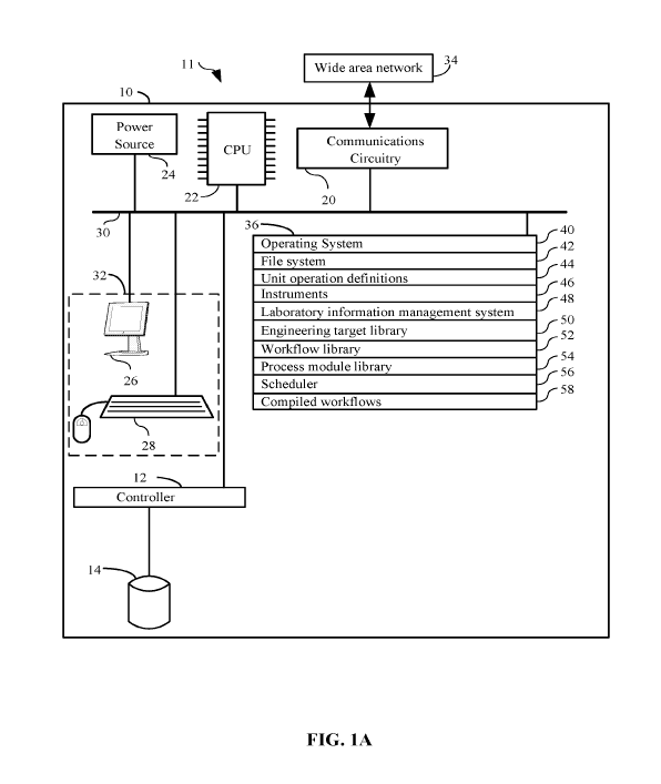
container.
[0077] Yet another aspect of the present disclosure provides methods for
implementing
workflows comprising a first device. The first device comprises a display, a
power supply, a
communications interface, one or more peripheral devices, one or more
processors, memory, and
19
CA 03106678 2021-01-15
WO 2020/033162 PCT/US2019/043512
one or more programs non-transiently stored in the memory. The one or more
programs are
configured to be executed by the one or more processors. The one or more
programs include
instructions for obtaining a first plurality of organic engineering targets
and assigning the first
plurality of organic engineering targets to a first uncompiled workflow. The
first uncompiled
workflow is configured to produce the first plurality of organic engineering
targets. The first
uncompiled workflow is associated with a first subset of process modules in a
plurality of
process modules. Each respective process module in the plurality of process
modules is
associated with a different subset of unit operation definitions in a
plurality of unit operation
definitions. Each respective unit operation definition in the plurality of
unit operation definitions
is independently associated with a corresponding time interval. Each
respective unit operation
definition in the plurality of unit operations is independently associated
with a first subset of
instruments in a plurality of instruments. The one or more programs further
include instructions
for translating, for each respective organic engineering target in the first
plurality of organic
engineering targets, the first uncompiled workflow into a corresponding
instance of a compiled
first workflow for the respective organic engineering target. The
corresponding instance of the
compiled first workflow comprises, for each respective instrument in the first
subset of
instruments, an address of the respective instrument, and one or more
execution instructions for
the respective instrument, as well as a first plurality of unit operations.
The one or more
execution instructions include instructions for a multi-well plate centrifuge
instrument. These
instructions include determining a mass of each multi-well plate in a first
set of multi-well plates.
Each multi-well plate is disposed into the multi-well plate centrifuge.
Furthermore, each
respective multi-well plate has a corresponding counter balance in a set of
counter balances,
which is disposed in the multi-well plate centrifuge at a position opposite
the respective multi-
well plate. Without human intervention, a mass of each respective counter
balance is adjusted to
be equal to the corresponding multi-well plate. The multi-well centrifuge is
then operated. The
first plurality of unit operations is temporally organized into a linear
temporal order, and each
respective unit operation in the first plurality of unit operations is
characterized by the time
interval of the corresponding unit operation definition. In this way, a
plurality of instances of the
compiled first workflow are formed.
[0078] In some embodiments, the first set of multi-well plates is a single
multi-well plate.
CA 03106678 2021-01-15
WO 2020/033162 PCT/US2019/043512
[0079] In some embodiments, the first set of multi-well plates is a set of
from two multi-well
plates to five multi-well plates.
[0080] In some embodiments, the adjusting includes pumping fluid (e.g., water,
mineral oil,
gas) to the respective counter balance in order to adjust the mass therein.
[0081] In some embodiments, the adjusting includes drawing fluid from the
respective counter
balance in order to adjust the mass therein.
[0082] In some embodiments, each counter balance includes a bottom end portion
that is
configured to pool fluid therein.
[0083] In some embodiments, the determining and the adjusting are performed
simultaneously.
[0084] In some embodiments, the adjusting includes storing the adjusted mass
of each counter
balance.
[0085] In some embodiments, the one or more instructions for the multi-well
plate centrifuge
instrument includes determining a mass of each multi-well plate in a second
set of multi-well
plates, disposing each multi-well plate in the second set into the centrifuge,
adjusting, without
human intervention, the mass of each counter balance in a second set of
counter balances to be
equal to the mass of the corresponding multi-well plate in the second set of
multi-well plates, and
operating the multi-well plate centrifuge.
[0086] In some embodiments, the second set of multi-well plates are the first
set of multi-well
plates.
[0087] The automated biological foundry of the present invention has other
features and
advantages that will be apparent from, or are set forth in more detail in, the
accompanying
drawings, which are incorporated herein, and the following Detailed
Description, which together
serve to explain certain principles of exemplary embodiments of the present
invention.
BRIEF DESCRIPTION OF THE DRAWINGS
[0088] FIGS. 1A, 1B, 1C, and 1D illustrate a computer system in accordance
with an
embodiment of the present disclosure;
[0089] FIGS. 2A, and 2B illustrate a system topology and hardware layout in
accordance with
21
CA 03106678 2021-01-15
WO 2020/033162 PCT/US2019/043512
various embodiments of the present disclosure;
[0090] FIGS. 3A, 3B, 3C, 3D, 3E, 3F, 3G, 3H, 31, 3J, 3K, and 3L collectively
illustrate a flow
chart of methods for supporting automated workflows using a first device in
accordance with an
embodiment of the present disclosure, in which optional steps or embodiments
are indicated by
dashed boxes;
[0091] FIG. 4A illustrates an overall design for single-transcript TALEN
synthesis according
to an embodiment of the present disclosure;
[0092] FIG. 4B illustrates an assembly scheme of the design and preliminary
test of single-
transcript TALEN synthesis according to an embodiment of the present
disclosure;
[0093] FIG. 4C illustrates a test assembly of a single-transcript TALEN pair
according to an
embodiment of the present disclosure;
[0094] FIG. 5A illustrates a single-transcript expression of a TALEN pair
according to an
embodiment of the present disclosure;
[0095] FIG. 5B illustrates genome editing in HEK293T cells according to an
embodiment of
the present disclosure;
[0096] FIGS. 5C, 5D, and 5E illustrate disruption of an 0ct4 enhancer in H1
hESC according
to an embodiment of the present disclosure;
[0097] FIGS. 6A and 6B illustrate a breakdown of unit operations of an iBioFAB
system
according to an embodiment of the present disclosure;
[0098] FIGS. 6C and 6D illustrate various control hierarchies of an iBioFAB
system according
to embodiments of the present disclosure;
[0099] FIG. 7A illustrates general workflow for the DNA assembly pipeline
based on Golden
Gate method according to an embodiment of the present disclosure;
[00100] FIG. 7B illustrates a process flow diagram for the build step
according to an
embodiment of the present disclosure;
[00101] FIG. 7C and FIG. 7D illustrate verification of single-transcript
TALENs synthesized in
high throughput according to an embodiment of the present disclosure;
[00102] FIG. 8A and 8B illustrate plasmid design for single plasmid TALEN
assembly
according to an embodiment of the present disclosure;
[00103] FIG. 9A, 9B, 9C, 9D, 9E, 9F, 9G, and 9H illustrate disrupting EGFP in
HEK293 cells
according to an embodiments of the present disclosure;
22
CA 03106678 2021-01-15
WO 2020/033162 PCT/US2019/043512
[00104] FIG. 10 illustrates a Gantt chart for automated Golden Gate DNA
assembly workflow
according to an embodiment of the present disclosure;
[00105] FIG. 11A and FIG. 11B illustrate a list of substrates according to an
embodiment of the
present disclosure;
[00106] FIG. 12 illustrates a list of results from T7E1 assay according to an
embodiment of the
present disclosure;
[00107] FIG. 13 illustrates a fluid management system according to an
embodiment of the
present disclosure;
[00108] FIGS. 14A, 14B, and 14C illustrate a centrifuge compatible vacuum
manifold
according to an embodiment of the present disclosure;
[00109] FIG. 15 illustrates a pipette tip according to an embodiment of the
present disclosure;
[00110] FIGS. 16A and 16B illustrate a dispending pattern and streaking
patterning according to
an embodiment of the present disclosure;
[00111] FIGS. 16C and 16D illustrate another dispending pattern and streaking
patterning
according to an embodiment of the present disclosure;
[00112] FIGS. 17A and 17B illustrate a streaking cone according to an
embodiment of the
present disclosure;
[00113] FIG. 18 illustrates an automated centrifuge handling system according
to an
embodiment of the present disclosure; and
[00114] FIG. 19 illustrates a positioning system according to an embodiment of
the present
disclosure;
[00115] The specific design features of the present invention as disclosed
herein, including, for
example, specific dimensions, orientations, locations, and shapes will be
determined in part by
the particular intended application and use environment.
[00116] In the figures, reference numbers refer to the same or equivalent
parts of the present
invention throughout the several figures of the drawing.
DETAILED DESCRIPTION
[00117] Reference will now be made in detail to various embodiments of the
present
invention(s), examples of which are illustrated in the accompanying drawings
and described
below. While the invention(s) will be described in conjunction with exemplary
embodiments, it
23
CA 03106678 2021-01-15
WO 2020/033162 PCT/US2019/043512
will be understood that the present description is not intended to limit the
invention(s) to those
exemplary embodiments. On the contrary, the invention(s) is/are intended to
cover not only the
exemplary embodiments, but also various alternatives, modifications,
equivalents and other
embodiments, which may be included within the spirit and scope of the
invention as defined by
the appended claims.
[00118] As used herein, in some embodiments, the term "set" means two or more,
three or
more, or four or more.
[00119] It will also be understood that, although the terms first, second,
etc. may be used herein
to describe various elements, these elements should not be limited by these
terms. These terms
are only used to distinguish one element from another. For example, a first
workflow could be
termed a second workflow, and, similarly, a second workflow could be termed a
first workflow,
without departing from the scope of the present disclosure. The first workflow
and the second
workflow are both workflows, but they are not the same workflow.
[00120] The terminology used in the present disclosure is for the purpose of
describing
particular embodiments only and is not intended to be limiting of the
invention. As used in the
description of the invention and the appended claims, the singular forms "a",
"an" and "the" are
intended to include the plural forms as well, unless the context clearly
indicates otherwise. It
will also be understood that the term "and/or" as used herein refers to and
encompasses any and
all possible combinations of one or more of the associated listed items. It
will be further
understood that the terms "comprises" and/or "comprising," when used in this
specification,
specify the presence of stated features, integers, steps, operations,
elements, and/or components,
but do not preclude the presence or addition of one or more other features,
integers, steps,
operations, elements, components, and/or groups thereof.
[00121] In the interest of clarity, not all of the routine features of the
implementations described
herein are shown and described. It will be appreciated that, in the
development of any such
actual implementation, numerous implementation-specific decisions are made in
order to achieve
the designer's specific goals, such as compliance with use case- and business-
related constraints,
and that these specific goals will vary from one implementation to another and
from one designer
to another. Moreover, it will be appreciated that such a design effort might
be complex and
time-consuming, but nevertheless be a routine undertaking of engineering for
those of ordering
skill in the art having the benefit of the present disclosure.
24
CA 03106678 2021-01-15
WO 2020/033162 PCT/US2019/043512
[00122] As used herein, the term "if' may be construed to mean "when" or
"upon" or "in
response to determining" or "in response to detecting," depending on the
context. Similarly, the
phrase "if it is determined" or "if [a stated condition or event] is detected"
may be construed to
mean "upon determining" or "in response to determining" or "upon detecting
[the stated
condition or event]" or "in response to detecting [the stated condition or
event]," depending on
the context.
[00123] In some embodiments, systems and methods for supporting automated
workflows in
accordance with the present disclosure obtain a first set of targets and
assign these targets to a
first uncompiled workflow type. This first uncompiled workflow type is
configured to produce
the targets. Moreover, the first uncompiled workflow comprise process modules
each of which
is further associated with a subset of unit operation definitions. Each unit
operation definition is
associated with a time interval. Each unit operation is further associated
with a subset of
instruments. The present disclosure translates the first uncompiled workflow,
for each target in
the first set of targets, into an instance of a first compiled workflow. The
instance of the first
compiled workflow comprises an address of the instruments and execution
instructions for the
instruments. The unit operations are organized into a linear temporal order.
[00124] The systems and methods of the present disclosure further support
obtaining a set of
second targets and assigning them to an uncompiled second workflow. This
uncompiled second
workflow may be the same or different then the uncompiled first workflow. The
uncompiled
second workflow is configured to produce the second targets. The uncompiled
second workflow
is associated with different process modules from the first uncompiled
workflow. The second
uncompiled workflow is translated into an instance of a compiled second
workflow for each
respective target in the set of second targets. Moreover, a time interval of
unit operations in the
second workflow is adjusted from the corresponding unit operation definition
by an amount in
determination of an interlocking condition with a unit operation in the first
compiled workflow.
In this way, one or more of the second compiled workflows can be executed on
the same foundry
at the same time as one or more of the first compiled workflows are executed.
In fact, in some
embodiments, two or more of the second compiled workflows are executed on the
same foundry
at the same time as two or more of the first compiled workflows.
[00125] In this way, multiple workflows can be run on the same foundry in an
efficient manner.
Although mechanisms for compiling two different types of workflows and running
them on the
CA 03106678 2021-01-15
WO 2020/033162 PCT/US2019/043512
same foundry have been disclosed, the present disclosure is not so limited. In
some
embodiments, two or more instances of three or more, four or more, five or
more, ten or more,
twenty or more, or one hundred or more different types of compiled workflows
are concurrently
run on the same foundry by adjusting the time interval of unit operations in
the respective
workflows to avoid interlocking conditions.
[00126] FIG. 1 details just such an exemplary system 11 for use in supporting
multiple
workflows in a biological foundry. The system preferably comprises a computer
system 10
having:
= a central processing unit (CPU) 22;
= a main non-volatile (non-transitory) storage unit 14, for example a hard
disk
drive, for storing software and data, the storage unit 14 controlled by
storage controller 12;
= a system memory 36, preferably high speed random-access memory (RAM), for
storing system control programs, data, and application programs, comprising
programs and data
loaded from non-volatile storage unit 14; system memory 36 may also include
read-only memory
(ROM);
= a user interface 32, comprising one or more input devices (e.g., keyboard
28, a
mouse) and a display 26 or other output device;
= optionally, a network interface card 20 (communications interface) for
connecting
to any wired or wireless communication network 34 (e.g., a wide area network
such as the
Internet);
= a power source 24 to power the aforementioned elements; and
= an internal bus 30 for interconnecting the aforementioned elements of the
system.
[00127] Operation of computer 10 is controlled primarily by operating system
40, which is
executed by central processing unit 22. Operating system 40 can be stored in
system memory
36. In a typical implementation, system memory 36 also includes:
= a file system 42 for controlling access to the various files and data
structures;
= unit operation definitions 44 which includes execution instructions for a
plurality
of instruments and physical or chemical procedures to impart on the organic
engineering targets
conducted by a single instrument;
= instruments 46 including addresses of each instrument;
= laboratory information management system 48 which includes features
support
26
CA 03106678 2021-01-15
WO 2020/033162 PCT/US2019/043512
modules to manage operations of a laboratory;
= an engineering target library 50 comprising tables of plausible and/or
stored
engineering targets;
= a workflow library 52 comprising a table of predetermined workflows,
workflow
templates, and stored workflows;
= a process module library 54 comprising a table of predetermined process
modules
and stored process modules;
= a scheduler 56 which assists in managing and organizing operations of
workflows; and
= compiled workflows 58 comprising the data of compiled workflows.
[00128] As illustrated in FIG. 1, computer 10 comprises data such as unit
operation definitions
44, engineering target library 50, workflow library 52 and the like. Such data
can be stored in
any form of data storage system including, but not limited to, a flat file, a
relational database
(SQL), or an on-line analytical processing (OLAP) database (MDX and/or
variants thereof). In
some embodiments, as associated data is stored in a single database. In other
embodiments, as
well as associated data is stored in a plurality of databases that may or may
not all be hosted by
the same computer 10. In such embodiments, some components as well as
associated data are
stored on computer systems that are not illustrated by FIG. 1 but that are
addressable by wide
area network 34.
[00129] In some embodiments, unit operation definitions 44 as well as
associated data for such
instruments 46, engineered target library 50, workflow library 52, process
modules 54, and
related software modules illustrated in FIG. 1 are on a single computer (e.g.,
computer 10) and in
other embodiments they are hosted by several computers (not shown). In fact,
all possible
arrangements of unit operation definitions 44, instruments 46, engineered
target library 50,
workflow library 52, process modules 54, and the modules illustrated in FIG. 1
on one or more
computers are within the scope of the present disclosure so long as these
components are
addressable with respect to each other across computer network 34 or by other
electronic means.
Thus, the present disclosure fully encompasses a broad array of computer
systems.
[00130] Now that a system has been described for supporting multiple automated
workflows in
accordance with various exemplary embodiments of the present disclosure,
details regarding
some processes in accordance with FIG. 3 will be disclosed. FIG. 3
collectively illustrates a
27
CA 03106678 2021-01-15
WO 2020/033162 PCT/US2019/043512
flow chart of methods for supporting multiple automated workflows in
accordance with an
exemplary embodiment of the present disclosure. In the flow chart, the
preferred parts of the
methods are shown in solid line boxes whereas optional variants of the
methods, or optional
equipment used by the methods, are shown in dashed line boxes. As such, FIG. 3
illustrates
methods for supporting multiple automated workflows.
[00131] Certain steps are performed by various modules in memory 36. It will
be appreciated
that the steps described in FIG. 3 can be encoded in a single module or any
combination of
modules.
[00132] In describing the methods of FIG. 3, a first workflow and a second
workflow are
described in many embodiments. It should be appreciated, however, that in
accordance with the
present disclosure there can, for each integer kin the set {1, k, , n},
where n is a positive
integer of two or greater, exist n total workflows. Additionally, n refers to
a maximum number
in a given set. Thus a kth workflow is a generic workflow in the set of n
workflows. As such, a
theoretical limit, or bottleneck, to a number of active workflows is a number
of instruments in a
given system or a throughput of a given instrument or class of instruments.
[00133] Referring to blocks 1002-1006 of Figure 3A, a method for implementing
workflows
will now be described. At a first device (e.g., computer 10 of FIG. 1)
comprising one or more
processors, memory storing one or more programs for execution by the one or
more processors, a
controller (e.g., controller 12 of FIG. 1), a communications interface (e.g.,
communications
circuity 20 of FIG. 1), a power supply (e.g., power source 24 of FIG. 1), and
one or more
peripheral devices (e.g., keyboard 28 and display 26 of FIG. 1), the one or
more programs
singularly or collectively executing a given method.
[00134] In some embodiments, the first device communicates with at least one
external control
server or external database server. In some embodiments, data is saved by the
first device which
describes data of the workflow and/or executed instructions. For instance, in
some embodiments
the data is exported as one or more tab delimited files, CSV files, EXCEL
spreadsheets,
GOOGLE Sheets, or in a form suitable for an SQL database. Additionally, such
communication
can be utilized for a plurality of purposes, including, but not limited to,
communicating with first
devices of other systems, saving data of a workflow to an external webserver
or database server,
saving data which describes the executed instructions of instruments, or the
like. Examples of
networks include, but are not limited to, the World Wide Web (WWW), an
intranet and/or a
28
CA 03106678 2021-01-15
WO 2020/033162 PCT/US2019/043512
wireless network, such as a cellular telephone network, a wireless local area
network (LAN)
and/or a metropolitan area network (MAN), and other devices by wireless
communication. The
wireless communication optionally uses any of a plurality of communications
standards,
protocols and technologies, including but not limited to Global System for
Mobile
Communications (GSM), Enhanced Data GSM Environment (EDGE), high-speed
downlink
packet access (HSDPA), high-speed uplink packet access (HSUPA), Evolution,
Data-Only (EV-
DO), HSPA, HSPA+, Dual-Cell HSPA (DC-HSPDA), long term evolution (LTE), near
field
communication (NFC), wideband code division multiple access (W-CDMA), code
division
multiple access (CDMA), time division multiple access (TDMA), Bluetooth,
Wireless Fidelity
(Wi-Fi) (e.g., IEEE 802.11a, IEEE 802.11ac, IEEE 802.11ax, IEEE 802.11b, IEEE
802.11g
and/or IEEE 802.11n), voice over Internet Protocol (VoIP), Wi-MAX, a protocol
for e-mail (e.g.,
Internet message access protocol (IMAP) and/or post office protocol (POP)),
instant messaging
(e.g., extensible messaging and presence protocol (XMPP), Session Initiation
Protocol for Instant
Messaging and Presence Leveraging Extensions (SIMPLE), Instant Messaging and
Presence
Service (IMPS)), and/or Short Message Service (SMS), or any other suitable
communication
protocol, including communication protocols not yet developed as of the filing
date of this
document (1004, 1006).
[00135] Referring to blocks 1008 through 1012 of Figure 3A, the method further
requires
obtaining, via the one or more peripheral devices (e.g., keyboard 28 of FIG.
1), a first plurality of
organic engineering targets. In some embodiments, such as automating workflows
in a
biological foundry, each organic engineering target in the first plurality of
organic engineering
targets is a plurality of reagents of nucleic acid components. In some
embodiments, each
organic engineering target in the first plurality of organic engineering
targets is an assembly of
nucleic acid components. For instance, in some embodiments, each organic
engineering target in
the first plurality of organic engineering targets is a plasmid, and the
nucleic acid components are
predetermined promoters, repressors, stop codon, and exons. In some
embodiments, each
organic engineering target in the first plurality of organic engineering
targets is a different
predetermined nucleic acid with a different predetermined nucleic acid
sequence. In some
embodiments, each organic engineering target in the first plurality of organic
engineering targets
is a different predetermined ribonucleic acid (mRNA) with a different
predetermined nucleic
acid sequence. In some embodiments, each organic engineering target in the
first plurality of
29
CA 03106678 2021-01-15
WO 2020/033162
PCT/US2019/043512
organic engineering targets is a different predetermined deoxyribonucleic acid
(DNA) with a
different predetermined nucleic acid sequence. In some embodiments, each
organic engineering
target in the first plurality of organic engineering targets is a different
predetermined polymer. In
some embodiments, each organic engineering target in the first plurality of
organic engineering
targets is a different predetermined peptide. In some embodiments, each
organic engineering
target in the first plurality of organic engineering targets is a different
predetermined protein.
[00136] In
some embodiments, each organic engineering target in the first plurality of
organic engineering targets comprises a different heteropolymer (copolymer). A
copolymer is a
polymer derived from two (or more) monomeric species, as opposed to a
homopolymer where
only one monomer is used. Copolymerization refers to methods used to
chemically synthesize a
copolymer. Examples of copolymers include, but are not limited to, ABS
plastic, SBR, nitrile
rubber, styrene-acrylonitrile, styrene-isoprene-styrene (SIS) and ethylene-
vinyl acetate. Since a
copolymer consists of at least two types of constituent units (also structural
units, or particles),
copolymers can be classified based on how these units are arranged along the
chain. These
include alternating copolymers with regular alternating A and B units. See,
for example,
Jenkins, 1996, "Glossary of Basic Terms in Polymer Science," Pure Appl. Chem.
68 (12): 2287-
2311, which is hereby incorporated herein by reference in its entirety.
Additional examples of
copolymers are periodic copolymers with A and B units arranged in a repeating
sequence (e.g.
(A-B-A-B-B-A-A-A-A-B-B-B)). Additional examples of copolymers are statistical
copolymers
in which the sequence of monomer residues in the copolymer follows a
statistical rule. If the
probability of finding a given type monomer residue at a particular point in
the chain is equal to
the mole fraction of that monomer residue in the chain, then the polymer may
be referred to as a
truly random copolymer. See, for example, Painter, 1997, Fundamentals of
Polymer Science,
CRC Press, 1997, p 14, which is hereby incorporated by reference herein in its
entirety. Still
other examples of copolymers that may be evaluated using the disclosed systems
and methods
are block copolymers comprising two or more homopolymer subunits linked by
covalent bonds.
The union of the homopolymer subunits may require an intermediate non-
repeating subunit,
known as a junction block. Block copolymers with two or three distinct blocks
are called
diblock copolymers and triblock copolymers, respectively.
[00137] In
some embodiments, each organic engineering target in the first plurality of
organic engineering targets comprises a plurality of polymers, where the
respective polymers in
CA 03106678 2021-01-15
WO 2020/033162
PCT/US2019/043512
the plurality of polymers do not all have the same molecular weight. In such
embodiments, the
polymers in the plurality of polymers fall into a weight range with a
corresponding distribution
of chain lengths. In some embodiments, the polymer is a branched polymer
molecular system
comprising a main chain with one or more substituent side chains or branches.
Types of
branched polymers include, but are not limited to, star polymers, comb
polymers, brush
polymers, dendronized polymers, ladders, and dendrimers. See, for example,
Rubinstein et at.,
2003, Polymer physics, Oxford; New York: Oxford University Press. p. 6, which
is hereby
incorporated by reference herein in its entirety.
[00138] In
some embodiments, each organic engineering target in the first plurality of
organic engineering targets comprises a polypeptide. As used herein, the term
"polypeptide"
means two or more amino acids or residues linked by a peptide bond. The terms
"polypeptide"
and "protein" are used interchangeably herein and include oligopeptides and
peptides. An
"amino acid," "residue" or "peptide" refers to any of the twenty standard
structural units of
proteins as known in the art, which include imino acids, such as proline and
hydroxyproline.
The designation of an amino acid isomer may include D, L, Rand S. The
definition of amino
acid includes nonnatural amino acids. Thus, selenocysteine, pyrrolysine,
lanthionine, 2-
aminoisobutyric acid, gamma-aminobutyric acid, dehydroalanine, ornithine,
citrulline and
homocysteine are all considered amino acids. Other variants or analogs of the
amino acids are
known in the art. Thus, a polypeptide may include synthetic peptidomimetic
structures such as
peptoids. See Simon et at., 1992, Proceedings of the National Academy of
Sciences USA, 89,
9367, which is hereby incorporated by reference herein in its entirety. See
also Chin et at., 2003,
Science 301, 964; and Chin et al., 2003, Chemistry & Biology 10, 511, each of
which is
incorporated by reference herein in its entirety.
[00139] In
some embodiments, each organic engineering target in the first plurality of
organic engineering targets comprises a polypeptide having any number of
posttranslational
modifications. Thus, a polypeptide includes those that are modified by
acylation, alkylation,
amidation, biotinylation, formylation, y-carboxylation, glutamylation,
glycosylation, glycylation,
hydroxylation, iodination, isoprenylation, lipoylation, cofactor addition (for
example, of a heme,
flavin, metal, etc.), addition of nucleosides and their derivatives,
oxidation, reduction,
pegylation, phosphatidylinositol addition, phosphopantetheinylation,
phosphorylation,
pyroglutamate formation, racemization, addition of amino acids by tRNA (for
example,
31
CA 03106678 2021-01-15
WO 2020/033162
PCT/US2019/043512
arginylation), sulfation, selenoylation, ISGylation, SUMOylation,
ubiquitination, chemical
modifications (for example, citrullination and deamidation), and treatment
with other enzymes
(for example, proteases, phosphotases and kinases). Other types of
posttranslational
modifications are known in the art and are also included.
[00140] In
some embodiments, each organic engineering target in the first plurality of
organic engineering targets comprises an organometallic complex. An
organometallic complex
is chemical compound containing bonds between carbon and metal. In some
instances,
organometallic compounds are distinguished by the prefix "organo- " e.g.
organopalladium
compounds. Examples of such organometallic compounds include all Gilman
reagents, which
contain lithium and copper. Tetracarbonyl nickel, and ferrocene are examples
of organometallic
compounds containing transition metals. Other examples include organomagnesium
compounds
like iodo(methyl)magnesium MeMgI, diethylmagnesium (Et2Mg), and all Grignard
reagents;
organolithium compounds such as n-butyllithium (n-BuLi), organozinc compounds
such as
diethylzinc (Et2Zn) and chloro(ethoxycarbonylmethyl)zinc (C1Z,CH2C(=0)0Et);
and
organocopper compounds such as lithium dimethylcuprate (Lr[CuMe2]-). In
addition to the
traditional metals, lanthanides, actinides, and semimetals, elements such as
boron, silicon,
arsenic, and selenium are considered form organometallic compounds, e.g.
organoborane
compounds such as triethylborane (Et3B).
[00141] In
some embodiments, each organic engineering target in the first plurality of
organic engineering targets comprises two different types of polymers, such as
a nucleic acid
bound to a polypeptide. In some embodiments, the polymer includes two
polypeptides bound to
each other. In some embodiments, the polymer under study includes one or more
metal ions
(e.g. a metalloproteinase with one or more zinc atoms) and/or is bound to one
or more organic
small molecules (e.g., an inhibitor). In such instances, the metal ions and or
the organic small
molecules may be represented as one or more additional particles pi in the set
of {pi, ..., pK}
particles representing the native polymer.
[00142] In
some embodiments, each organic engineering target in the first plurality of
organic engineering targets comprises a protein. The basic structural elements
of proteins are
well-known in the art. Nonterminal amino acids typically have the structure -
NH-CUR-CO-,
where R represents an amino acid side chain as is known in the art. Atoms such
as N, C', C and
0 that are not in the sidechain represent backbone atoms. Atoms of the
sidechain, especially the
32
CA 03106678 2021-01-15
WO 2020/033162 PCT/US2019/043512
heteroatoms of the sidechain, are referred to as "terminal" atoms. Thus,
terminal atoms include
CP in alanine, SY in cysteine, and NEl and Cl in tryptophan, for example. Such
terminal atoms
can be unique. C-alpha or C' is the carbon atom in the center of each amino
acid. The protein
backbone includes N, C-alpha, C and 0 atoms. The backbone dihedral angles of
proteins are
called di (phi, involving the backbone atoms C'-N-Ca-C'), w (psi, involving
the backbone atoms
N-Ca-C'-N) and co (omega, involving the backbone atoms Ca-C'-N-Ca). Thus, di
controls the C'-
C' distance, w controls the N-N distance and co controls the Ca-Ca distance.
The planarity of the
peptide bond usually restricts co to be 180 (the typical trans case) or 0
(the rare cis case). The
sidechain dihedral angles tend to cluster near 180 , 60 , and -60 , which are
called the trans,
gauche, and gauche- conformations. The choice of sidechain dihedral angles is
affected by the
neighbouring backbone and sidechain dihedrals. A Ramachandran map
(Ramachandran,
Ramakrishnan, and Sasisekharan 1963) is a representation of the
stereochemically allowed
protein backbone geometries as a function of their variable torsion angles.
[00143] There are different levels of describing the structure of a
protein. Primary
structure refers to the linear sequence of amino acids that make up the
polypeptide chain. The
bond between two amino acids is a peptide bond. The sequence of amino acids
determines the
positioning of the different R groups relative to each other. This positioning
determines the way
that the protein folds and the final structure of the molecule. The secondary
structure of protein
molecules refers to the formation of a regular pattern of twists or kinks of
the polypeptide chain.
The regularity is due to hydrogen bonds forming between the atoms of the amino
acid backbone
of the polypeptide chain. The two most common types of secondary structure are
called the "a-
helix" and "I3-pleated sheet". Tertiary structure refers to the three
dimensional globular structure
formed by bending and twisting of the polypeptide chain. This process often
means that the
linear sequence of amino acids is folded into a compact globular structure.
The folding of the
polypeptide chain is stabilized by multiple weak, noncovalent interactions.
These interactions
include hydrogen bonds, electrostatic interactions, hydrophobic interactions,
and sometimes
covalent bonds. Quaternary structure refers to the fact that some proteins
contain more than one
polypeptide chain, adding an additional level of structural organization: the
association of the
polypeptide chains. Each polypeptide chain in the protein is called a subunit.
The subunits can
be the same polypeptide chain or different ones. For example, the enzyme I3-
galactosidase is a
33
CA 03106678 2021-01-15
WO 2020/033162
PCT/US2019/043512
tetramer, meaning that it is composed of four subunits, and, in this case, the
subunits are identical
- each polypeptide chain has the same sequence of amino acids. Hemoglobin, the
oxygen
carrying protein in the blood, is also a tetramer but it is composed of two
polypeptide chains of
one type (141 amino acids) and two of a different type (146 amino acids).
[0001] In
some embodiments, each organic engineering target in the first plurality of
organic engineering targets comprises a chemical compound that satisfies the
Lipinski rule of
five criteria. In some embodiments, the chemical compound is an organic
compounds that
satisfies two or more rules, three or more rules, or all four rules of the
Lipinski's Rule of Five:
(i) not more than five hydrogen bond donors (e.g., OH and NH groups), (ii) not
more than ten
hydrogen bond acceptors (e.g. N and 0), (iii) a molecular weight under 500
Daltons, and (iv) a
LogP under 5. The "Rule of Five" is so called because three of the four
criteria involve the
number five. See, Lipinski, 1997, Adv. Drug Del. Rev. 23, 3, which is hereby
incorporated
herein by reference in its entirety. In some embodiments, the organic
engineering target satisfies
one or more criteria in addition to Lipinski's Rule of Five. For example, in
some embodiments,
the test perturbation is a compound with five or fewer aromatic rings, four or
fewer aromatic
rings, three or fewer aromatic rings, or two or fewer aromatic rings.
[00144] As such, in the context of biological engineering, an organic
engineering target is one
of the objectives of a research and development project that defines the
desired biological trait to
be achieved. The organic engineering target can be either quantitative or
qualitative. For
example, in one embodiment, an organic engineering target(s) can be a genetic
configuration for
a biosynthetic pathway that produces more compound of interest than a current
level. In another
embodiment, the organic engineering target(s) is a genetic configuration for a
microbial host that
has a tolerance to an inhibitor over X mg/L. Additionally, in some embodiments
an organic
engineering target is a polynucleotide or nucleic acid sequence. The terms
"polynucleotide" and
"nucleic acid sequence" interchangeably refer to a polymer composed of
nucleotide units as
would be understood by one of skill in the art. Preferred nucleotide units
include but are not
limited to those comprising adenine (A), guanine (G), cytosine (C), thymine
(T), and uracil (U).
Useful modified nucleotide units include but are not limited to those
comprising 4-
acetylcytidine, 5-(carboxyhydroxylmethyl)uridine, 2-0-methylcytidine, 5-
carboxymethylaminomethy1-2-thiouridine, 5-carboxymethylamino-methyluridine,
dihydrouridine, 2-0-methylpseudouridine, 2-0-methylguanosine, inosine, N6-
34
CA 03106678 2021-01-15
WO 2020/033162 PCT/US2019/043512
isopentyladenosine, 1-methyladenosine, 1-methylpseudouridine, 1-
methylguanosine, I-
methylinosine, 2,2-dimethylguanosine, 2-methyladenosine, 2-methylguanosine, 3-
methylcytidine, 5-methylcytidine, N6-methyladenosine, 7-methylguanosine, 5-
methylaminomethyluridine, 5-methoxyaminomethy1-2-thiouridine, 5-
methoxyuridine, 5-
methoxycarbonylmethy1-2-thiouridine, 5-methoxycarbonylmethyluridine, 2-
methylthio-N6-
isopentyladenosine, uridine-5-oxyacetic acid-methylester, uridine-5-oxyacetic
acid,
wybutoxosine, wybutosine, pseudouridine, queuosine, 2-thiocytidine, 5-methy1-2-
thiouridine, 2-
thiouridine, 4-thiouridine, 5-methyluridine, 2-0-methyl-5-methyluridine, 2-0-
methyluridine, and
the like. Polynucleotides include naturally occurring nucleic acids, such as
deoxyribonucleic
acid ("DNA") and ribonucleic acid ("RNA"), as well as nucleic acid analogs.
Nucleic acid
analogs include those that include non-naturally occurring bases, nucleotides
that engage in
linkages with other nucleotides other than the naturally occurring
phosphodiester bond or that
include bases attached through linkages other than phosphodiester bonds. Thus,
nucleotide
analogs include, for example and without limitation, phosphorothioates,
phosphorodithioates,
phosphorotriesters, phosphoramidates, boranophosphates, methylphosphonates,
chiral-methyl
phosphonates, 2-0-methyl ribonucleotides, peptide-nucleic acids (PNAs), and
the like.
[00145] Furthermore, in some embodiments an organic engineering target refers
to a
polynucleotide sequence that can be assembled together to form an "engineered
nucleic acid
construct" using the methods of polynucleotide assembly described herein. A
"component
polynucleotide," alternately referred to as "bits" herein, refers to any
isolated or isolatable
molecule of DNA. Useful examples include but are not limited to a protein-
coding sequence,
reporter gene, fluorescent marker coding sequence, promoter, enhancer,
terminator, intron, exon,
poly-A tail, multiple cloning site, nuclear localization signal, mRNA
stabilization signal,
selectable marker, integration loci, epitope tag coding sequence, degradation
signal, or any other
naturally occurring or synthetic DNA molecule. In some embodiments, the DNA
segment is of
natural origin. Alternatively, a DNA segment can be completely of synthetic
origin, produced in
vitro. Furthermore, a DNA segment can comprise any combination of isolated
naturally
occurring DNA molecules, or any combination of an isolated naturally occurring
DNA molecule
and a synthetic DNA molecule. For example, a DNA segment may comprise a
heterologous
promoter operably linked to a protein coding sequence, a protein coding
sequence linked to a
poly-A tail, a protein coding sequence linked in-frame with an epitope tag
coding sequence, and
CA 03106678 2021-01-15
WO 2020/033162 PCT/US2019/043512
the like. Working examples of various organic engineering targets to described
infra (1008,
1010, 1012).
[00146] Referring to block 1014 of Figure 3A, following selection of the first
plurality of
engineering targets, the method includes assigning the first plurality of
organic engineering
targets to a first uncompiled workflow. In general, a workflow is a
generalized laboratory
process that includes a series of unit operations to achieve an engineering
target. Workflows can
be applied to different sample, or organic engineering target, batches with
different parameter
sets. The first uncompiled workflow is configured to produce the first
plurality of organic
engineering targets, and the first uncompiled workflow is associated with a
first subset of process
modules in a plurality of process modules. A process module is a generalized
laboratory process
that consists of a series of unit operations. In most cases, a process module
is routinely
performed in workflows and shared by research projects. When developing
workflows, process
modules can be called from a library (e.g., process module library 54) and
configured with an
appropriate parameter set to simplify and standardize programming practice.
Process modules
can be nested to form complex workflows. For instance, referring to FIG. 6A,
an exemplary
evolutionary engineering workflow is associated with a subset of process
modules including cell
culture and sample, whereas a library screening workflow is associated with
normalization,
transformation, cell culture, and sample process modules. Each respective
process module in the
plurality of process modules is associated with a different subset of unit
operation definitions in a
plurality of unit operation definitions. Each respective unit operation
definition in the plurality
of unit operation definitions is independently associated with a corresponding
time interval as
well as each respective unit operation definition in the plurality of unit
operations is
independently associated with a first subset of instruments in a plurality of
instruments. In the
context of biological engineering, a unit operation is a basic step in a
laboratory process. Unit
operations involve a physical or chemical procedure on the samples conducted
by a single
instrument. In scheduling, a unit operation or action is a largest inseparable
unit that may consist
of a sequence of micro steps (e.g. no other procedure or delay can be cut into
these micro steps).
As shown in FIG. 6A, an exemplary process module "normalization" includes the
unit
operation(s) pipetting, whereas the process module "DNA quantification"
includes unit
operations "spectrophotometry" and "pipetting" (1014).
[00147] Subsets of instruments include but are not limited to systems and/or
devices that
36
CA 03106678 2021-01-15
WO 2020/033162 PCT/US2019/043512
perform unit operations. For instance, referring to FIG. 18, in some
embodiments a subset of
instruments includes an automated centrifuge handling system 1800. The
automated centrifuge
handing system 1800 includes a robotic arm that operates various instruments
of the system and
handles samples.
[00148] In some embodiments, the robotic arm is a Cartesian robotic arm. In
some
embodiments, the robotic arm is an articulated robotic arm, including four
axis robotic arms,
five-axis robotic arms, six-axis robotic arms, and seven-axis robotic arms.
For instance, in some
embodiments the robotic arm is a Kuka KR 3 R540 AGILUS robotic arm or a Kuka
KR 1000
titan F robotic arm. In some embodiments, the robotic arm is a selective
compliance assembly
robot arm (SCARA). In some embodiments, the robotic arm is the previously
described
transporter. In some embodiments, the robotic arm is a conveyer belt, a linear
transfer stage, a
gantry, or an elevator.
[00149] The robotic arm 1802 transfers samples from a storage device 1804 to a
multi-well
plate, or similar device which is utilized by a centrifuge 1818 such as a
vial, a bottle, a screw-top
tube, a snap-top tube, an open tube, a flip-top tube, etc. Once the multi-well
plate, or in some
embodiments a multitude of multi-well plates, is filled, a mass of each multi-
well plate is
determined. In some embodiments, these multi-well plates form a first set of
multi-well plates
(e.g., the multi-well plates of a first operation of the centrifuge). A number
of multi-well plates
in a set of multi-well plates is determined by a type and size of the
centrifuge 1818. For
instance, in some embodiments the centrifuge is configured to hold one multi-
well plate, is
configured to hold two sets of multi-well plates, three sets of multi-well
plates, four sets of multi-
well plates, five sets of multi-well plates, etc. A number of multi-well
plates and a type of multi-
well plate is dictated by a type of centrifuged utilized in the present
disclosure. Accordingly, in
some embodiments the multi-well plates are 6-well plates, are 12-well plates,
are 24-well plates,
are 48 well-plates, are 96-well plates, are 384-well plates, or are 1536-well
plates. Similarly, in
some embodiments these plates are formed with a U-shaped bottom end portion,
with a V-
shaped bottom end portion, or with a flat-shaped bottom end portion. For
instance, in some
embodiments the multi-well plates are Fisherbrand 96-well plates No.:
N95029340FP; are
Thermo Fisher Scientific Nunc U96 Microwell Plates, PS; are Thermo Fisher
Scientific Nunc
V96 Microwell Plates, Clear, PS; are CELLTREAT 96 Well Non-Treated
Microplates, F-
Bottom, Clear, Sterile; are iSci d75-712 Microplates; or are Corning 3370
Plates, 96 well, PS,
37
CA 03106678 2021-01-15
WO 2020/033162 PCT/US2019/043512
Flat, 100/cs, Clear. However, the present disclosure is not limited thereto.
[00150] Centrifuges of the present disclosure include, but are not limited to,
small benchtop
centrifuges, micro-centrifuges (e.g., a microfuge), high speed centrifuges, or
ultra-centrifuges. In
some embodiments, the centrifuge is an Eppendorf 5430 Centrifuge R, an
Eppendorf 5920 R
Centrifuge, a Jouan Robotics GR4 Auto Centrifuge, or a Thermo Fisher
Scientific Heraeus
Multifuge X3 Series Centrifuge. However, the present disclosure is not limited
thereto.
[00151] Each multi-well plate has a corresponding counter balance 1814, which
ensures the
centrifuge 1818 is stable during operation. Without human intervention, a mass
of each counter
balance 1814 is adjusted to be equal to the mass of the corresponding multi-
well plate. This
adjustment is accomplished by pumping fluid (e.g., water, mineral oil, aqueous
solutions, organic
solutions, etc.) from a container 1806, which includes a pressure regulator
1808, or in some
embodiments an air intake, to the counter balance 1814 via a pump 1810. In
some embodiments,
the pump 1808 is a siphon. Attached to the pump is a nozzle, which either
dispenses fluid from
the container 1806 to the counter balance 1814 or draws fluid from the counter
balance 1814 to
the container 1806. In some embodiments, a bottom end portion of each counter
balance 1814 is
formed with a slope to allow the for pooling of the fluid of the container
1806 in the counter
balance 1814. The pooling of the fluid in the counter balance 1814 ensures
that the entire fluid
can be completely removed from the counter balance. In some embodiments, the
slope is
formed as a V-shape, as a U-shape, or as a slant. Moreover, in some
embodiments each counter
balance 1814 is configured to have a relatively low empty mass (e.g., a few
grams) to allow for
higher accuracy and precision in determining a mass of the counter balance
while minimizing
energy consumption required to move the counter balance. Each counter balance
holds a high
internal volume or capacity to ensure that sufficient mass can be added
therein, and a high
tolerance to centrifugal action to ensure that the counter balance survives
operating in the
centrifuge.
[00152] In some embodiments, a multi-well plate and the corresponding counter
balance 1814
are disposed on a balance 1816, or scale, in order to ensure that the masses
of the multi-well
plate and the corresponding counter balance 1814 are equal. This also ensure
that the
measurements are conducted simultaneously. Likewise, in some embodiments the
mass of the
multi-well plate is determined using the scale 1816 and stored for later use.
The multi-well plate
is disposed into the centrifuge 1818 by the robotic arm 1802. The mass of the
corresponding
38
CA 03106678 2021-01-15
WO 2020/033162 PCT/US2019/043512
counter balance is then determined the scale 1816, and adjusted in accordance
with the stored
mass of the multi-well plate. In some embodiments, the mass of the
corresponding counter
balance is stored for later use, such that the adjustment of the mass of the
counter balance in a
later operation of the centrifuge does not require as much of an adjustment
(e.g., adjusting a
previous mass of 20 g to 21 g instead of adjusting a mass of 0 g to 21 g).
Once the mass of the
multi-well plate and the mass of the corresponding counter balance 1814 are
equal, and both
devices are disposed in the centrifuge 1818, the centrifuge is operated.
[00153] In some embodiments, after operating the centrifuge 1818 with the
first set of multi-
well plates and corresponding counter balances 1814, a second set of multi-
well plates are
prepared accordingly. In some embodiments, the second set of multi-well plates
is the first set of
multi-well plates, which were previously sterilized. A mass of each multi-well
plate in this
second set is determined, and masses of corresponding counter balances 1814,
are determined in
accordance with the above descriptions of the first set of multi-well plates
(e.g., determined
simultaneously or consecutively). Accordingly, the utilized automated
centrifuge system of the
present disclosure enables the centrifuge 1818 to be fully operated (e.g.,
multi-well plates are
produced and masses of counter balances are determined and adjusted) without
human
intervention.
[00154] Workflows can include processes for pathway construction, expression
fine-tuning,
genome editing, and cell adaptation but the present disclosure is not limited
thereto. Other
workflows include cloning, evolutionary organic engineering, genome organic
engineering,
genotyping, library screening, pathway construction, and protein organic
engineering (1016).
[00155] Examples of process modules includes, but are not limited to, cell
culture, DNA
assembly, DNA purification, DNA quantification, normalization, polymerase
chain reaction
(PCR), sample preparation, sampling, sample analysis, protein extraction, and
transformation;
however, the present disclosure is not limited thereto. For instance, in other
embodiments, such
as a surgical pathology system or a toxicology system, process modules can
various from system
to system (1018, 1020).
[00156] Examples of unit operations include, but are not limited to,
centrifugation, chilled
incubation, heated incubation, magnetic separation, peeling, pipetting,
dispensing, sealing,
shaking incubation, spectrophotometry, chromatography, mass spectrometry,
microscopic
imagining, electrophoresis, electroporation, clone separation, colony
selection, and thermal
39
CA 03106678 2021-01-15
WO 2020/033162 PCT/US2019/043512
cycling. Other unit operations include freezing, purifying, heating, cryogenic
storage,
sonication, milling, sterilizing, and the like (1022, 1024).
[00157] An instrument is a device that conducts a specific function or
functions in the
automated system. In most cases, an instrument is a device that conducts a
unit operation or unit
operations to samples or organic engineering targets. Examples of instruments
include, but are
not limited to, a centrifuge, a Peltier temperature controller, an incubator,
a shaking incubator, a
magnetic separator, a peeler, a liquid handling robot, a dispenser, a sealer,
a plate reader, a liquid
chromatography system, a gas chromatography system, a mass spectrometry
system, a
microscope, a electrophoresis device, a electroporation device, a clone
separation device, a clone
selection device, and a thermal cycler. FIG. 6B depicts relations between
exemplary unit
operations and a plurality of instruments. Other instruments include, but are
not limited to, fume
hoods, glove boxes, stability chambers, sterilizers, mills, burners, water
baths, coolers, and
similar instruments which are found in scientific laboratories and biological
foundries (1026,
1028).
[00158] For instance, referring to FIG. 13, in some embodiments an instrument
includes a
reagent handling device 1300. The reagent handling device 1300 of the present
disclosure in
configured to store and dispense a variety of reagents (e.g., liquids and/or
gases reagents) for
prolonged periods of time. For instance, if a reagent is honey, which has an
infinite expiration
date, the reagent handling device could store and dispense the honey as long
as there is power
supplied to the robot 1300.
[00159] The reagent handling device 1300 of FIG. 13 includes a primary switch
1302 (e.g., a
primary valve) which is configured as a master control of the robot. Control
of the reagent
handling device 1300 is conducted through one or more pumps (e.g., a multitude
of individual
pumps, a multichannel pump, or a combination thereof), that allows for control
of a dispensing
cycle and a sterilization cycle. The primary switch 1302 is programmatically
controlled to allow
for automated operation of the robot 1300 in a workflow. However, in some
embodiments, the
primary switch 1302 is controlled manually and/or the primary switch 1302 is a
plurality of
selective valves. In some embodiments, the primary switch 1302 includes at
least a first port
1302-1 and a second port 1302-2, which are dedicated ports dedicated to
various cycles of the
reagent handling device 1300, which will be described in more detail infra.
[00160] The dispensing cycle includes a dispense manifold 1310 and a reagent
container
CA 03106678 2021-01-15
WO 2020/033162 PCT/US2019/043512
portion. An inlet of the dispense manifold 1310 is coupled to an outlet of the
primary switch
1302, allowing reagents to flow or traverse from the reagent container portion
to the dispense
manifold. An outlet of the dispense manifold 1310 is coupled to one or more
dispensers 1312.
The present illustration depicts six dispensers (e.g., dispenser 1312-1,
dispenser 1312-2, ...,
dispenser 1312-6). However, the present disclosure is not limited thereto. For
instance, in some
embodiments there exists a one-to-one relation between reagents and dispensers
1312 of the
reagent handling device 1300. In some embodiments, there exists multiple
dispensers 1312 in
order to allow each reagent and combinations thereof to be dispensed through a
dedicated
dispenser 1312.
[00161] Furthermore, in the present illustration there is one connection from
the primary switch
to the dispense manifold. In some embodiments, there are multiple connections
from the
primary switch to the dispense manifold. Multiple connections for a dedicated
connection to the
dispense manifold 1302 for each reagent that the reagent handling device 1300
is configured to
dispense. Each coupling or connection of the reagent handling device 1300 is a
tubing that
allows for a sterile for of reagent therein. In some embodiments, these
connections are
removable.
[00162] The reagent container portion includes a variety of reagent containers
1304 (e.g.,
reagent container 1304-1, reagent container 1304-2, ..., reagent container
1304-6, ... reagent
container 1304-i), each storing a unique reagent. In some embodiments, the
reagent containers
are formed of a sterile material, are sealed from an external environment, are
resistance to
electromagnetic radiation (e.g., ultraviolet light, visible light, infrared
light, etc.), or a
combination thereof Moreover, there is no maximum or minimum number of reagent
containers
1304 that are utilizable by the reagent handling device 1300, since the robot
is configured to
store and dispense any number of reagents.
[00163] In some embodiments, each reagent container 1304 is coupled to a
pressure regulator
1316. The pressure regulator 1316 allows for a control of pressure within the
reagent container
in order to either increase a pressure of the reagent container or decrease
the pressure. Control of
pressure within the reagent container 1304 enables displacement of an internal
reagent with air,
or another fluid. In some embodiments, the pressure regulator 1316 includes an
air filter that
prevents contamination of the reagent container 1304. Air filters should be
appropriately
selected in relation to prevent microbial and particulate contaminants from
entering the reagent
41
CA 03106678 2021-01-15
WO 2020/033162 PCT/US2019/043512
container. In some embodiments, the pressure regulator 1316 includes a check
valve, which
prevents evaporation and/or vapor release of a reagent in the reagent
container 1304.
Furthermore, each reagent container 1304 is coupled to a valve 1314 (e.g., a
selection valve),
which controls a flow of material to/from the reagent container and the
primary valve 1302 or a
wash manifold 1308.
[00164] The sterilization cycle includes the wash manifold 1308 and a
sterilization container
1306. The wash manifold 1308 controls a flow of a sterilization fluid from the
sterilization
container 1306 to each reagent container 1304. In some embodiments, the
sterilization container
is a reagent container 1304 that is dedicated to storing the sterilization
fluid. Sterilization fluids
include liquid chemical sterilants, disinfectants (e.g., high level
disinfectants), distilled water,
detergents, and similar cleaning solutions such as a buffer. In some
embodiments, the
sterilization fluid is a fluid which thermally sterilizes, such as steam. In
some embodiments, the
sterilization fluid is a low temperature gas, vapor, or plasma. The
sterilization container 1306 is
configured in a similar manner as the reagent container 1306, in that a valve
1314 and a pressure
regulator 1316 are coupled thereto.
[00165] While describing the cycles of the liquid handling robot 1300, a first
position of a valve
1314, hereinafter "P1," refers to a valve position 1314-P1 as shown and
described by exemplary
reagent container 1304-5 of FIG 13; a second position of a valve 1314,
hereinafter "P2," refers to
valve position 1314-P2 as shown and described by exemplary reagent container
1304-5 of FIG
13; a third position of a valve, hereinafter "P3," refers to valve position
1314-P3 as shown and
described by exemplary reagent container 1304-5 of FIG 13.
[00166] In some embodiments, the sterilization cycle is a two-part cycle
(e.g., a first
sterilization cycle and a second sterilization cycle). The first cycle is
configured to sterilize
select portions of the reagent handling device 1300 that require, or have
previously required,
attention (e.g., repair or replacement), while the second cycle is configured
to sterilize portions
of the reagent handling device during automated use of the robot.
[00167] In some embodiments, the second cycle is configured to sterilize
select portions of the
reagent handling device 1300 that were recently dispensed or activated, and
purge select portions
of the reagent handling device 1300 with air, gas, distilled water, or a
similar medium.
[00168] While describing the cycles of the liquid handling robot 1300, a first
position of a valve
1314, hereinafter "P1," refers to a valve position 1314-P1 as shown and
described by exemplary
42
CA 03106678 2021-01-15
WO 2020/033162 PCT/US2019/043512
reagent container 1304-5 of FIG 13; a second position of a valve 1314,
hereinafter "P2," refers to
valve position 1314-P2 as shown and described by exemplary reagent container
1304-5 of FIG
13; a third position of a valve, hereinafter "P3," refers to valve position
1314-P3 as shown and
described by exemplary reagent container 1304-5 of FIG 13.
[00169] The first sterilization cycle (e.g., an initial sterilization cycle),
is conducted by selecting
a portion of the reagent handling device 1300 (e.g., reagent container 1304-5)
to sterilize. The
primary valve 1302 is switched to the selected reagent container, the valve
1314 of the selected
reagent container 1304 is switched to P1 and P2 (e.g., P1 open, P2 open, P3
closed), and the
valve 1314 of the selection sterilization container 1306 to P2 and P3. This
first sterilization cycle
allows for, in part, various amounts of sterilization fluid to be dispensed to
a variety of
dispensers 1312 from the sterilization container 1306 through the wash
manifold 1308 to the
selected reagent containers 1304.
[00170] The second sterilization cycle (e.g., an automated sterilization
cycle), is conducted by
switching the primary valve 1302 to the second port 1302-2. This second
sterilization cycle
allows for, in part, various amounts of sterilization fluid to be dispensed to
a variety of
dispensers 1312 from the sterilization container 1306 through the wash
manifold 1308 to the
selected dispensers 1304. To purge the primary valve 1302 and the dispenser
1312, the primary
valve is switch to port one 1302-1, which allows gas or air to be pumped
through portions of the
system.
[00171] The dispensing cycle is conducted by switching each reagent container
1304 to P1 and
P3. The primary valve 1302 is switch to a selected reagent container 1304,
which allows a flow
of material from the selected reagent container to a predetermined dispenser
1312.
[00172] Referring to FIG. 14, in some embodiments the instruments include a
centrifuge
compatible vacuum manifold 1400. The centrifuge compatible vacuum manifold
drives fluid
through a resin or a filter column. As illustrated in FIG. 14, in some
embodiments the centrifuge
vacuum manifold 1400 includes a plate gasket 1402, which seals a portion
(e.g., a top end
portion) of the manifold 1400. The manifold 1400 also includes a channel plug
1404, which
controls and prevents a flow of fluid out of a container body 1406 of the
manifold. The container
body includes one or more fluid channels formed therein, which guide a flow of
fluid towards
the channel plug 1404. In some embodiments, the fluid channels are formed with
a declined
slope on a bottom surface of the container body 1406 to assist a flow of
fluid. The channels of
43
CA 03106678 2021-01-15
WO 2020/033162 PCT/US2019/043512
the container body 1406 are configured to have a first opening of the
container body 1406 be at a
lowest point of the container body, to have at least a portion of one or more
channels at a higher
point than the lowest point of the container body, and have a second opening
at an outside
portion of the container body 1406 that attaches to an external vacuum.
Furthermore, a vacuum
coupler gasket 1408 is coupled to the manifold 1400 to seal the manifold to
the external vacuum,
which rests in a vacuum nest 1410. The vacuum next is removably coupled to the
manifold
1400, and supports, or couples to the external vacuum. In some embodiments,
the manifold
1400 is configured to have a footprint in accordance with guidelines of the
Society for
Biomolecular Screening (SBS). ANSI SLAS 1-2004 (R2012)., the contents of which
are hereby
expressly incorporated by reference. Moreover, in some embodiments the
manifold 1400 is
configured to have a low profile in order to fit the manifold into a variety
of centrifuges and
dispensers. The low profile allows the manifold 1400 to couple to centrifuges
which may have
column arrays attached to thereto. In some embodiments, the vacuum gasket 1408
and the
vacuum nest 1410 have chamfered and/or filleted boundary portions to enable a
fit and
positioning of the container body 1406. As previously described, chamfered
and/or filled
boundary portions of instruments and components thereof is preferred in order
to allow an
automated robot to fit trays, multi-well plates, samples, and the like into
instruments without
yielding a hard collision. For instance, if a tray is misallied by 0.1 mm, and
a fillet has a radius
larger than this misalignment, than the tray will follow the curve of the
fillet and fit into a
receptacle. Furthermore, in some embodiments the vacuum gasket 1408 and the
vacuum nest
1410 are removably coupled to the container body 1406. In some embodiments,
each component
of the manifold 1400 is removably coupled, such that the entire manifold can
be disassembled
into its constituent components. Accordingly, the centrifuge compatible vacuum
manifold 1400
of the present disclosure is operable by a robot arm (e.g., robotic arm 1802
of FIG 18, robotic
arm 1902 of FIG. 19), acts as a vacuum manifold, and stores any fluid dripped
from a column
array until a vacuum is applied.
[00173] Referring to FIGS. 15 through 17, in some embodiments the instruments
include a
clone separate apparatus, which allows for an automated microbial culture
generation. As
illustrated in FIG. 15, a pipette 1500 is utilized to aspirate distilled water
1502, or a similar
buffer or diluent medium, and air 1504, or a similar gas or medium, in an
alternating manner.
These alternative aspirations are repeated a predetermined number of times,
according to a
44
CA 03106678 2021-01-15
WO 2020/033162 PCT/US2019/043512
design of the present disclosure. For instance, in some embodiments, there are
five total
alternations, ten total alternations, twenty total alternations, or fifty
total alternations. In some
embodiments, a volume of each aspiration is uniform (e.g., a volume of
aspiration 1502-1 is
equal to a volume of aspiration 1504-1, which is equal to a volume of
aspiration 1502-2, etc.). In
some embodiments, a volume of each type of aspiration is uniform (e.g., a
volume of aspiration
1502-1 is equal to a volume of aspiration 1502-2, which is equal to a volume
of aspiration 1502-
3, etc.). Furthermore, in some embodiments a volume of each aspiration is non-
uniform (e.g., a
volume of aspiration 1502-1 is not equal to a volume of aspiration 1504-1 or a
volume of
aspiration 1502-2, which is not equal to a volume of aspiration 1502-3, etc.)
Once the final
aspiration of air 1504-i is drawn, a final portion of diluent 1502-Z is
aspirated. However, the
present invention is not limited thereto, as in some embodiments the final
aspiration 1502-Z is
omitted. Finally, a cell culture 1506 is aspirated.
[00174] Referring to FIG. 16, once the contents of the pipette 1500 have been
full aspirated, the
contents are gradually dispensed into a cell culture medium 1602 (e.g., a
petri dish). The
dispensing direction is indicated by an arrow 1604 of FIG. 16A and FIG. 16B.
In some
embodiments, the dispensing direction is a line, a predetermined curve (e.g.,
a sine curve, a
parabolic, a cubic function, etc.), or series of curves (e.g., a parabolic
function coupled to a linear
line). During dispensing of the contents of the pipette 1500, diluent 1502,
air 1504, and the cell
culture 1506 exhibit plug flow. However, the present disclosure is not limited
thereto, as one
skilled in the art may which to exhibit other flow types during dispensing of
the contents of the
pipette 1500. In some embodiments, a density of contents dispensed decreases
as the contents
are dispensed, such that an initial dispensing area has a high density while a
final dispensing area
has a low density. Similarly, in some embodiments the initial dispensing area
has a lower
density while the final dispensing area has a high density.
[00175] Referring to FIG. 17, a streaking cone 1700 is coupled to either the
pipette 1500 or a
similar device through a coupling portion 1706 of the streaking cone. In some
embodiments, the
coupling portion 1706 includes a cavity 1708 configured to receiving the
pipette 1500. The
streaking cone 1700, or a device coupled thereto (e.g., the pipette 1500), is
then moved in a
continuous motion from a first position to a second position. In some
embodiments, the
streaking cone is moved in a first continuous motion from a first position to
a second position,
then in a second continuous motion from a third position to a fourth position.
FIGS. 16B and
CA 03106678 2021-01-15
WO 2020/033162 PCT/US2019/043512
16D illustrate various spiral continuous motions of the streaking cone 1700
according to
embodiments of the present disclosure. However, the present invention is not
limited thereto.
For instance, in some embodiments, the streaking is performed in a concentric
pattern (e.g.,
concentric circles, concentric rectangles, concentric triangles) or in an
array (e.g., an array of
lines, an array of circles, etc.) The continuous motion of the streaking cone
is configured to
spread the dispensed contents of the pipette 1500 using a tip 1702 of the
streaking cone. The tip
1702 of the streaking cone can be designed in a variety of shapes which
promote various spreads
of cell cultures. Furthermore, in some embodiments the streaking cone 1700
includes an elastic,
or flexible, portion 1704 which allows for motion in a vertical axis of the
streaking cone. In the
present illustration, the flexible portion 1704 is formed as type of spring.
However, in some
embodiments, the flexible portion 1704 is formed as a damper or similar energy
absorbing
device. Accordingly, the clone separation apparatus of the present disclosure
enables a full range
of dilution ratios are realized, which guarantees generation of multiple
single colonies.
[00176] In some embodiments, the first device is in electronic communication
with at least one
transport path coupled to the plurality of instruments for receiving a sample
from the plurality of
instruments and returning the sample to the plurality of instruments. The
transport path is
utilized to transfer a sample or organic engineering target from an
instrument, a unit operation, or
a process module to another instrument, unit operation, and/or process module.
In many
embodiments, the transport path allows a given sample or organic engineering
target to traverse
three dimensions in a laboratory without human input. In many embodiments, the
transport path
is the free volume in the system which a transporter can operation
unobstructed. The transport
path can comprise a multi-lane path or a grid of paths (1030).
[00177] In many embodiments, the transport path comprises at least one
transporter configured
to move about the transport path. A physical storage medium, or buffer, is
disposed on the at
least one transporter. The buffer is configured to hold a sample or an organic
engineering target
temporarily to free, or allow, additional operations in the system. For
instance, when a sample
needs to be disposed in an incubator, but said incubator is occupied for 10
minutes and the
instrument said sample was previously disposed requires immediate use by
another second
sample, the original sample can be disposed in the buffer temporarily to free
instruments or arms
of a transporter for further use. In many embodiments, the at least one
transporter comprises a
robotic arm, a ground vehicle, a reduced friction ortho-multilane conduit, a
drone, a conveyor
46
CA 03106678 2021-01-15
WO 2020/033162 PCT/US2019/043512
belt, a transfer station, a lift, a crane, an elevator or a combination
thereof. The present
disclosure is not limited thereto, and many types of transportation devices
can be utilized by a
person skilled in the art of the present disclosure. In many embodiments, the
at least one
transporter comprises a liquid handling robot. In such embodiments, a typical
transporters
configuration requires a first transporter as a general transporter and a
second transport as a
liquid handling robot. Transporters can utilize series or parallel routes, as
well as combination
routing of series and parallel processing routes. These combinations can
reduce travelling times
through optimized flexible routing between unit operations and/or instruments.
Additionally, the
transporter and transport path should be configured to reduce friction, thus
minimizing operating
forces, to increase smoothness of transportation. This decrease a risk of
sample dropping,
spilling, cross contamination and the like. (1032, 1034, 1036).
[00178] The method further requires translating, for each respective organic
engineering target
in the first plurality of organic engineering targets, the first uncompiled
workflow into a
corresponding instance of a compiled first workflow for the respective organic
engineering
target. In general, an uncompiled workflow is a workflow prior to obtaining a
particular sample
input. An instance of a compiled workflow is a single iteration of a workflow
among a plurality
of iterations of said workflow (1038).
[00179] In some embodiments, such as biofoundry, each respective compiled
workflow in the
plurality of instances of the compiled first workflow is a scheme to
synthesize and express a pair
of TALEN in a single transcript format by a P2A self-cleavage sequence (1040).
[00180] In such embodiments, at least 400 pairs of TALENs are expressed in a
24-hour time
interval; however, the present disclosure is not limited thereto. In some
embodiments, at least
200 pairs of TALENs are expressed in a 24-hour time interval, and in another
embodiment at
least 600 pairs of TALENs are expressed in a 24-hour time interval. An exact
number of
completed workflows or expressed organic engineering targets may vary
depending on a number
of environment, workflow, and system conditions (1042).
[00181] In some embodiments, the first organic engineering target in the first
plurality of
organic engineering targets is converted into one or more first inputs for the
first uncompiled
workflow. For instance, when the first organic engineering target is an end
goal or desired
output, such as salt (NaCl), the engineering target is converted into the
reagent components of
that output, such as Sodium (Na) and Chlorine (Cl) (1044).
47
CA 03106678 2021-01-15
WO 2020/033162 PCT/US2019/043512
[00182] In some embodiments, the first organic engineering target is a
synthesis of a first
nucleic acid and the one or more first inputs for the first uncompiled
workflow are a set of
nucleic acid bases for synthesizing the first nucleic acid (1046).
[00183] In some embodiments, the first uncompiled workflow includes a branch
condition, a
loop condition, or nested condition, and the translating resolves the branch
condition, loop
condition or nested condition based on a value associated with the branch
condition, loop
condition or nested condition in order to form the linear temporal order of
the first plurality of
unit operations. In some embodiments, loop conditions are logical criterion to
exit a loop. In
some embodiments, branch conditions are logical criterion to determine the
branch for the
program to proceed at a fork. The logical conditions usually require the input
from the
experiment or workflow itself For example, after running a sample batch in
Process Module A,
when all measurements surpass threshold X, then execute Branch N. (1048).
[00184] Each respective instrument in the first subset of instruments includes
an address of the
respective instrument and one or more execution instructions for the
respective instrument.
Instrument execution instruction(s) are at least parameter sets used in
programming of unit
operations, process modules, and workflows. The instrument execution
instructions sets are the
configurations of machines and process conditions. Such machine configurations
and process
conditions include, but are not limited to, adjusting rotations per minute
(RPM) of a machine,
changing a status of a machine from or to ON and OFF, and the like. Another
interpretation of
instrument execution instructions is a logical dependency of unit operations
in a workflow that
defines the procedures that samples are processed (1050).
[00185] For example, an instrument executable instruction(s) can include, but
are not limited to:
= run Unit Operation 1 with Parameter Set 1 for Sample IDs A-Z
= run Process module 1 with Parameter Set 2 for Sample IDs A-Z
= if Results from Process module 1 > Threshold 1, then
= run Process module 2 with Parameter Set 3 for Sample IDs A-Z
= else if
= run Process module 3 with Parameter Set 4 for Sample IDs A-Z
[00186] Instrument execution instructions can either be interpreted as
specific value or
coordinate instructions such as:
48
CA 03106678 2021-01-15
WO 2020/033162 PCT/US2019/043512
= Parameter Set 1 through n
= Sample 1 through n
= Threshold 1 through n
[00187] Additionally, instrument execution instructions can be interpreted as
dependencies in
the process such as:
= execute 2) after 1)
= execute 3) after 2)
= execute 4) after logic decision 3)
= execute 6) after logic decision 3
[00188] In some embodiments, the address of the respective instrument
comprises spatial
coordinates including, but not limited to, Cartesian coordinates, polar
coordinates, spherical
coordinates, joint coordinates, or tool coordinates of the respective
instrument. In some
embodiments, the address of the respective instrument comprises a physical
location of the
respective instrument. In many embodiments, the address of the respective
instrument comprises
a unique electronic address of the respective instrument such that the first
device, such as
computer 10, can communicate with the instruments electronically. The
corresponding instance
of the respective compiled workflow further comprises an operating condition
for the respective
instruction. The operating condition of the respective instruction can include
a parameter of an
instruction such as a final value check or initial verification. (1052, 1054,
1056, 1058).
[00189] Referring to FIG. 19, positioning and control methods and systems of
various
instruments will be described in relation to a sample foundry 1900. The
foundry 1900 includes a
transporter 1902, a variety of instruments 1904, and a variety of markers
1906. In some
embodiments, the transporter 1902 includes an articulated handling robot, or
extension, which
handles various samples and subcomponents of the instruments 1904. In some
embodiments, the
articulated handling robot is the handling robot 1802 of FIG. 18.
[00190] Each instrument 1904 of the foundry 1900 includes a respective
address, which is a
coarse grain address, that is identified through a corresponding marker 1906.
Coarse grain
addresses allow the transporter 1902 to position itself in a position suitable
to operate a
respective instrument within a tolerance of from 1 millimeter (mm) to 20 mm.
Markers 1906
provide positional information to localize the transporter 1902. Accordingly,
the positioning
system locates and guides the transporter 1902 to a position proximate to the
respective
49
CA 03106678 2021-01-15
WO 2020/033162 PCT/US2019/043512
instrument 1904 of the marker 1906 using the coarse grain address.
[00191] In some embodiments, instruments 1904 and corresponding markers 1906
exist in a
one-to-one relation (e.g., instrument 1904-1 is unique to marker 1906-1), a
many-to-one
relationship (e.g., instruments 1904-3 and 1904-4 are associated with marker
1906-2), or a one-
to-many relationship (e.g., instrument 1904-2 is associated with markers 1906-
3 through 1906-6
which correspond to different orientations of the instrument). In some
embodiments, when an
address, or position, of a marker 1906 is determined, the address is stored
for later user. For
instance, when a position of a first marker is detected, the detected position
is stored such that
when the first marker is recalled upon in a later instance of a workflow, the
position of the
marker does not need to be redetected. In some embodiments, the position is
stored in non-
volatile memory. In some embodiments, the position is stored in volatile
memory. Accordingly,
the position of a marker is re-determined for each workflow.
[00192] In some embodiments, the positioning system is a global positioning
system (GPS) and
each marker 1906 is a GPS coordinate. Likewise, in some embodiments the
positioning system
is a radio frequency (RF) system and each marker 1906 is a RF signal
generator. Moreover, in
some embodiments each marker 1906 is a two-dimensional (2D) marker (e.g., a
barcode, a
quick-reference (QR) code, a color patch, etc.), which is detected and
captured using a variety of
sensors (e.g., light detection and ranging (LIDAR) sensors, ultrasonic
sensors, encoders, a
compass, etc.) or a camera (e.g., a high resolution camera such as the JS
1080p, 120 degrees,
distortion free camera or RerVision USB8MPO2G camera) attached to the
transporter 1902.
These sensors and/or camera feed real time information to a controller and
provide information
related to a spatial location of the transporter and/or articulated handling
robot of the transporter,
as well as their surrounding environment. For instance, in some embodiments,
the transporter
includes one or more LIDAR sensors or detectors which use electromagnetic
waves to detect
obstacles in a three-dimensional environment (e.g., a biological foundry). In
some embodiments,
the LIDAR sensor is a SICK LMS-111 LIDAR sensor. This LIDAR sensor operate at
a
wavelength of 905 nanometers (nm) (e.g., infrared), with an aperture angle of
270 and a
scanning frequency of 25 Hertz (Hz) to 50 Hz. However, the present disclosure
is not limited
thereto. For instance, in some embodiments the wavelength of light used by a
sensor is of from
micrometers to 250 nm.
[00193] In some embodiments, the positioning system is a set of predetermined
paths. An
CA 03106678 2021-01-15
WO 2020/033162 PCT/US2019/043512
inertial measurement unit (IMU) sensor is coupled to the transporter 1902 in
order to detect
disturbances to the transporter and correct for the disturbances. The IMU
sensor includes an
accelerometer, a gyroscope, and a magnetometer. When a disturbance is detected
through the
IMU sensor, the transporter 1902 adjusts its position to accord for the
disturbance and remain in
a stationary position, or remain on its current transport path. In some
embodiments, the IMU
sensor is a Lord Sensing 3DM-GX5-25 IMU sensor. Furthermore, in some
embodiments the
positioning system includes a series of magnetic scales, where the markers
1906 are magnetic
markers. Accordingly, the transporter 1902 traverses the magnetic scales and
locates the
instruments through the magnetic makers 1906. In some embodiments, the sensors
of the present
disclosure have a suitable range such that all instruments of a foundry are
within the range of the
sensor.
[00194] In some embodiments, the above described positioning systems are
utilized to form a
map, or representation, of a surrounding environment of the foundry 1900 in
order to generate
predetermined paths for the transporter 1902. In some embodiments, the above
described
positioning systems are utilized to form a map, or representation, of a marker
positioning in the
foundry 1900 in order to generate predetermined paths for the transporter
1902. Furthermore, in
some embodiments, a Gaussian blurring function or low-pass filter is applied
to either the
representation or captured feed to de-noise an image and limit a range of
error in determining a
positioning of each marker 1906. In some embodiments, the representation is
formed such that
the transporter 1902 is an origin, or zero, of the representation. Similarly,
in some embodiments
the representation is formed such that a center of a surrounding environment
of the transporter
1902 is an origin, or zero, of the representation.
[00195] In accordance with a determination that the transporter is at a
correct coarse grain
address (e.g., marker 1906) of a respective instrument 1904, the transporter
is held in position.
In some embodiments, the transporter is held in position by being lifted
through one or more
extending linear actuators. Similarly, in some embodiments the transporter is
held in position
through feedback of a proportional-integral-derivative loop controller in
communication with the
sensors.
[00196] In some embodiments, while the transporter 1902 is actively moving,
the sensors (e.g.,
LIDAR sensor and/or IMU sensor) are active in detecting the surrounding
environment of the
transporter and marker positions. Accordingly, the transporter 1902 is capable
of reacting to a
51
CA 03106678 2021-01-15
WO 2020/033162 PCT/US2019/043512
disturbance in its transport path (e.g., detecting a person or obstacle moving
through, or standing
in, the transport path). This reaction allows the transporter to slow down,
stop, or reroute to a
different transport path depending on each disturbance and workflow.
[00197] The articulated hand utilizes a fine transverse instruction to move to
at least one spatial
coordinate of a respective instrument. For instance, in some embodiments a
fine traverse
instruction is a command to extend the articulated arm in a horizontal line.
[00198] In some embodiments, while handling various samples the articulated
handling robot
transfers a tray (or similar component of an instrument or workflow such as a
vial or container)
to an instrument 1904 using a safety transfer procedure, which is type of fine
traverse instruction.
This safety transfer procedure is conducted when a readout from the sensors,
or similar
positioning system, fails to satisfy a threshold proximity location (e.g., a
threshold of 1 mm, a
threshold of 5 mm, a threshold of 20 mm, a threshold of 100 mm, a threshold of
0.1 degrees'
rotation, a threshold of 0.25 degrees' rotation, a threshold of 0.5 degree's
rotation, a threshold of
1 degree rotation, etc.) of an actual location of the instrument. Similarly,
when the threshold
proximity location is satisfied, a default transfer procedure is conducted.
For instance, in some
embodiments the transporter 1902 determines that it is in a correct
positioning in relation to a
corresponding marker 1906. However, the sensors detect that the transporter
1902 is in an
incorrect position, which enables the safety transfer procedure.
[00199] In some embodiments, the safety transfer procedure includes utilizing
a force detection
sensor, which allows for compliance in the motion of the robot. In some
embodiments, the force
detection sensor is a torque sensor. The safety transfer procedure initiates a
small (e.g., tightly
grouped), slow oscillating motion to gradually load a container to a receiving
portion of an
instrument. The oscillating motion includes a simple oscillation, a Lissajous
oscillation, or a
spiral-shaped oscillation. For instance, in some embodiments the articulated
arm extends in a
direction, with small (e.g., 2 mm radius) spirals oriented about the direction
of extension. When
a force is detected by the force sensor, the path of extension is modification
to be compliant with
the detected force. Since the robot is compliant to detected forces and
disturbances, the
oscillating motion is constrained to the boundaries and chafers of the
instrument, which allows
for the articulated handling robot to find and fit the container into the
instrument without a hard
collision caused by incorrect positioning.
[00200] The method further requires the first plurality of unit operations to
be temporally
52
CA 03106678 2021-01-15
WO 2020/033162 PCT/US2019/043512
organized into a linear temporal order. Each respective unit operation in the
first plurality of unit
operations is characterized by the time interval of the corresponding unit
operation definition.
For example, referring to FIG. 6A, process module DNA Quantification includes
unit operations
Spectrophotometry and Pipetting. The unit operation definition(s) for
Spectrophotometry
defines a 40-minute time interval, and the unit operation definition(s) for
Pipetting defines a 10-
minute time interval. Thus, the first plurality of unit operations would have
required at least 50
minutes and have at least two plausible workflows. As such, a plurality of
instances of the
compiled first workflow are formed (1060).
[00201] In some embodiments, the method enables the user of the first device,
via a graphical
user interface or otherwise, to adjust the linear temporal order of the first
plurality of unit
operations. Such graphical user interfaces include, but are not limited to,
the Gantt chart
depicted in FIG. 10. In FIG. 10, "Batch 1" refers to a first workflow and
"Batch 2" refers to a
second workflow. A user of the first device can adjust and order the unit
operations of a
workflow of at their discretion. In some embodiments, predetermined
contingency checks may
prevent a user from ordering unit operations in less than optimal
configurations or configurations
which trigger a predetermined alert (1062).
[00202] In some embodiments, each organic engineering target in the first
plurality of organic
engineering targets is an input into a corresponding instance of a compiled
first workflow in the
plurality of instances of the compiled first workflow.
[00203] In some alternative embodiments, each organic engineering target in
the first plurality
of organic engineering targets is an output into a corresponding instance of a
compiled first
workflow in the plurality of instances of the compiled first workflow.
[00204] In general, an engineering target can be, at any given point in time,
an input or output
of an instance of the same compiled workflow. Likewise, an input of a workflow
can be the
input of another workflow (1064, 1066).
[00205] In some embodiments, the method further requires obtaining, via the
one or more
peripheral devices, a second plurality of organic engineering targets. As
previously described,
the second plurality of engineering targets or samples can exist is a variety
of forms, including,
but not limited to, the forms of the first plurality of organic engineering
targets (1070).
[00206] In some embodiments, the second plurality of organic engineering
targets are
determined from outputs of the plurality of instances of the compiled first
workflow. In such
53
CA 03106678 2021-01-15
WO 2020/033162 PCT/US2019/043512
embodiments, the second workflow can commence subsequent completion of the
compiled first
workflow (1072).
[00207] Furthermore, in some embodiments, the method assigns the second
plurality of organic
engineering targets to a second uncompiled workflow. Like the first uncompiled
workflow, the
second uncompiled workflow is configured to produce the second plurality
organic engineering
targets, and the second uncompiled workflow is associated with a second subset
of process
modules in the plurality of process modules (1074).
[00208] In some embodiments, the method further performs a second translating,
for each
respective organic engineering target in the second plurality of organic
engineering targets, the
second uncompiled workflow into a corresponding instance of a compiled second
workflow for
the respective organic engineering target (1076).
[00209] In many embodiments, two or more instances of the compiled first
workflow are
executing at a time when the second translating is executed. (1078) As used
here, a compiled
workflow is "executing" when at least one unit operation of the compiled
workflow is presently
being serviced by an instrument specified by the unit operation. For example,
consider the case
where a unit operation in a compiled workflow specifies that an aliquot of
fluid be pipetted into a
tube. In some embodiments, the compiled workflow that contains unit operation
is "executing"
during the actual physical pipetting operation specified by the unit operation
while the
instrument is performing the pipetting as instructed by the unit operation. In
some embodiments,
the compiled workflow that contains a unit operation is "executing" during the
entire time
interval in the unit operation that contains this pipetting operation, not
just the actual physical
amount of time that it takes the instrument to perform the pipetting. Thus, in
such embodiments,
the compiled workflow is deemed to be "executing" across the entire time
interval of the unit
operation, even if the physical instructions of the unit operation are
completed by the specified
instrument before the entire time interval is completed. More generally, a
compiled workflow is
deemed to be executing in some embodiments when the execution instructions of
any respective
unit operation of the compiled workflow is currently controlling an instrument
in the plurality of
instruments within the time interval specified by the respective unit
operation.
[00210] Each respective instrument in the second subset of instruments
includes an address of
the respective instrument and one or more execution instructions for the
respective instrument.
Like the instruments of the first subset of instruments, the respective
addresses can exist is a
54
CA 03106678 2021-01-15
WO 2020/033162 PCT/US2019/043512
plurality of forms including physical addresses and unique electronic
addresses (1080).
[00211] The second plurality of unit operations is temporally organized into a
linear temporal
order. Each respective unit operation in the second plurality of unit
operations is characterized
by the time interval of the corresponding unit operation definition. Like the
linear temporal
order of the first plurality of unit operations, the second plurality of unit
operations can be
manipulated, via a graphical interface, by a user of the device or computer.
(1082).
[00212] In some embodiments, two or more of the plurality of instances of the
compiled first
workflow and two or more of the plurality of instances of the compiled second
workflow are
concurrently executed. As used herein, a "concurrently running" element refers
to a unit
operation of a workflow is being currently enacted on an instrument in a
plurality of instruments
(1084).
[00213] In some embodiments, the first subset of instruments comprises two or
more
instruments, the second subset of instruments comprises two or more
instruments, and at least
one instrument in the first subset of instruments is in the second subset of
instruments (1086).
[00214] In some embodiments, the method requires concurrently executing three
or more of the
plurality of instances of the compiled first workflow and three or more of the
plurality of
instances of the compiled second workflow, wherein, the first subset of
instruments comprises
three or more instruments, the second subset of instruments comprises three or
more instruments,
and at least two instruments in the first subset of instruments is in the
second subset of
instruments. (1088)
[00215] In some embodiments, the method requires validating the second
plurality of unit
operations according to a predetermined validation list. The predetermined
validation list
comprises one or more criteria of the compiled second workflow. The one or
more criteria of the
compiled second workflow comprises a priority of each unit operation in the
second plurality of
unit operations, a weight of each unit operation in the second plurality of
unit operations, a time
of completion for the second plurality of unit operations, a compatibility of
the second plurality
of unit operations to a different plurality of unit operations, a property of
each unit operation in
the second plurality of unit operations, and one or more constraints of the
second plurality of unit
operations. The property of each unit operation in the second plurality of
unit operations is
selected from the set: a viscosity value, a purity value, a composition value,
a temperature value,
a weight value, a mass value, and a volume value. (1090, 1092, 1094)
CA 03106678 2021-01-15
WO 2020/033162 PCT/US2019/043512
[00216] In some embodiments, the method requires concurrently executing one or
more
instances of the compiled first workflow and one or more instances of the
compiled second
workflow, concurrently executing two or more instances of the compiled first
workflow and
three or more instances of the compiled second workflow, or concurrently
executing three or
more instances of the compiled first workflow and three or more instances of
the compiled
second workflow (1096, 1098, 1100).
[00217] In some embodiments, the method requires, at each respective time step
in a recurring
series of time steps, simulating a remainder of each of the one or more
instances of the compiled
first workflow. This forms one or more first simulations, each simulating a
remainder of each of
the one or more instances of the compiled second workflow, thus forming one or
more second
simulations. Simulating a remainder of the one or more instances of a compiled
workflow
allows greater optimization in real time and allows adaptation to new inputs
and completed
workflows. An interlocking condition error handler associated with a first
unit operation in an
instance of the one or more instances of the compiled first workflow is fired
which forms an
interlocking condition with a second unit operation in an instance of the one
or more instances of
the compiled second workflow. (1102)
[00218] In some embodiments, firing the interlocking condition error handler
adjusts one or
more time intervals of one or more unit operations in an instance of the
compiled first workflow
or an instance of the compiled second workflow that have not been executed. An
interlocking
condition is a logical conflict in scheduling when one action require
resources that is being
occupied by another action but can only be released when the first action
proceeds. Firing the
interlocking condition error handler can adjust various parameters, including,
but not limited to,
a weight one or more unit operations in an instance of the compiled first
workflow or an instance
of the compiled second workflow that have not been executed as a function of a
priority assigned
to the compiled first workflow versus a priority assigned to the compiled
second workflow, one
or more time intervals of one or more unit operations in an instance of the
compiled first
workflow or an instance of the compiled second workflow that have not been
executed as a
function of a priority assigned to the compiled first workflow versus a
priority assigned to the
compiled second workflow, or an instance of the compiled first workflow or an
instance of the
compiled second workflow. In some embodiments, the interlocking condition
error handler is a
mutual exclusion error handler. The interlocking condition error handler can
also include a race
56
CA 03106678 2021-01-15
WO 2020/033162 PCT/US2019/043512
condition or a lock condition (1104, 1106, 1108, 1110, 1112)
[00219] In some embodiments, firing the interlocking condition error handler
suspends an
instance of the compiled first workflow or an instance of the compiled second
workflow.
Suspending a workflow, as used herein, means aborting or ending a workflow or
temporarily
halting a workflow (1114).
[00220] In some embodiments, each time step in the recurring series of time
steps occurs on a
periodic basis. In some embodiments, each time step in the recurring series of
time steps occurs
every five minutes. In further embodiments, each time step in the recurring
series of time steps
occurs every 10 minutes, every 15 minutes, every 25 minutes, every 30 minutes,
every 45
minutes, every 60 minutes, every 120 minutes, every half day, every day or the
like (1116,
1118).
[00221] In some embodiments, each time step in the recurring series of time
steps occurs
responsive to an occurrence of event in a plurality of event classes. An event
class is an event
triggered rescheduling condition. This describes one type of rescheduling
conditions that are
triggered by events such as equipment malfunction. Other such events include,
but are not
limited to, adding a new compiled workflow, instances of compiled workflows
finishing with a
delay or advance, when actual decisions or looping cycles are not included in
the simulated
instances or workflows, abnormal resource status, such as malfunction, user
interruption,
instrument error, a power failure, a sample dropping, or an interlocking
condition and the like.
A rescheduling condition is a logical criterion for a rescheduling routine to
be executed (1120,
1122).
[00222] In many embodiments, the first subset of instruments comprises two or
more different
instrument classes, and the second subset of instruments comprises two or more
different
instrument classes. Typically, an instrument class can refer to a type of
instrument, such as the
previously mentioned 96 well and 24 well plates (1124).
[00223] A first instrument class and a second instrument class is used by both
the plurality of
instances of the compiled first workflow and the plurality of instances of the
compiled second
workflow. The first instrument class has a first multiplex value and the
second instrument class
has a second multiplex value other than the first multiplex value. The method
enacts a scheduler
that maximizes a number of instances of the plurality of instances of the
compiled first
workflow, a number of instances of the plurality of instances of the compiled
second workflow,
57
CA 03106678 2021-01-15
WO 2020/033162 PCT/US2019/043512
or a number of instances of a combination of instances of the compiled first
workflow and the
compiled second workflow that can concurrently use instruments of the first
instrument class and
instruments of the second instrument class given the first multiplex value and
the second
multiplex value. The scheduler orchestrates the unit operations on a container
level, while a
script generator (to be described infra) handles individual samples in said
container in a pipetting
operation. As such, the script generator converts experimental designs, such
as DNA construct
design, enzyme assay design, and/or restriction digestion design, into
instrument executable
instructions. The scripts generated by the by the script generator will be
utilized as a part of a
configuration for unit operations when the scheduler dictates a workflow.
Additionally, classes
of instruments can be utilized when instruments exist in various multiplex.
For instance, when
well plates exist in 96 well implementations and 24 well implementations, a
first subclass
includes each 96 well plate having a first multiplex value of 1 and a second
subclass includes
each 24 well plate having a second multiplex value of 4. The multiplex values
are typically
utilized when instruments exist is various configurations and throughput of a
plurality of devices
needs to be optimized (1126).
[00224] The scheduler maximizes, at least in part, by invoking a first number
of instances of the
first instrument class as a function of the first multiplex value of the first
instrument class and
invoking a second number of instances of the second instrument class as a
function of the second
multiplex value of the second instrument class to be run concurrently support
concurrently
running instances of the compiled first workflow and the compiled second
workflow (1128).
[00225] The scheduler maximizes, at least in part, by concurrently running a
first number of
instances of the first compiled workflow and a second number of instances of
the second
compiled workflow (1130).
[00226] The scheduler maximizes, at least in part, by adjusting, by an amount,
a time interval of
a respective unit operation in the first plurality of unit operations of an
instance of the first
compiled workflow from the time interval of the corresponding unit operation
definition or by
adjusting, by an amount, a time interval of a respective unit operation in the
second plurality of
unit operations of an instance of the second compiled workflow from the time
interval of the
corresponding unit operation definition (1132).
[00227] Incorporated by reference in the present document is "Chao et al.,
2017, "Fully
Automated One-Step Synthesis of Single-Transcript TALEN Pairs Using a
Biological Foundry,"
58
CA 03106678 2021-01-15
WO 2020/033162 PCT/US2019/043512
ACS Synth Biol, 6, p 678".
[00228] Example I - Design of a single-transcript TALEN synthesis scheme
[00229] The TALEN architecture used in this work is based upon the AvrXa10
TALE from
Xanthomonas oryzae pv. oryzae as previously reported (Liang et al., 2014,
"FairyTALE: A
high-throughput TAL effector synthesis platform," ACS Synth Biol, 3 (2), p
67). In brief, it
utilizes a +207 aa N-terminus extension and a +63 aa C-terminus extension,
which negates the
5'-T requirement and allows greater flexibility in target sequence design (Sun
et al., 212,
"Optimized TAL effector nucleases (TALENs) for use in treatment of sickle cell
disease," Mol
Biosyst, 8 (4), p 1255). Attached at the C-terminus is an engineered FokI
cleavage domain that
showed greater cleavage efficiency in yeast as well as human cells (Sun et
al., 2014,
"SunnyTALEN: a second-generation TALEN system for human genome editing,"
Biotechnol
Bioeng, 111 (4), p 683). The central repeat domains of the two TALENs are
constructed from a
library of di-repeat substrates, i.e., each substrate contains two TALE
repeats that recognize two
consecutive DNA bases. For this work, we used a library of 441 di-repeat
substrates, adapted
from "FairyTALE", equally divided into 17 groups according to their position
in the assembly
(Liang et al., 2014, "FairyTALE: A high-throughput TAL effector synthesis
platform," ACS
Synth Biol, 3 (2), p 67) (FIG. 11). In addition to the 4x4 substrates to cover
all possible DNA
di-bases at each assembly position, we included the option to use either NH or
NN to code for
guanine "organic engineering targets". To separate the two TALENs on the
single plasmid, we
employed a poly-cistronic format utilizing a P2A self-cleaving peptide
sequence (Donnelly et al.,
2004, "Multiple gene products from a single vector: 'self-cleaving' 2A
peptides," Gene Ther, 11
(23), p 1673; Kim et al., 2011, "High Cleavage Efficiency of a 2A Peptide
Derived from Porcine
Teschovirus-1 in Human Cell Lines, Zebrafish and Mice," Plos One, 6 (4)). Both
TALENs are
coded as a single transcript, but during translation, the P2A peptide will
self-cleave the growing
polypeptide to give two independent TALENs (FIG. 3A).
[00230] Using the set of optimized 4-bp junctions in the "fairyTALE"
construction scheme, 2
sets of 7 di-repeats substrates, with a P2A linker substrate in between, were
ligated onto a
TALEN receiver vector in a single step via Golden Gate assembly. The N-
terminus extension of
the first TALEN and the C-terminus extension of the second TALEN were carried
by the vector,
whereas the C-terminus extension of the first TALEN and the N-terminus
extension of the
second TALEN were carried by the linker substrate. Since the linker substrate
and the receiver
59
CA 03106678 2021-01-15
WO 2020/033162 PCT/US2019/043512
carried the last repeat of the two TALENs, 4 TALEN receivers and 4 linker
substrates were
created (FIG. 4B). This construction scheme assembled 15 DNA fragments onto a
5 kb
mammalian expression vector to create a single-plasmid TALEN pair that
recognized a 30 bp
DNA sequence.
[00231] Example II - One-pot assembly of TALENs
[00232] To fulfill the requirements of TALEN library creation, we optimized
the reaction
condition to maximize the assembly fidelity. For library creation
applications, picking individual
clones for verification would be an obvious throughput bottleneck, and we
would therefore need
to achieve high assembly fidelity to allow us to skip clonal isolation without
drastically affecting
the quality of the library. We picked 28 colonies from a single-transcript
TALEN assembly
"organic engineering targets", and assessed them by restriction digest
followed by gel
electrophoreses. As shown in FIG. 4C, all 28 clones gave the correct digestion
pattern. We then
sequenced 4 of the clones and they all appeared to be correct. This (28/28)
corresponds to a
fidelity of at least 87.7% based on binomial probability with 95% confidence.
[00233] Example III - Single-transcript TALEN functionality in HEK293T and
hESC cells
[00234] To ensure that P2A cleaves the protein effectively, we performed a
western blot
analysis from the cell lysates of HEK293T that had been transfected with
single-plasmid
TALENs. As shown in FIG. 5A, only TALEN monomer was detected and no dimer
could be
observed, suggesting that the P2A sequence cleaved the protein effectively in
HEK293T cells.
[00235] After confirming P2A functionality, we went on to compare the DNA
cleavage
efficiency of single-transcript TALENs against previously reported traditional
two-plasmid
TALENs. Two sites, ABL1 and BRCA2 "organic engineering targets", were chosen
for this
comparison, and the experiments "compiled workflows" were performed in HEK293T
cells.
Cleavage efficiency was measured using the T7E1 nuclease assay, which detects
indels
introduced via NHEJ after TALEN induced double stranded breaks. As shown in
FIG. 5B, the
cleavage efficiency of the two single-transcript TALENs was comparable to that
of traditional
TALENs. The 1P-TALEN used in this experiment used NH to recognize guanine,
whereas the
traditional TALENs used NN to recognize guanine. According to our observation
and in
agreement with that reported by others (Streubel et al., 2012, "TAL effector
RVD specificities
and efficiencies," Nat Biotechnol, 30 (7), p 593), when used in large number,
NH RVD is
detrimental to TALE binding. We therefore recommend using NN or a mix of NN
and NH RVD
CA 03106678 2021-01-15
WO 2020/033162 PCT/US2019/043512
when there are more than 4 guanine bases in the recognition site (FIG. 8A).
[00236] We further compared the cleavage efficiency of single-transcript
TALENs in H1 hESC
cells that had an IRES-EGFP marker behind the endogenous 0ct4 (H1 0ct4-EGFP,
WiCell).
We targeted OREG1393087 "organic engineering target", a site that is known to
be an important
enhancer for 0ct4 expression, with either traditional two-plasmid TALEN or
single-transcript
TALEN "organic engineering target", and monitored the 0ct4 expression level in
the stem cell
population "workflow". As shown in FIGS. 5C-E, targeting the enhancer region
using either
TALEN produced an 0ct4-reduced stem cell population. The activity produced by
the single-
transcript TALEN was comparable to that of the traditional TALEN.
[00237] Example IV - Full automation of single-transcript TALEN assembly on a
biological
foundry
[00238] Many genomic studies may involve screening of a large number of
targets which
requires large-scale synthesis of TALENs to specifically disrupt these loci.
Even though we
have improved the efficiency and simplified the workflow of TALEN synthesis,
it is still very
tedious if not impossible to construct hundreds of these TALENs manually.
Human errors and
inconsistency will also jeopardize the quality of the library. Automation has
been used to
accelerate biological organic engineering by either reducing human
interventions in individual
steps, or completely eliminating human intervention using integrated systems
(Esvelt et al., 2011,
"A system for the continuous directed evolution of biomolecules," Nature, 472
(7344), p 499;
Wang et al., 2009, "Programming cells by multiplex genome organic engineering
and
accelerated evolution," Nature, 460 (7257), p 894). The latter approach has
demonstrated the
great power of full automation by creating a large number of genetic variants
in a short time
period. To enable large-scale applications of TALENs such as genetic
screening, we sought to
fully automate the synthesis process "workflow" of TALENs. However, existing
integrated
platforms are extensively customized for specific tasks and difficult to
reconfigure. It would not
be efficient and economical to build a deeply customized system dedicated to
TALEN synthesis.
Instead, we applied a generalized Golden Gate assembly workflow implemented on
iBioFAB.
[00239] The iBioFAB "system" consisted of component instruments, a central
robotic platform,
and a modular computational framework (FIG. 6). Twenty devices "instruments",
each in charge
of a unit operation such as pipetting and incubation, were linked by two
robotic arms
"transporter" into various process modules such as DNA assembly and
transformation, then
61
CA 03106678 2021-01-15
WO 2020/033162 PCT/US2019/043512
further organized into workflows such as pathway construction and genome
organic engineering
(FIGS. 6A-C). An overall scheduler "scheduler" was developed to orchestrate
the unit
operations and allow hierarchical programming of the workflows (FIG. 6C). The
iBioFAB was
configured to perform a generalized automatic DNA assembly workflow where
various kinds of
DNA constructs "organic engineering targets" can be manufactured on-demand
with Golden
Gate method (Engler et al., 2008, "A one pot, one step, precision cloning
method with high
throughput capability," PLoS One, 3 (11), e3647). A sequence of unit-
operations was designed
to implement this workflow (FIG. 7A and FIG. 7B). To streamline the process,
we developed
Script Generator, a design tool that automatically converts DNA assembly
"organic engineering
targets" designs to experimental routines of mix-and-matching arbitrary DNA
parts "unit
operations". Script Generator then generates robotic commands for iBioFAB to
conduct the
complex pipetting work "unit operation". The pipetting routes "unit operations
and/or transport
paths" were also optimized to minimize tip and time consumption. The
aspiration steps "unit
operations" are combined as much as possible for the same substrate and
dispensed into
corresponding destination. Tips are loaded on demand from the storage carousel
"physical
storage medium" to the liquid handling station.
[00240] In this work, we adapted this DNA assembly workflow for synthesizing
single-
transcript TALENs "organic engineering targets". An extension that automated
the DNA
assembly design specifically for TALENs was added to Script Generator. Using
such pipeline,
the operator only needs to input the target DNA sequence "organic engineering
target" to Script
Generator, and iBioFAB "system" would perform the rest of TALEN synthesis
"workflow" with
minimal human intervention. It only requires the operator "user" to load
reagents and
consumables on a daily basis. Any arbitrary number between 1 to 192 TALEN
pairs can be
synthesized in each batch.
[00241] Example V - High-throughput synthesis of 192 single-transcript TALENs
[00242] To test the high-throughput synthesis pipeline "system", we fed 192
different human
genomic target loci "organic engineering targets" to Script Generator "first
device". iBioFAB
performed 3648 pipetting steps "from 444 different DNA parts and reagents
within 17 hours at a
reasonable material cost. By staggering batches, over 400 TALENs can be
generated in a single
day.
[00243] To evaluate the success rate of the synthesis, 94 randomly selected
constructs "organic
62
CA 03106678 2021-01-15
WO 2020/033162 PCT/US2019/043512
engineering targets" were verified by poly-clonal restriction digestion
"workflow". All samples
showed the correct digestion pattern (FIG. 7C and FIG. 7D) which corresponds
to a success rate
of at least 96.2% with 95% confidence based on binomial probability. For
activity verification,
we randomly selected 22 TALENs for T7E1 assay in HEK293T cells (Mashal et al.,
1995,
"Detection of mutations by cleavage of DNA heteroduplexes with bacteriophage
resolvases,"
Nat Genet, 9 (2), p 177). Here, 15 of 22 samples showed cleavage activity.
Since cleavage
activity was known to be sequence dependent, the lack of activity for some
sites was not
unexpected (Cermak et at., 2011, "Efficient design and assembly of custom
TALEN and other
TAL effector-based constructs for DNA targeting," Nucleic Acids Res, 39 (12),
e82). To
eliminate the possibility of mis-assembly, we sequenced all the constructs
that did not show
cleavage activity. All sequencing reads aligned to the intended TALEN designs,
indicating that
the TALENs were correctly assembled (FIG. 12).
[00244] Besides TALEN, clustered regulatory short palindromic repeat (CRISPR)-
Cas9 is
another popular technology used in genome editing applications (Sander et al.,
2014, "CRISPR-
Cas systems for editing, regulating and targeting genomes," Nat Biotechnol, 32
(4), p 347). As
opposed to using a specific protein to recognize DNA sequences, CRISPR
utilizes RNA to
perform the recognition through base pairing. Using a nucleic acid for
targeting "organic
engineering target" has many advantages, but most importantly, through the use
of micro-array
DNA synthesis, a large nucleic acid library is readily accessible. As such,
even though TALEN
had a two-year head start over CRISPR, multiple targeting and genetic
screening were both first
achieved using CRISPR (Shalem et al., 2014, "Genome-scale CRISPR-Cas9 knockout
screening
in human cells," Science, 343 (6166), p 84; Wang et al., 2014, "Genetic
Screens in Human Cells
Using the CRISPR-Cas9 System," Science, 343 (6166), p 80; Cong et al., 2013,
"Multiplex
Genome Engineering Using CRISPR/Cas Systems," Science, 339 (6121), p 819).
However, due
to its relatively short recognition sequence, 20 bp, off-target effect is a
significant problem in
CRISPR (Fu et al., 2013, "High-frequency off-target mutagenesis induced by
CRISPR-Cas
nucleases in human cells," Nat Biotechnol, 31(9), p 822). In a genetic
screening that targets
structural genes, the off-target effect can be compensated by targeting
multiple sites within the
same gene, so that high confidence hit can be identified by looking for the
enrichment of a set of
sites instead of any single site. However, in the case where the functional
DNA element is very
small, e.g., a transcriptional enhancer, or a miRNA gene, there is simply not
enough length to fit
63
CA 03106678 2021-01-15
WO 2020/033162 PCT/US2019/043512
in multiple targeting sites. Furthermore, in the case of an enhancer, the
target cut sites are
transcription factor binding sites that are typically around 10 bp. Given the
limited range for
target selection, CRISPR may not be able to find a site that is sufficiently
unique in the genome.
Furthermore, given the small number of selectable sites for such screens, the
level of confidence
for any resultant hits will be low. A TALEN library, with a different off-
target profile, can be
used in conjunction with a CRISPR library to improve the confidence of any
potential hits.
[00245] In conclusion, we have developed a scheme to synthesize TALEN pairs on
a single
vector in a one-pot reaction, which has substantially simplified the synthesis
of TALENs while
achieving outstanding success rate. An automated process was developed
accordingly, and the
resulted pipeline makes it possible to create large TALEN libraries at a
reasonable cost and time
frame.
[00246] Methods - iBioFAB
[00247] iBioFAB "system" consists of a F5 robotic arm "transporter" (402) on a
5-meter track
"transport path"(Fanuc, Oshino-mura, Japan), an Evo200 liquid handling robot
"second
transporter" (404) (Tecan, Mannedorf, Switzerland), two shaking temperature
controlled blocks
(Thermo Scientific, Waltham, MA), a M1000 microplate reader (406) (Tecan,
Mannedorf,
Switzerland), a Cytomat 6000 incubator (408) (Thermo Scientific, Waltham, MA),
two Cytomat
2C shaking incubators (Thermo Scientific, Waltham, MA), three Multidrop Combi
reagent
dispensers (412) (Thermo Scientific, Waltham, MA), four Trobot thermocyclers
(414)
(Biometra, Gottingen, Germany), Vspin plate centrifuge (Agilent, Santa Clara,
CA), a storage
carousel (416) (Thermo Scientific, Waltham, MA), a de-lidding station (Thermo
Scientific,
Waltham, MA), an Alps plate sealer (410) (Thermo Scientific, Waltham, MA), a
WASP plate
sealer (Thermo Scientific, Waltham, MA), a Xpeel seal peeler (Brooks,
Chelmsford, MA), and a
label printer (418) (Agilent, USA). The liquid handling robot was equipped
with an 8-channel
independent pipetter, a robotic manipulation arm, a 96-channel pipetter, six
Peltier temperature
controlled blocks (Torrey Pine, Carlsbad, CA), two shakers (Q.Instruments,
Jena, Germany), a
light box, and a camera for colony picking "a plurality of instruments"
(Scirobotics, Kfar Saba,
Israel), as partially shown in FIG. 2.
[00248] Momentum (Thermo Scientific, Waltham, MA) was used to communicate with
the
peripheral devices, control the central robotic arm, and program process
modules. Process
modules defined the unit operations and sample transportation routes
"transport path" between
64
CA 03106678 2021-01-15
WO 2020/033162 PCT/US2019/043512
unit operations. Freedom Evoware (Tecan, Mannedorf, Switzerland) was used to
control the
liquid handling robot and program pipetting modules. Pipetting modules
specifically defined the
general procedure of pipetting on the liquid handling robot, such as labware
fetching "executable
instruction" from the central robotic arm "transporter", DNA part dispensing,
reagent dispensing,
and temperature controls "unit operations". iScheduler and ScriptGenerator are
programed in
Visual Basic. iScheduler executes process modules by sending commands in
Extensible Markup
Language to Momentum. The ScriptGenerator converted user defined DNA assembly
"organic
engineering target" as permutations of parts to source and destination
locations based on
preloaded parts storage plate layouts. The corresponding pipetting routes
"unit operations" were
optimized by queueing the destination locations from the same source.
Pipetting worklists were
compiled accordingly and sent to Freedom Evoware to control aspiration,
dispense, as well as tip
change actions. Defined amount of each DNA part was aspirated and multi-
dispensed without
contacting the liquid in the destination "executable instruction". Tips were
re-used as much as
possible and changed when all destinations for the same source were dispensed.
Constraints
"interlocking condition" such as tip volume and maximum number of aspirations
with each tip
were also imposed in the algorithm.
[00249] Example VI - Plasmids
[00250] Based on the RVDs parts used in the previous work (Liang et al., 2014,
"FairyTALE: A
high-throughput TAL effector synthesis platform," ACS Synth Biol, 3 (2), p
67), a new library of
TALEN stock plasmids were developed for the single plasmid design. The group
for position 6
was replaced with LR N-term FokI P2A+C-term constructs (FIG. 8A). Dual and
single RVD
parts with NN were supplemented into the stock library. The RVD and P2A
fragments were
inserted to a receiver plasmid (FIG. 8B) with human CMV promoter as well as
last repeat, N
terminus, and FokI domain for the second TALEN monomer.
[00251] Example VII - Golden Gate Assembly and Verification
[00252] Golden Gate DNA assembly was performed with the methods described in
the previous
work (Liang et al., 2014, "FairyTALE: A high-throughput TAL effector synthesis
platform,"
ACS Synth Biol, 3 (2), p 67). Competent E. coli HSTO8 strain (Clontech,
Mountain View, CA)
was prepared with Mix & Go E. coli Transformation Buffer Set (Zymo Research,
Irvine, CA).
2.5 !IL of Golden Gate reaction products were first mixed with E. coli
competent cells on a
Peltier block held at 0 C and incubated for 30 min. The cell plate was then
transferred to a
CA 03106678 2021-01-15
WO 2020/033162 PCT/US2019/043512
second Peltier block held at 42 C by the plate manipulation arm. After 1-min
heat shock, the
cell plate was transferred back to the 0 C block and chilled for 2 min. The
transformants were
recovered in LB broth (Becton, Dickinson and Company, Franklin Lakes, NJ) for
1 hr. The
recovered cell suspensions were either plated on LB agar media with 100
i.tg/mL of ampicillin or
used to inoculate poly-clonally LB liquid media supplemented with 200 i.tg/mL
of carbenicillin.
Plasmids were extracted from the poly-clonal cultures with MagJET Plasmid DNA
Kit (Thermo
Scientific, Waltham, MA) and restriction digested by EcoRI-HF (New England
Biolabs, Ipswich,
MA). The digestion products were analyzed by 1% agarose gel in low throughput
or Fragment
Analyzer (Advanced Analytical Technologies, Ankeny, IA) in high throughput.
Selected
plasmids were also verified by Sanger sequencing reactions (ACGT, Wheeling,
IL) with 4
primers. The binomial probability confidence interval for assembly success
rate was calculated
with Clopper-Pearson method (Clopper et al., 1934, "The use of confidence or
fiducial limits
illustrated in the case of the binomial," Biometrika, 26, p 404).
[00253] Example VIII - Mammalian Gene Knockout and Verification
[00254] Human embryonic kidney (HEK) cell line HEK293T was transfected with
randomly
selected TALENs plasmids. HEK293T cells were used as they are easy to
cultivate and
transfect. Although no cell authentication or mycoplasma contamination tests
were performed,
we reason that the results of T7E1 assay is relatively insensitive to the cell
line background.
Cells were maintained in Dulbecco's modified Eagle's Medium (DMEM) (Corning
Life
Sciences, Tewksbury, MA) supplemented with 10% heat inactivated fetal bovine
serum (Life
Technologies, Carlsbad, CA) at 37 C and 5% CO2 incubation. One day prior to
transfection,
293T cells were seeded into 12-well BioCoat Collagen-I coated plates (Corning
Life Sciences,
Tewksbury, MA) at a confluency of ¨50%. Transfections were performed with
FuGENE HD
Transfection Reagent (Promega, Madison, WI) according to the manufacturer's
protocols.
Briefly, for each well of the 12-well plate, 11.tg of clonally purified TALEN
plasmid was first
diluted in Opti-MEM (Life Technologies, Carlsbad, CA) to a total volume of 100
[IL. After
addition of 3 [IL Fugene HD reagent and incubation at room temperature for 5
min, the mix was
added onto the cells. Cells were harvested at 60 hours post-transfection. The
genomic DNA was
extracted with QuickExtract DNA Extraction Solution (Epicentre, Madison, WI).
[00255] The cleavage efficiency was evaluated by T7E1 assay (Mashal et al.,
1995, "Detection
of mutations by cleavage of DNA heteroduplexes with bacteriophage resolvases,"
Nat Genet, 9
66
CA 03106678 2021-01-15
WO 2020/033162 PCT/US2019/043512
(2), p 177). DNA amplicons were designed to have a length of 400-1000bp
flanking the nominal
cleavage site by a custom developed Visual Basic script. It searches the
genome sequence within
a given range for a pair of primer binding sites to avoid off-targets, long
stretches of GC, AT, or
any single type of nucleotide. End nucleotides, GC contents, and melting
temperatures were
optimized. The relevant genome sequences were downloaded by querying UCSC DAS
server
(www.genome.ucsc.edu/cgi-bin/das/) while off-target check was performed by
querying
GGGenome server (www.gggenome.dbc1s.jp/). The PCR amplification was conducted
with Q5
polymerase (New England Biolabs, Ipswich, MA) and annealing temperature
touchdown (65-
55 C for 10 cycles, 55 C for 20 cycles). In the cleavage assay, 200 ng of
purified amplicon in
NEB Buffer 2 was first denatured and renatured (95 C, 5 min; 95-85 C at ¨2
C/s; 85-
25 C at ¨0.1 C/s; hold at 4 C). 10U of T7 Endonuclease I (New England
Biolabs, Ipswich,
MA) was added and incubated at 37 C for 15 min. The reaction was stopped by
adding 1 tL of
0.5M EDTA. The digestion products were analyzed by Fragment Analyzer (Advanced
Analytical Technologies, Ankeny, IA).
[00256] Example IX - 0ct4 down-regulation assay
[00257] TALEN constructs under evaluation were transfected into H1-0ct4-EGFP
stem cells
(WiCell, Madison, WI) by nucleofection according to manufacturer's
recommendations. After
optimization, we settled on the P4 Primary Cell 4D-Nucleofector Kit, and
program CA-137 on
the 4D-Nucleofector (Lonza, Cologne, Germany). Cells were passaged one day
after
nucleofection, and were harvested on the fourth day after nucleofection. After
harvest, the cells
were counted and stained using Alexa Fluor 647 conjugated SSEA4 antibody (Life
Technologies, Carlsbad, CA) at a concentration of 5 x10⁵ cells in 50 tL PBS
with 2% BSA and
2.5 L SSEA4 antibody. The cells were stained in the dark at room temperature
for 30 min, and
washed 3 times in PBS before flow cytometry analysis. During analysis, the
stem cell
population was first selected by gating for the SSEA4 positive cells. Within
this population, we
then look at the spread of EGFP expression, and gate for the EGFP-reduced
population.
[00258] FIG. 2 illustrates an exemplary layout of iBioFAB's hardware. In an
exemplary
embodiment, iBioFAB has two robotic arms "transporters". A centralized 6-
degree-of-freedom
arm "transporter" on a 5-meter track is used to transport labware between
instruments "transport
path". A 3-degree-of-freedom arm "second transporter" moves labware inside the
liquid
handling station.
67
CA 03106678 2021-01-15
WO 2020/033162 PCT/US2019/043512
[00259] FIG. 4 illustrates a design and preliminary test of single-transcript
TALEN synthesis
"organic engineering target". FIG. 4A depicts the overall design, wherein both
TALENs were
transcribed as one mRNA, but sliced to separate proteins in translation as a
P2A sequence was
inserted between the open reading frames. FIG. 4B depicts the assembly scheme.
A library of
all possible combinations of single and dual TALE repeats "organic engineering
targets" were
pre-assembled with standardized Golden Gate linkers for each position. Thus,
each TALEN
monomer can target 8 to 15 nucleotides "organic engineering targets" with a
mix of single and
dual repeats. Repeats for both monomers as well as the LR-C-terminus-Fok-I-P2A-
N-terminus
fragment are assembled in a single Golden Gate assembly reaction. LR: last
repeat. Term.:
terminus. FIG. 4C illustrates a test assembly of a single-transcript TALEN
pair. 28 independent
clones were picked and digested by Pvul and StuI. All had correct digestion
pattern. Arrows
indicate the correct digestion pattern.
[00260] FIG. 5 illustrates a functional test of single-transcript TALENs. FIG.
5A depicts
single-transcript expression of a TALEN pair. Two distinctive TALEN pairs were
expressed in
HEK293T cells with the single-transcript design. TALEN monomers showed visible
bands on
Western blot while no band for the size of uncleaved doublet was detected.
FIG. 5B depicts
genome editing in HEK293T cells. Single-transcript TALENs (STTLN) were
compared against
the traditional dual plasmid TALENs (TDTLN) by targeting BRCA2 as well as ABL1
sites in
HEK293T cells. T7E1 assay was performed to detect the indel introduced by
TALEN cleavage
and NHEJ. The STTLN transfected samples showed comparable cleavage efficiency
to TDTLN
transfected samples. CTRL: sample with no TALEN transfection served as
negative control.
FIGS SC-E depict disruption of an 0ct4 enhancer in H1 hESC. Flow cytometry was
used to
quantify the GFP expression level in Hl-0ct4-GFP cells. The gated population
had lower than
normal GFP expression. Left: control population without enhancer disruption,
middle: enhancer
disrupted by traditional 2-plasmid TALEN, right: enhancer disrupted by single-
transcript
TALEN.
[00261] FIG. 6 depicts an overview of the iBioFAB system. FIG. 6A depicts a
breakdown of
unit operations according to an exemplary embodiment of the present
disclosure. FIG. 6C
illustrates an exemplary control hierarchy of iBioFAB. Process modules are
developed in the
system control GUI. iScheduler is in charge of workflow level control. Script
Generator
generates pipetting routes for the liquid handling GUI. Process modules can be
quickly
68
CA 03106678 2021-01-15
WO 2020/033162 PCT/US2019/043512
recombined to compose different workflows. Arrows indicate flows of processes
or samples. A
user can choose to intervene at any time, such as moving a sample, instead of
the transporter or
can process samples, such as performing a unit operation, instead of
peripheral devices.
Typically, samples or organic engineering targets are processed in batches.
Multiple batches can
be scheduled and staggered to be processed in parallel. In the programming
interface, a user
programs workflows with pre-developed and tested modules or sub-workflows. As
previously
described, the workflows define the dependency of unit operations for sample
batches. The user
designs bio-systems based on the organic engineering targets with help of a
BioCAD. The
designs are further converted to experimental plans by Workflow Generator,
which can integrate
the ScriptGenerator therein. In some embodiments, Workflow Generator only
generates sample
level experiment scripts that will be used as parameters and/or data by a
transporter. In some
embodiments, the Workflow Generator assists programing other unit operations
or workflows.
Nested sub-workflows, loops, and forks are allowed in workflows. These
structures are then
linearized for the scheduler. In case of large discrepancies between an actual
runtime and
schedule, or when triggered by a user, the workflow will be rescheduled except
for the steps to
be executed immediately. Both actions and micro-steps or executable
instructions are abstracted
for unit operations and defined in unit operation definitions. They are not
specific to any models
of instruments. The drivers map micro-steps to commands used in specific
instruments.
[00262] FIG. 7 depicts a fully automated synthesis of TALEN libraries. FIG. 7A
depicts a
general workflow for the DNA assembly pipeline based on Golden Gate method.
Script
generator converted project design ideas such as permutations of DNA parts to
assembly designs
with appropriate extensions and further robotic commands for pipetting the
stock plasmids to
DNA mixes. In Golden Gate reactions, Type IIs restriction enzymes like Bsal
generated a set of
standard pre-characterized 4-bp single strained ends as linkers. The
corresponding linkers
annealed and were ligated by T4 ligase. FIG. 7B depicts a process flow diagram
for the build
step. Unit operations employed were marked in blue. FIG. 7C and FIG. 7D depict
verification
of single-transcript TALENs synthesized in high throughput. 94 samples were
randomly
selected from the 192 TALEN pairs synthesized in the full batch test. Each
plasmid sample
encoding a pair of TALENs was extracted from a polyclonal E. coil cell culture
and restriction
digested. The fragment sizes were analyzed by capillary electrophoresis. The
digestion pattern
was simulated.
69
CA 03106678 2021-01-15
WO 2020/033162 PCT/US2019/043512
[00263] An exemplary summary of efficiency, throughput, and cost of such a
biofoundry have
shown to produce approximately 400 TALEN pairs per day, with approximately one
hour of
human labor required per day.
[00264] FIG. 8A and FIG. 8B depict a plasmid design for single plasmid TALEN
assembly.
FIG. 8A depicts a P2A insert. It contained the last repeat, C-terminus, and
Fold of the first
TALEN monomer as well as the N-terminus of the second monomer. The two
monomers were
separated by a P2A sequence:
GGCAGCGGAGCTACTAACTTCAGCCTGCTGAAGCAGGCTGGAGATGTGGAGGAGAA
CCCTGGACCTGGCATG (SEQ ID. No.: 1). FIG. 8B depicts a CMV receiver. The RVD
inserts replaces ccdB fragment during Golden Gate reaction. The ccdB site was
flanked by N-
terminus of the first TALEN monomer and last repeat along with C-terminus and
Fold domain of
the second monomer. A human CMV promoter is used to express both monomers.
Four
versions of the P2A insert as well as the CMV receiver with different last
repeats were
constructed.
[00265] FIGS. 9A-H depict disrupting EGFP in HEK293 cells. A EF1a-tdTomato-P2A-
EGFP
cassette is stably expressed in HEK293T cells as a reporter system. TALENs are
designed to
cleave the EGFP fragment. tdTomato is used to exclude the non-expressive
cells. FIG. 9A
depicts cells expressing tdTomato only. FIG. 9A depicts cells expressing both
tdTomato and
EGFP, split by a P2A sequence. FIG. 9A depicts cells expressing EGFP only.
FIG. 9A depicts
negative control with TALEN targeting sequences other than EGFP. FIG. 9A
depicts 2-plasmid
TALEN targeting EGFP with NN for guanine. FIG. 9A depicts 2-plasmid TALEN
targeting
EGFP with NH for guanine. FIG. 9A depicts single-transcript TALEN targeting
EGFP with NN
for guanine. FIG. 9A depicts single-transcript TALEN targeting EGFP with NH
for guanine.
The results indicate that 1) single-transcript TALEN has comparable efficiency
as the 2-plasmid
TALEN and 2) TALENs with NN has better efficiency than NH.
[00266] FIG 11 depicts a list of substrates. The nucleotide target of each DBD
is indicated with
A, T, G, C, or D, denotes a RVD of NI, NG, NH, HD, or NN respectively. In the
substrate
plasmids, the DBD(s) are flanked by appropriate 4-bp junctions so that they
can be assembled in
appropriate positions in the receiver plasmids by Golden Gate reaction. 5*
substrates can be used
to bridge Position 4 and 8 directly resulting in a shorter assembly if
necessary. A, T, G, and C in
P2A and Receiver substrates denotes the targeted nucleotide by the last
repeats of TALENs.
CA 03106678 2021-01-15
WO 2020/033162 PCT/US2019/043512
CMV indicates the CMV promoter used in this specific study while other
promoters can be used
by supplementing new substrates to the library. A yellow cell shows the
substrates adapted from
the previous work (Liang et al., 2014, "FairyTALE: A high-throughput TAL
effector synthesis
platform," ACS Synth Biol, 3 (2), p 67) while the rest of substrates were
supplemented in this
study.
[00267] FIG. 12 depicts a list of results from T7E1 assay. HEK293T cells were
transfected with
TALENs targeting 22 randomly selected genomic loci. Genomic DNA samples
extracted from
polyclonal post-transfection cultures were used for T7E1 assay. Asterisks "*"
denote TALENs
showing no cleavage activity were DNA sequencing-verified and aligned with the
design.
REFERENCES CITED AND ALTERNATIVE EMBODIMENTS
[00268] For convenience in explanation and accurate definition in the appended
claims, the
terms "upper", "lower", "up", "down", "upwards", "downwards", "inner",
"outer", "inside",
"outside", "inwardly", "outwardly", "interior", "exterior", "front", "rear",
"back", "forwards",
and "backwards" are used to describe features of the exemplary embodiments
with reference to
the positions of such features as displayed in the figures.
[00269] All references cited herein are incorporated herein by reference in
their entirety and for
all purposes to the same extent as if each individual publication or patent or
patent application
was specifically and individually indicated to be incorporated by reference in
its entirety for all
purposes.
[00270] The present invention can be implemented as a computer program product
that
comprises a computer program mechanism embedded in a nontransitory computer
readable
storage medium. For instance, the computer program product could contain the
program
modules shown in any combination of Figures 1 or 2 and/or described in Figure
3. These
program modules can be stored on a CD-ROM, DVD, magnetic disk storage product,
USB key,
or any other non-transitory computer readable data or program storage product.
[00271] Many modifications and variations of this invention can be made
without departing
from its spirit and scope, as will be apparent to those skilled in the art.
The specific
embodiments described herein are offered by way of example only. The
embodiments were
chosen and described in order to best explain the principles of the invention
and its practical
applications, to thereby enable others skilled in the art to best utilize the
invention and various
71
CA 03106678 2021-01-15
WO 2020/033162 PCT/US2019/043512
embodiments with various modifications as are suited to the particular use
contemplated. The
invention is to be limited only by the terms of the appended claims, along
with the full scope of
equivalents to which such claims are entitled.
72