Note: Descriptions are shown in the official language in which they were submitted.
CA 03106753 2021-01-18
WO 2021/000047
PCT/CA2020/050922
RADIAL LATCH INTERFACE SYSTEM
FIELD
The present disclosure relates to a low mass system for releasably
securing one end of a robotic arm (or any other selected object) to a purpose-
built attach point on a spacecraft, permitting the robotic arm (or selected
object)
to be moved from one purpose-built attach point location on the spacecraft to
another and to allow the free end of the robotic arm (selected object) to be
secured to any payload also similarly equipped such that this payload may be
manipulated by the robotic arm or connected to the selected object.
BACKGROUND
The use of robotics within the context of space operations is well known.
Also well known is that one of the overriding constraints of space operations
is
.. low mass to reduce the costs to launch objects into space. Efforts to
introduce
commonality into space system interfaces enhance interoperability and also
reduce overall spacecraft mass and complexity, thus reducing the costs to
develop and operate these space systems in both the short and long term.
The benefit of any robotic system is greatly enhanced if its mounting
point or base can be moved from place to place so that it may act wherever
needed with as few limitations as possible. A robotic system or arm that can
move itself from location to location within its environment creates a further
benefit. This benefit has been realized before in systems such as the Space
Station Remote Manipulator System (SSRMS) currently operating on the
1
CA 03106753 2021-01-18
WO 2021/000047
PCT/CA2020/050922
International Space Station (ISS). The SSRMS' purpose-built attach points are
Power Data Grapple Fixtures (PDGF's) which are located at various locations
around the ISS, providing a mechanical attach point, as well as power, data
and
video connections to the manipulator via its Latching End Effectors (LEE)
which
are located at either end of the seven (7) jointed SSRMS.
One of the special conditions of activities in space is the microgravity
environment. Of special interest with respect to robotic arms is that within a
microgravity environment a robotic arm need no longer account for the effects
of Earth gravity which can result in the two ends of a robotic arm being
designed with identical structural capacities without excessive mass
penalties.
This would not be the case under Earth gravity where the base of an arm,
analogous to a human shoulder, must be significantly stronger, and therefore
heavier, than the wrist or hand of an arm. The ability to make the two ends of
an arm similar in terms of structural capability permits the concept of an arm
.. that may self-move, end over end-wise, or "walk", from one prepared
location to
another on the spacecraft. In such a case, because of the number of these
prepared locations, reducing their mass and complexity reaps significant
benefits to the entire spacecraft system.
In addition, the benefits of any robotic system can be enhanced by
increasing the number of objects the robotic system can interface with or
grasp
and subsequently manoeuvre. This can be achieved, to a degree, by creating
an interface system where that portion of the interface that is to be
replicated
most often is also of the lowest possible mass and of the least size and
complexity, thereby reducing the overall mass and cost burden on the
2
CA 03106753 2021-01-18
WO 2021/000047
PCT/CA2020/050922
complement of objects to be handled by the robotic system and encouraging
more objects to be compatible with the robotic system.
If the interface at the base of a robotic arm can be the same as the
interface between the robotic arm and any object being handled or acquired
and then manoeuvred, the benefits are multiplied yet again.
SUMMARY
Disclosed herein is low mass system for releasably securing one end of
a robotic arm (or any other selected object) to a purpose-built attach point
on a
1.0 spacecraft, permitting the robotic arm (or any other selected object)
to be
moved from one purpose-built attach point location on the spacecraft to
another
and to allow the free end of the robotic arm (or any other selected object) to
be
secured to any payload also similarly equipped such that this payload may be
manipulated by the robotic arm.
This system and mechanism that releasably and structurally permits a
robotic arm to be mounted to a spacecraft or attach a payload to the free end
of
the manipulator facilitates both the movement of the robotic arm from one
place
to another via a network of passive interface locations on the spacecraft and
provides for the low cost and low mass releasable attachment of various
payloads to the robotic arm Additionally this system and mechanism shall, with
a single actuator and in one continuous motion, achieve capture, alignment,
seating, electrical connection and latching of the interface by means of 3 or
more latches arranged in radial planes which interact with the rim of the
passive
interface. An embodiment disclosed herein provides a mechanism for
3
CA 03106753 2021-01-18
WO 2021/000047
PCT/CA2020/050922
releasably mounting a robotic arm to a spacecraft and to payloads that the arm
might acquire, manoeuvre and insert or remove from mounting locations on the
spacecraft. The method of mounting the arm to the spacecraft is especially
designed to permit the arm to be moved, under its own power, from mounting
point to mounting point around the spacecraft in order to provide robotic
services at various locations around the spacecraft. To that end, all of the
active
or driven components of the system are contained within that portion of the
system that is permanently attached to the robotic arm, termed the "active
interface assembly". The portions of the system attached to the host
spacecraft
or any payloads contain no mechanisms that are independently driven, and are
termed the "passive interface assembly" and need not contain any electrical
connections unless used as a mounting base for the arm or unless the payload
itself requires power and/or data connections to keep it heated or to provide
data via the arm to the other computer systems on the spacecraft.
The active portion of the interface contains the latching mechanisms that
hold the active and passive portions of the interface together thus providing
the
structural load carrying capacity necessary for the robotic arm to perform
useful
tasks.
Thus there is provided an interface coupling system for releasably
securing one end of a robotic arm (or any other selected object) to a purpose-
built attach point on a spacecraft, permitting the robotic arm (or any other
selected object) to be moved from one purpose-built attach point on the
spacecraft to another and to allow the free end of the robotic arm (or any
other
selected object) to be secured to any payload also similarly equipped such
that
this payload may be manipulated by the robotic arm, comprising:
4
CA 03106753 2021-01-18
a) an active interface assembly including
an outer housing including a flat interface coupling located at its
proximal end for structurally attaching it to the robotic arm or selected
object, electrical conduits for receiving electrical cables from said robotic
s arm or selected object, a rotary actuator coupled to said outer housing
and
connectable to said robotic arm or selected object, a stepped interface
coupling at its distal end having alternating raised and lowered sections
arranged radially on the coupling face at equal intervals,
an inner housing having a proximal end coupled to said rotary
actuator and having pivoting attachments located at its distal end to three
or more radial latches, said attachments to said radial latches being
arranged in a single plane, equally spaced and oriented tangential to the
outer diameter of said inner housing, each radial latch including a
compressible strut sized to produce a tuned interface preload, each latch
having a coupling to said inner housing, active side electrical connectors
compliantly mounted within said inner housing and connected to electrical
systems on said robotic arm or selected object;
b) a passive interface assembly having a proximal and distal end including;
a stepped interface coupling located at its proximal end
complementary to said stepped interface of said active interface assembly
for structurally attaching said passive interface assembly to said active
interface assembly, a clamping rim configured to be engaged and clamped
by said radial latches, said stepped interface coupling including alignment
guides complementary to said radial latches,
5
Date Recue/Date Received 2021-01-18
CA 03106753 2021-01-18
a flat interface coupling located at its distal end for affixing said
passive interface assembly to a desired object, and
passive side electrical connections configured to mate with the
electrical connections in the active interface assembly and configured to
support preselected operational requirements of the passive interface, and
wherein upon coarse alignment by the robotic arm of the active
interface assembly with said passive interface assembly to within a capture
envelope of the said active interface assembly and upon activation of said
rotary actuator said inner housing is driven towards the passive interface
assembly in a single continuous motion such that said radial latches latch
onto said rim to achieve capture, alignment, seating, electrical connection
of said first and second electrical connections and latching of the active
and passive interface assemblies.
A further understanding of the functional and advantageous aspects of the
disclosure can be realized by reference to the following detailed description
and
drawings.
BRIEF DESCRIPTION OF THE DRAWINGS
Embodiments of the mechanism for releasably securing a robotic system
or arm to a spacecraft or payload will now be described, by way of example
only,
with reference to the drawings, in which:
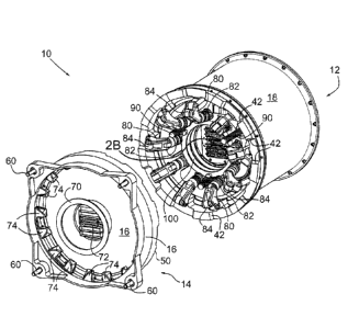
FIG. 1A is a perspective view of the mechanism 10 for releasably securing
a robotic system or arm to a spacecraft or payload comprised of an active
interface assembly 12 and a passive interface assembly 14 constructed in
accordance with the present disclosure.
6
Date Recue/Date Received 2021-01-18
CA 03106753 2021-01-18
WO 2021/000047
PCT/CA2020/050922
FIG. 1B shows a passive side connector alignment guide 260.
FIG. 2A is a perspective view of the mechanism 10 of FIG. 1, but taken
from a different perspective than shown in FIG. 1 showing the coupling
mechanism located in the active interface assembly used to rigidly couple the
active interface assembly 12 to the passive interface assembly 14 when in use.
FIG. 2B shows active side connector alignment guide 250.
FIG. 3 is a perspective view of the active interface assembly 12 inner
housing portion 100 and drive system used to mate the active interface
assembly 12 to the passive interface assembly 14 when in use.
1.0 FIG. 4A is an orthographic view of the compressible strut 82 which
forms
a connection between the inner housing 100 and each rocker arm 80.
FIG. 4B is a section view of the compressible strut 82.
FIG. 5 is an orthographic view of the active interface assembly 12
showing the equally spaced radial arrangement of latches, the spacing of
ballscrews and an example of the active side electrical connectors 118.
FIGS. 6A to 6F show selected operational stages involved in the mating
of the active interface assembly 12 to the passive interface assembly 12 when
in use, in which:
FIG. 6A shows the ready to latch stage once the active interface
assembly 12 has been maneuvered into position by the robotic arm and
sufficiently aligned with respect to the passive interface assembly 14 to
initiate
the action of the active interface assembly;
7
CA 03106753 2021-01-18
WO 2021/000047
PCT/CA2020/050922
FIG. 6B shows the contact stage (also termed capture stage) of the
active interface assembly 12 in contact with the passive interface assembly
14;
FIG. 6C shows the seated stage in which the active interface assembly
12 has been seated in the passive interface assembly 14;
FIG. 6D shows the maximum load position of the active interface
assembly 12 with respect to the passive interface assembly 14 during coupling;
FIG. 6E shows the relative position of the active interface assembly 12
with respect to the passive interface assembly 14 when the connectors of the
active and passive sides 118 and 72 are fully mated in it's self-locked
1.0 configuration; and
FIG. 6F shows the active interface assembly 12 fully mated with the
passive interface assembly 14.
FIG. 7 shows an arrangement for compliant mounting of the active side
connectors 118.
FIG. 8 depicts the operational scenario of robotic arm relocation.
FIG. 9 depicts the operational scenario of manipulation of a payload or
other object.
FIGS. 10, 11 and 12 are perspective views depicting a second, external
embodiment of the radial latch interface system, with FIGS. 13A through 13F
showing the external embodiment in key mechanism states.
FIGS. 14 and 15 depict a third, externally driven embodiment of the
radial latch interface system.
8
CA 03106753 2021-01-18
WO 2021/000047
PCT/CA2020/050922
FIGS. 16A and 16B showing said externally driven embodiment in the
ready to latch and fully mated conditions respectively.
DETAILED DESCRIPTION
Various embodiments and aspects of the disclosure will be described
with reference to details discussed below. The following description and
drawings are illustrative of the disclosure and are not to be construed as
limiting
the disclosure. The drawings are not necessarily to scale. Numerous specific
details are described to provide a thorough understanding of various
embodiments of the present disclosure. However, in certain instances, well-
known or conventional details are not described in order to provide a concise
discussion of embodiments of the present disclosure.
As used herein, the terms, "comprises" and "comprising" are to be
construed as being inclusive and open ended, and not exclusive. Specifically,
when used in this specification including claims, the terms, "comprises" and
"comprising" and variations thereof mean the specified features, steps or
components are included. These terms are not to be interpreted to exclude the
presence of other features, steps or components.
As used herein, the term "exemplary" means "serving as an example,
instance, or illustration," and should not be construed as preferred or
advantageous over other configurations disclosed herein.
As used herein, the terms "about" and "approximately", when used in
conjunction with ranges of dimensions of particles, compositions of mixtures
or
other physical properties or characteristics, are meant to cover slight
variations
9
CA 03106753 2021-01-18
WO 2021/000047
PCT/CA2020/050922
that may exist in the upper and lower limits of the ranges of dimensions so as
to
not exclude embodiments where on average most of the dimensions are
satisfied but where statistically dimensions may exist outside this region. It
is
not the intention to exclude embodiments such as these from the present
disclosure.
Embodiments of the active-passive interface system comprise the
following components in reference to the Figures.
Parts List
¨ both active and passive interface assemblies separated;
10 12 ¨ active interface assembly;
14¨ passive interface assembly;
16 ¨ passive interface housing;
18 ¨fixed outer active interface housing;
-- rotary actuator;
15 24 ¨ inner cable guide
40 ¨active face coupling interface flange
42 ¨ active coupling contact surface
50 ¨ passive face coupling interface flange
52 ¨ passive coupling contact surface
zo 60 ¨ passive interface mounting bolt, washer and thermal bushing
70 ¨ passive interface connector housing
72 ¨ passive side electrical connector
74 ¨ latch alignment guide
80 ¨ rocker arm
81 ¨ radial latch
82 ¨ compressible strut
84 ¨ latch roller
86 ¨ bushing
CA 03106753 2021-01-18
WO 2021/000047
PCT/CA2020/050922
88 ¨ latch roller pin
90 ¨ ballscrew
92 ¨ ballnut
94 ¨ locknut
96 ¨ bearing
100 ¨ mobile inner housing
102 ¨ drive gear
104 ¨ idler gear
110 ¨ outer cable guide
.. 114 ¨ outer cable guide flared opening
118 ¨ active side electrical connector
120 ¨ cable housing
122 ¨ cable cover
124 ¨ inner housing end stop
126 ¨ idler housing
128 ¨ idler shaft
130 ¨ link pivot pin
140¨ strut clevis
142¨ strut lug
.. 144 ¨ strut sleeve
146¨ spring
148 ¨ screw
150 ¨ washer
160 ¨ drive housing
162 ¨ drive plate
164 ¨ actuator adapter
166 ¨ actuator pinion
168 ¨ pinion spacer
170 ¨ needle bearing
172 ¨ thrust washer
11
CA 03106753 2021-01-18
WO 2021/000047
PCT/CA2020/050922
174 ¨ bearing retainer
176 ¨ bearing spacer
190 ¨ connector mounting plate
192¨ sleeve
194 ¨ spring
196 ¨ washer
198 ¨ washer
200 ¨ locknut
202 ¨ screw
210 ¨ bushing
212¨ rocker pivot pin
220 ¨ connecting pin
230 ¨mobile inner housing 100 axis
240 ¨fixed outer active interface housing 18 axis;
250 ¨ active side connector alignment feature
260 - passive side connector alignment feature
300 ¨ payload
500 ¨ robotic arm
510 ¨ spacecraft
520 ¨ earth
530 ¨ radio communication
610 ¨ both external active and passive interface assemblies;
612 ¨ external active interface assembly;
614 ¨ external passive interface assembly;
616 ¨ external passive interface housing;
618 ¨ external active interface housing;
620 ¨ mobile outer housing
622 ¨ drive ramp
624 ¨ drive roller
626 ¨ drive link
12
CA 03106753 2021-01-18
WO 2021/000047
PCT/CA2020/050922
628 ¨ kick ramp
630 ¨ kick roller
632 ¨ linear bearing
634 ¨ bolt driver
636 ¨ passive interface drive bolt
710 ¨ both externally driven active and passive interface assemblies;
712 ¨ externally driven active interface assembly;
714 ¨ externally driven passive interface assembly;
716 ¨ externally driven passive interface housing;
718 ¨ externally driven active interface housing;
720 ¨ driveshaft
722 ¨ worm
724 ¨ wheel
Structure
Passive Interface Assembly 14
Referring to FIGS. 1A and 2A, a passive interface assembly 14
comprises a passive interface housing 16 with multiple alignment guides 74,
multiple passive interface mounting bolts, washers and thermal bushings 60,
passive interface connector housing 70 and multiple passive side electrical
connectors 72. The passive interface housing 16 includes a passive face
coupling interface flange 50 having alternating raised sections 52 and lowered
sections arranged radially on the coupling face at equal intervals. The
inclined
faces between the raised sections 52 and lowered sections are the contacting
surfaces of the passive face coupling interface flange 50. Passive interface
mounting bolt, washer and thermal bushing 60 are mounted in four (4) housing
sections 58 forming part of passive interface housing 16. Passive interface
mounting bolt, washer and thermal bushing 60 are used to bolt passive
13
CA 03106753 2021-01-18
WO 2021/000047
PCT/CA2020/050922
interface assembly 14 to either a payload to be handled by the robotic arm or
a
surface intended to support the robotic arm as a base of operation, such as a
spacecraft deck. Passive interface connector housing 70 is mounted
concentrically within passive interface housing 16. Passive side electrical
connectors 72 are mounted within the passive interface connector housing.
Passive side electrical connectors 72 may include power, data and/or video
connectors, depending on the end use application of the interface assembly.
Alternatively, a custom arrangement of electrical contacts could be used
to optimize the use of the central volume and/or accommodate other devices
such as cameras, lights or other sensors. For passive interfaces that will be
used as a robotic arm base of operations the electrical contact arrangement is
suited solely to the needs of the robotic arm. For passive interfaces on
payloads the electrical contact arrangement may be suited to the needs of the
payload, for example to receive power and/or exchange data, notwithstanding
that the active side electrical connectors must be a common standardized
arrangement suitable to the needs of the robotic arm and all payloads to be
handled.
Visible in FIG. 2A are alignment guides 74 spaced around the periphery
of passive interface housing 16. An alignment guide 74 is required in each of
the spaces between radial latches 81 (to be discussed herein after) when
mated, so that the latch roller 84 and rocker arm 80 can interact with the
shaped guiding surfaces to continually reduce the lateral offset and roll
(angular) offset of the active and passive interface assemblies 12 and 14
respectively as the radial latches 81 move through their closing stroke.
Active Interface Assembly 12
14
CA 03106753 2021-01-18
WO 2021/000047
PCT/CA2020/050922
Referring to FIG. 1A and FIG. 2A, active interface assembly 12
comprises a fixed outer active interface housing 18, a translating
mobile inner housing 100, three or more radial latches 81 consisting comprised
of a rocker arm 80, a compressible link 82, a latch roller 84, bushing 86 and
latch roller pin 88 arranged in radial planes with pivoting connection to both
the
fixed outer active interface housing 18 and translating mobile inner housing
100, a rotary actuator 20 and mechanism to drive the translating motion, and
multiple active side electrical connectors 118 mounted to a connector plate
190
on compliant spring mounts.
Located at the distal end of fixed outer active interface housing 18 is an
active face coupling interface flange 40 having a series of alternating raised
and
lowered sections arranged radially on the coupling face at equal intervals.
The
inclined faces between the raised and lowered sections 42 are the contacting
surfaces of the active face coupling flange 40. At the proximal end of active
interface assembly 12, recessed within fixed outer active interface housing
18,
is drive plate 162 mounted normal to said longitudinal axis and supported by
drive housing 160. As such drive plate 162 and drive components supported
thereon are out of the primary structure load path for the robot arm and hence
immune to any effect that might be caused by external loads on the robot arm.
Drive plate 162 defines axes for the actuator 20, idler gears 104 and
drive gears 102 to which ballscrews 90 are mounted. While actuator 20 is
depicted coaxially with drive plate 162 alternative gear arrangements would
facilitate an off-center location, rendering the central space of drive plate
162
available for a large hole suitable for the passage of cable or for other
purposes
such as limit switches or other sensors.
CA 03106753 2021-01-18
WO 2021/000047
PCT/CA2020/050922
Three additional openings in drive plate 162 accommodate outer cable
guides 110 with flared openings 114. Inner cable guides 24 protrude through
the proximal end of outer cable guides 110 when the mobile inner housing 100
is fully retracted. Flared openings 114 in outer cable guides 110 ensure
cables,
being pulled into outer cable guides as inner housing 100 translates forward,
have a generously curved surface to guide them. Inner cable guides 24 nest
within outer cable guides 110 to provide a telescoping port for cable passage.
Motion of cables resulting from the translating motion of mobile inner housing
100 will be accommodated in the annulus between the actuator 20 and the
.. fixed outer active interface housing 18 after passing through inner and
outer
cable guides. The rotary actuator 20 includes a motor providing continuous
torque at high rotational speed coupled to a gear head (to reduce the speed
and increase the torque) and a sensor to control motor commutation and report
rotation of the drive axis.
FIG. 3 shows the components related to linear actuation. The assembly
of mobile inner housing 100, cable housing 120, cable cover 122, ballnuts 92
and inner cable guides 24 is translated along the mobile inner housing axis
230
when torque is delivered to the ballscrews 90 via actuator 20, actuator pinion
168 (see FIG. 6A), idler gears 104 and drive gears 102. Inner housing 100 is
fitted with link pivot pins 130 at the distal end. Each link pivot pin 130
provides
the attachment point for one end of a radial latch compressible strut 82.
Three
pads 124 on inner housing 100 come into contact with the mounting surface of
passive interface assembly 14 at end of travel.
More detail is visible in FIG. 6A wherein actuator 20 is mounted to drive
plate 162 via actuator adapter 164. Idler housing 126, when mounted to drive
16
CA 03106753 2021-01-18
WO 2021/000047
PCT/CA2020/050922
plate 162, constrains axial motion of actuator pinion 166 and idler gears 104
via
pinion spacer 168 and thrust washers 172, the latter placed one on each side
of
each idler gear. Thrust washers 172 and pinion spacer 168 may be adjusted at
assembly to achieve a loose running fit. Each idler gear 104 runs on a needle
bearing 170 which permits free rotation on idler shaft 128.
Each ballscrew 90 is fitted with a drive gear 102 and mounted to the
drive bracket 162 via bearings 96. Bearing spacers 176, which may be
adjusted at assembly, are placed on each side of the bearing set. Locknut 94
clamps drive gear 102, bearing spacers 176 and inner races of bearings 96
onto ballscrew 90, while bearing retainer 174 clamps outer races of bearings
96
to drive plate 162.
FIG. 4A shows compressible strut 82 in its extended state. FIG. 4B, a
cross section of compressible strut 82, shows screw 148 and washer 150
clamping sleeve 144 onto strut lug 142 while attaching strut clevis 140 to
strut
lug 142. Springs 146, shown in this embodiment nested in pairs which are
stacked in series, can be selected and configured to give the desired preload
at
the interface when fully mated.
FIG. 5 shows the distal end of the active interface assembly. Radial
latches, as noted above, each comprised of rocker arm 80, latch roller 84 and
compressible strut 82, are arranged in evenly spaced radial planes (9 in this
embodiment). Active side electrical connectors 118 are mounted to connector
plate 190.
FIG. 7 shows compliant mounting of connector plate 190 to cable
housing 120. The arrangement of sleeve 192, spring 194 and washer 196,
allows connector plate 190 to remain stationary during the final increment of
17
CA 03106753 2021-01-18
WO 2021/000047
PCT/CA2020/050922
forward motion of cable housing 120 via its attachment to mobile inner housing
100. Locknut 200, screw 202 and washer 198 ensure the sleeve remains
rigidly attached to connector plate 190. FIG. 7 shows one of three (3) or more
such spring/sleeve arrangements. Compliant mounting of the connectors
allows the mechanism end of stroke to be somewhat decoupled from the end of
stroke of connector mating, thus preventing the connectors from being
overloaded by the actuation force applied to mobile inner housing 100.
FIG. 8 shows the robotic arm 500, with a first active interface assembly
12 on its proximal end attached to a passive interface assembly 14 mounted on
spacecraft 510 and a second active interface assembly 12 on the manipulators
distal end positioned above a second passive interface assembly 14 on the
spacecraft 510. When the robotic arm 500 is operated from a ground station,
commands are relayed from earth 520 to the spacecraft 510 via radio
communication 530.
FIG. 9 shows the robotic arm 500, with a first active interface assembly
12 on its proximal end attached to passive interface assembly 14 mounted on
spacecraft 510 and a second active interface assembly 12 on the manipulators
distal end positioned a number of payloads 300, of which each has passive
interface assembly 14 mounted on them.
In operation as shown in FIGS. 8 and 9, the active interface assembly 12
mounted at the free end of the robotic arm 500 would be coarsely aligned with
the passive interface assembly 14 which in turn is secured at its proximal end
to
the object to be coupled to the robotic arm. Said object could be the
spacecraft
510 or payload 300. The active and passive interface assemblies 12 and 14
respectively are coarse aligned by the robotic arm 500 with respect to each
18
CA 03106753 2021-01-18
WO 2021/000047
PCT/CA2020/050922
other sufficiently to ensure they will meet "tooth" to "space" at their face
couplings in the correctly indexed position for the active side 118 and
passive
side 72 connectors to eventually engage. This coarse alignment is
accomplished via one or more of several means of manipulator control. A
human operator can teleoperate the motion of the free end of the robotic arm
500 towards the passive interface assembly 14 with the aid of a camera (not
shown) using either a target (not shown) mounted on or adjacent to the active
interface assembly 12. In another embodiment the manipulator motion can be
performed automatically where a computer vision system mounted on the
robotic arm aligns the interface assemblies through viewing one or more
landmarks mounted on one or both of the active and passive interface
assemblies. While the capture capability of the interface can be adjusted as
discussed above, the current embodiment with 3,200 Nm moment capacity and
340 mm outer diameter can close the interface with lateral offset of 2.5 cm,
roll
and wobble (angular) offsets of 2.8 degrees and combinations thereof to the
extent allowed before first contact occurs. This allows for closing of the
interface with residual errors commensurate with existing visual servoing
systems.
The operation of mating the active interface assembly to the passive
interface assembly will now be described with reference to FIGS. 6A to 6F.
Each of the FIGS. 6A to 6F illustrates a point of significance in the
operational
cycle and each point is a particular state in the mating process. Advancing
from one state to the next is achieved by energizing the rotary actuator 20
and
driving mobile inner housing 100 forward towards the passive interface
assembly 14 which in turn is mounted on a selected object. The actuator 20
19
CA 03106753 2021-01-18
WO 2021/000047
PCT/CA2020/050922
transmits torque through the actuator pinion 166, delivering torque to the
drive
gears 102 via the idler gears 104. The drive gears 102 are mounted to, and
deliver torque to the ballscrews 90. Each of the corresponding ballnuts 92 are
mounted to the mobile inner housing 100 such that they are prevented from
rotating. The three rotating ballscrews 90, working in unison, drive the inner
housing 100 forward. The action of the three rotating ballscrews 90, in
conjunction with the coplanar arrangement of link pivot pins 130 at the distal
end of mobile inner housing 100, ensure the inner housing axis 230 remains
aligned to the fixed outer active interface housing axis 240.
FIG. 6A shows the ready-to-latch state in which the mobile inner housing
100 is fully retracted. The latches (each comprised of rocker arm 80,
compressible strut 82 with springs 146 and latch rollers 84) are fully open,
allowing for the maximum permissible misalignment between active interface
assembly 12 and the passive interface assembly 14. For illustrative purposes,
the passive interface assembly 14 is shown fully aligned with the active
interface assembly 12, except for a separation of about 25 mm. The capture
envelope is also tolerant of lateral offset, roll and wobble (angular) offsets
although these are not shown in this illustration. FIG. 6B shows the contact
state in which the mobile inner housing 100 has advanced along axis 240
sufficient for the radial latch rollers to contact the inner rim of the
passive
interface. While this illustration shows all the latch rollers 84 contacting
simultaneously, this would more commonly occur sequentially when additional
initial coarse alignment errors are introduced. Regardless of the number of
latch rollers 84 in contact, and regardless of inner housing position when
contact first occurs, continued motion of the radial latches from this point
will
CA 03106753 2021-01-18
WO 2021/000047
PCT/CA2020/050922
force the seating of the interface. The roll alignment guides 74 on the
underside of the peripheral rim of the passive interface assembly 14 interact
with the radial latch rocker arms 80 and latch rollers 84 to achieve coarse
roll
and lateral alignment of active and passive interface assemblies 12 and 14
respectively. This ensures that the teeth of the active and passive face
coupling flanges 40 and 50 on active interface assembly 12 and passive
interface assembly 14 respectively engage correctly before fully seating. As
the
mechanism progresses through its closing stroke, latch rollers 84 collectively
form a continually expanding diameter interacting with both the peripheral rim
of
the passive face coupling interface flange 50 and alignment guides 74. When
the collective diameter of the latch rollers 84 exceeds the inner diameter of
the
peripheral rim, capture is complete.
FIG. 6C shows the seated state in which the mobile inner housing 100
has advanced sufficiently to force the face couplings 40 and 50 of the active
and passive interface assemblies 12 and 14 respectively into contact. Seating
of the active and passive face coupling flanges 40 and 50 respectively ensures
final alignment of the two active and passive interface assemblies 12 and
14. Continued motion of the mobile inner housing 100 will start to compress
the
springs 146 in each of the radial latch compressible struts 82, while the
alignment features of the active and passive side electrical connectors 250
and
260 respectively interact and engage. Compliant mounting of the connector
plate on the active side allows the active assembly electrical connectors 118
to
align to the passive assembly electrical connectors 72 independently of the
alignment of face couplings on active and passive sides.
21
CA 03106753 2021-01-18
WO 2021/000047
PCT/CA2020/050922
FIG. 6D shows the maximum interface load state. As the mobile inner
housing 100 continues forward the springs 146 of the compressible struts 82
achieve their maximum compression when the pivots at both ends of all the
compressible struts 82 become coplanar. The is the point of maximum preload
at the interface, and the point of minimum effort to drive the mobile inner
housing 100 forward due to the mechanical advantage afforded by the
geometry. From this point forward the latches become self-locking and the
interface cannot be forced open by external loads. Connector pins and sockets
in the electrical connectors 72 and 118 in the passive and active interfaces
begin to engage.
FIG. 6E shows the electrical connectors 72 and 118 in the mated state.
The electrical connectors 72 and 118 become fully mated just before the end of
the inner housing 100 stroke. As the mobile inner housing 100 continues
forward the springs 146 of the compressible struts or links 82 are relaxing
slightly.
FIG. 6F shows the fully mated state of the active and passive interface
assemblies 12 and 14 respectively. This state also represents the active and
passive interface assemblies 12 and 14 in a self-locked state. The interface
becomes fully mated at the end of the inner housing 100 stroke. At this point
three (3) pads 124 on the front face of the mobile inner housing 100 come into
contact with the surface to which the passive interface assembly 14 is
mounted. These three points of contact become the reaction point for the
radial
latches after the actuator is de-energized. As such, the system does not
require a brake. The springs 146 of the compressible links have relaxed to
their
final working length, establishing a fixed preload force applied by each
22
CA 03106753 2021-01-18
latch. Motion between the connectors mated position or state of FIG. 6E and
the fully mated position or state shown in FIG. 6F is accommodated by
compression of springs within the compliant mounts of the connector plate.
Driving the mobile inner housing 100 in the reverse direction will open
the interface using the same sequence of events but in reverse. This ensures
the electrical connectors 72 and 118 are fully disengaged prior to releasing
the
interface.
The present system is advantageous for several reasons. First, actuation
is via a single linear stroke which sequentially captures, aligns, seats and
latches the interface, mating electrical connectors in the final few
millimeters of
stroke. Once rotary actuator 20 is actuated, significant capture envelope and
self-alignment is achieved via multiple rotating latches. The interface
preload is
tuned through the appropriate selection of stiffness for spring 146 and evenly
distributed around the interface perimeter in a short and direct load path.
The
present system embodies a rich design space that includes design variations
for robotic base fixtures, tool fixtures and simple grasp fixtures as well as
very
large, externally driven, module to module interfaces.
Second, with the exception of the external radial latch embodiment
(described hereinafter), linear actuation uses a novel concept for guidance
that
does not employ linear carriages or sliding bushings. Linear motion is
achieved
by ensuring the proximal end of the mobile inner housing 100 is maintained
perpendicular to the axis of the end effector.
This orientation control, in conjunction with the coplanar arrangement of
pivot pins 130 in the mobile inner housing 100 (to which the compressible
struts
23
Date Recue/Date Received 2021-01-18
CA 03106753 2021-01-18
WO 2021/000047
PCT/CA2020/050922
82 are attached), ensures that the inner housing axis 230 remains aligned with
the end effector axis 240. Orientation control of mobile inner housing 100 is
achieved by driving said housing with multiple ball screws 90 driven from a
central rotary actuator 20. Avoiding the use of linear tracks and carriages
results in a design that is simple, light weight, with low part count and with
comparatively low requirements for precision.
Third the actuation load is highest shortly after the onset of strut
compression, thus occurring well before final latching of the interface.
Thereafter actuation load ramps down as struts approach the "on-center"
condition. Once past center, the actuation load approaches zero or may
actually go negative before the engagement of connectors. This ensures the
actuation torque required to release the interface is comparatively low
compared to the peak actuation torque. Low release torque is also desirable
for
implementation of an external EVA drive.
Fourth, at end of stroke the latches are in a self-locking state (externally
applied loads cannot force the latch open).
Fifth, the present system is scalable in several parameters. More
particularly, with respect to radius, the radius of contact is the fundamental
variable for moment capacity. The radii of inner pivots and outer pivots can
be
scaled together or individually. Scaling these three radii selectively allows
for a
tradeoff between interface capacity vs. capture envelope vs. volume for
connectors.
With respect to the number of latches, the quantity of latches can be
altered with three (3) being the minimum quantity. The spaces between latches
can accommodate other devices such as proximity sensors, force/moment
24
CA 03106753 2021-01-18
WO 2021/000047
PCT/CA2020/050922
sensors, cameras and lights where it is desired not to have these elements
mounted on the exterior of the active interface assembly 12. This is
particularly
advantageous when considering a smaller sized interface for a dexterous robot.
For example, at a load radius of 75 mm (i.e. 150 mm diameter "tool"
interface),
a 3 latch design could react 250 Nm overturning moment while allowing for
three inter-latch volumes sufficient to package force/moment sensing or
proximity sensing devices. Larger, robotic arm base interfaces (as shown in
the
current embodiment) require more latches to achieve both the high preload
required (as the preload of the interface is the sum of the individual
contributions of each latch), and the uniform distribution of load so
desirable in
such an application.
With respect to electrical connector capacity, the number and
arrangement of electrical contacts can be adjusted depending on end use, or in
the extreme case of a grasp-only interface the central space for connectors
can
be reduced to zero. In addition, a higher packing efficiency can be achieved
by
replacing OTS connectors with a custom arrangement of contact pins.
Sixth, with respect to interface preload, the selection, arrangement and
installation preload of springs 146 can be adjusted to tune interface preload,
thus allowing greater flexibility in the selection of the other,
aforementioned
scalable parameters.
In a first embodiment there is provided an interface coupling system for
releasably securing a selected object to a spacecraft and securing various
payloads to the selected object and to each other. The coupling system is
comprised of an active interface assembly and a passive interface assembly.
The active interface assembly includes 1) a flat coupling located at its
proximal
CA 03106753 2021-01-18
WO 2021/000047
PCT/CA2020/050922
end for structurally attaching it to the robotic arm, 2) electrical
connections for
electrically connecting it to the robotic arm, 3) a stepped interface coupling
located at its distal end 4) three or more latches arranged in radial planes
(radial latches), 5) each latch including a compressible strut sized to
produce a
predictable preload at the interface, 6) with each latch having a coupling to
an
inner housing that is driven forward (towards the passive side) in a single
continuous motion to achieve capture, alignment, seating, electrical
connection
and latching of the interface, and 7) electrical connectors and/or contacts
sufficient to support the needs of the robotic arm and the needs of future
payloads. The passive interface assembly includes 1) a first coupling located
at
its proximal end complementary to the second coupling on the active interface
assembly for structurally attaching the passive interface assembly to said
second coupling by clamping the rim of said first coupling to said second
coupling with said radial latches, 2) a second coupling located at its distal
end
for affixing the passive interface assembly to a desired object, 3) alignment
guides complementary to said radial latches, and 4) electrical connectors
and/or contacts sufficient to support the needs of the specific instance of
the
passive interface, be it a robotic arm base or payload handling point.
In an alternative embodiment an external radial latch interface system is
provided in which, the active interface assembly comprises an active interface
housing, a mobile outer housing, three (3) or more latches external to the
active
interface housing consisting of a rocker arm, a compressible link and a latch
roller arranged in radial planes with two pivoting connections to the active
interface housing, a linkage driven by the mobile outer housing, and an
actuator
and mechanism to drive the translating motion. In this external radial latch
26
CA 03106753 2021-01-18
WO 2021/000047
PCT/CA2020/050922
interface system the passive interface assembly includes an outward facing
coupling flange corresponding to the external arrangement of radial latches.
Said external radial latch embodiment, shown in FIGS. 10 and 11, is
ideally suited to smaller, dexterous robotic systems where moment capacity at
the interface is typically 300 Nm or less. This capacity is readily achievable
by
applying compressible struts of similar capacity and size as those of the
first
embodiment in said external arrangement of radial latches using a latch radius
of approximately 75 mm. Said external arrangement of radial latches renders
the central volume of said fixed inner housing available for the central
umbilical
connectors.
This external radial latch embodiment differs from the first embodiment in
requiring a drive linkage incorporating track rollers and ramps to force each
radial latch to close when the translating outer housing is moved in the
forward
direction and to open when moved in the rearward direction. This in turn
requires the use of precision linear guides to control the motion of said
translating outer housing with respect to said fixed inner housing.
Notwithstanding these differences, the core concept remains the same,
wherein a single actuation of three (3) or more latches 81 arranged in radial
planes sequentially captures, aligns, seats and latches the interface while
mating electrical connectors in the final portion of mechanism stroke.
FIGS. 10 and 11 depict an external embodiment of the radial latch
interface system 610. The active interface assembly 612 comprises a fixed
inner housing 618, a mobile outer housing 620, active side electrical
connectors
118 with connector alignment features 250, 4 external latches consisting of a
27
CA 03106753 2021-01-18
WO 2021/000047
PCT/CA2020/050922
rocker arm 80, a compressible link 82 and latch roller 84, arranged in radial
planes with two pivoting connections to the active inteface housing, and an
actuator 20 and mechanism to drive the translating motion via ballscrews 90.
The passive interface assembly 614 comprises a passive interface housing
616, passive side electrical connectors 72 with connector alignment features
260, and alignment guides 74. The active and passive interface assemblies
interface via coupling contact surfaces 42 and 52 on active and passive face
coupling flanges 40 and 50 respectively. Also evident in FIGS. 10 and 11 are
bolt driver 634 and passive interface drive bolt 636 which are typical
.. accessories of a dexterous robot interface, depicted here only to
demonstrate
feasibility.
FIG. 12 depicts the arrangement of track rollers and ramps required to
actuate the external arrangement of latches. For each latch, link pivot pin
130
forms a common centre for drive roller 624, drive link 626, compressible strut
clevis 140 and kick rollers 630 Drive roller 624 is guided by drive ramp 622
for
the portion of mechanism stroke from fully retracted until the on-centre
condition while kick rollers guided by kick ramps control the position of link
pivot
pin 130 for the portion of stroke from the on-centre condition until the fully
mated condition. This arrangement of rollers and ramps allows the mating of
electrical connectors to be completely separate from the mechanical latching
of
the interface.
FIGS. 13A through 13F depict the mechanism at key positions. The
drive linkage by which the mobile outer housing 620 actuates the radial
latches
81 is based on the pivoting connection of drive link 626 to active interface
housing 618 and the interaction of rollers and ramps depicted in FIG. 12.
28
CA 03106753 2021-01-18
WO 2021/000047
PCT/CA2020/050922
FIG. 13A shows the ready to latch state where the mechanism is fully
retracted, the latches fully open and where significant misalignments between
the active and passive interface assemblies may be present. As the
mechanism progresses through its stroke one or more latches will make contact
on or under the rim of the passive face coupling flange 50 as shown in FIG.
13B. Continued actuation closes the interface while the interaction of rocker
arms 80 and contact rollers 84 with alignment guides 74 guide the active and
passive interfaces into alignment and finally to a seated position as in FIG.
13C.
Further actuation compresses the springs 146 in each compressible strut 82.
The point of maximum load is shown in FIG.13D, also described as the on-
centre condition. Actuation beyond this point causes a small gap to form
between drive roller 624 and drive ramp 622 while kick rollers 630 come into
contact with kick ramps 628. Slight relaxation of springs 146 within each
compressible strut 82 has occurred between the on-centre position in FIG. 13D
and the over-centre condition of FIG. 13E, however continued actuation no
longer affects radial latches as kick rollers 630 and kick ramps 628 are
configured to hold the latch position stationary while the translating outer
housing 620 continues to drive active side electrical connectors 118 towards
engagement with passive side electrical connectors 72. FIG. 13E shows the
connectors beginning to engage while FIG. 13F shows the fully mated
condition.
In a third embodiment an externally actuated radial latch interface
system is provided in which the actuator is replaced with an external drive
shaft
in the form of a hexagonal bolt head, such as might be actuated by a dexterous
robot equipped with a bolt driver. This third embodiment uses internal radial
29
CA 03106753 2021-01-18
WO 2021/000047
PCT/CA2020/050922
latches similar to the first embodiment and is further modified to sacrifice
capture envelope in order to minimize mechanism stroke and overall length.
This configuration is suited to function as a separation plane mechanism, such
as might be employed to disconnect a portion of the robotic arm from itself to
facilitate repair or upgrade. This is particularly useful in a scenario where
there
are two robotic arms and they are also required to service each other. An
externally driven embodiment of the radial latch interface system 710 inserted
between the end of a boom and the cluster of joints to which it is connected
would facilitate either servicing of, or complete replacement of, the joint
cluster
with end effector. Similarly, additional placements either side of an elbow
joint
would facilitate the complete disassembly of the robotic arm into booms and
joint assemblies.
FIGS. 14 and 15 depict an externally driven embodiment of the radial
latch interface system 710. The active interface assembly 712 comprises a
fixed outer housing 718, a translating mobile inner housing 100, active side
electrical connectors 118 with connector alignment features 250, and 9
internal
latches consisting of a rocker arm 80, a compressible link 82 and latch roller
84,
arranged in radial planes with pivoting connection to both the fixed outer
housing and translating inner housing. An external embodiment of the passive
interface assembly 614 is mounted on the outside of the fixed outer housing
718 with its axis normal to the axis of the active interface assembly 712. A
passive interface drive bolt 636 is used to transfer rotary motion from an
external source, such as a dexterous robot bolt driver, via idler gears 104 to
a
driveshaft 720 which drives a worm 722 and wheel 724. Rotary motion is
further distributed to ballscrews 90 via drive gears 102.
CA 03106753 2021-01-18
The passive interface assembly 714 comprises a passive interface
housing 716, passive side electrical connectors 72 with connector alignment
features 260, and alignment guides 74. The active and passive interface
assemblies interface via coupling contact surfaces 42 and 52 on the active and
passive face coupling flanges 40 and 50 respectively.
FIG. 16A shows the ready to latch state where the mechanism is fully
retracted and the latches are fully open. Geometry of the rocker arms 80 has
been altered from the first embodiment in order to minimize mechanism stroke.
The capture envelope of active assembly 12 is correspondingly reduced,
however the insertion of the active interface assembly 712 into the passive
interface assembly 714 is performed by the dexterous robot on a known
trajectory, as compared to the scenario for the first embodiment wherein more
significant offsets can result from the approach controlled by visual
servoing. In
this case, a generous lead-in surface on the passive interface coupling 50 for
latch rollers 84 will be adequate to facilitate insertion.
FIG. 16B shows the fully mated condition where the mobile inner
housing 100 has travelled sufficiently to fully engage active side and passive
side electrical connectors 118 and 72 respectively, and to drive the
compressible strut 82 to an over-center condition. The mechanism is self-
locking in this condition, the external tool drive can be removed and the
interface will remain closed despite any amount of externally applied load.
In the above mentioned embodiments further comprising a sensor
system mounted on one or both of the active and passive interface assemblies
for enabling remote operator control of all activities associated with
aligning and
31
Date Recue/Date Received 2021-01-18
CA 03106753 2021-01-18
WO 2021/000047
PCT/CA2020/050922
latching the active and passive interface assemblies together based on
feedback from the sensor system. This sensor system comprises any one or
combination of a camera based vision system, proximity sensors, radar and
LIDAR.
10
32