Note: Descriptions are shown in the official language in which they were submitted.
CA 03106874 2021-01-19
WO 2020/020604 PCT/EP2019/068104
- 1 -
AEROSOL GENERATING ARTICLES
Technical Field
The present disclosure relates generally to aerosol generating articles, and
more
particularly to an aerosol generating article for use with an aerosol
generating device
for heating the aerosol generating article to generate an aerosol for
inhalation by a user.
Technical Background
Devices which heat, rather than burn, an aerosol generating material to
produce an
aerosol for inhalation have become popular with consumers in recent years.
Such devices can use one of a number of different approaches to provide heat
to the
aerosol generating material. One such approach is to provide an aerosol
generating
device which employs an induction heating system and into which an aerosol
generating article, comprising aerosol generating material, can be removably
inserted
by a user. In such a device, an induction coil is provided with the device and
an
inductively heatable susceptor is provided typically with the aerosol
generating article.
Electrical energy is supplied to the induction coil when a user activates the
device which
in turn generates an alternating electromagnetic field. The susceptor couples
with the
electromagnetic field and generates heat which is transferred, for example by
conduction, to the aerosol generating material and a vapour or aerosol is
generated as
the aerosol generating material is heated.
The characteristics of the aerosol generated by the aerosol generating device
are
dependent upon a number of factors, including the construction of the aerosol
generating article used with the aerosol generating device. There is,
therefore, a desire
to provide an aerosol generating article which enables the characteristics of
the aerosol
generated during use of the article to be improved.
CA 03106874 2021-01-19
WO 2020/020604 PCT/EP2019/068104
- 2 -
Summary of the Disclosure
According to a first aspect of the present disclosure, there is provided an
aerosol
generating article comprising:
a substantially cylindrical cup containing a plant-based aerosol generating
material and at least one inductively heatable susceptor element, wherein the
cup
comprises an open end and a bottom wall;
the cup having a self-supporting moulded form and including a flange at the
open end and a closure attached to the flange;
wherein the closure and/or bottom wall is porous or comprises one or more
openings.
The aerosol generating article is for use with an aerosol generating device
for heating
the plant-based aerosol generating material, without burning the aerosol
generating
material, to volatise at least one component of the plant-based aerosol
generating
material and thereby generate a vapour which cools and condenses to form an
aerosol
for inhalation by a user of the aerosol generating device.
In general terms, a vapour is a substance in the gas phase at a temperature
lower than
its critical temperature, which means that the vapour can be condensed to a
liquid by
.. increasing its pressure without reducing the temperature, whereas an
aerosol is a
suspension of fine solid particles or liquid droplets, in air or another gas.
It should,
however, be noted that the terms 'aerosol' and 'vapour' may be used
interchangeably
in this specification, particularly with regard to the form of the inhalable
medium that
is generated for inhalation by a user.
The use of at least one inductively heatable susceptor element provides a
convenient,
effective and energy efficient way to heat the plant-based aerosol generating
material.
When the aerosol generating article is positioned in an aerosol generating
device and
exposed to an alternating electromagnetic field, heat is generated in the
inductively
heatable susceptor element due to eddy currents and magnetic hysteresis losses
resulting in a conversion of energy from electromagnetic to heat. The heat
generated in
the inductively heatable susceptor element is transferred to the plant-based
aerosol
CA 03106874 2021-01-19
WO 2020/020604 PCT/EP2019/068104
- 3 -
generating material whereupon it is heated to generate a vapour which cools
and
condenses to form an aerosol with the desired characteristics.
The cup may include a substantially cylindrical side wall. The bottom wall may
be
substantially circular. The closure may be substantially circular. The
cylindrical form
of the resulting aerosol generating article with its substantially circular
cross-section
may facilitate packaging of multiple aerosol generating articles and/or may
facilitate
insertion of the aerosol generating article into a correspondingly shaped
heating
compartment of an aerosol generating device.
The flange may extend outwardly away from the side wall, for example in a
radially
outward direction. Thus, the flange does not extend across the open end of the
cup,
thereby facilitating the flow of fluid (e.g. air and/or vapour and/or aerosol)
through the
cup during use of the aerosol generating article with an aerosol generating
device. In
embodiments in which the side wall is substantially cylindrical, the flange
may
comprise a substantially circular lip.
The bottom wall may comprise a plurality of openings. In other words, the
bottom wall
may be perforated. The openings may be substantially circular and may have a
diameter
between 0.5 mm and 5 mm, preferably between 1.0 mm and 2.5 mm. In some
embodiments, the bottom wall may comprise a first opening which may have a
diameter
between 1.2 mm and 2.5 mm and a plurality of second openings which may be
positioned around the central opening. The first opening may be configured for
the
insertion of a temperature sensor when the aerosol generating article is
positioned in an
aerosol generating device. The first opening may be a central opening and the
second
openings may be peripheral openings. The first opening may also be omitted.
The
bottom wall may comprise between 5 and 10 of said second or peripheral
openings. The
second or peripheral openings may be substantially circular and may have a
diameter
between 0.5 mm and 1 mm. The second openings are typically smaller than the
first
opening.
CA 03106874 2021-01-19
WO 2020/020604 PCT/EP2019/068104
- 4 -
The openings intended to form air and/or flavour flow passages, i.e., the
second
openings, are preferably sized to be smaller than the particle size (D90) of
the plant-
based aerosol generating material. As a result, no significant loss of
material is observed
through the bottom wall of the cup. The particle size in volume (D90) is
determined by
dry dispersion of the sample and laser refractometry using the Malvern
Mastersizer
3000.
The bottom wall may comprise a material which is porous to allow air to flow
through
the bottom wall. The bottom wall may comprise a material which is air-
resistant, for
example a material having a non-porous wall structure, but which is perforated
to allow
air to flow through controlled-size openings. The bottom wall can include one
or more
of said openings. Preferably, the cup body including the side wall and bottom
wall
comprises a material which is air-resistant. The flange may also comprise such
a
material. The openings are needed to allow air to flow through the bottom
wall. The
air-permeable bottom wall promotes air flow through the aerosol generating
article
thereby optimising aerosol generation and transfer to the user, for example
via a
mouthpiece of an aerosol generating device.
The closure may comprise a material which is porous and/or comprises openings
to
allow air and vapour to flow through the closure. The closure may comprise a
porous
material selected from the group consisting of porous paper, non-woven fabric,
a
polymer sheet, and combinations thereof. The closure may include one or more
perforations. The closure may comprise a material which is itself resistant to
air such
that the openings or perforations are needed to allow air (and other fluids
including
vapour and aerosol) to flow through the closure. In addition to retaining the
plant-based
aerosol generating material in the cup, the air-permeable closure
advantageously
promotes air flow through the aerosol generating article thereby optimising
aerosol
generation and transfer to the user, for example via a mouthpiece of an
aerosol
generating device. The closure may comprise the same material as the bottom
wall.
By "air-resistant" is meant a material that is not necessarily a barrier to
oxygen during
storage but a material that at least does not allow the flow of air and vapour
during use.
CA 03106874 2021-01-19
WO 2020/020604 PCT/EP2019/068104
- 5 -
The cup may comprise one or more of paper, cellulose fibres and binder,
cotton, silk,
polysaccharide polymer, starch, or compostable polyester (according to
EN13432).
These materials may be made air-resistant such as by their composition or by
surface
coating or lamination and made permeable by perforations or openings. The cup
is
cheap and easy to manufacture and is safe for use even at high temperatures.
The self-
supporting moulded form of the cup enables the cup to retain its shape and
facilitates
handling of the aerosol generating article, for example during manufacture
and/or by a
user.
The cup and/or closure may further contain tobacco and/or flavour. The tobacco
and/or
flavour may improve or mask the taste of the packaging ingredients, e.g.
paper, to give
a more pleasant taste. The flavour may be tobacco, fruit, plant, nut, flower
and so on.
The tobacco and/or flavour may be contained as an ingredient of the paper. The
tobacco
may be embedded in the paper or applied thereon such as by coating or
layering. The
tobacco may be in the form particles, flakes, leaf fragments, strip(s),
layer(s) and
combinations thereof.
The aerosol generating article may comprise at least two, and preferably three
or more,
substantially planar inductively heatable susceptor elements which may be
spaced from
each other in an axial direction of the cup, i.e. along a cup axis extending
between the
bottom wall and the open end. The at least two substantially planar
inductively heatable
susceptor elements may be spaced from the bottom wall and the closure at the
open end
of the cup. With such an arrangement, a maximum transfer of heat from the
inductively
heatable susceptor elements to the plant-based aerosol generating material is
achieved
during use of the aerosol generating article with an aerosol generating
device.
In some embodiments, at least part, and preferably all, of the inductively
heatable
susceptor elements are planar and preferably annular in a radial direction of
the cup.
This allows a plurality of inductively heatable susceptor elements to be
positioned in
the cup.
CA 03106874 2021-01-19
WO 2020/020604 PCT/EP2019/068104
- 6 -
The inductively heatable susceptor elements may be spaced from each other by a
uniform distance. The uniform spacing between the inductively heatable
susceptor
elements ensures that the plant-based aerosol generating material is heated
uniformly
during use of the aerosol generating article with an aerosol generating
device.
A layer of plant-based aerosol generating material may be positioned between
adjacent
inductively heatable susceptor elements. Positioning a layer of the plant-
based aerosol
generating material between adjacent inductively heatable susceptor elements
ensures
that a maximum amount of heat is transferred to the aerosol generating
material from
the inductively heatable susceptor elements during use of the aerosol
generating article
with an aerosol generating device. This in turn ensures that a sufficient
amount of
aerosol is generated.
The plant-based aerosol generating material may be any type of solid or semi-
solid
material. For example, the plant-based aerosol generating material typically
contains a
mixture of powdered or crumbed material. Other example types of aerosol
generating
solids may include granules, pellets, shreds, strands, particles, gel, strips,
loose leaves,
cut leaves, cut filler, porous material, foam material or sheets. The plant-
based aerosol
generating material may comprise tobacco. It may advantageously comprise
reconstituted tobacco.
The foam material may comprise a plurality of fine particles (e.g. tobacco
particles).
The tobacco particles may have a particle size (D90) between 50 and 180 gm,
preferably between 60 and 140 gm, further preferably between 65 and 125 gm,
even
further preferably between 70 and 110 gm, particularly preferably between 75
and 90
gm, e.g. having a particle size (D90) of about 80 gm. The foam material may
further
comprise an aerosol forming agent such as propylene glycol, glycerol or a
combination
thereof. The aerosol forming agent can further comprise water. According to
certain
embodiments, no water is contained, though, since water in aerosol form can
burn the
mouth of a user. Water can be contained in an amount of 0 to 15 wt.% of the
weight of
the foam material, e.g. 5 to 10 wt.%. The foam material may further comprise a
solvent
and/or an acid and/or an ester in an amount of up to 15 wt.%, based on the
total weight
CA 03106874 2021-01-19
WO 2020/020604 PCT/EP2019/068104
- 7 -
of the foam material, preferably up to 5 wt.%. The foam material may further
comprise
a foam forming agent. The foam forming agent may be non-protein containing
polysaccharide. The foam forming agent may be selected from the group
consisting of
agar, gellan gum, lecithin, polyglycerol esters of fatty acids, glycerol
esters of fatty
acids, sorbitan esters of fatty acids, and/or mixtures thereof, without being
limited
thereto. A preferred foam forming agent is gellan gum. The foam material may
comprise a foam stabilizing agent. The foam stabilizing agent may comprise
cellulose
gum, hydroxyalkylated carbohydrates, derivatives thereof, e.g. salts thereof,
preferably
alkali metal salts thereof, e.g. sodium and/or potassium salts thereof, and
mixtures
thereof. Both of the cellulose gum and the hydroxyalkylated carbohydrates are
not
particularly restricted. According to certain, preferred, embodiments, the
foam
stabilizing agent is a cellulose gum, particularly a carboxymethylcellulose,
or a
derivative thereof. An exemplary, preferred, cellulose gum which may be used
in the
present invention is CEKOLO 2000 and/or Ceroga 4550C (C.E. Roeper GmbH), a
purified sodium carboxymethylcellulose each. Another class of suitable foam
stabilizing agents are hydroxyalkylated carbohydrates, and more preferably
cellulose
ethers and derivatives thereof A cellulose ether or derivative thereof that
can be used
can have at least one substituent selected from the group consisting of
methyl, ethyl,
hydroxyethyl and hydroxypropyl groups. It can further be substituted with a
linear or
branched substituted or unsubstituted alkyl radicals having 1 to 20 carbon
atoms or an
aralkyl radical having 7 to 20 carbon atoms. Such radical is preferably
attached by an
ether linkage. Suitable substituents can include e.g. a hydroxy group, a
carboxy group
with 1 to 4 carbon atoms, etc. According to certain embodiments the cellulose
ether is
selected from hydroxyethylcellulose, methylcellulose,
methylhydroxyethylcellulose, a
volume of water and/or a moisture additive, such as a humectant. The foam
material
may be porous, which is open pored and may allow a flow of air and/or vapour
through
the foam material. The foam material may have an aeration of at least 4 vol.%,
preferably having an aeration of at least 5 vol.%, e.g. 5 to 7 vol.%, based on
the total
volume of the foam material. In a first example, the foam material contains 16
wt.% of
tobacco powder, 28 wt.% of propylene glycol (PG), 42 wt.% of glycerine (G), 2
wt.%
of purified water, 4 wt.% of gellan gum, 8 wt.% of Ceroga 4550C. In a second
example,
CA 03106874 2021-01-19
WO 2020/020604 PCT/EP2019/068104
- 8 -
the foam material contains 33 wt.% tobacco powder, 16 wt.% propylene glycol,
24
wt.% glycerine, 4 wt.% purified water, 7 wt.% gellan gum and 16 wt.% Ceroga
4550.
The plant-based aerosol generating material may comprise tobacco material and
an
aerosol former in a ratio by weight comprised between 0.2:1 and 4:1,
preferably
between 0.52:1 and 2:1. The aerosol former, which acts as a humectant, may
include
polyhydric alcohols and mixtures thereof such as glycerine or propylene
glycol.
Typically, the plant-based aerosol generating material may comprise an aerosol-
former
content of between approximately 5% and approximately 50% on a dry weight
basis.
Upon heating, the plant-based aerosol generating material may release volatile
compounds. The volatile compounds may include nicotine or flavour compounds
such
as tobacco flavouring.
The plant-based aerosol generating material may have a particle size, for
example a
sieved particle size, less than 2 mm, preferably less than 1.7 mm. The density
of the
plant-based aerosol generating material in the cup may be between 300 g/1 and
450 g/l,
preferably between 350 g/1 and 400 g/l, most preferably about 380 g/l. With
this
arrangement, an aerosol with good characteristics may be generated during use
of the
.. aerosol generating article with an aerosol generating device. Preferably,
the aerosol
generating article contains about 150 to 250 mg, preferably about 200 mg of
plant-
based aerosol generating material.
The or each inductively heatable susceptor element may comprise one or more,
but not
limited, of aluminium, iron, nickel, stainless steel and alloys thereof, e.g.
Nickel
Chromium or Nickel Copper.
The or each inductively heatable susceptor element may comprise a disc or a
ring-
shaped susceptor element. The use of a ring-shaped susceptor element is
advantageous
because the central opening in the susceptor element facilitates the flow of
fluid (i.e. air
and/or vapour and/or aerosol) through the aerosol generating article during
use of the
aerosol generating article with an aerosol generating device.
CA 03106874 2021-01-19
WO 2020/020604 PCT/EP2019/068104
- 9 -
The or each ring-shaped susceptor element may have an external diameter
between 6
mm and 10 mm, preferably about 8 mm, an inner diameter between 1 mm and 5 mm,
preferably 3 about mm, and a thickness between 30 gm and 100 gm, preferably
about
50 gm.
The cup may have a wall thickness between 0.3 mm and 1 mm, preferably between
0.4
mm and 0.6 mm, most preferably about 0.5 mm.
The cup may have a substantially cylindrical inner cavity. The use of a
cylindrical inner
cavity is particularly suited to accommodating disc-shaped or ring-shaped
susceptor
elements.
The cup may have a height between 9 mm and 10 mm, a body diameter between 10
mm and 11 mm, and a flange diameter between 13 mm and 15 mm.
The cup may comprise one or more positioning members configured for
positioning the
or each inductively heatable susceptor element at a predetermined distance
from the
bottom wall and from the open end of the cup and/or for positioning a
plurality of
inductively heatable susceptor elements at predetermined distances from each
other.
The inductively heatable susceptor element(s) can be easily and reliably
positioned in
the cup in a predetermined position with respect to the aerosol generating
material,
thereby ensuring that uniform heating of the aerosol generating material can
be
achieved. The use of a positioning member can also help to ensure that the
inductively
.. heatable susceptor element is correctly positioned for coupling with an
electromagnetic
field during use of the aerosol generating article with an aerosol generating
device,
thereby ensuring that maximum heat generation is achieved in the inductively
heatable
susceptor element.
.. The positioning member may comprise a retaining surface which may extend
continuously in a circumferential direction of an inside wall of the cup. With
this
arrangement, the inductively heatable susceptor element is reliably supported
around
CA 03106874 2021-01-19
WO 2020/020604 PCT/EP2019/068104
- 10 -
its periphery. The positioning member may comprise at least two, preferably
three or
more, separate retaining surfaces at circumferentially spaced locations inside
the cup.
With this arrangement, the periphery of the inductively heatable susceptor
element is
supported at discrete circumferential positions, thereby increasing the
contact area
between the aerosol generating material and the inductively heatable susceptor
element
around its periphery and maximising the amount of heat transfer to the aerosol
generating material.
The or each positioning member may comprise a circumferential step or a
plurality of
circumferentially discontinuous radial segments or a plurality of
circumferentially
discontinuous radial segments affixed to or being integral to the cup.
Reliable
positioning of the inductively heatable susceptor element(s) in the cup is
assured by the
positioning member(s).
The cup may include a cup axis extending between the open end and the bottom
wall
and at least two of said positioning members at different locations along the
cup axis.
The positioning member located along the cup axis nearest to the open end may
be
closer to an inside wall of the cup than the other positioning member(s). The
positioning
members ensure that a uniform distribution of the inductively heatable
susceptor
elements throughout the plant-based aerosol generating material can be
achieved and
this in turn ensures a uniform transfer of heat from the inductively heatable
susceptor
elements to the plant-based aerosol generating material during use of the
aerosol
generating article with an aerosol generating device.
The cup may further comprise a stopper extending from the side wall in a
radially
inward direction. The stopper facilitates reliable and accurate positioning of
the
inductively heatable susceptor element in the cup in a direction orthogonal to
the cup
axis, for example in the radial direction.
The circumferential step or each of said discontinuous radial segments may
include the
stopper and the positioning member. This provides a simple and robust
structure.
CA 03106874 2021-01-19
WO 2020/020604 PCT/EP2019/068104
- 11 -
In one aspect, the closure may be attached to the flange by a snap-fit
connection.
Alternatively or in addition, the closure may be adhered to the flange. For
example, the
closure may be glued or welded to the flange. The closure is thereby securely
and
reliably attached to the flange, ensuring that the aerosol generating material
and the
inductively heatable susceptor element(s) are retained in the cup.
The snap-fit connection may include a continuously extending circumferential
hook at
the peripheral edge of the closure which cooperates with the flange. The snap-
fit
connection may alternatively include a plurality of circumferentially spaced
hook
members at the peripheral edge of the closure which cooperate with the flange.
In an
alternative, the snap-fit connection may include a continuously extending
circumferential hook at the peripheral edge of the cup, e.g. at the flange,
which
cooperates with the closure. The snap-fit connection may alternatively include
a
plurality of circumferentially spaced hook members at the peripheral edge of
the cup
e.g. at the flange, which cooperate with the closure.
The flange may comprise upper and lower flange portions which may project
inwardly
across the open end of the cup and which may define a recess therebetween. The
periphery of the closure may be locatable in the recess to provide the snap-
fit
connection. The upper and lower flange portions may be continuous
circumferential
flange portions and the recess may be a continuous circumferential recess in
which the
periphery of the closure may be locatable to provide the snap-fit connection.
Brief Description of the Drawings
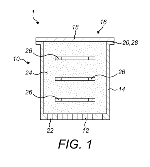
Figure 1 is diagrammatic cross-sectional side view of an aerosol generating
article
comprising a first example of a cup containing a plant-based aerosol
generating material
and a plurality of ring-shaped inductively heatable susceptor elements;
Figure 2 is a plan view of one of the ring-shaped inductively heatable
susceptor
elements;
Figure 3a is a plan view of a second example of a cup;
Figure 3b is a cross-sectional view along the line A-A in Figure 3a;
Figure 3c is a side view of the cup of Figures 3a and 3b;
CA 03106874 2021-01-19
WO 2020/020604 PCT/EP2019/068104
- 12 -
Figure 3d is a perspective view of the cup of Figures 3a to 3c;
Figures 4a and 4b are diagrammatic cross-sectional side views of an aerosol
generating
article similar to that shown in Figure 1, showing a first example of a snap-
fit
connection between the cup and a closure;
Figure 5a is a diagrammatic perspective view of an alternative closure for use
with first
example of the snap-fit connection of Figures 4a and 4b;
Figures 5b and 5c are respectively views from opposite sides of the closure of
Figure
5 a;
Figure 6a is a diagrammatic perspective view of another alternative closure
for use with
first example of the snap-fit connection of Figures 4a and 4b;
Figures 6b and 6c are respectively views from opposite sides of the closure of
Figure
6a;
Figures 7a and 7b are diagrammatic cross-sectional side views of an aerosol
generating
article similar to that shown in Figure 1, showing a second example of a snap-
fit
connection between the cup and a closure;
Figures 8a and 8b are respectively a diagrammatic cross-sectional side view
and a
diagrammatic plan view of a cup including positioning members which extend
continuously around the inner surface of a side wall of the cup;
Figure 8c is a diagrammatic cross-sectional side view of an aerosol generating
article
comprising the cup of Figures 8a and 8b;
Figure 9a is a diagrammatic plan view of a cup including positioning members
at
discrete circumferential locations around the inner surface of the side wall
of the cup;
and
Figures 9b and 9c are diagrammatic cross-sectional views respectively along
the lines
A-A and B-B in Figure 9a after filling the cup with plant-based aerosol
generating
material and inductively heatable susceptor elements.
Detailed Description of Embodiments
Embodiments of the present disclosure will now be described by way of example
only
and with reference to the accompanying drawings.
CA 03106874 2021-01-19
WO 2020/020604 PCT/EP2019/068104
- 13 -
Referring initially to Figures 1 and 2, there is shown a first example of an
aerosol
generating article 1 for use with an aerosol generating device comprising an
electromagnetic field generator (e.g. an induction heating system comprising
an
induction coil). The aerosol generating article 1 comprises a first example of
a
cylindrical cup 10 having a substantially circular bottom wall 12, a
substantially
cylindrical side wall 14 and a substantially circular open end 16 sealed by a
substantially circular closure 18 affixed to a flange 20 at the open end 16 of
the cup 10.
The cylindrical cup 10 is typically a paper cup, for example a moulded paper
cup having
a self-supporting moulded form. The bottom wall 12 is air-permeable and in the
illustrated embodiment includes a plurality of openings or perforations 22. In
some
embodiments, the paper (or other material) from which the cup 10 is
manufactured may
have a porous structure which allows air to flow through the bottom wall 12
without
the need for the openings or perforations 22.
The cup 10 contains a plant-based aerosol generating material 24, for example
a solid
or semi-solid material which can have a powdered or crumbed form with a sieved
particle size less than 1.7 mm. The plant-based aerosol generating material 24
also
comprises an aerosol-former, such as glycerine or propylene glycol, which acts
as a
humectant. Typically, the plant-based aerosol generating material 24 may
comprise an
aerosol-former content of between approximately 30% and approximately 50% on a
dry weight basis, and possibly approximately 40% on a dry weight basis. Upon
being
heated, the plant-based aerosol generating material 24 releases volatile
compounds
possibly including nicotine or flavour compounds such as tobacco flavouring.
The cup 10 also contains a plurality of ring-shaped inductively heatable
susceptor
elements 26. The inductively heatable susceptor elements 26 are arranged
coaxially
inside the cylindrical cup 10 with respect to a cup axis extending between the
bottom
wall 12 and the open end 16 and are spaced apart in the axial direction along
the cup
axis. When an alternating electromagnetic field is applied in the vicinity of
the
inductively heatable susceptor elements 26 during use of the article 1 in an
aerosol
generating device, heat is generated in the inductively heatable susceptor
elements 26
CA 03106874 2021-01-19
WO 2020/020604 PCT/EP2019/068104
- 14 -
due to eddy currents and magnetic hysteresis losses and the heat is
transferred from the
inductively heatable susceptor elements 26 to the plant-based aerosol
generating
material 24 to heat the plant-based aerosol generating material 24 without
burning it
and to thereby generate a vapour which cools and condenses to form an aerosol
for
inhalation by a user. The inductively heatable susceptor elements 26 are in
contact over
substantially their entire surfaces with the plant-based aerosol generating
material 24,
thus enabling heat to be transferred directly, and therefore efficiently, from
the
inductively heatable susceptor elements 26 to the plant-based aerosol
generating
material 24.
The closure 18 at the open end 16 retains the plant-based aerosol generating
material
24 and the inductively heatable susceptor elements 26 inside the cup 10. It
will be
understood by one of ordinary skill in the art that the closure 18 needs to be
air-
permeable so that a vapour or aerosol generated due to heating of the plant-
based
aerosol generating material 24 can flow out of the cylindrical cup 10 during
use of the
aerosol generating article 1 in an aerosol generating device. In the example
illustrated
in Figure 1, closure 18 comprises a porous material through which air and
vapour can
flow. The flange 20 comprises an outwardly extending circular lip 28 and the
closure
18 is affixed to the circular lip 28 by an adhesive or by welding, for example
using an
ultrasonic welding technique or a hot press.
Referring now to Figures 3a to 3d, there is shown a second example of a
cylindrical cup
110 which is similar to the cup 10 described above with reference to Figure 1
and in
which corresponding elements are designated using the same reference numerals.
As best seen in Figures 3a and 3b, the bottom wall 12 comprises a first
opening in the
form of a central opening 32 and a plurality of second openings in the form of
circumferentially spaced peripheral openings 30 which are positioned around
the
central opening 32. The peripheral openings 30 are substantially circular and
have a
diameter typically between 0.5 mm and 1 mm. The central opening 32 is also
substantially circular and has a larger diameter than the peripheral openings
30,
typically between 1.2 mm and 2.5 mm.
CA 03106874 2021-01-19
WO 2020/020604 PCT/EP2019/068104
- 15 -
Referring now to Figures 4a and 4b, there is shown a second example of an
aerosol
generating article 2 which is similar to the aerosol generating article 1
described above
with reference to Figures 1 and 2 and in which corresponding elements are
designated
using the same reference numerals. It will be noted that the plant-based
aerosol
generating material 24 and the inductively heatable susceptor elements 26 are
not
shown in Figures 4a and 4b.
The aerosol generating article 2 comprises a closure 18 having a snap-fit
connection
34. The snap-fit connection 34 comprises a circumferentially extending hook 36
forming a continuously extending circumferential recess 38 in which the flange
20 can
be securely located as shown in Figure 4b. The hook 36 includes a tapered
surface 40
which allows it to slide past the flange 20 when the closure 18 is moved in
the direction
of the cup axis from the position shown in Figure 4a to the position shown in
Figure
4b. It will be understood by one of ordinary skill in the art that the side
wall 14 of the
cup 10 proximate the open end 16 and/or the hook 36 may flex as the closure 18
is
pressed onto the flange 20 before one or both components return to their
original
positions, to thereby allow the flange 20 to be accommodated and securely
retained in
the circumferential recess 38 as shown in Figure 4b.
Figures 5a to Sc illustrate an alternative closure 18 having a snap-fit
connection 34
which can be used with the cup 10 described above. The snap-fit connection 34
comprises a plurality of circumferentially-spaced hook members 90 which extend
downwardly from a lower surface 92 of the closure 18 so that the peripheral
edge 94 of
the closure 18 has a smooth edge contour when the closure 18 is viewed from
the top
(see Figure 5b). Each hook member 90 forms a recess in which the flange 20 can
be
located in the same manner as described above with reference to Figure 4b. The
hook
members 90 individually flex as the closure 18 is pressed onto the flange 20
before the
hook members 90 return to their original positions, to thereby allow the
flange 20 to be
accommodated and securely retained in the recesses.
CA 03106874 2021-01-19
WO 2020/020604 PCT/EP2019/068104
- 16 -
Figures 6a to 6c illustrate an alternative closure 18 having a snap-fit
connection 34
which can be used with the cup 10 described above. The snap-fit connection 34
comprises a plurality of circumferentially-spaced hook members 90 which extend
downwardly from the peripheral edge 94 of the closure 18 to provide a
crenelated edge
contour when the closure 18 is viewed from the top (see Figure 6b). Each hook
member
90 forms a recess in which the flange 20 can be located in the same manner as
described
above with reference to Figure 4b. The hook members 90 individually flex as
the
closure 18 is pressed onto the flange 20 before the hook members 90 return to
their
original positions, to thereby allow the flange 20 to be accommodated and
securely
retained in the recesses.
It will be noted that the closures 18 illustrated in Figures 5 and 6 comprise
a plurality
of circumferentially arranged openings 98 which allow air and vapour to flow
through
the closure 18. The openings 98 could, however, be omitted if the closure 18
has a
sufficiently porous structure to allow air and vapour to flow therethrough.
Referring now to Figures 7a and 7b, there is shown a third example of an
aerosol
generating article 3 which is similar to the aerosol generating articles 1, 2
described
above and in which corresponding elements are designated using the same
reference
numerals. It will again be noted that the plant-based aerosol generating
material 24 and
the inductively heatable susceptor elements 26 are not shown in Figures 7a and
7b.
The aerosol generating article 3 comprises a cup 210 having a flange 20 which
projects
in the radially inward direction and forms a snap-fit connection 42. In more
detail, the
snap-fit connection 42 comprises a continuously extending upper
circumferential
flange portion 44 and a continuously extending lower circumferential flange
portion 46
which define therebetween a continuously extending circumferential recess 48
in which
the periphery of the closure 18 can be securely retained as shown in Figure
7b. The
upper circumferential flange portion 44 includes a tapered surface 50 which
facilitates
.. movement of the closure 18 from the position shown in Figure 7a into the
circumferential recess 48 as shown in Figure 7b. In particular, it will be
understood by
one of ordinary skill in the art that the side wall 14 of the cup 210
proximate the open
CA 03106874 2021-01-19
WO 2020/020604 PCT/EP2019/068104
- 17 -
end 16 may be caused to flex radially outwardly as the closure 18 is pressed
onto the
tapered surface 50 and that the upper circumferential flange portion 44 may
also be
deformed outwardly and/or downwardly before both components return to their
original
positions, to thereby allow the periphery of the closure 18 to be accommodated
in the
circumferential recess 48 as shown in Figure 7b.
Referring now to Figures 8a to 8c, there is shown an example of a cup 310 in
which the
side wall 14 has a stepped inner surface 52 comprising a plurality of steps
54a-c.
The steps 54a-c define a plurality of radially extending retaining surfaces
56a-c which
extend continuously in a circumferential direction of the inside wall 58 of
the cup 310.
The retaining surfaces 56a-c act as positioning members 56 for positioning the
inductively heatable susceptor elements 26 axially in the cup 310, along the
cup axis,
as best seen in Figure 8c. Due to the stepped configuration of the inner
surface 52, the
retaining surface 56c positioned along the cup axis nearest to the open end 16
is closer
to the side wall 14 than the retaining surfaces 56a, 56b below it. Similarly,
the retaining
surface 56b is closer to the side wall 14 than the retaining surface 56a below
it. In one
embodiment, the retaining surfaces 56a-c are spaced by a uniform distance.
The steps 54a-c also define a plurality of axially extending abutment surfaces
60a-c
which extend continuously in a circumferential direction of the inside wall 58
of the
cup 310. The abutment surfaces 60a-c act as stoppers 60 for positioning the
inductively
heatable susceptor elements 26 radially in the cup 310, for example so that
they are
coaxial with the cup axis, as best seen in Figure 8c. Due to the stepped
configuration of
the inner surface 52, the abutment surface 60c positioned along the cup axis
nearest to
the open end 16 is closer to the side wall 14 than the abutment surfaces 60a,
60b below
it. Similarly, the abutment surface 60b is closer to the side wall 14 than the
abutment
surface 60a below it.
Referring now to Figures 9a to 9c, there is shown an example of a cup 410 in
which
includes a plurality of stepped segments 62 at circumferentially spaced
locations inside
the cup. Each stepped segment 62 includes a plurality of steps 64a-c.
CA 03106874 2021-01-19
WO 2020/020604 PCT/EP2019/068104
- 18 -
The steps 64a-c define a plurality of radially extending retaining surfaces
66a-c which
act as positioning members 66 for positioning the inductively heatable
susceptor
elements 26 axially in the cup 410, along the cup axis, as described above
with reference
to Figures 8a-c and as shown in Figures 9b and 9c. The steps 64a-c also define
a
plurality of axially extending abutment surfaces 68a-c which act as stoppers
68 for
positioning the inductively heatable susceptor elements 26 radially in the cup
410, as
also described above with reference to Figures 8a-c and as shown in Figures 9b
and 9c.
Although exemplary embodiments have been described in the preceding
paragraphs, it
should be understood that various modifications may be made to those
embodiments
without departing from the scope of the appended claims. Thus, the breadth and
scope
of the claims should not be limited to the above-described exemplary
embodiments.
Any combination of the above-described features in all possible variations
thereof is
encompassed by the present disclosure unless otherwise indicated herein or
otherwise
clearly contradicted by context.
Unless the context clearly requires otherwise, throughout the description and
the claims,
the words "comprise", "comprising", and the like, are to be construed in an
inclusive
as opposed to an exclusive or exhaustive sense; that is to say, in the sense
of "including,
but not limited to".