Note: Descriptions are shown in the official language in which they were submitted.
CA 03107185 2021-01-21
WO 2020/020821 PCT/EP2019/069674
1
COUPLING TOOL FOR CONNECTION TO AN OUTER END OF A TUBULAR
ELEMENT FOR UPENDING THE ELEMENT
TECHNICAL FIELD OF THE INVENTION
The invention relates to a coupling tool for connection to an outer end of a
tubular element with a
longitudinal direction for the purpose of upending the element. The invention
likewise relates to a
device and method for upending a tubular element at an outer end using the
coupling tool. The
invention relates particularly to a device and method for upending a
foundation pile of a wind
turbine to be placed on an underwater bottom and/or a wind turbine tower to be
placed on an
already installed foundation from a vessel at an outer end.
BACKGROUND OF THE INVENTION
The invention will be elucidated with reference to an offshore wind turbine.
This reference does
not however imply that the invention is limited thereto, and the device and
method can be applied
equally well for placing any other tubular element on any ground surface. It
is thus for instance
possible to apply the invention in the context of arranging other offshore
foundation structures, of
jetties, radar and other towers, and also for onshore applications.
Foundation piles of an offshore wind turbine in many cases comprise hollow
tubular elements of
steel or concrete which can have lengths of more than 100 m, a diameter of 6 m
and more, and a
weight which can rise to 800-2300 tons and more. Foundations for wind turbines
are moreover
becoming increasingly heavier because wind turbines are constantly being
scaled up. Because the
foundations are becoming increasingly more sizeable, they are increasingly
more difficult to
handle. The foundation can here comprise a so-called monopile foundation or a
jacket foundation.
A known method for placing a foundation pile on an underwater bottom comprises
of taking up the
foundation pile from a vessel with a lifting means such as a lifting crane and
lowering the
foundation pile onto or into the underwater bottom. The foundation pile is
then uncoupled from the
lifting means.
Taking up of a foundation pile is a delicate operation, among other reasons
because the foundation
pile can easily become damaged herein. It is important here to consider that
the foundation pile
may protrude over the deck of a vessel over a large distance, and that
distances between a device
CA 03107185 2021-01-21
WO 2020/020821 PCT/EP2019/069674
2
for take-up and the foundation pile are generally very small relative to for
instance the diameter of
the foundation pile, so that undesired contact between a device for take-up
and wall parts of the
foundation pile can easily occur. Various operators are furthermore active in
operation of the tools
used, such as the lifting crane, winches provided on the deck of the vessel,
and the like.
A drawback of the known device is that there is a high chance of damage to a
tubular element to be
upended, such as a foundation pile. The known device is also only able to
perform its function
when the sea is relatively calm, and is generally only suitable for a limited
diameter range.
SUMMARY OF THE INVENTION
An object of the present invention is therefore to provide a coupling tool for
connection to an outer
end of a tubular element for the purpose of upending the element, and a device
and method for
upending a tubular element with a longitudinal direction at an outer end,
which help to at least
partially obviate the above stated prior art drawbacks. The invention
particularly seeks to provide
an improved device and method for upending a tubular element with a
longitudinal direction,
particularly a foundation pile of a wind turbine to be placed on an underwater
bottom, at an outer
end.
According to the invention, a coupling tool according to claim 1 is provided
for this purpose. The
coupling tool comprises engaging means for engaging the outer end of the
element and a pivotable
lifting member with which the coupling tool can be suspended from a lifting
means such as a
crane, wherein mounted on the coupling tool are resilient arms which can be
moved from a starting
position to a position against a wall part of the outer end of the element for
the purpose of aligning
the suspended coupling tool relative to the outer end.
During use, the resilient arms forming part of the coupling tool are first to
come into contact with
the outer end to be upended, wherein the resilience ensures that the coupling
tool, and more
particularly the engaging means thereof, are aligned relative to the outer
end. Because the resilient
arms have been placed against the wall part of the outer end, they are able to
move thereover and
co-displace the coupling tool, particularly the engaging means, so that these
means are aligned with
the outer end. During use, the resilient arms make contact with the outer end
of the element and
damp the movement of the coupling tool relative to the outer end until the
coupling tool is aligned
with the outer end of the element. This likewise allows the engaging means to
be positioned such
that they are able to engage the outer end without much risk of unexpected
movements, which
could cause damage. The resilient force of the resilient arms acts in the
direction of the wall part so
CA 03107185 2021-01-21
WO 2020/020821 PCT/EP2019/069674
3
that the resilient arms press against the wall part with a certain force. This
force should not be too
great so as to avoid damage by, and to, the resilient arms. The spring
constant required for this
purpose can be determined by the skilled person in simple manner.
A practical embodiment relates to a coupling tool wherein the arms can be
arranged against an
external wall part of the outer end of the element. In this embodiment outer
ends of the resilient
arms are situated at a certain distance from the external wall part when in
their starting position,
and this distance can be chosen within wide limits. This is because it is not
dependent on for
instance a diameter of the tubular element, which is the case when the arms
can be arranged against
internal wall part of the outer end of the element.
The resilient action of the arms can be realized in any manner. It is thus
possible to make use of the
elasticity of the material of which the arms are made. A suitable embodiment
comprises a coupling
tool wherein the arms are mounted pivotally on the coupling tool and can be
rotated round the
hinge using drive means. An embodiment wherein the drive means comprise
hydraulic piston
cylinders is preferred. By imparting a movement on the hydraulic piston
cylinders the arms can
rotate round their pivoting connection to the coupling tool. The hydraulic
piston cylinders can also
partially support the resilient action of the arms, and can ensure that
movements of the suspended
coupling tool are damped, particularly relative to the outer end of the
element.
Another embodiment of the invention is aimed at a coupling tool wherein the
arms are provided at
a free outer end with rolling bodies which can be arranged against the wall
part. The rolling bodies
ensure that the outer ends of the arms can move over the wall part more easily
and thus seek the
correct aligned position.
A further improved embodiment comprises a coupling tool wherein the arms are
provided at the
free outer end with second rolling bodies which can be arranged against the
wall part and which
are arranged on resilient side arms of the arms.
The coupling tool can in principle be embodied in any manner. Known coupling
tools can also be
provided with the resilient arms of the invention. A synergistic embodiment
relates to a coupling
tool which comprises a cross-shaped support structure of mutually coupled
beams, and engaging
means, slidable along the beams from a clear position to a clamping position,
in the form of
clamping members for coupling to the wall part of the outer end of the tubular
element in the
clamping position, in which clamping position the beams extend substantially
transversely of the
longitudinal direction of the tubular element.
CA 03107185 2021-01-21
WO 2020/020821 PCT/EP2019/069674
4
In the context of the present description of the invention the term
"substantially" is understood to
mean more than 80% of the indicated value or property, more preferably more
than 85%, still more
preferably more than 90%, and also 100%.
The coupling of the slidable clamping members to a wall part of the tubular
element can in
principle comprise any type of coupling. Suitable couplings for instance
comprise a friction
coupling or a flange coupling, or a combination of the two. A friction
coupling is based on
generating friction forces between surfaces of a clamping member and a
relevant wall part on
which the clamping member engages by pressing the two surfaces together. A
flange coupling can
be based on a bolt connection between flanges of a clamping member and a
relevant wall part on
which the clamping member engages. A better flange coupling can be obtained by
embodying the
clamping members such that they can slide under a flange of the tubular
element so that a
mechanical flange coupling results.
A suitable embodiment of the coupling tool comprises resilient arms which are
mounted on a beam
of the support structure.
The coupling tool, and more particularly the resilient arms and the slidable
clamping members
thereof, ensure that a tubular element can be taken up and upended,
particularly from a rocking
vessel, with less chance of damage. The invented device further allows a great
variety in the
dimensions, more particularly the diameter, of tubular elements to be upended.
In an embodiment of the invention the clamping members are slidable from the
clear position to a
clamping position, located further away from a centre of the cross of the
support structure than the
clear position, for coupling to an internal wall part of a hollow outer end of
the tubular element.
Providing the option of sliding the clamping members from the clear position
to the clamping
position enables tubular elements of varying diameters to be engaged and
upended without the
coupling tool having to be modified for this purpose. The coupling tool
particularly enables tubular
elements with relatively large diameters to be upended. In the context of the
present application
relatively large diameter is understood to mean a diameter greater than 6 m,
more preferably
greater than 7 m, still more preferably greater than 8 m, still more
preferably greater than 9 m, and
most preferably greater than 10 m.
An embodiment of the coupling tool according to the invention is characterized
in that the
clamping members are slidable from the clear position to a clamping position,
located further away
CA 03107185 2021-01-21
WO 2020/020821 PCT/EP2019/069674
from a centre of the cross of the support structure than the clear position,
for coupling to an internal
wall part of a hollow outer end of the tubular element.
Yet another embodiment provides a coupling tool which further comprises
support members,
5 connected to the beam, for a wall part of the tubular element. Such
members can be helpful in
supporting a tubular element while it is being upended counter to the force of
gravity. The support
members are preferably applied for upending tubular elements with a relatively
large diameter, and
are instrumental in avoiding overload of the tubular element.
In an embodiment the support members are connected to the beam at adjustable
fixed positions of
the beam. Adjustable yet fixed positions can for instance be formed by pin-
hole connections
between the support members and the relevant beam of the support structure.
An improved embodiment of the invention relates to a coupling tool wherein the
support members
are configured to support an outer wall part of the tubular element.
Yet another embodiment of the invention relates to a coupling tool, this
further comprising here a
support structure differing from the support members and extending at least
along a part of the
periphery of the tubular element, for instance along half or a quarter of the
periphery. The support
structure is preferably connected to at least two beams of the cross-shaped
support structure.
In another useful embodiment of the invention the coupling tool further
comprises means for
adjusting the angular position of the support structure relative to the
lifting member which is
pivotally coupled to the support structure. This makes it possible to adjust
the angular position of
the support structure. The support structure can here be moved from an
insertion position, in which
position the device can be coupled to a tubular structure, to a lifting
position, in which the tubular
element is in (partially) upended position and, finally, in a position in
which it hangs vertically.
The angle adjusting means can be embodied in any known manner, wherein an
embodiment in
which the angle adjusting means comprise a hydraulic piston cylinder extending
between the
lifting member and the support structure is preferred.
The clamping members of the support structure can in principle be situated on
an upper or lower
side, or both sides of the support structure. A practical embodiment relates
to a coupling tool
wherein the lifting member is situated on an upper side of the cross-shaped
support structure for
CA 03107185 2021-01-21
WO 2020/020821 PCT/EP2019/069674
6
connection to the lifting means, and the clamping members are slidable along a
lower side of the
support structure.
The clamping members of the support structure can in principle be slidable
along the beams of the
support structure in any manner known to the skilled person. A relatively low-
maintenance
embodiment relates to a coupling tool wherein the clamping members are
slidable by means of
hydraulic piston cylinders extending between a clamping member and the support
structure.
According to an embodiment of the invention, the support structure is cross-
shaped, which is
understood to mean a structure comprising a number of arms extending from a
centre. The number
of arms can be chosen at random, although a cross-shaped support structure
which is X-shaped
and/or Y-shaped is preferred. Such a support structure has respectively 4 or 3
arms.
Because the coupling tool has for its object to at least partially prevent
damage to tubular elements
to be upended, another embodiment of the invention is formed by a coupling
tool wherein surfaces
which can come into contact with wall parts of the tubular element are
provided with shock-
absorbing elements such as rubber covering. These surfaces can for instance be
end surfaces of the
clamping members, of the support members, of the resilient arms and/or of the
support structure in
some embodiments.
Another aspect of the invention relates to a device for upending a tubular
element at an outer end,
comprising a lifting means carried by a carrier structure and a coupling tool
taken up by the lifting
member and provided with the resilient arms. The device is particularly
suitable for upending
tubular elements offshore, for which purpose the device comprises according to
an embodiment a
floating vessel as carrier structure. In this embodiment the device is
manipulated from a work deck
of a vessel, for instance a jack-up platform. The advantages of the invention
are most clearly
manifest when the carrier structure comprises a floating vessel suitable for
lifting heavy objects.
Yet another aspect of the invention relates to a method for upending a tubular
element with a
longitudinal direction at an outer end. The method comprises the steps of:
providing a device according to the invention;
taking up the coupling tool by the lifting member using a lifting means;
carrying the suspended coupling tool to an outer end of the tubular element;
moving the resilient arms mounted on the coupling tool from a starting
position to a
position against a wall part of the outer end of the element for the purpose
of aligning the
suspended coupling tool relative to the outer end;
CA 03107185 2021-01-21
WO 2020/020821
PCT/EP2019/069674
7
- coupling the coupling tool to the outer end in aligned position; and
- upending the tubular element coupled to the coupling tool, wherein the
coupling tool
pivots relative to the lifting member.
In an embodiment the coupling can comprise of sliding the clamping members
along the beams
from a clear position to a clamping position, with the purpose of coupling
these members to a wall
part of the outer end of the tubular element in the clamping position, in
which clamping position
the beams extend substantially transversely of the longitudinal direction of
the tubular element.
An embodiment of the method can further also comprise of lifting the tubular
element coupled to
the device into a desired position; and in yet another embodiment of sliding
the clamping members
along the beams from the clamping position to the clear position in order to
uncouple the device
from the tubular element.
A peripheral part of the element is engaged by the clamping members with a
suitable clamping
tension during upending of the element. Because the clamping members are for
instance situated
relatively close to the centre of the cross-shaped support structure during
insertion of the device
into a hollow outer end of the tubular element, damage is less likely to be
done. This also makes it
possible, if desired, to work in a heavier swell than is possible with the
prior art method.
The device is particularly suitable for upending tubular elements of a
relatively large size, for
instance with diameters of 6 m and more, and with lengths which can amount to
80 m and more.
An embodiment provides for this purpose a device, this further comprising here
a lifting means
carried by a carrier structure for taking up the support structure by the
lifting member. A suitable
.. lifting means comprises a lifting crane of any known type. The support
structure for the lifting
means can comprise a ground surface, soil, a concrete plate and so on.
The advantages of the device according to the invention are most clearly
manifest in an
embodiment wherein the tubular element is a foundation pile of a wind turbine
and/or a wind
.. turbine tower to be placed on an already installed foundation.
In an embodiment of this method the coupling tool is actively pivoted relative
to the lifting
member using the angle adjusting means, particularly in order to move the
coupling tool to an
insertion position suitable for the position of a tubular element to be taken
up.
CA 03107185 2021-01-21
WO 2020/020821 PCT/EP2019/069674
8
Another aspect of the invention relates to an assembly of a device according
to any one of the
described embodiments and a tubular element coupled to such a device.
The embodiments of the invention described in this patent application can be
combined in any
possible combination of these embodiments, and each embodiment can
individually form the
subject-matter of a divisional patent application.
BRIEF DESCRIPTION OF THE FIGURES
The invention will now be further elucidated on the basis of the following
figures, without
otherwise being limited thereto. In the figures:
Fig. 1 is a schematic perspective exploded view of the device according to an
embodiment of the
invention;
Fig. 2 is a schematic top view in assembled state of the embodiment shown in
figure 1;
Fig. 3 is a schematic top view of the embodiment of the device according to
the invention shown in
figure 1 with a tubular element coupled thereto;
Fig. 4 is a schematic side view of the embodiment of the device according to
the invention shown
in figure 1 in two angular positions; and, finally
Fig. 5 is a schematic front view of the embodiment of the device according to
the invention shown
in figure 1;
DESCRIPTION OF EXEMPLARY EMBODIMENTS
Referring to the figures, a coupling tool 1 for upending a foundation pile 20
with a longitudinal
direction 21 at an outer end is shown. Coupling tool 1 is likewise suitable
for upending and placing
other elements with a longitudinal direction, such as for instance transition
pieces of a wind turbine
mast, optionally on each other or on another surface. In the shown embodiment
coupling tool 1
comprises a cross-shaped support structure in the form of mutually coupled
beams (2a, 2b). The
support structure can however also comprise a plurality of beams, for instance
three beams which
form the legs of a Y-shaped support structure. The coupling can for instance
be brought about by
means of welding of beam parts. The beams for instance have a tubular cross-
section, although H-
beams or I-beams are also possible. In the centre of the cross the support
structure is provided with
two hinged plates (3a, 3b) in which a lifting member 4 is connected pivotally
to support structure 2
by means of a pin-hole connection. Lifting member 4 is provided on a lifting
side with a lifting eye
for connection to a lifting means such as a crane (not shown), this with
interposing of hoisting
CA 03107185 2021-01-21
WO 2020/020821 PCT/EP2019/069674
9
cables which are each connected to lifting eye 40. The function of lifting eye
40 can also take a
different form, for instance that of shaft stub or trunnion. With lifting
member 4 coupling tool 1
can be suspended from a lifting means in a manner such that support structure
2 can rotate in
relatively unhindered manner round a rotation axis 5 running perpendicularly
of the hinged plates
(3a, 3b).
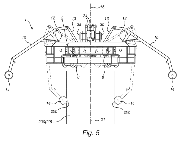
According to the invention, coupling tool 1 is provided with resilient arms 10
which are mounted
on two positions, which are opposing relative to the centre of the cross, on
transverse beams 11
arranged between two beams (2a, 2b). The connection to transverse beams 11
runs via hinges 12,
as shown in figure 5. Also according to figure 5, the arms can be moved from a
shown starting
position to a position against a wall part 20b of the outer end 200 of tubular
element 20 for the
purpose of aligning the suspended coupling tool 1 relative to outer end 200.
Arms 10 here take on
the position shown with broken lines. In the shown embodiment rotation of arms
10 relative to
support structure 2 is done by imparting a movement on hydraulic cylinders 13
arranged between
arms 10 and support structure 2. The resilient arms 10 forming part of
coupling tool 1 here have a
sufficiently great length to be able to be first to come into contact with the
outer end 200 of the
element to be upended.
Arms 10 are provided at a free outer end with rolling bodies 14 which come
into contact with wall
part 10b during use. Rolling bodies 14 ensure that the outer ends of arms 10
can move more easily
over wall part 20b in the longitudinal direction 21 in order to thus seek the
correct aligned position.
Rolling bodies 14 can rotate in their rotation direction round a shaft
connection 140.
The resilient force with which resilient arms 10 with rolling bodies 14 are
held against wall part
20b is determined by the pressure in hydraulic cylinders 13. Hydraulic
cylinders 13 do provide a
certain counter-pressure when arms 10 are held against wall part 10b. This
counter-pressure should
not be too high so as to avoid damage by, and to, resilient arms 10.
Coupling tool 1 further comprises clamping members 6 slidable along the beams
(2a, 2b) from a
clear position to a clamping position. Each camping member 6 has a U-shaped
cross-section and
can in this way at least partially enclose a beam (2a, 2b) so that clamping
member 6 is able to slide
with sliding surfaces over the relevant beam (2a, 2b) without losing contact
with the beam (2a, 2b).
In the shown embodiment clamping members 6 are slidable along a lower side of
support structure
2. The lower side of support structure 2 is defined here as the side where
lifting member 4 is not
situated. This lifting member 4 is situated on an upper side of the cross-
shaped support structure 2.
Clamping members 6 can be slid over the beams (2a, 2b) by means of hydraulic
piston cylinders 7
CA 03107185 2021-01-21
WO 2020/020821 PCT/EP2019/069674
extending between a relevant clamping member 6 and a beam of support structure
2. By imparting
on the cylinders a radially outward movement in the indicated directions 8 as
according to figure 2
the clamping members 6 are moved from a clear position A lying radially
relatively close to the
centre of the cross to a clamping position B located further away from the
centre of the cross of the
5 support structure. As shown in figure 3, in the clamping position B
clamping members 6 lie under
pressure against internal wall parts 20a of a hollow outer end of foundation
pile 20, wherein a
clamping member part is slid under a flange or protruding edge (not shown) of
the foundation pile.
This results in a mechanical coupling, optionally combined with a friction
coupling between end
surfaces of clamping members 6 and the internal wall parts 20a of foundation
pile 2. In order to
10 further improve this coupling the end surfaces of clamping members 6
which come into contact
with wall parts 20a can be provided with shock-absorbing elements such as
rubber covering. The
figures further show that in the clamping position of clamping members 6 the
beams (2a, 2b)
extend substantially transversely of a longitudinal direction 21 of foundation
pile 20. In figure 3 the
longitudinal direction 21 runs perpendicularly of the plane of the figure.
Coupling tool 1 is further provided with support members 9 connected to a beam
(2a, 2b). Support
members 9 are configured to support outer wall parts 20b of foundation pile
20, at least along parts
of the periphery of foundation pile 20. Support members 9 likewise have a U-
shaped cross-section
and can be slid over end parts of the beams (2a, 2b) to an adjustable fixed
position of the relevant
beam (2a, 2b). The adjustable fixed positions are for instance determined by a
number of openings
22 which are arranged in a side wall of a beam (2a, 2b) and in which a
corresponding pin 92 of a
support member 9 can be arranged in order to secure this member to the beam
(2a, 2b). Because
support members 9 are configured to support an outer wall part 20b of
foundation pile 20 during
upending, support members 9 will generally be situated more radially outward
in the radial
direction 8 than clamping members 6, which are after all configured in the
shown embodiment to
clamp an inner wall part 20a of foundation pile 20 during upending.
For foundation piles 20 with relatively large diameters, for instance of 6 m
and more, and/or a
relatively high weight, for instance 800-2300 tons and more, it may be useful
to provide further
support in the form of a support structure 25, which differs from support
members 9 and extends
along at least a part of the periphery of foundation pile 20. In order to
obtain sufficient strength it
may be useful to connect support structure 25 to at least two beams (2a, 2b),
as shown in figures 2
and 3. The surfaces of support structure 25 which can come into contact with
wall parts of
foundation pile 20 can also be provided with shock-absorbing elements 26, for
instance in the form
of rubber covering.
CA 03107185 2021-01-21
WO 2020/020821 PCT/EP2019/069674
11
During use, when foundation pile 20 is being upended, both support members 9
and support
structure 25 are situated on a lower side of foundation pile 20 in partially
upended position.
Support members 9 and, if desired, support structure 25, are therefore
particularly useful in
absorbing the own weight of foundation pile 20.
Finally, coupling tool 1 can also be provided with means for adjusting the
angular position of
support structure 2 relative to the lifting member 4 which is connected
pivotally to support
structure 2. In the shown embodiment the angle adjusting means comprise
hydraulic piston
cylinders 24 extending between lifting member 4 and support structure 2. In
the extended position
of cylinders 24, shown in figure 4, the plane 29 of support structure 2 runs
substantially parallel to
the plane 49 of lifting member 4. In this lifting position the angle 45
between the two planes of
lifting member 4 and support structure 2 amounts to substantially 0 degrees.
By retracting
cylinders 24 the support structure 2 is rotated round rotation axis 5 (see
figure 2) from the insertion
position shown in figure 4 to the hanging position shown with broken lines in
the same figure.
Plane 29 of support structure 2 runs here substantially perpendicular to the
plane of lifting member
4. The angle 45 between lifting member 4 and support structure 2 has here
increased to about 90
degrees.
During use the invented coupling tool 1 is firstly connected to a hoisting
cable (not shown) of a
crane (not shown) by connecting the hoisting cable to the eye 40 or
alternative connecting means
of lifting member 4. Support structure 2 is then taken up by lifting member 4
using the crane and
carried to an outer end of foundation pile 20. Foundation piles 20 which have
to be upended and
for instance have to be arranged in a seabed are generally situated on the
work deck of a vessel, for
instance a jack-up platform, in horizontal position. In order to lift such a
horizontally oriented
foundation pile 20 with coupling tool 1 the support structure 2 of the device
is moved into the
insertion position shown with full lines in figure 4, and inserted into a
hollow outer end of
foundation pile 20, by imparting a movement on cylinders 24. Clamping members
6 are here in the
clear position A, i.e. relatively close to the centre of the cross.
According to the invention, insertion of coupling tool 1 takes place using the
resilient arms 10. The
resilient arms 10 forming part of coupling tool 1 are moved from the rest
position shown in figure
5 to a position lying closer to the wall part 20b to be touched. In this
situation the coupling tool 1
swings to some extent because it is suspended from the crane. After arms 10
have approached wall
part 20b sufficiently, arms 10 are first to come into contact with the outer
end 200 to be upended,
wherein the resilience ensures that coupling tool 1, and more particularly the
support structure 2
provided with the coupling means 6, is aligned relative to outer end 200.
Because resilient arms 10
CA 03107185 2021-01-21
WO 2020/020821 PCT/EP2019/069674
12
have been placed against wall part 20b of outer end 200, they are able to move
thereover by
rotation of rolling bodies 14. Coupling tool 1, particularly support structure
2, is co-displaced in
this movement so that it is aligned with outer end 200. The axis 15 running
perpendicularly of the
plane 29 of the support structure hereby comes to lie substantially parallel
to the longitudinal
direction 21 of the element to be upended. This alignment allows coupling
means 6 to be
positioned such that they are able to engage outer end 200 without much risk
of unexpected
movements which could cause damage to the element, particularly to foundation
pile 20.
Clamping members 6 are then slid along the beams (2a, 2b) from their clear
position A to their
clamping position B, wherein a coupling with the internal wall parts 20a of
the hollow outer end of
foundation pile 2 is realized. In this clamping position the beams (2a, 2b)
extend substantially
transversely of the longitudinal direction of foundation pile 20. The
foundation pile 20 coupled to
device 1 is then upended by hoisting the whole with the crane. Support
structure 2 here pivots
relative to lifting member 4 until angle 45 has been reduced to 90 degrees, in
other words until
plane 29 of support structure 2 runs substantially perpendicular to plane 49
of lifting member 4. In
this position the foundation pile 20 coupled to device 1 is hoisted with the
crane into a desired
position, for instance there where foundation pile 20 has to be lowered onto
the seabed. In the
desired position clamping members 6 are then slid radially inward along the
beams (2a, 2b) from
clamping position B to clear position A in order to uncouple device 1 from
foundation pile 20.
During upending of foundation pile 20 it can if desired be supported further
by support members 9
and/or support structure 25.
It will be apparent that the above described embodiments have to be provided
with peripheral
equipment, such as for instance hydraulic and electric power sources, supply
conduits therefor, and
the like. This peripheral equipment is not described in further detail.
With the embodiment of the invented device, described above in detail, a
tubular object,
particularly a foundation pile of a wind turbine, can be placed from a
floating vessel onto a ground
surface, particularly an underwater bottom, this in worse weather conditions
than is possible with
the known method. This reduces the risk of damage to the tubular object. The
device also makes it
possible to manipulate tubular elements with relatively large dimensions,
wherein different
dimensions can be accommodated.