Note: Descriptions are shown in the official language in which they were submitted.
CA 03107656 2021-01-26
WO 2020/035274 PCT/EP2019/069918
1
TITLE: APPARATUS FOR CLEARING TRASH FROM A SOIL SURFACE
DESCRIPTION
The present invention relates to apparatus for clearing trash from a soil
surface, and
particularly but not exclusively to apparatus configured to be used without
any form of
cooperating scraper.
With the reduction of inversion soil tillage such as min-till, strip-till, no-
till and zero-
till, often the previous crop residue or weed growth is present on the surface
at the time of
sowing the next crop. This can cause problems with surface tillage or seed
sowing operations
due to crop residue and weeds (hereinafter "trash") becoming entangled with
ground-
engaging parts of the cultivator or seed drill. Also, particularly with
seeding operations that
are carried out using rotating soil openers such as cutting discs, trash
present on the soil
surface can be deflected into the soil by the periphery edge of the cutting
disc as it enters the
soil to create an opening for seed to be placed, resulting in unwanted organic
material being
introduced into the opening and coming into contact with the seed. This is
known as "hair-
pinning" and causes problems of rotting and/or toxicity with seed which then
has a
detrimental effect on germination, establishment and growth of the crop. It is
therefore highly
desirable prior to performing cultivating or sowing operations to mechanically
clear the soil
surface of trash along the path of the cultivating or seed sowing tool. This
is particularly
important in soft or wet soil conditions as the trash is more likely to be
pushed into the soil
than cut through and left on the surface.
CA 03107656 2021-01-26
WO 2020/035274 PCT/EP2019/069918
2
Known methods for displacing trash typically involve the use of ground-driven
toothed wheels or concave discs mounted to rotate about a horizontal axis. The
horizontal
axis are typically angled relative to the direction of travel with the ground-
engaging part of
the wheel or disc coming into contact with the soil surface ahead and line
with the cultivating
or sowing device. The problem with these wheel and disc arrangements is that
it is difficult
to achieve an area of sufficient width without a degree of entry into the soil
due to the radius
effect causing a curvature at point of contact with the soil and limitation of
angle to the
direction of travel because of the need for sufficient ground contact to
induce self-rotation.
Too great an angle causes excessive distance of material throw, especially at
higher speeds.
Some of these problems can be overcome by using pairs of toothed wheel or
concave disc
arrangements per row, usually set to displace the material to opposed lateral
directions. This
still has the complication of uncontrolled throw and increases the complexity
and cost.
The present applicant has identified the need for an improved trash clearance
device that
overcomes or at least alleviate problems associated with the prior art.
In accordance with a first aspect of the present invention, there is provided
apparatus for
clearing trash (e.g. crop residue or weeds) from a soil surface, the apparatus
being configured to
be mounted on a towable frame support and driven across the soil surface in a
direction oftravel,
the apparatus comprising: a support; and a soil-engaging member (e.g. tool or
share) rotatably
mounted to the support, wherein the soil-engaging member is orientated to
rotate about an axis
tilted from a perpendicular to the soil surface by an acute angle (e.g. first
acute angle) towards
one lateral side relative to the direction of travel, whereby contact between
the soil-engaging
member and the soil surface induces rotation of the soil-engaging member
around the axis.
In this way, a near upright self-rotating soil surface scraper/soil surface
residue remover
is provided for use in clearing trash from along a furrow path or clearing
weeds between adjacent
furrows. Advantageously, the upright position of the soil-engaging member
provides an
effective trash clearance action with minimal soil disruption.
Typically the soil-engaging member is configured to operate without the
interaction of
a cooperating device to achieve trash clearance. For example, the soil-
engaging member may
be configured to operate to clear trash without the need for a cooperating
scraper (e.g. a
scraperless trash clearing apparatus)
In one embodiment, the acute angle is in the range 10 -35 (e.g. 15 -25 ).
In one embodiment, the axis is additionally tilted at a second acute angle
towards the
front relative to the direction of travel.
CA 03107656 2021-01-26
WO 2020/035274 PCT/EP2019/069918
3
In one embodiment, the second acute angle is in the range 10 -35 (e.g. 15 -25
).
In one embodiment, the first acute angle is substantially equal to the second
acute angle.
In one embodiment, the soil-engaging member comprises a central shaft.
In one embodiment, the support comprises a bearing housing comprising a
bearing
operative to rotatably support an (e.g. upper) end part of the central shaft
(e.g. end shaft) of the
soil-engaging member.
In one embodiment, the soil-engaging member defines a trash displacement
surface
operative to displace trash to one lateral side relative to the direction of
travel.
In one embodiment, the central shaft defines a passageway (e.g. delivery
passageway)
for delivering material (e.g. particulate material such as seed or fertilizer
or a liquid) to an outlet
(e.g. outlet provided on the central shaft).
In one embodiment, the outlet is located at a lowermost part of the central
shaft.
Depending upon the length of the central shaft the outlet may be located at or
near a lowermost
portion of the soil-engaging member or at a position raised from the lowermost
portion.
In one embodiment the soil-engaging member defines a rotary body (e.g.
defining the
trash displacement surface) connected to the central shaft.
In one embodiment, the rotary body defines a further passageway for receiving
material
from the passageway in the central shaft. In this embodiment, the outlet may
be provided on
the rotary body (e.g. provided at a lowermost portion of the rotary body).
In one embodiment, the further passageway is configured to receive a lower end
of the
central shaft.
In one embodiment, the central shaft (e.g. end part of the central shaft)
defines an inlet
for receiving material from a delivery tube.
In one embodiment, the apparatus further comprises a connector for connecting
the
delivery tube to the support or to the soil-engaging member.
In one embodiment, the connector comprises a bracket for mounting the delivery
tube
to the support (e.g. to the bearing housing).
In one embodiment, the connector further comprises a connecting part having a
leading
end configured to extend into the passageway of the central shaft and deliver
material from the
delivery tube into the passageway. In one embodiment a trailing end of the
connecting part is
configured to extend into the delivery tube.
In one embodiment, a lower part of the central shaft forms a central elongate
stem.
In one embodiment, the trash displacement surface is provided at a lower
portion (e.g.
CA 03107656 2021-01-26
WO 2020/035274 PCT/EP2019/069918
4
lowermost portion) of the soil-engaging member and separated from the support
by the central
elongate stem.
In one embodiment, the central elongate stem defines an area of revolution
substantially
smaller than an effective (e.g. mean) area of revolution of the support (i.e.
the area of the swept
shape formed by rotation of radially outermost parts of the central elongate
stem when rotating
around the axis is substantially smaller in area than the equivalent swept
shape that would be
formed by rotation of radially outermost parts of the support about the same
axis).
In one embodiment, the trash displacement surface is configured to deflect
away trash
attempting to rise up the soil-engaging member. In this way, the trash
displacement member is
configured to keep trash low and away from the support (e.g. by deflecting the
trash downwards
or sideways).
In one embodiment, a degree of trash deflection is achieved by providing the
trash
displacement surface that extends from a lower portion (e.g. lowermost
portion) of the body to
an upper portion (e.g. uppermost potion) adjacent the support. In one
embodiment an upper
portion of the trash displacement surface may longitudinally overlap a leading
portion of the
support.
In one embodiment, an upper portion (e.g. uppermost portion) of the trash
displacement
surface defines an area of revolution (i.e. area of the swept shape formed by
rotation of radially
outermost parts of the surface when rotating around the axis) substantially
equal to or greater
than an effective (e.g. mean) area of revolution of the support.
In one embodiment, the trash displacement surface has an area of revolution
that
increases with reduced distance from the support (e.g. increasing from a lower
portion (e.g.
lowermost portion) to an upper portion (e.g. uppermost portion)).
In one embodiment the change in the area of revolution between the lower
portion (e.g.
lowermost portion) and the upper portion (e.g. uppermost portion) is
associated with a
substantially constant taper angle. In one embodiment the taper angle is in
the range 10 -35
(e.g. 15 -25 ). In one embodiment the taper angle is substantially equal to
the first angle.
In a first set of embodiments, the trash displacement surface is a continuous
surface.
In one embodiment, the trash displacement surface is a substantially
cylindrical surface.
In one embodiment, the trash displacement surface is a frusto-conical surface.
In one
embodiment, the frusto-conical surface is orientated such that the cross-
sectional area (and
hence area of revolution) of the frusto-conical surface increases with reduced
distance from the
support (e.g. increases from a lower portion to an upper portion).
CA 03107656 2021-01-26
WO 2020/035274 PCT/EP2019/069918
In a second set of embodiment, the trash displacement surface is a
discontinuous surface.
In one embodiment, the trash displacement surface comprises a plurality of
circumferentially-spaced projections.
In one embodiment, the trash displacement surface comprises a plurality of
5 circumferentially-spaced vanes extending radially from a central stem.
In one embodiment, the vanes have a radial length that increases with reduced
distance
from the support (e.g. increases from a lower portion of the vane to an upper
portion of the vane,
e.g. to define a frusto-conical profile when rotating).
In one embodiment, the plurality of vanes comprises 3 or more vanes (e.g. 4 or
more
vanes).
In one embodiment, the vanes are substantially equally spaced
circumferentially.
In one embodiment an upper portion of the vanes enclose a leading portion of
the
support.
In one embodiment, the trash displacement surface comprises a plurality of
circumferentially spaced axially extending tines extending from a support
frame (e.g. extending
downwards from an upper support frame).
In one embodiment the support frame comprises a plurality of radially
extending arm
portions, each arm portion supporting an individual tine.
In one embodiment, the plurality o f tines comprises 3 or more tines (e.g. 4
or more tines).
In one embodiment, the tines are substantially equally spaced
circumferentially.
In one embodiment, a lowermost part of the soil-engaging member defines a
protuberant
cutting rim (e.g. circular disc or plate) projecting from a central body
portion of the member and
configured to partially penetrate the soil (e.g. to a pre-defined first
depth). Typically the central
body portion of the member defines a trash displacement surface (e.g. as
previously defined).
In another embodiment, the central body portion of the member comprises a stem
supporting
the protuberant cutting rim.
In one embodiment, the apparatus further comprises a trailing arm assembly
mounted to
the support and operative to allow the soil engaging member to follow ground
contour
variations. In one embodiment, the trailing arm assembly is operative to
maintain a
predetermined orientation of the axis relative to the ground. For example, the
trailing arm
assembly may comprise a parallel linkage assembly.
In one embodiment, the apparatus is biased to maintain a downward force on
soil-
engaging member (e.g. to maintain suitable ground pressure). The biasing
action may be
CA 03107656 2021-01-26
WO 2020/035274 PCT/EP2019/069918
6
provided by one or more of a spring bias device, a hydraulic bias device, and
a pressurised air
bias device.
In accordance with a second aspect of the present invention, there is provided
a frame
assembly for towing along a soil surface on which there is mounted apparatus
for clearing trash
as defined in any embodiment of the first aspect of the present invention.
Embodiments of the present invention will now be described by way of example
with
reference to the accompanying drawings in which:
Figure lA is a schematic front view of a trash clearing assembly in accordance
with a
first embodiment of the present invention;
Figure 1B is a schematic side view of the trash clearing assembly of Figure
1A;
Figure 2A is a schematic front view of a trash clearing assembly in accordance
with a
second embodiment of the present invention;
Figure 2B is a schematic side view of the trash clearing assembly of Figure
2A;
Figure 3A is a schematic front view of a trash clearing assembly in accordance
with a
third embodiment of the present invention;
Figure 3B is a schematic side view of the trash clearing assembly of Figure
3A;
Figure 4A is a schematic front view of a trash clearing assembly in accordance
with a
fourth embodiment of the present invention;
Figure 4B is a schematic side view of the trash clearing assembly of Figure
4A;
Figure 5A is a schematic front view of a trash clearing assembly in accordance
with a
fifth embodiment of the present invention;
Figure 5B is a schematic side view of the trash clearing assembly of Figure
5A;
Figure 6A is a schematic front view of a trash clearing assembly in accordance
with a
sixth embodiment of the present invention;
Figure 6B is a schematic side view of the trash clearing assembly of Figure
6A;
Figure 7A is a schematic front view of a trash clearing assembly in accordance
with a
seventh embodiment of the present invention;
Figure 7B is a schematic side view of the trash clearing assembly of Figure
7A;
Figure 8A is a schematic front view of a trash clearing assembly in accordance
with an
eighth embodiment of the present invention; Figure 8B is a schematic side view
of the trash
clearing assembly of Figure 8A;
Figure 9A is a schematic side view of a trash clearing assembly in accordance
with a
further embodiment of the present invention including material delivery
functionality; and
CA 03107656 2021-01-26
WO 2020/035274 PCT/EP2019/069918
7
Figure 9B is a schematic cross-sectional view of parts of the trash clearing
assembly of
Figure 9A illustrating the material delivery functionality.
Figures 1A-B show a scraperless trash clearing assembly 110 mounted to a
horizontally
extending member 120 of a towable frame supporting a cultivating or seed
sowing implement
and operative to clear trash (e.g. crop residue or weeds) from a soil surface
"S" when driven
across the soil surface in a direction of travel "D".
Trash clearing assembly 110 comprises: a support in the form of a cylindrical
bearing
housing 130; a soil-engaging member or "rota" 140 freely rotatably mounted in
the bearing
housing 130 via an end shaft 142; and a ground tracking trailing arm assembly
150 operative to
pivotally connect bearing housing 130 to horizontally extending member 120.
As illustrated in Figure 1A, soil-engaging member 140 is orientated to rotate
about a
near vertical axis "A" tilted from a perpendicular to the soil surface "B" by
an first acute angle
01 towards one lateral side relative to the direction of travel "D". This
slightly offset angle
results in contact between the soil-engaging member 140 and the soil surface
inducing rotation
of the soil-engaging member 140 around the axis "A". As illustrated in Figure
1B, axis "A" is
further tilted by a second acute angle 02 in a forward direction relative to
the direction of travel
"D" such that contact with the soil surface occurs forward of the centre of
rotation in the
direction of travel thereby ensuring smooth operation. In this example, the
first and second
acute angles 01, 02 are substantially identical and each substantially 20 .
Soil-engaging member 140 defines a trash displacement surface 144 operative in
use to
displace trash to one lateral side of the assembly 110 relative to the
direction of travel "D" and
additionally to deflect trash attempting to rise up the soil-engaging member
140 downwards and
sideways and away from bearing housing 130/trailing arm assembly 150.
Trash displacement surface 144 is provided by four substantially equally
circumferentially-spaced vanes 146 extending radially from a central stem 148.
The vanes 146
have a radial length that increases in length from a lower portion of the vane
146A to an upper
portion of the vane 146B to define a frusto-conical outer profile when under
rotation. This
frusto-conical outer profiles defines an area of revolution around axis "A"
which steady
increases with distance from the lower portion. As illustrated, the upper
portion of the vanes
146B are sufficiently radially extended to enclose a leading portion 130A of
bearing housing
130.
Trailing arm assembly 150 comprises a parallel linkage 152 operative to allow
the soil-
engaging member 140 to follow the ground contour variation whilst maintain a
predetermined
CA 03107656 2021-01-26
WO 2020/035274 PCT/EP2019/069918
8
orientation of the axis "A" relative to the ground. The trailing arm assembly
150 may be
configured to provide a biasing action (e.g. using a spring, hydraulic, or
pressurised air biasing
device - not shown) to maintain a downward force on soil-engaging member 140
in order to
maintain suitable ground pressure to ensure dependable ground-driven rotation.
The geometry of soil-engaging member 140 is design such that the width at the
lower
ground contact point sufficient to induce a rotation action due to the ground
contact being
offset from the centre line of the pivot axis "A" ¨ typically upwards from
30mm. This offset
from the centre line could be formed by any solid part of the circumference
such as the shaft,
tube or cone being large enough to be sufficiently offset to induce rotation.
However, the
inclusion of projecting vanes 146 has been found to be particularly
effectively since the
projections assist rotation and trash engagement.
Figures 2A-B show a scraperless trash clearing assembly 210 mounted to a
horizontally
extending member 220 of a towable frame supporting a cultivating or seed
sowing implement
and operative to clear trash (e.g. crop residue or weeds) from a soil surface
"S" when driven
across the soil surface in a direction of travel "D".
Trash clearing assembly 210 comprises: a support in the form of a cylindrical
bearing
housing 230; a soil-engaging member or "rota" 240 freely rotatably mounted in
the bearing
housing 230 via an end shaft 242; and a ground tracking trailing arm assembly
250 operative to
pivotally connect bearing housing 230 to horizontally extending member 220.
As illustrated in Figure 2A, soil-engaging member 240 is orientated to rotate
about a
near vertical axis "A" tilted from a perpendicular to the soil surface "B" by
an first acute angle
01 towards one lateral side relative to the direction of travel "D". This
slightly offset angle
results in contact between the soil-engaging member 240 and the soil surface
inducing rotation
of the soil-engaging member 240 around the axis "A". As illustrated in Figure
1B, axis "A" is
further tilted by a second acute angle 02 in a forward direction relative to
the direction of travel
"D" such that contact with the soil surface occurs forward of the centre of
rotation in the
direction of travel thereby ensuring smooth operation. In this example, the
first and second
acute angles 01, 02 are substantially identical and each substantially 20 .
Soil-engaging member 240 defines a trash displacement surface 244 operative in
use to
displace trash to one lateral side of the assembly 210 relative to the
direction of travel "D" and
additionally to deflect trash attempting to rise up the soil-engaging member
240 downwards and
sideways and away from bearing housing 230/trailing arm assembly 250.
Trash displacement surface 244 comprises four substantially equally
circumferentially-
CA 03107656 2021-01-26
WO 2020/035274 PCT/EP2019/069918
9
spaced axially extending tines 246 extending downwardly from a cruciform upper
support frame
248.
As in the first embodiment, trailing arm assembly 250 comprises a parallel
linkage 252
operative to allow the soil-engaging member 240 to follow the ground contour
variation whilst
maintain a predetermined orientation of the axis "A" relative to the ground.
Again, the trailing
arm assembly 250 may be configured to provide a biasing action (e.g. using a
spring, hydraulic,
or pressurised air biasing device - not shown) to maintain a downward force on
soil-engaging
member 240 in order to maintain suitable ground pressure to ensure dependable
ground-driven
rotation.
Figures 3A-B show a scrap erless trash clearing assembly 310 mounted to
horizontally
extending member 320 of a towable frame supporting a cultivating or seed
sowing implement
and operative to clear trash (e.g. crop residue or weeds) from a soil surface
"S" when driven
across the soil surface in a direction of travel "D".
Trash clearing assembly 310 comprises: a support in the form of a cylindrical
bearing
housing 330; a soil-engaging member or "rota" 340 freely rotatably mounted in
the bearing
housing 330 via an end shaft 342; and a ground tracking trailing arm assembly
350 operative to
pivotally connect bearing housing 330 to horizontally extending member 320.
As illustrated in Figure 3A, soil-engaging member 340 is orientated to rotate
about a
near vertical axis "A" tilted from a perpendicular to the soil surface "B" by
an first acute angle
01 towards one lateral side relative to the direction of travel "D". This
slightly offset angle
results in contact between the soil-engaging member 340 and the soil surface
inducing rotation
of the soil-engaging member 340 around the axis "A". As illustrated in Figure
1B, axis "A" is
further tilted by a second acute angle 02 in a forward direction relative to
the direction of travel
"D" such that contact with the soil surface occurs forward of the centre of
rotation in the
direction of travel thereby ensuring smooth operation. In this example, the
first and second
acute angles 01, 02 are substantially identical and each substantially 20 .
Soil-engaging member 340 defines a continuous frusto-conical trash
displacement
surface 344 orientated such that the cross-sectional area of the frusto-
conical surface increases
from a lower portion 344A to an upper portion 344B. In use trash displacement
surface 344 is
operative in use to displace trash to one lateral side of the assembly 310
relative to the direction
of travel "D" and additionally to deflect trash attempting to rise up the soil-
engaging member
340 downwards and sideways and away from bearing housing 330/trailing arm
assembly 350.
As in the first embodiment, trailing arm assembly 350 comprises a parallel
linkage 352
CA 03107656 2021-01-26
WO 2020/035274 PCT/EP2019/069918
operative to allow the soil-engaging member 340 to follow the ground contour
variation whilst
maintain a predetermined orientation of the axis "A" relative to the ground.
As before, the
trailing arm assembly 350 may be configured to provide a biasing action (e.g.
using a spring,
hydraulic, or pressurised air biasing device - not shown) to maintain a
downward force on soil-
5 engaging member 340 in order to maintain suitable ground pressure to ensure
dependable
ground-driven rotation.
Figures 4A-B show a scraperless trash clearing assembly 410 mounted to a
horizontally
extending member 420 of a towable frame supporting a cultivating or seed
sowing implement
and operative to clear trash (e.g. crop residue or weeds) from a soil surface
"S" when driven
10 across the soil surface in a direction of travel "D".
Trash clearing assembly 410 comprises: a support in the form of a cylindrical
bearing
housing 430; a soil-engaging member or "rota" 440 freely rotatably mounted in
the bearing
housing 430 via an end shaft 442; and a ground tracking trailing arm assembly
450 operative to
pivotally connect bearing housing 430 to a horizontally extending member 420.
As illustrated in Figure 4A, soil-engaging member 440 is orientated to rotate
about a
near vertical axis "A" tilted from a perpendicular to the soil surface "B" by
an first acute angle
01 towards one lateral side relative to the direction of travel "D". This
slightly offset angle
results in contact between the soil-engaging member 440 and the soil surface
inducing rotation
of the soil-engaging member 440 around the axis "A". As illustrated in Figure
1B, axis "A" is
further tilted by a second acute angle 02 in a forward direction relative to
the direction of travel
"D" such that contact with the soil surface occurs forward of the centre of
rotation in the
direction of travel thereby ensuring smooth operation. In this example, the
first and second
acute angles 01, 02 are substantially identical and each substantially 20 .
Soil-engaging member 440 defines a continuous cylindrical trash displacement
surface
444 operative in use to displace trash to one lateral side of the assembly 410
relative to the
direction of travel "D". The cylindrical trash displacement surface 444 has a
cross-sectional
area that is greater than that of bearing housing 430 (and accordingly a
greater area of revolution
around axis "A") to assist the deflection oftrash attempting to rise up the
soil-engaging member.
As in the first embodiment, trailing arm assembly 450 comprises a parallel
linkage 452
operative to allow the soil-engaging member 440 to follow the ground contour
variation whilst
maintain a predetermined orientation of the axis "A" relative to the ground.
As before, the
trailing arm assembly 450 may be configured to provide a biasing action (e.g.
using a spring,
hydraulic, or pressurised air biasing device - not shown) to maintain a
downward force on soil-
CA 03107656 2021-01-26
WO 2020/035274 PCT/EP2019/069918
11
engaging member 440 in order to maintain suitable ground pressure to ensure
dependable
ground-driven rotation.
In the embodiments of Figures 3A-B and 4A-B the soil-engaging members 340, 440
may be solid or hollow in construction. In the case of a hollow construction,
the soil-engaging
members 340, 440 may have a closed base (e.g. to prevent ingress of soil into
the hollow rotary
cylinder) or an open base (e.g. open-ended cylinder) that will allow some
ingress of soil into the
hollow cylinder.
Figures 5A-B show a scraperless trash clearing assembly 110' based on the
trash
clearing assembly 110 of Figures 1A-B (features in common are labelled
accordingly).
Assembly 110' differs from 110 in that a lowermost part of the trash
displacement surface 144'
comprises a domed circular cutting plate 145 with a convex upper profile and
defining a
protuberant cutting rim 145A projecting from a central body portion of the
member and
configured to partially penetrate the soil to a pre-defined first depth.
Figures 6A-B show a scraperless trash clearing assembly 310' based on the
trash
clearing assembly 310 of Figures 3A-B (features in common are labelled
accordingly).
Assembly 310' differs from 310 in that a lowermost part of the trash
displacement surface 244'
comprises a flat circular cutting plate 245 defining a protuberant cutting rim
245A projecting
from a central body portion ofthe member and configured to partially penetrate
the soil to a pre-
defined first depth.
Figures 7A-B show a scraperless trash clearing assembly 510 mounted to a
horizontally
extending member 520 of a towable frame supporting a cultivating or seed
sowing implement
and operative to clear trash (e.g. crop residue or weeds) from a soil surface
"S" when driven
across the soil surface in a direction of travel "D".
Trash clearing assembly 510 comprises: a support in the form of a cylindrical
bearing
housing 530; a soil-engaging member or "rota" 540 freely rotatably mounted in
the bearing
housing 530 via an end shaft 542; and a ground tracking trailing arm assembly
550 operative to
pivotally connect bearing housing 530 to a horizontally extending member 520.
As illustrated in Figure 7A, soil-engaging member 540 is orientated to rotate
about a
near vertical axis "A" tilted from a perpendicular to the soil surface "B" by
an first acute angle
Oi towards one lateral side relative to the direction of travel "D". This
slightly offset angle
results in contact between the soil-engaging member 540 and the soil surface
inducing rotation
of the soil-engaging member 540 around the axis "A". As illustrated in Figure
1B, axis "A" is
further tilted by a second acute angle 02 in a forward direction relative to
the direction of travel
CA 03107656 2021-01-26
WO 2020/035274 PCT/EP2019/069918
12
"D" such that contact with the soil surface occurs forward of the centre of
rotation in the
direction of travel thereby ensuring smooth operation. In this example, the
first and second
acute angles 01, 02 are substantially identical and each substantially 20 .
Soil-engaging member 540 defines a trash displacement surface 544 at a
lowermost
portion of the soil-engaging member 540 operative in use to displace trash to
one lateral side of
the assembly 510 relative to the direction of travel "D". Trash displacement
surface 544
comprises a flat circular cutting plate 545 defining a protuberant cutting rim
545A projecting
from a central body portion of the member and configured to partially
penetrate the soil to a pre-
defined first depth. As illustrated, trash displacement surface 544 is
separated from bearing
housing 530 by an elongate central stem 548.
As in the previous embodiments, trailing arm assembly 550 comprises a parallel
linkage
552 operative to allow the soil-engaging member 540 to follow the ground
contour variation
whilst maintain a predetermined orientation of the axis "A" relative to the
ground. As before,
the trailing arm assembly 550 may be configured to provide a biasing action
(e.g. using a spring,
hydraulic, or pressurised air biasing device - not shown) to maintain a
downward force on soil-
engaging member 540 in order to maintain suitable ground pressure to ensure
dependable
ground-driven rotation.
Figures 8A-B show a scraperless trash clearing assembly 510' based on the
trash
clearing assembly 510 of Figures 7A-B (features in common are labelled
accordingly).
Assembly 510' differs from 510 in that flat circular cutting plate 545 is
replaced by a domed
plate 545' having a convex rather than flat upper profile.
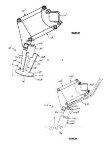
Figures 9A-B show a scraperless trash clearing assembly 410' based on the
trash
clearing assembly 410 of Figures 4A-B (features in common are labelled
accordingly).
As illustrated in 9B, scraperless trash clearing assembly 410' differs from
scraperless
trash clearing assembly 410 in that end shaft 442' and rotary body of soil-
engaging member
440' define first and second connected passageways 442A and 440A. A connector
600
comprising a bracket 610 and a hollow connecting tube 620 is provided to mount
a flexible
delivery tube 650 to bearing housing 430' (Figure 9B shows bearings 432 of
bearing housing
430'). As shown, connecting tube 620 is positioned with an upper end 622
inserted into flexible
delivery tube 650 and a lower end 624 inserted into first passageway 442A.
Bracket 610 has a
first end 612 mounted to bearing housing 430' and a second end 614 connected
to a central part
626 of connecting tube 620.
Together first and second passageways 442A, 440A define a delivery passageway
for
CA 03107656 2021-01-26
WO 2020/035274 PCT/EP2019/069918
13
delivering material (e.g. particulate material such as seed or fertilizer or a
liquid from a supply)
to an outlet 440B provided at a lowermost portion of soil-engaging member
440'.
Although the material delivery functionality has been illustrated in the
context of a trash
clearing assembly based on the trash clearing assembly 410 of Figures 4A-B,
the skilled person
will understand that the same material supply arrangement may be implemented
with any of the
other disclosed trash clearing assemblies by use of a hollow shaft/hollow
shaft and hollow rotary
body. Accordingly, the disclosure of the material supply arrangement is not
intended to be
limited to the specific trash clearing assembly 410'.