Note: Descriptions are shown in the official language in which they were submitted.
CA 03108749 2021-02-03
WO 2020/028920 PCT/US2019/045184
1
FIBER OPTICAL CONNECTOR WITH RETENTION FEATURE
CROSS-REFERENCE TO RELATED APPLICATIONS
[0001] This nonprovisional application claims the benefit of U.S. Provisional
Application No. 62/714,123, filed August 3, 2018, pending. The disclosure of
the prior
applications is hereby incorporated by reference herein in its entirety.
TECHNICAL FIELD
[0002] The present disclosure is directed to a fiber optical connector with a
retention feature and, more particularly, to a hardened fiber optical
connector that allows for
easy field assembly. The hardened fiber optical connector has an inner housing
that directly
attaches a preterminated optical fiber cable to a ferrule without the use of
an outer clamp shell.
BACKGROUND
[0003] Fiber optical communication systems typically use a network of fiber
optic
cables to transmit large volumes of data. Typical fiber optical connectors
include a ferrule
that supports an end portion of an optical fiber. When two fiber optical
connectors are
interconnected, end faces of the ferrules, on each connector, directly oppose
one another.
Thus, the optical fibers, which are supported by each ferrule, are also
directly opposed to
each other. Furthermore, springs in each connector bias the optical fibers
towards each other
when the connectors are in this interconnected state. An optical signal can
then be
transmitted from one optical fiber to the other optical fiber.
[0004] Traditionally, the ferrule is disposed in a ferrule holder carrier,
which is then
secured to an outer barrel. Conventional outer barrels include a clamp shell
arrangement in
order to easily fit the barrel around and over the ferrule holder carrier and
the cable. Thus,
the clamp shell may open in order to move the barrel over and around these
components. An
outer housing may then be disposed over the clamp shell in order to provide a
secure and
stable connector assembly.
CA 03108749 2021-02-03
WO 2020/028920 PCT/US2019/045184
2
[0005] It may be desirable to provide a hardened optical fiber connector that
overcomes one or more problems of conventional prior art connectors that are
recognized by
persons having ordinary skill in the art.
SUMMARY
[0006] The present disclosure is directed to a fiber optical connector that
can be
easily assembled in the field. The fiber optical connector includes a barrel,
one or more
latches, and a ferrule housing sub-assembly. The barrel includes an inner
lumen that is
configured to receive an optical fiber cable, and the barrel has a first end
and a second end.
The one or more latches extend from the first end of the barrel. Additionally,
the ferrule
housing sub-assembly includes a ferrule holder carrier that is configured to
receive a ferrule.
The latches engage with the ferrule holder carrier in order to secure the
barrel with the ferrule
housing sub-assembly.
BRIEF DESCRIPTION OF THE DRAWINGS
[0007] Features and advantages of the present disclosure are described in, and
will
be apparent from, the following Brief Description of the Drawings and Detailed
Description.
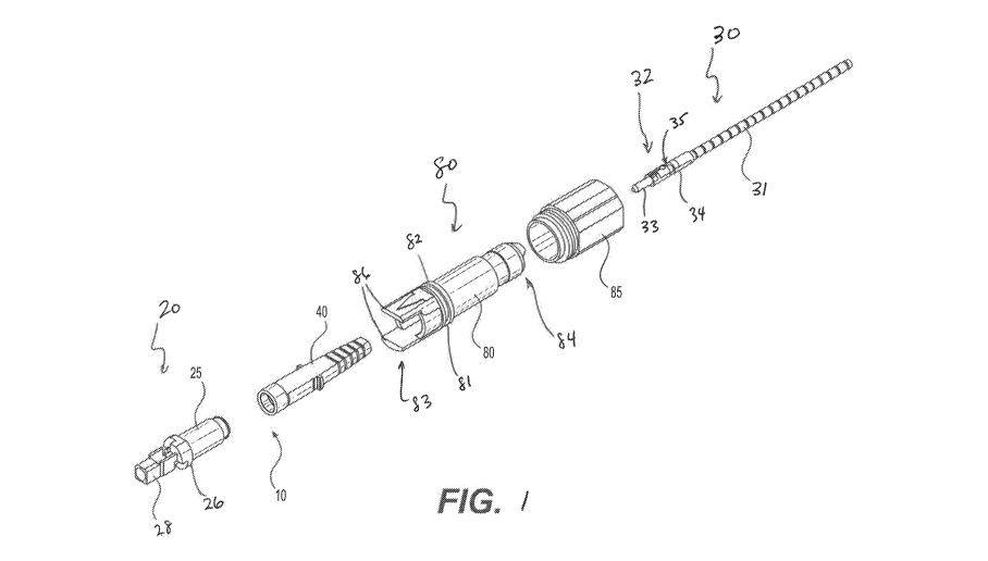
[0008] FIG. 1 is an exploded perspective view of an exemplary connector in
accordance with various aspects of the disclosure;
[0009] FIG. 2 is a perspective view of the inner housing and preconnectorized
cable
of the exemplary connector of FIG. 1;
[0010] FIG. 3 is a side cross-sectional view of the inner housing and
preconnectorized cable of the exemplary connector of FIG. 1;
[0011] FIG. 4 is a perspective view of the inner housing and boot of the
exemplary
connector of FIG. 1;
[0012] FIG. 5 is a perspective view of the inner housing of the exemplary
connector
of FIG. 1;
[0013] FIG. 6 is a side cross-sectional view of the exemplary connector of
FIG. 1;
CA 03108749 2021-02-03
WO 2020/028920 PCT/US2019/045184
3
[0014] FIG. 7 is a side cross-sectional view of another exemplary connector in
accordance with various aspects of the disclosure;
[0015] FIG. 8 is a partially-exploded perspective view of another exemplary
connector in accordance with various aspects of the disclosure;
[0016] FIG. 9 is a side cross-sectional view of the exemplary connector of
FIG. 8;
[0017] FIG. 10 is a perspective view of the inner housing of the exemplary
connector of FIG. 8.
DETAILED DESCRIPTION OF EMBODIMENTS
[0018] Throughout the description, like reference numerals will refer to like
parts in
the various drawing figures. As a preface to the detailed description, it
should be noted that,
as used in this specification and the appended claims, the singular forms "a",
"an" and "the"
include plural referents, unless the context clearly dictates otherwise.
[0019] FIGS. 1-6 illustrate an exemplary hardened fiber optical connector 10
in
accordance with various aspects of the disclosure. As shown in FIG. 1, the
connector 10
includes an inner housing 20, a preterminated fiber optic cable 30, a boot 40,
a shroud 80, and
a coupling nut 85. The preterminated fiber optic cable 30 may be, for example,
a Miniflex
QuikPush fiber cable, as illustrated and described in U.S. Patent No.
8,439,577, which is
incorporated herein by reference.
[0020] As illustrated in FIG. 2, the inner housing 20 extends from a first end
21 to a
second end 22 along a longitudinal axis X and includes a barrel portion 25, a
mid-section 26,
a latching portion 27, and a connector shell portion 28. The connector shell
portion 28 is at
the first end 21 of the inner housing 20, the barrel portion 25 is at the
second end 22 of the
inner housing 20, and the mid-section 26 and latching portion 27 are between
the connector
shell portion 28 and the barrel portion 25 in the longitudinal direction.
[0021] As illustrated in FIG. 3, the barrel portion 25 includes a reduced
diameter
portion 25a and one or more barbs 29 configured to couple with the boot 40.
The barrel
CA 03108749 2021-02-03
WO 2020/028920 PCT/US2019/045184
4
portion 25 includes a throughbore 25b extending in the longitudinal direction.
The
throughbore 25b is configured to receive the preterminated fiber optic cable
30 and allow the
preterminated cable 30 to pass therethrough into the connector shell portion
28. As shown in
Figs. 1 and 3, the barb 29 may include a ridge that projects radially outward
from the second
end 22 of inner housing 20. In some embodiments, one barb 29 may be provided
on barrel
portion 25. In other embodiments, two or more barbs 29 may be provided on
barrel portion
25. It is also contemplated that the barb 29 may include any other well-known
method to
secure boot 40 with the barrel portion 25. As shown in Fig. 2, boot 40 may be
disposed over
and around the barb 29. The boot 40 may be a flexible member that allows an
interface
between connector 10 and optical fiber cable 30 to bend and rotate. For
example, the boot 40
may be formed from a flexible material such as KRAYTON.
[0022] The preterminated fiber optic cable 30 includes a fiber optic cable 31
preterminated by a fiber connector 32, which includes a ferrule 33, and a
ferrule holder 34, as
would be understood by persons of ordinary skill in the art. The optical fiber
cable 31 holds a
single strand of 1251.tm diameter single mode optical fiber 31a, which may be
protected by
buffering layers and an outer sheath. The optical fiber 31a is held in a bore
of the ferrule 33,
as would be understood by persons skilled in the art. The fiber connector 32
may be, for
example, a PPC Balistix (QuikPush ) connector. The ferrule holder 34 includes
a neck
portion 35 formed by an annular groove 38 between a first end portion 36 and a
second end
portion 37 of the ferrule holder 34. The ferrule 33 extends from the first end
portion 36 of the
ferrule holder 34. The inner housing 20 is configured to be coupled with the
fiber connector
32, as will be described in more detail below.
[0023] As best shown in FIGS. 2, 4, and 5, the mid-section 26 includes a
portion
26a having an enlarged dimension in the longitudinal direction and having
radially-extending
flats 26b. The enlarged portion 26a and the flats 26b are configured to align
the inner
housing 20 with the shroud 80, as would be understood by persons of ordinary
skill in the art.
CA 03108749 2021-02-03
WO 2020/028920 PCT/US2019/045184
The mid-section 26 includes a throughbore 26b that continues from the
throughbore 25b of
the barrel portion 25 with a substantially same inside diameter.
[0024] The connector shell portion 28 is configured to be received by a mating
optical fiber receptacle or socket. The connector shell portion 28 may be
configured to be
received by a receptacle that is configured to receive a connector having
convenient push/pull
style mating that allows for push/pull engagement/disengagement between the
connector 10
and the mating optical fiber socket. For example, in some aspects, the
receptacle may be
configured to receive a "Subscriber Connector," or SC connector, as originally
developed by
NTT , which is well-known by persons having ordinary skill in the art.
[0025] As best illustrated in FIGS. 2-4, the latching portion 27 may be
disposed at
the mid-section 26 of the inner housing 20. The latching portion 27 includes
one or more
latches 70 that extend radially inward into the throughbore 26c of the mid-
section 26 of the
inner housing 20. As shown in FIGS. 3 and 6, the latch 70 is configured to
extend into the
annular groove forming the neck portion 35 of the ferrule holder 34. Although
FIGS. 2-4
illustrate a single latch 70, the latching portion may include two latches 70,
70' equidistantly
arranged around a circumference of the mid-section 26, as shown in FIG. 7.
Alternatively,
the latching portion 27 may include three or more latches. For example, the
latching portion
27 may include four latches disposed equidistantly around the circumference of
mid-section
26. It is further contemplated that latches may be disposed irregularly around
the
circumference of mid-section 26.
[0026] The latch 70 is configured as a cantilevered member attached at a first
end to
the mid-section and having a second free end. The latch 70 is configured to
move radially
outward upon application of an outward force and is configured to return to
its position
extending into the throughbore 26c of the mid-section 26 upon removal of the
outward force.
As a result of this configuration, the latch 70 is configured to provide a
snap-fit and/or an
interference fit with optical fiber connector sub-assembly 32. For example,
the latch 70 is
CA 03108749 2021-02-03
WO 2020/028920 PCT/US2019/045184
6
configured to be received by the neck portion 35 of the ferrule holder 34 when
the
preterminated cable 30 is received by the inner housing 20.
[0027] The shroud 80 has a first end 83 and a second end 84. The first end 83
of
the shroud 80 includes at least one opening (not numbered) defined by shroud
80. The at
least one opening extends from a medial portion of the shroud 80 to the first
end 83. In the
illustrated embodiment, the shroud 80 includes a pair of openings on opposite
sides of the
first end 83, thereby defining alignment portions or fingers 86. In some
aspects, the
alignment fingers 86 may have different shapes so that the connector 10 and
receptacle (not
shown) only mate in one orientation. The medial portion of the shroud 80 may
include a
groove 81 for seating an 0-ring (not shown). The 0-ring is configured to
provide a
weatherproof seal between the connector 10 and the receptacle (not shown) or
protective cap
(not shown) that is configured to cover a front end of the shroud 80 and the
ferrule 33. The
medial portion may also include a shoulder 82 that provides a stop for the
coupling nut 85.
The coupling nut 85 has a passageway sized so that it fits over the second end
84 of the
shroud 80 and easily rotates about the medial portion of shroud 80. In other
words, the
coupling nut 85 cannot move beyond the shoulder 82, but the coupling nut 85 is
able to rotate
with respect to shroud 80.
[0028] To assemble the connector 10, the coupling nut 85, the shroud 80, and
the
boot 40 are moved over the preconnectorized cable 30. Viewed differently, the
preconnectorized cable 30 is pushed through the coupling nut 85, the shroud
80, and the boot
40 such that coupling nut 85 is furthest from the ferrule 33 and the boot 40
is nearest the
ferrule 33. The preconnectorized cable 30 is then pushed into the inner
housing 20 until the
first end portion 36 of the ferrule holder 34 reaches the latching portion 27.
The first end
portion 36 of the ferrule holder 34 includes a ramped surface 36a that is
configured to urge
the latch 70 radially outward as the preconnectorized cable 30 is further
pushed toward the
first end 21 of the inner housing 20. When the annular groove 38 at the neck
portion 35 of
CA 03108749 2021-02-03
WO 2020/028920 PCT/US2019/045184
7
the ferrule holder 34 reaches the latch 70, the latch returns to its position
extending into the
throughbore 26c of the mid-section 26 in the absence of the force from the
first end portion
36 of the ferrule holder 34. The radial surfaces 39 that define the groove 38
are not
configured to urge the latch 70 radially outward, but instead are configured
to prevent
movement of the ferrule holder 34 relative to the inner housing 20 in the
longitudinal
direction. The boot 40 is then pushed over the barb 29 and onto the reduced
diameter portion
25a at the second end 22 of the barrel portion 25 of the inner housing 20 to
the position
shown in FIGS. 3 and 4. Next, the shroud 80 and coupling nut 85 are pushed
over the boot
40 and inner housing 20 to reach their positions shown in FIG. 6. In some
aspects, the boot
40 may include one or more retention members 41 that extend from an outer
surface 42 of the
boot and are configured to be compressed onto the outer surface 42 of the boot
40 by the
shroud 80 as the shroud is moved over the boot 40 and inner housing 20. The
shroud 80 and
coupling nut 85 may be pushed together or separately.
[0029] FIGS. 8-10 illustrate another exemplary hardened fiber optical
connector
100 in accordance with various aspects of the disclosure. As shown in FIG. 1,
the connector
100 includes an inner housing 120, a preterminated fiber optic cable 130, a
shroud 180, and a
coupling nut 185. The preterminated fiber optic cable 30 may be, for example,
a Miniflex
QuikPush fiber cable, as illustrated and described in U.S. Patent No.
8,439,577, which is
incorporated herein by reference.
[0030] As illustrated in FIG. 2, the inner housing 120 extends from a first
end 121
to a second end 122 along a longitudinal axis X and includes a rear portion
125, a mid-section
126, a latching portion 127, and a connector shell portion 128. The connector
shell portion
128 is at the first end 121 of the inner housing 120, the rear portion 125 is
at the second end
122 of the inner housing 120, and the mid-section 126 and latching portion 127
are between
the connector shell portion 128 and the rear portion 125 in the longitudinal
direction.
CA 03108749 2021-02-03
WO 2020/028920 PCT/US2019/045184
8
[0031] As illustrated in FIG. 3, the rear portion 125 includes a reduced
diameter
portion 125a having one or more barbs 129 configured to couple with a
retention structure
187 of the shroud 180. The rear portion 125 includes a throughbore 125b
extending in the
longitudinal direction. The throughbore 125b is configured to receive the
preterminated fiber
optic cable 130 and allow the preterminated cable 130 to pass therethrough
into the connector
shell portion 128.
[0032] The preterminated fiber optic cable 130 includes a fiber optic cable
131
preterminated by a fiber connector 132, which includes a ferrule 133, and a
ferrule holder 134,
as would be understood by persons of ordinary skill in the art. The optical
fiber cable 131
holds a single strand of 1251.tm diameter single mode optical fiber (not
shown), which may be
protected by buffering layers and an outer sheath. The optical fiber (not
shown) is held in a
bore of the ferrule 133, as would be understood by persons skilled in the art.
The fiber
connector 132 may be, for example, a PPC Balistix (QuikPush ) connector. The
ferrule
holder 134 includes a neck portion 135 formed by an annular groove 138 between
a first end
portion 136 and a second end portion 137 of the ferrule holder 134. The
ferrule 133 extends
from the first end portion 136 of the ferrule holder 134. The inner housing
120 is configured
to be coupled with the fiber connector 132, as will be described in more
detail below.
[0033] A clip 126a may be removably coupled with the mid-section 126. The
removable clip 126a has an enlarged radial dimension relative to the mid-
section 126 and
includes transversely-extending flats 126b. The removable clip 126a and the
flats 126b are
configured to align the inner housing 120 with the shroud 180, as would be
understood by
persons of ordinary skill in the art. The mid-section 126 includes a
throughbore 126b that
continues from the throughbore 125b of the rear portion 125 with a
substantially same inside
diameter.
[0034] The connector shell portion 128 is configured to be received by a
mating
optical fiber receptacle or socket. The connector shell portion 128 may be
configured to be
CA 03108749 2021-02-03
WO 2020/028920 PCT/US2019/045184
9
received by a receptacle that is configured to receive a connector having
convenient push/pull
style mating that allows for push/pull engagement/disengagement between the
connector 100
and the mating optical fiber socket. For example, in some aspects, the
receptacle may be
configured to receive a "Subscriber Connector," or SC connector, as originally
developed by
NTT , which is well-known by persons having ordinary skill in the art.
[0035] As best illustrated in FIG. 10, the latching portion 127 may be
disposed at
the mid-section 126 of the inner housing 120. The latching portion 127
includes one or more
latches 170 that extend radially inward into the throughbore 126b of the mid-
section 126 of
the inner housing 120. The latch 170 is configured to extend into the annular
groove forming
the neck portion 135 of the ferrule holder 134. Although FIGS. 8-10 illustrate
a single latch
170, the latching portion 127 may include two or more latches, as described
above.
[0036] The latch 170 is configured as a cantilevered member attached at a
first end
to the mid-section and having a second free end. The latch 170 is configured
to move
radially outward upon application of an outward force and is configured to
return to its
position extending into the throughbore 126b of the mid-section 126 upon
removal of the
outward force. As a result of this configuration, the latch 170 is configured
to provide a
snap-fit and/or an interference fit with optical fiber connector sub-assembly
132. For
example, the latch 170 is configured to be received by the neck portion 135 of
the ferrule
holder 134 when the preterminated cable 130 is received by the inner housing
120.
[0037] The shroud 180 has a first end 183 and a second end 184. The first end
183
of the shroud 180 includes at least one opening (not numbered) defined by
shroud 180. The
at least one opening extends from a medial portion of the shroud 180 to the
first end 183. In
the illustrated embodiment, the shroud 180 includes a pair of openings on
opposite sides of
the first end 183, thereby defining alignment portions or fingers 186. In some
aspects, the
alignment fingers 186 may have different shapes so that the connector 100 and
receptacle
(not shown) only mate in one orientation. The medial portion of the shroud 180
may include
CA 03108749 2021-02-03
WO 2020/028920 PCT/US2019/045184
a groove 181 for seating an 0-ring (not shown). The 0-ring is configured to
provide a
weatherproof seal between the connector 100 and the receptacle (not shown) or
protective
cap (not shown) that is configured to cover a front end of the shroud 180 and
the ferrule 133.
The medial portion may also include a shoulder 182 that provides a stop for
the coupling nut
185. The coupling nut 185 has a passageway sized so that it fits over the
second end 184 of
the shroud 180 and easily rotates about the medial portion of shroud 180. In
other words, the
coupling nut 185 cannot move beyond the shoulder 182, but the coupling nut 185
is able to
rotate with respect to shroud 180.
[0038] To assemble the connector 100, the coupling nut 185 and the shroud 180
are
moved over the preconnectorized cable 130. Viewed differently, the
preconnectorized cable
130 is pushed through the coupling nut 185 and the shroud 80 such that the
coupling nut 185
is further from the ferrule 133. The preconnectorized cable 130 is then pushed
into the inner
housing 120 until the first end portion 136 of the ferrule holder 134 reaches
the latching
portion 127. The first end portion 136 of the ferrule holder 134 includes a
ramped surface
136a that is configured to urge the latch 170 radially outward as the
preconnectorized cable
130 is further pushed toward the first end 121 of the inner housing 120. When
the annular
groove 138 at the neck portion 135 of the ferrule holder 134 reaches the latch
170, the latch
returns to its position extending into the throughbore 126b of the mid-section
126 in the
absence of the force from the first end portion 136 of the ferrule holder 134.
The radial
surfaces 139 that define the groove 138 are not configured to urge the latch
170 radially
outward, but instead are configured to prevent movement of the ferrule holder
134 relative to
the inner housing 120 in the longitudinal direction. The shroud is then pushed
over the barbs
29 at the second end 22 of the rear portion 25 and over the inner housing 20
to the position
shown in FIG. 9. Next, the coupling nut 85 is pushed over the shroud 80 to
reach its position
shown in FIG. 9. The shroud 80 and coupling nut 85 may be pushed together or
separately.
CA 03108749 2021-02-03
WO 2020/028920 PCT/US2019/045184
11
[0039] The foregoing description of exemplary embodiments provides
illustration
and description, but is not intended to be exhaustive or to limit the
embodiments described
herein to the precise form disclosed. Modifications and variations are
possible in light of the
above teachings or may be acquired from practice of the embodiments.
[0040] Although the invention has been described in detail above, it is
expressly
understood that it will be apparent to persons skilled in the relevant art
that the invention may
be modified without departing from the spirit of the invention. Various
changes of form,
design, or arrangement may be made to the invention without departing from the
spirit and
scope of the invention. Therefore, the above mentioned description is to be
considered
exemplary, rather than limiting, and the true scope of the invention is that
defined in the
following claims.
[0041] No element, act, or instruction used in the description of the present
application should be construed as critical or essential to the invention
unless explicitly
described as such. Also, as used herein, the article "a" is intended to
include one or more
items. Where only one item is intended, the term "one" or similar language is
used. Further,
the phrase "based on" is intended to mean "based, at least in part, on" unless
explicitly stated
otherwise.