Note: Descriptions are shown in the official language in which they were submitted.
CA 03109296 2021-02-10
WO 2020/055587 PCT/US2019/048494
PERIPHERAL INTRAVENOUS CATHETER ASSEMBLY HAVING AN
EXTENSION SET
BACKGROUND
[0001] Catheters are commonly used for a variety of infusion therapies. For
example, catheters
may be used for infusing fluids, such as normal saline solution, various
medicaments, and total
parenteral nutrition, into a patient. Catheters may also be used for
withdrawing blood from the
patient.
[0002] A common type of catheter is an over-the-needle peripheral
intravenous catheter
("PIVC"). As its name implies, the over-the-needle PIVC may be mounted over an
introducer
needle having a sharp distal tip. The PIVC and the introducer needle may be
assembled so that the
distal tip of the introducer needle extends beyond the distal tip of the PIVC
with the bevel of the
needle facing up away from skin of the patient. The PIVC and introducer needle
are generally
inserted at a shallow angle through the skin into vasculature of the patient.
[0003] In order to verify proper placement of the introducer needle and/or
the PIVC in the
blood vessel, a clinician generally confirms that there is "flashback" of
blood in a flashback
chamber of a PIVC assembly. Once placement of the needle has been confirmed,
the clinician may
temporarily occlude flow in the vasculature and remove the introducer needle,
leaving the PIVC
in place for future blood withdrawal and/or fluid infusion. The PIVC assembly
may be coupled
with an extension set, which may allow coupling of an infusion or blood
withdrawal device at a
location removed from an insertion site of the PIVC.
[0004] The subject matter claimed herein is not limited to embodiments that
solve any
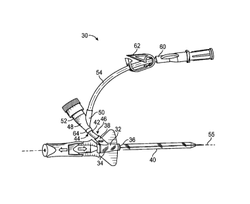
disadvantages or that operate only in environments such as those described
above. Rather, this
-1-
CA 03109296 2021-02-10
WO 2020/055587 PCT/US2019/048494
background is only provided to illustrate one example technology area where
some
implementations described herein may be practiced.
SUMMARY
[0005] The present disclosure relates generally to devices, systems, and
methods for facilitating
delivery of an instrument and/or fluid through a catheter, which may include a
peripheral
intravenous catheter (PIVC). The devices, systems, and methods of the present
disclosure may
also be used for blood withdrawal, according to some embodiments. In some
embodiments, the
instrument may include an additional catheter for fluid infusion or blood
draw, a guidewire, a
probe with a sensor, or a light tube for disinfection.
[0006] In some embodiments, a catheter assembly may include a catheter
adapter. In some
embodiments, the catheter adapter may include a proximal end, a distal end, a
lumen extending
through the proximal end and the distal end, and a side port. In some
embodiments, the catheter
assembly may include a catheter, such as, for example, a PIVC, which may
extend distally from
the catheter adapter.
[0007] In some embodiments, the catheter assembly may include a first
extension tube, which
may include a proximal end and a distal end. In some embodiments, the first
extension tube may
extend from the side port. In some embodiments, the catheter assembly may
include a first
connector coupled to the proximal end of the first extension tube. In some
embodiments, the first
connector may include a first port and/or a second port.
[0008] In some embodiments, the catheter assembly may include a second
extension tube,
which may include a proximal end and a distal end. In some embodiments, the
distal end of the
second extension tube may be coupled to the first port. In some embodiments,
the second extension
-2-
CA 03109296 2021-02-10
WO 2020/055587 PCT/US2019/048494
tube may be longer than the first extension tube. In some embodiments, the
catheter assembly may
include a second connector coupled to the proximal end of the second extension
tube. In some
embodiments, a clamp may be disposed on the first extension tube and/or the
second extension
tube.
[0009] In some embodiments, the first port may direct the second extension
tube distally. In
some embodiments, the first port may be disposed at an angle of less than 90
with respect to the
second port. In some embodiments, the second port may be aligned with a
longitudinal axis of the
first connector. In some embodiments, the first port may be disposed at an
angle between 45 and
90 with respect to the second port. In some embodiments, the first port may
be perpendicular to
the second port.
[0010] In some embodiments, the first connector may include a Y-shape or a
T-shape. In some
embodiments, the first port and the second port may form arms of the Y-shape
or the T-shape. In
some embodiments, the first connector may include a third port, which may form
a trunk of the Y-
shape or the T-shape. In some embodiments, the third port may extend
proximally, and the first
port and the second port may extend distally. In some embodiments, the first
port may direct the
second extension tube across a longitudinal axis of the catheter adapter.
[0011] In some embodiments, the first connector may not include any catch
points for fluid or
the instrument moving through the first connector in a distal direction to
enter the catheter adapter.
In some embodiments, the second connector may not include any catch points for
fluid or the
instrument moving through the second connector in the distal direction.
[0012] In some embodiments, the first connector may be selectively coupled
to the first
extension tube. Alternatively, in some embodiments, the first connector may be
permanently or
non-removably coupled to the first extension tube. In some embodiments, the
proximal end of the
-3-
CA 03109296 2021-02-10
WO 2020/055587 PCT/US2019/048494
first extension tube may be fixed within the first connector. In some
embodiments, the first
connector may be coupled to the proximal end of the first extension tube via a
snap fit.
[0013] In some embodiments, the catheter adapter may include multiple side
ports. In some
embodiments, the side port may be a first side port, and the catheter adapter
may include a second
side port. In some embodiments, the second side port may oppose the first side
port or extend from
a top of the catheter adapter. In some embodiments, the catheter assembly may
include one or
more of the following: a third extension tube, a third connector, a fourth
extension tube, and a
fourth connector.
[0014] In some embodiments, the third extension tube may include a proximal
end and a distal
end. In some embodiments, the third extension tube may extend from the second
side port. In some
embodiments, the third connector may be coupled to the proximal end of the
third extension tube.
In some embodiments, the third connector may include a third port and a fourth
port. In some
embodiments, the fourth extension tube may include a proximal end and a distal
end.
[0015] In some embodiments, the distal end of the fourth extension tube may
be coupled to the
third port of the third connector. In some embodiments, the fourth extension
tube may be longer
than the third extension tube. In some embodiments, the fourth connector may
be coupled to the
proximal end of the fourth extension tube. Thus, in some embodiments, the
catheter assembly may
include multiple extension sets.
[0016] In some embodiments, the third extension tube may extend from the
distal end of the
catheter adapter. In some embodiments, the distal end of the catheter adapter
may include a needle
port and/or a distal port from which the third extension tube extends. In some
embodiments, the
needle port and the distal port may be disposed vertically with respect to
each other. In some
-4-
CA 03109296 2021-02-10
WO 2020/055587 PCT/US2019/048494
embodiments, the needle port and the distal port may be disposed horizontally
with respect to each
other.
[0017] It is to be understood that both the foregoing general description
and the following
detailed description are exemplary and explanatory and are not restrictive of
the invention, as
claimed. It should be understood that the various embodiments are not limited
to the arrangements
and instrumentality shown in the drawings. It should also be understood that
the embodiments may
be combined, or that other embodiments may be utilized and that structural
changes, unless so
claimed, may be made without departing from the scope of the various
embodiments of the present
invention. The following detailed description is, therefore, not to be taken
in a limiting sense.
BRIEF DESCRIPTION OF THE SEVERAL VIEWS OF THE DRAWINGS
[0018] Example embodiments will be described and explained with additional
specificity and
detail through the use of the accompanying drawings in which:
[0019] Figure lA is an upper perspective view of an example prior art
catheter assembly;
[0020] Figure 1B is an upper perspective view of a prior art needle
assembly removed from the
prior art catheter assembly;
[0021] Figure 1C is a cross-sectional view of an example prior art
connector;
[0022] Figure 2A is an upper perspective view of a catheter assembly having
an example Y-
shaped connector, according to some embodiments;
[0023] Figure 2B is an upper perspective view of the catheter assembly of
Figure 2A having an
example T-shaped connector, according to some embodiments;
[0024] Figure 2C is an upper perspective view of the catheter assembly of
Figure 2A having an
example inverted Y-shaped connector, according to some embodiments;
-5-
CA 03109296 2021-02-10
WO 2020/055587 PCT/US2019/048494
[0025] Figure 3A is a cross-sectional view of an example connector,
according to some
embodiments;
[0026] Figure 3B is a cross-sectional view of another example connector,
according to some
embodiments;
[0027] Figure 4A is a cross-sectional view of an example Y-shaped
connector, according to
some embodiments;
[0028] Figure 4B is a cross-sectional view of an example T-shaped
connector, according to
some embodiments;
[0029] Figure 5 is an upper perspective view of another catheter assembly,
according to some
embodiments;
[0030] Figure 6A is an upper perspective view of another example catheter
adapter, according
to some embodiments;
[0031] Figure 6B is an upper perspective view of another example catheter
adapter, according
to some embodiments;
[0032] Figure 6C is a proximal end view of another example catheter
adapter, according to
some embodiments;
[0033] Figure 7A is a cross-sectional view of another example Y-shaped
connector, according
to some embodiments; and
[0034] Figure 7B is a cross-sectional view of the Y-shaped connector of
Figure 7A coupled to
an example extension tube via a snap fit.
DESCRIPTION OF EMBODIMENTS
-6-
CA 03109296 2021-02-10
WO 2020/055587 PCT/US2019/048494
[0035] Referring now to Figures 1A-1B, a prior art catheter assembly 10 is
illustrated. The prior
art catheter assembly 10 includes a catheter adapter 12 and a catheter 14
extending distally from
the catheter adapter 12. The prior art catheter assembly 10 also includes an
extension set, which
includes an extension tube 16 and a connector 17. The extension tube 16
extends from a side port
18 of the catheter adapter 12.
[0036] The prior art catheter assembly 10 further includes a needle hub 20
and an introducer
needle 22. When the needle hub 20 is coupled to the catheter adapter 12, the
introducer needle 22
extends through the catheter adapter 12 and the catheter 14 and beyond a
distal end of the catheter
14 to aid in insertion of the catheter 14 into vasculature of a patient.
[0037] As illustrated in Figure 1A, the extension tube 16 may curve around
a proximal end of
the catheter adapter 12 and/or the needle hub 20. In these and other
instances, the extension tube
16 may be in the way of a hand of a clinician as the clinician attempts to
insert the catheter 14 into
the vasculature of the patient. In some instances, the clinician may grip the
extension set in his or
her fingers to control the extension set during insertion of the catheter 14
into the vasculature of a
patient and/or to prevent the extension set from contacting an insertion site
of the catheter 14 once
the catheter 14 is inserted into the vasculature of the patient. Gripping the
extension set in such a
way during insertion of the catheter 14 may be complicated and require
physical coordination of
the clinician. Furthermore, in some instances, the extension tube 16 and/or
the connector 17 may
interfere with visualization of blood flashback by the clinician.
[0038] Referring now to Figure 1C, the connector 17 of the prior art
catheter assembly 10
includes one or more catch points 24, which may interfere with fluid or a
probe moving in a distal
direction through the connector 17. In some instances, the catch points 24 may
include surfaces
generally perpendicular to a longitudinal axis 26 or flow path of the
connector 17.
-7-
CA 03109296 2021-02-10
WO 2020/055587 PCT/US2019/048494
[0039] Referring now to Figures 2A-2B, in some embodiments, a catheter
assembly 30 may
include a catheter adapter 32, which may include a proximal end 34, a distal
end 36, a lumen
extending through the proximal end 34 and the distal end 36, and a side port
38. In some
embodiments, the catheter assembly 30 may include a catheter 40, such as, for
example, a PIVC,
extending distally from the catheter adapter 32. In some embodiments, the
catheter assembly 30
may include one or more elements of the prior art catheter assembly 10.
[0040] In some embodiments, the catheter assembly 30 may include a first
extension tube 42,
which may include a proximal end 44 and a distal end 46. In some embodiments,
the first extension
tube 42 may extend from the side port 38. In some embodiments, the catheter
assembly 30 may
include a first connector 48 coupled to the proximal end 44 of the first
extension tube 42. In some
embodiments, the first connector 48 may include a first port 50 and a second
port 52. In some
embodiments, the first connector 48 and/or the second port 52 may be disposed
in proximity to the
catheter adapter 32 and the catheter 40 to improve access for an instrument,
as well as to allow
higher viscosity or speed-critical fluid injections and improved flushing. In
some embodiments,
the instrument may include an additional catheter for fluid infusion or blood
draw, a guidewire, a
probe with a sensor, or a light tube for disinfection. In some embodiments, a
length of the first
extension tube 42 may be about 12 millimeters. In some embodiments, the length
of the first
extension tube 42 may be between about 11 and 13 millimeters. In some
embodiments, the length
of the first extension tube 42 may be between about 10 and 14 millimeters. In
some embodiments,
the length of the first extension tube 42 may be greater than 12 millimeters.
In some embodiments,
the length of the first extension tube 42 may be less than 12 millimeters. The
length of the first
extension tube 42 may vary, according to some embodiments.
-8-
CA 03109296 2021-02-10
WO 2020/055587 PCT/US2019/048494
[0041] In some embodiments, the catheter assembly 30 may include a second
extension tube
54, which may include a proximal end 56 and a distal end 58. In some
embodiments, the distal end
58 of the second extension tube 54 may be coupled to the first port 50. In
some embodiments, the
second extension tube 54 may be longer than the first extension tube 42. In
some embodiments,
the catheter assembly 30 may include a second connector 60, which may be
coupled to the
proximal end 56 of the second extension tube 54. In some embodiments, the
second port 52 may
be aligned with a longitudinal axis of the first connector 48. In some
embodiments, a clamp 62,
such as, for example, a slide clamp or a pinch clamp, may be disposed on the
first extension tube
42 and/or the second extension tube 54.
[0042] In some embodiments, the first port 50 may direct the second
extension tube 54 distally.
In some embodiments, the second extension tube 54 may be disposed away from an
area behind
the catheter adapter 32 and away from a longitudinal axis 55 of the catheter
adapter 32 to prevent
interference of the second extension tube 54 with the hand of the clinician as
the clinician grips
the catheter adapter 32 to insert the catheter 40 into the vasculature of the
patient.
[0043] In some embodiments, the first port 50 may be disposed at an angle
of less than 90
with respect to the second port 52, as illustrated, for example, in Figure 2A.
In further detail, in
some embodiments, the first port 50 may be disposed at an angle between 45
and 90 with respect
to the second port 52. In some embodiments, the first port 50 may be
perpendicular to the second
port 52, as illustrated, for example, in Figure 2B. In some embodiments, an
increased angle
between the first port 50 and the second port 52 may facilitate flushing of
the first port 50 without
flushing the second port 52. In some embodiments, a decreased angle between
the first port 50 and
the second port 52 may streamline fluid flow and instrument delivery into the
catheter 40. In some
-9-
CA 03109296 2021-02-10
WO 2020/055587 PCT/US2019/048494
embodiments, streamlined fluid flow may be beneficial for infusion of highly
viscous medications
or medications that are time-dependent.
[0044] In some embodiments, an extension set may include one or more of the
following: the
first extension tube 42, the first connector 48, the second extension tube 54,
and the second
connector 60. In some embodiments, the second extension tube 54 may be shorter
than the
extension tube 16 of the prior art, which may result in less movement of the
extension set and
fewer problems in controlling the extension set. However, in some embodiments,
the second
connector 60 may be disposed about a same distance from the insertion site as
the connector 17 of
the prior art, which may decrease interference with the catheter 40 at the
insertion site. In some
embodiments, a length of the second extension tube 54 may be less than about
5.350 inches. In
some embodiments, the length of the second extension tube 54 may be between
about 4 and 7
inches. In some embodiments, the length of the second extension tube 54 may be
less than about
6 inches or less than about 5.350 inches. The length of the second extension
tube 54 may vary,
according to some embodiments.
[0045] In some embodiments, the first connector 48 may include a Y-shape or
a T-shape. In
some embodiments, the first port 50 and the second port 52 may form arms of
the Y-shape. In
some embodiments, the first connector 48 may include a third port 64, which
may form a trunk of
the Y- shape.
[0046] In some embodiments, the first connector 48 may be selectively
coupled to the first
extension tube 42 and/or the second extension tube 54. In some embodiments,
the first connector
48 may be permanently or non-removably coupled to the first extension tube 42
and/or the second
extension tube 54. In some embodiments, the first port 50, the second port 52,
and the third port
64 of the first connector 48 may include any suitable type of coupling
mechanism.
-10-
CA 03109296 2021-02-10
WO 2020/055587 PCT/US2019/048494
[0047] In some embodiments, one or more of the first port 50, the second
port 52, and the third
port 64 may include a luer adapter, such as, for example, a slip or thread
male or female luer
adapter. In some embodiments, one or more of the first port 50, the second
port 52, and the third
port 64 may include a non-luer adapter. In some embodiments, one or more of
the first port 50, the
second port 52, and the third port 64 may include a blunt plastic cannula,
such as, for example, the
Baxter Interlink IV Access System. In some embodiments, one or more of the
first port 50, the
second port 52, and the third port 64 may include one or more barbs.
[0048] In some embodiments, one or more of the first port 50, the second
port 52, and the third
port 64 may be coupled to a needleless connector, such as, for example, the
Becton Dickinson
SMARTSITETm needle-free valve, or another suitable needleless connector. In
some
embodiments, one or more of the first port 50, the second port 52, and the
third port 64 may be
closed by an end cap. In some embodiments, one or more of the first port 50,
the second port 52,
and the third port 64 may include a vent plug. In some embodiments, one or
more of the first port
50, the second port 52, and the third port 64 may include one or more snap
elements, examples of
which are illustrated in Figure 7B.
[0049] In some embodiments, the distal end 58 of the second extension tube
54 may include a
particular connector having a corresponding coupling mechanism to the first
port 50. In some
embodiments, the distal end 58 of the second extension tube 54 may be fixed
inside the first
connector 48. In some embodiments, the proximal end 44 of the first extension
tube 42 may include
a particular connector having a corresponding coupling mechanism to the third
port 64 and/or the
first port 50. In some embodiments, the proximal end 44 of the first extension
tube 42 may be fixed
inside the first connector 48, as illustrated, for example, in Figures 2A-2C.
-11-
CA 03109296 2021-02-10
WO 2020/055587 PCT/US2019/048494
[0050] In some embodiments, the catheter assembly 30 may not include the
second extension
tube 54 and/or the second connector 60. In some embodiments, the first
connector 48 may only
include the first port 50 and the third port 64, which may be disposed
opposite the first port 50. In
some embodiments, the first connector 48 may include more than three ports.
[0051] In some embodiments, the second connector 60 may be selectively
coupled to the
second extension tube 54. Alternatively, in some embodiments, the second
connector 60 may be
permanently or non-removably coupled to the second extension tube 54. In some
embodiments,
the second connector 60 may include multiple ports, which may each include any
suitable type of
coupling mechanism. For example, the second connector 60 may include a
proximal port 68 and a
distal port 70. In some embodiments, the second connector 60 may include a Y-
shape or a T- shape.
[0052] In some embodiments, one or more of the multiple ports may include a
luer adapter,
such as, for example, a slip or thread male or female luer adapter. In some
embodiments, one or
more of the multiple ports may include a non-luer adapter. In some
embodiments, one or more of
the multiple ports may include a blunt plastic cannula, such as, for example,
the Baxter Interlink
IV Access System. In some embodiments, one or more of the multiple ports may
include one or
more barbs. In some embodiments, one or more of the multiple ports may be
coupled to a
needleless connector, such as, for example, the Becton Dickinson SMARTSITETm
needle-free
valve, or another suitable needleless connector. In some embodiments, one or
more of the one or
more of the multiple ports may be closed by an end cap. In some embodiments,
one or more of the
multiple ports may include a vent plug. In some embodiments, one or more of
the multiple ports
may include one or more snap elements, examples of which are illustrated in
Figure 7B. In some
embodiments, the proximal end 56 of the second extension tube 54 may include a
particular
connector having a corresponding coupling mechanism to the distal port 70. In
some embodiments,
-12-
CA 03109296 2021-02-10
WO 2020/055587 PCT/US2019/048494
the proximal end 56 of the second extension tube 54 may be fixed inside the
second connector 60,
as illustrated, for example, in Figures 2A-2C.
[0053] In some embodiments, the distal end 46 of the first extension tube
42 may be selectively
coupled to the catheter adapter 32. Alternatively, in some embodiments, the
distal end 46 of the
first extension tube 42 may be permanently or non-removably coupled to the
catheter adapter 32.
In some embodiments, the distal end 46 of the first extension tube 42 may be
fixed within the
catheter adapter 32, as illustrated, for example, in Figures 2A-2C. In some
embodiments, the side
port 38 of the catheter adapter 32 may include a luer adapter, such as, for
example, a slip or thread
male or female luer adapter. In some embodiments, the side port 38 of the
catheter adapter 32 may
include a non-luer adapter. In some embodiments, the side port 38 of the
catheter adapter 32 may
include one or more snap elements, examples of which are illustrated in Figure
7B. In some
embodiments, the distal end 46 of the first extension tube 42 may include a
particular connector
having a corresponding coupling mechanism to the side port 38.
[0054] In some embodiments, the first extension tube 42 may be coupled to
the catheter adapter
32 and/or the first connector 48 prior to or after insertion of the catheter
40 into the vasculature of
the patient and/or removal of an introducer needle from the catheter assembly
30. In some
embodiments, the second extension tube 54 may be coupled to the first
connector 48 prior to or
after insertion of the catheter 40 into the vasculature of the patient and/or
removal of an introducer
needle from the catheter assembly 30.
[0055] Referring now to Figure 2C, in some embodiments, the third port 64
may extend
proximally, and the first port 50 and the second port 52 may extend distally.
In some embodiments,
the first port 50 may direct the second extension tube 54 across the
longitudinal axis 55 of the
catheter adapter 32. In some embodiments, the second port 52 may be coupled to
the proximal end
-13-
CA 03109296 2021-02-10
WO 2020/055587 PCT/US2019/048494
44 of the first extension tube 42. In some embodiments, the first connector 48
and/or the second
connector 60 may be transparent, which may facilitate access, flow, flush, and
manufacturing
visibility.
[0056] Referring now to Figure 3A, an example connector 72 is illustrated.
In some
embodiments, the connector 72 may include or correspond to the first connector
48 and/or the
second connector 60 discussed with respect to Figures 2A-2B. In some
embodiments, a proximal
end of the extension tube 74 may be fixed within a distal port 76 of the
connector 72. In some
embodiments, the proximal end of the extension tube 74 may include or
correspond to the proximal
end 44 of the first extension tube 42 and/or the proximal end 56 of the second
extension tube 54.
In some embodiments, the distal port 76 may include or correspond to the
distal port 70 of the
second connector 60 and/or the third port 64 of the first connector 48. In
some embodiments, a
proximal port 78 of the connector 72 may include or correspond to the proximal
port 68 of the
second connector 60 and/or the second port 52 of the first connector 48.
[0057] In some embodiments, the connector 72 may not include any catch
points for fluid or
the instrument 80 moving through the connector 72 in the distal direction. For
example, the catch
points 24, illustrated in Figure 1C, may be removed. In some embodiments, an
entirety of a lumen
82 of the connector 72 tapers inwardly in the distal direction or expands to a
larger diameter in the
distal direction. In some embodiments, all portions of an inner surface of the
connector 72 forming
the lumen 82 that are perpendicular to a longitudinal axis of the connector 72
may be removed. In
some embodiments, the connector 72 may or may not include a wedge to eliminate
the catch points.
[0058] Referring now to Figure 3B, in some embodiments, the connector 72
may be shortened
to facilitate rapid infusion of medications and instrument access. In some
embodiments, a length
-14-
CA 03109296 2021-02-10
WO 2020/055587 PCT/US2019/048494
of the connector 72 may be between about 0.5 and 0.6 inches. In some
embodiments, the length of
the connector 72 may be about 0.57 inches.
[0059] Referring now to Figure 4A, in some embodiments, another connector
88 is illustrated,
according to some embodiments. In some embodiments, the connector 88 may
include or
correspond to the first connector 48 and/or the second connector 60 discussed
with respect to
Figures 2A-2B. In some embodiments, the connector 88 may not include any catch
points for fluid
or the instrument 80 (illustrated, for example, in Figures 3A-3B) moving
through the connector 88
in the distal direction to enter the catheter adapter 32. In some embodiments,
catch points similar
to the catch points 24, illustrated in Figure 1C, for example, may be removed
from a fluid pathway
between a proximal port and a distal port, or between the second port 52 and
the third port 64 of
Figures 2A-2B, for example. In some embodiments, the connector 88 may or may
not include a
wedge to eliminate the catch points.
[0060] Referring now to Figure 4B, a connector 90 may include or correspond
to the first
connector 48 and/or the second connector 60 discussed with respect to Figures
2A-2B. In some
embodiments, the connector 90 may not include any catch points for fluid or
the instrument 80
moving through the connector 90 in the distal direction to enter the catheter
adapter 32. In some
embodiments, catch points similar to the catch points 24, illustrated in
Figure 1C, for example,
may be removed from a fluid pathway between a proximal port and a distal port,
or between the
second port 52 and the third port 64 of Figures 2A-2B, for example. In some
embodiments, the
connector 90 may or may not include a wedge to eliminate the catch points.
[0061] Referring now to Figure 5, in some embodiments, a catheter assembly
92 may include
two or more extension tubes 94 extending from the side port 38. In some
embodiments, a single
extension tube may bifurcate or split into the extension tubes 94. In some
embodiments, the
-15-
CA 03109296 2021-02-10
WO 2020/055587 PCT/US2019/048494
bifurcation or splitting may occur within the side port 38 or outside of the
side port 38. In some
embodiments, the catheter assembly 92 may include or correspond to the prior
art catheter
assembly 10 discussed with respect to Figures 2A-2C. In further detail, in
some embodiments, the
catheter assembly 92 may include one or more features of the prior art
catheter assembly 10
discussed with respect to Figures 2A-2C, such as, for example, the first
connector 48 and/or the
second connector 60. In some embodiments, one or more of the extension tubes
94 may include
or correspond to the first extension tube 42 and/or the catheter assembly 92
may include multiple
extension sets.
[0062] Referring now to Figure 6A-6B, in some embodiments, the catheter
adapter 32 may
include various configurations. In some embodiments, the catheter adapter 32
may include
multiple side ports 38. As illustrated in Figure 6A, in some embodiments, a
side port 38a may
extend from a side of the catheter adapter 32 and/or another side port 38b may
extend from a top
of the catheter adapter 32. Additionally or alternatively, in some
embodiments, another side port
38c may oppose the side port 38a. In some embodiments, the extension tubes 94
of Figure 5 may
extend from any of the side ports 18 of Figures 6A-6B. In some embodiments,
all or a portion of
the extension set of Figures 2A-2C may extend from any of the side ports 38 of
Figures 6A-6B. In
some embodiments, the first extension tube 42 described with respect to
Figures 2A-2C may
extend from any of the side ports 18 of Figures 6A-6B.
[0063] Referring now to Figure 6C, in some embodiments, a distal end 96 of
the catheter
adapter 12 may include a needle port 98 and/or a distal port 100 from which an
extension tube,
such as, for example, the first extension tube 42 of Figures 2A-2C may extend.
In some
embodiments, the extension tubes 94 of Figure 5 may extend from the distal
port 100. In some
embodiments, the needle port 98 and the distal port 100 may be disposed
vertically with respect to
-16-
CA 03109296 2021-02-10
WO 2020/055587 PCT/US2019/048494
each other, as illustrated, for example, in Figure 6C. In some embodiments,
positioning of the
distal port 100 towards a top of the catheter may facilitate entry of the
instrument in to the catheter
40 and/or the vasculature of the patient at a downward angle. In some
embodiments, the needle
port 98 and the distal port 100 may be disposed horizontally with respect to
each other.
[0064] Referring now to Figures 7A-7B, in some embodiments, one or more
components of the
catheter assembly 30 described with respect to Figures 2A-2C may be coupled
together via a snap
fit. For example, as illustrated in Figures 7A-7B, a proximal end of the first
extension tube 42 may
include a snap mechanism 102 having snap elements 104 configured to move past
corresponding
snap elements 106 of the first connector 48 and engage the first connector 48
and the first extension
tube 42 together in a snap fit. In some embodiments, a blunt cannula 108 may
penetrate a blood
control valve 110 of the first connector 48. It is contemplated that the first
connector may include
the blunt cannula 108.
[0065] All examples and conditional language recited herein are intended
for pedagogical
objects to aid the reader in understanding the invention and the concepts
contributed by the
inventor to furthering the art, and are to be construed as being without
limitation to such
specifically recited examples and conditions. Although embodiments of the
present inventions
have been described in detail, it should be understood that the various
changes, substitutions, and
alterations could be made hereto without departing from the spirit and scope
of the invention.
-17-