Note: Descriptions are shown in the official language in which they were submitted.
MODULAR POWER BASES FOR WHEELCHAIRS
CROSS-REFERENCE TO RELATED APPLICATIONS
[0001] This application claims priority to U.S. Patent Application
No. 16/133,198 filed on
September 17, 2018.
TECHNICAL FIELD
[0002] The present specification generally relates to systems for
powering wheelchairs
and, more specifically, to modular power bases for wheelchairs.
BACKGROUND
[0003] Current wheelchairs may be limited to planar travel. If a wheelchair
user wants to
travel vertically, they must find a ramp because the wheelchair limits the
user from overcoming
discrete vertical obstacles, such as steps. Additionally, current wheelchairs
cannot raise and lower
a seat based on wheel movement of the chair. Moreover, the application of
current wheelchair
wheels does not extend beyond the scope of the chair itself meaning that a
user gets no benefit
from wheelchair wheels unless he or she is actually using the wheelchair.
Accordingly, modular
power bases for wheelchairs are desirable.
SUMMARY
[0004] In one embodiment, a modular power base for a wheelchair
includes a leg module.
The leg module includes an upper leg portion comprising a distal end and a
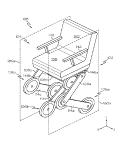
proximal end. The
proximal end is configured to be detachably and rotatably coupled to a seat
portion of the
wheelchair. The leg module also includes a lower leg portion having a first
end and a second end,
the first end of the lower leg portion being rotatably coupled to the distal
end of the upper leg
portion. The leg module also includes a first wheel rotatably coupled to the
distal end of the upper
leg portion and to the first end of the lower leg portion and a second wheel
rotatably coupled to
the second end of the lower leg portion.
1
Date Recue/Date Received 2022-02-01
[0005] In another embodiment, a wheelchair assembly includes a seat
portion and a leg
module detachably coupled to the seat portion. The leg module includes an
upper leg portion
comprising a distal end and a proximal end. The proximal end is configured to
be detachably and
rotatably couple to the seat portion. The leg module also includes a lower leg
portion having a
first end and a second end, the first end of the lower leg portion being
rotatably coupled to the
distal end of the upper leg portion. The leg module also includes a first
wheel rotatably coupled
to the distal end of the upper leg portion and to the first end of the lower
leg portion and a second
wheel rotatably coupled to the second end of the lower leg portion.
[0006] In yet another embodiment, a wheelchair assembly includes a
seat portion, a first
leg module detachably coupled to the seat portion, and a second leg module
detachably coupled to
the seat portion. Each of the first leg module and the second leg module
includes an upper leg
portion comprising a distal end and a proximal end. The proximal end is
configured to detachably
and rotatably couple to the seat portion. Each of the first leg module and the
second leg module
includes a lower leg portion having a first end and a second end, the first
end of the lower leg
portion is rotatably coupled to the distal end of the upper leg portion. A
first wheel is rotatably
coupled to the distal end of the upper leg portion and to the first end of the
lower leg portion. A
second wheel is rotatably coupled to the second end of the lower leg portion.
[0007] These and additional features provided by the embodiments
described herein will
be more fully understood in view of the following detailed description, in
conjunction with the
drawings.
BRIEF DESCRIPTION OF THE DRAWINGS
[0008] The embodiments set forth in the drawings are illustrative
and exemplary in nature
and not intended to limit the subject matter defined by the claims. The
following detailed
description of the illustrative embodiments can be understood when read in
conjunction with the
following drawings, where like structure is indicated with like reference
numerals and in which:
[0009] FIG. 1 depicts a schematic illustration of a wheelchair
assembly including a
modular power base and a leg module, according to one or more embodiments
shown and
described herein;
2
Date Recue/Date Received 2022-02-01
[0010] FIG. 2 depicts the wheelchair assembly including multiple
leg modules, according
to one or more embodiments shown and described herein;
[0011] FIG. 3 depicts a schematic diagram of one or more electro-
mechanical components
of a modular power base, according to one or more embodiments shown and
described herein;
[0012] FIG. 4A depicts the wheelchair assembly approaching an obstacle,
according to one
or more embodiments shown and described herein;
[0013] FIG. 4B depicts the wheelchair assembly climbing the
obstacle of FIG. 4A,
according to one or more embodiments shown and described herein;
[0014] FIG. 4C depicts the wheelchair assembly of FIG. 4A with a
middle leg module on
an obstacle, according to one or more embodiments shown and described herein;
[0015] FIG. 5 depicts a standard wheelchair adapted for use with a
leg module, according
to one or more embodiments shown and described herein;
[0016] FIG. 6 depicts a leg module adapted for use as a scooter,
according to one or more
embodiments shown and described herein;
[0017] FIG. 7 depicts a leg module adapted for use as an exoskeletal
adaptation of the leg
module of the wheelchair assembly, according to one or more embodiments shown
and described
herein; and
[0018] FIG. 8A depicts the wheelchair assembly in a retracted
configuration, according to
one or more embodiments shown and described herein;
[0019] FIG. 8B depicts the wheelchair assembly in a seating-assist
configuration,
according to one or more embodiments shown and described herein;
[0020] FIG. 8C depicts the wheelchair assembly in a standing
configuration with at least
one auxiliary brace extending from the wheelchair assembly, according to one
or more
embodiments shown and described herein;
3
Date Recue/Date Received 2022-02-01
[0021] FIG. 9A depicts the wheelchair assembly in a bipedal
configuration, according to
one or more embodiments shown and described herein;
[0022] FIG. 9B depicts the wheelchair assembly in a bipedal
configuration with one leg
module extended over an obstacle, according to one or more embodiments shown
and described
herein;
[0023] FIG. 10A depicts the wheelchair assembly in a retracted
configuration, according
to one or more embodiments shown and described herein;
[0024] FIG. 10B depicts the wheelchair assembly approaching an
obstacle with a middle
leg module retracted upward, according to one or more embodiments shown and
described herein;
[0025] FIG. 10C depicts the wheelchair assembly climbing an obstacle,
according to one
or more embodiments shown and described herein; and
[0026] FIG. 11 depicts the wheelchair assembly of FIG. 4A bending
such that a user can
conveniently enter or exit a seat portion of the wheelchair assembly,
according to one or more
embodiments shown and described herein.
DETAILED DESCRIPTION
[0027] Wheelchair assemblies may include a modular power base
including at least one
leg module supporting and powering the wheelchair assembly. The leg module may
be selectively
attachable to the wheelchair assembly and adaptable for use in one or more
systems and/or
assemblies external to the wheelchair. The leg module may include at least one
driven wheel and
an electric motor configured to drive the driven wheel. The driven wheel(s)
may be used to power
the wheelchair assembly and may also be used to power the systems and/or
assemblies external to
the wheelchair assembly. One or more portions of the leg module may articulate
with respect to a
seat portion of the wheelchair assembly to balance and position the seat
and/or to surmount
environmental obstacles in a path of the wheelchair assembly. The articulable
portions of the leg
module may be articulated by one or more actuators. Leg modules as described
herein may
4
Date Recue/Date Received 2022-02-01
enhance the versatility and usability of wheelchair assemblies. For example,
they may enable the
wheelchair assembly to overcome obstacles in its path. Additionally, leg
modules may have
separate and external applications as systems and/or components that increase
and/or enhance a
user's mobility options.
[0028] Referring now to FIG. 1, an illustrative embodiment of a wheelchair
assembly 100
including a modular power base 102 that may be used to support a seat portion
104 is shown. The
wheelchair assembly 100 includes at least one leg module 106 including an
upper leg portion 108
including a distal end 110 and a proximal end 112. The upper leg portion 108
may be rotatably
coupled to a lower leg portion 114 and define a knee joint 116. The lower leg
portion 114 includes
a first end 118 and a second end 120. The leg module 106 may further include a
first wheel 122
and a second wheel 124. The wheelchair assembly 100 may further include a seat
138, a backrest
140, and one or more armrests 142. FIG. 2 shows a wheelchair assembly 105 with
three leg
modules 106a, 106b, 106c. Each of the leg modules 106a, 106b, 106c includes
the same
components as the leg module 106 depicted in FIG. 1. The components of the leg
modules 106a,
106b, 106c corresponding to the components of the leg module 106 are numbered
the same with
a, b, and c letters indicating the distinct components of the three separate
leg modules 106a, 106b,
106c. For the purposes of the description, reference will be made to the leg
module 106 in FIG. 1
without reference to any particular one of the multiple leg modules 106a,
106b, 106c unless
specifically stated. Although the particular leg modules 106a, 106b, and 106c
of FIG. 2 may be
distinctly arranged, it is to be understood that each of the components of the
leg module 106
described with respect to FIG. 1 are included in each of the leg modules 106a,
106b, and 106c of
FIG. 2 unless specifically described otherwise.
[0029] Referring again to FIG. 1, the upper leg portion 108
generally includes an elongate
bar extending between the distal end 110 and the proximal end 112. The upper
leg portion 108
may include a distal aperture 126 positioned at the distal end 110 and a
proximal aperture 128
positioned at the proximal end 112. The proximal end 112 is configured to be
detachably and
rotatably coupled to the seat portion 104. It is contemplated that the distal
aperture 126 and the
proximal aperture 128 may be placed closer or farther apart from one another
in various
embodiments. When assembled to the wheelchair assembly 100, the upper leg
portion 108 may
be rotatably coupled to the seat portion 104 at the proximal aperture 128 to
form a hip joint 130.
5
Date Recue/Date Received 2022-02-01
In some embodiments, the hip joint 130 may be formed between the proximal
aperture 128 of the
upper leg portion 108 and a frame aperture 144 of a frame member 146 that may
be coupled to a
bottom surface 148 of the seat portion 104 when the wheelchair assembly 100 is
assembled.
[0030] As will be described in greater detail herein, the frame
member 146 may be any
structure configured to provide a location to couple the upper leg portion 108
to the seat portion
104. For example, and as shown, the frame member 146 may have the frame
aperture 144, wherein
a fastener may be passed through both the upper leg portion 108 and the frame
member 146 to
secure the frame member 146 and the upper leg portion 108 to one another. For
example, and as
described above, the frame member 146 may be coupled to the bottom surface 148
of the seat
portion 104. Briefly referring to FIG. 4A, the wheelchair assembly 100 may
include multiple frame
members 146, for example, some embodiments may include a first frame member
146a and a
second frame member 146b. That is, each leg module 106 may have a dedicated
frame member
146 through which the leg module 106 may be coupled to the seat portion 104 of
the wheelchair
assembly 100. However, it is contemplated that a single frame member 146 may
be used that may
be similar or distinct from the frame member 146. Referring back to FIG. 1,
the frame member
146 may be mechanically coupled to a bottom surface 148 of the seat portion
104 (e.g., through
fasteners, adhesives, welding, brazing, and the like). The various frame
members may be
positioned on the bottom surface 148 of the seat portion 104 such that the leg
modules 106 do not
extend beyond and increase a width of the wheelchair assembly 100 defined by
the seat portion
104.
[0031] Still referring to FIG. 1, the upper leg portion 108 may be
rotatably coupled to the
lower leg portion 114 to define the knee joint 116. The lower leg portion 114
may generally
include an elongate bar extending between the first end 118 and the second end
120. The lower
leg portion 114 may include a first aperture 132 to facilitate coupling of the
upper leg portion 108
to the lower leg portion 114. For example, the distal aperture 126 of the
upper leg portion 108 and
the first aperture 132 of the lower leg portion 114 may be aligned and a
fastener may be passed
through to rotatably couple the upper leg portion 108 to the lower leg portion
114 at the knee joint
116. The lower leg portion 114 may further include a second aperture 134. In
some embodiments,
the first aperture 132 and the second aperture 134 may be located at the first
end 118 and the
second end 120 respectively and as illustrated in the figures, but embodiments
are not limited to
6
Date Recue/Date Received 2022-02-01
this arrangement. It is contemplated that the first aperture 132 and the
second aperture 134 may
be located at any position along the length of the lower leg portion 114. In
some embodiments, the
upper leg portion 108 is coupled to the lower leg portion 114 at the first end
118, but it is
contemplated that the upper leg portion 108 may couple to the lower leg
portion 114 at any position
along the length of the lower leg portion 114. Accordingly, the knee joint 116
may be positioned
anywhere along the length of the lower leg portion 114 and the upper leg
portion 108.
[0032] In some embodiments, the first wheel 122 is coupled to the
lower leg portion 114
and to the upper leg portion 108 at the knee joint 116. In some embodiments,
the second aperture
134 is located at the second end 120 and the second wheel 124 is coupled to
the lower leg portion
114 at the second end 120, but it is contemplated that the second wheel 124
and/or the second
aperture 134 may be located at any point along the length of the lower leg
portion 114.
[0033] In the particular embodiment shown in FIG. 1, the upper leg
portion 108 and the
lower leg portion 114 are equal lengths. However, embodiments are contemplated
in which the
upper leg portion 108 and the lower leg portion 114 are different lengths. For
example,
embodiments are contemplated in which the upper leg portion 108 is longer than
the lower leg
portion 114 or the lower leg portion 114 is longer than the upper leg portion
108. Additionally,
embodiments in which the lengths of the lower leg portions 114 and/or upper
leg portions 108 of
different leg modules 106 are different relative to one another are
contemplated. With brief
reference to FIG. 2, it is contemplated that the left upper leg portion 108a
may be a different length
than the middle upper leg portion 108b, which may be a different length than
the right upper leg
portion 108c. Further, it is contemplated that the left lower leg portion 114a
may be a different
length than the middle lower leg portion 114b, which may be a different length
than the right lower
leg portion 114c.
[0034] In the particular embodiment shown in FIG. 1, the motion of
the upper leg portion
108 and the lower leg portion 114 may be in the same plane or in parallel
planes. However,
embodiments are contemplated in which the motion of the upper leg portion 108
and the lower leg
portion 114 are in non-parallel planes. For example, in some embodiments, the
upper leg portion
108 and/or the lower leg portion 114 can rotate in more than one radial
direction at the hip joint
130 and/or the knee joint 116 (e.g., a ball-and-socket joint type at the hip
joint 130 and/or knee
7
Date Recue/Date Received 2022-02-01
joint 116). Briefly referring to the particular illustrated embodiment of FIG.
2, the leg modules
106a, 106b, 106c do not extend out from beneath the wheelchair assembly 100
(i.e., they do not
extend outward of the parallel planes 180a and 180b), but embodiments are not
limited to this
configuration.
[0035] Referring to FIGS. 1 and 3, the wheelchair assembly 100 may include
an upper leg
actuator 224 that may be configured to articulate the upper leg portion 108
with respect to the seat
portion 104. In some embodiments, the upper leg actuator 224 is mechanically
coupled to one or
more of the upper leg portion 108, the frame member 146, and the seat portion
104. The upper leg
actuator 224 (described in greater detail herein with respect to the schematic
shown in FIG. 3) may
be a servomotor, a linear actuator, a pneumatic or hydraulic actuator, a
torsional motor, or other
type of actuator configured to actuate the upper leg portion 108.
[0036] Still referring to FIGS. 1 and 3, the wheelchair assembly
100 may further include a
lower leg actuator 226 configured to articulate the lower leg portion 114 with
respect to the upper
leg portion 108. In some embodiments, the lower leg actuator 226 is
mechanically coupled to one
or more of the upper leg portion 108 and the lower leg portion 114. The lower
leg actuator 226
(described in greater detail herein with respect to the schematic shown in
FIG. 3) may be a
servomotor, a linear actuator, a pneumatic or hydraulic actuator, a torsional
motor, or other type
of actuator configured to actuate the lower leg portion 114 with respect to
the upper leg portion
108.
[0037] Still referring to FIGS. 1 and 3, one or more of the first wheel 122
and the second
wheel 124 may be driven. One or more drive motors 212 and gear boxes 214 may
be used to
power the first wheel 122 and/or the second wheel 124. The drive motors 212
and gear boxes 214
may form a drive assembly 202 and the drive assembly 202 may be
communicatively coupled to
a control and power system 200 including one or more motor controllers and may
be electrically
coupled to a power assembly 206 including a battery for supplying electrical
power to the motors.
The drive assembly 202, control unit 204, and power assembly 206 are described
in greater detail
herein. In some embodiments, one or more of the first wheel 122 and the second
wheel 124 may
be an omni-directional wheel as described in US Patent Number 8,418,705
"Robotic Cane
Devices,".
8
Date Recue/Date Received 2022-02-01
[0038] Still referring to FIGS. 1 and 3, the modular power base 102
for the wheelchair
assembly 100 may include a control and power system 200. In some embodiments,
each leg
module 106 may include its own separate control and power system 200, but it
is to be understood
that one or more of the leg modules 106 of the modular power base 102 may
include a different
system that controls and powers the leg module 106 or may not include any
system for controlling
and/or powering the leg module 106 (e.g., in leg modules 106 that are slaves
of a master leg
module, a master wheelchair controller, etc.).
[0039] Referring to FIG. 3, the control and power system 200 may
generally include a
drive assembly 202, a control unit 204, a power assembly 206, a sensor unit
216 for sensing one
or more external objects and/or a posture of one or more components, an
actuator control unit 218,
and network interface hardware 220 that are communicatively coupled to a
communication path
201. The control and power system 200 may further include a user input module
222 for inputting
one or more user inputs to affect the control and power system 200. The
control unit 204 may
include a processor 208 and a memory module 210 that stores a non-transitory
processor readable
instruction set that includes one or more instructions as will be described in
greater detail herein.
The drive assembly 202 may include one or more drive motors 212, and gear
boxes 214. The
network interface hardware 220 may communicatively couple the control and
power system 200
to external systems.
[0040] The communication path 201 may be formed from any medium
that is capable of
transmitting a signal such as, for example, conductive wires, conductive
traces, optical
waveguides, or the like. The communication path 201 may also refer to the
expanse in which
electromagnetic radiation and their corresponding electromagnetic waves
traverses. Moreover,
the communication path 201 may be formed from a combination of mediums capable
of
transmitting signals. In one embodiment, the communication path 201 includes a
combination of
conductive traces, conductive wires, connectors, and buses that cooperate to
permit the
transmission of electrical data signals to components such as processors,
memories, sensors, input
devices, output devices, and communication devices. Accordingly, the
communication path 201
may include a bus. Additionally, it is noted that the term "signal" means a
waveform (e.g.,
electrical, optical, magnetic, mechanical or electromagnetic), such as DC, AC,
sinusoidal-wave,
triangular-wave, square-wave, vibration, and the like, capable of traveling
through a medium. The
communication path 201 communicatively couples the various components of the
control and
9
Date Recue/Date Received 2022-02-01
power system 200. As used herein, the term "communicatively coupled" means
that coupled
components are capable of exchanging signals with one another such as, for
example, electrical
signals via conductive medium, electromagnetic signals via air, optical
signals via optical
waveguides, and the like.
[0041] In some embodiments, the drive assembly 202 may be electrically and
communicatively coupled to the communication path 201. The drive assembly 202
may include
the drive motor 212. The drive motor 212 may be any typical electronic motor,
for example, a six-
pole electric motor. The drive motor 212 may be controlled by a motor
controller that selectively
applies power to the drive motor 212. Briefly referring to FIGS. 2 and 3, each
of the first wheel
122 and the second wheel 124 may be driven by a separate drive motor, such as
the drive motor
212. Additionally, the gear boxes 214 may include one or more gears and may
translate the
rotational motion of the drive motor 212 to rotational motion of the first
wheel 122 and/or the
second wheel 124. The first wheel 122 and the second wheel 124 may each be
configured to
actuate separately of one another, enabling the first wheel 122 and the second
wheel 124 to move
the leg module 106 such that the leg module 106 can move up and down vertical
obstacles as will
be described in greater detail herein.
[0042] Referring to FIG. 3, the control unit 204 may be any device
or combination of
components including one or more processors 208 and memory modules 210 that
contain one or
more non-transitory processor-readable instruction sets. Accordingly, the
control unit 204 may
include an electric controller, an integrated circuit, a microchip, a
computer, or any other
computing device. While the control unit 204 depicted in FIG. 3 includes a
single processor 208,
other embodiments may include more than one processor.
[0043] The memory module 210 of the control unit 204 may include
RAM, ROM, flash
memories, hard drives, or any non-transitory memory device capable of storing
processor-readable
instructions such that the processor-readable instructions can be accessed and
executed. The
processor-readable instruction set may include logic or algorithm(s) written
in any programming
language of any generation (e.g., 1GL, 2GL, 3GL, 4GL, or 5GL) such as, for
example, machine
language that may be directly executed by the control unit 204, or assembly
language, object-
oriented programming (00P), scripting languages, microcode, etc., that may be
compiled or
assembled into machine readable instructions and stored in the memory module
210.
Date Recue/Date Received 2022-02-01
Alternatively, the machine-readable instruction set may be written in a
hardware description
language (HDL), such as logic implemented via either a field-programmable gate
array (FPGA)
configuration or an application-specific integrated circuit (ASIC), or their
equivalents.
Accordingly, the functionality described herein may be implemented in any
conventional
computer programming language, as pre-programmed hardware elements, or as a
combination of
hardware and software components. While the embodiment depicted in FIG. 3
includes a control
unit 204 with a single memory module 210, other embodiments may include more
than one
memory module.
[0044] Embodiments of the control and power system 200 may include
the power
assembly 206. The power assembly 206 may include a DC power source for
supplying electric
power to the control and power system 200 and its components. For example, the
power assembly
206 may supply power to the modular power base 102 of FIG. 1. Still referring
to FIG. 3, the
power assembly 206 may include one or more devices configured to plug the
power assembly 206
into a standard 110 V AC wall socket, for example, a wall socket in a typical
American home in
order to charge the power assembly 206. In some embodiments, the power
assembly 206 may be
configured with one or more batteries, such as a Li-ion battery, such that
when the power assembly
206 is plugged into a wall, the power assembly 206 can store power to provide
to one or more
components of the control and power system 200. Briefly referring to both
FIGS. 1 and 3, the
power assembly 206 may electrically couple with a battery bank that may be in
the seat portion
104 or another portion of the wheelchair assembly 100. The volume of the seat
portion 104 may
be greater than a volume of the leg module 106, and this added volume may be
utilized to house a
battery with a greater capacity than can fit in the leg module 106 or other
smaller portions of the
wheelchair assembly 100. In some embodiments, the leg module 106 may include
its own battery
that is used when the leg module 106 is disconnected from the wheelchair
assembly 100.
[0045] Referring again to FIG. 3, the network interface hardware 220 may be
any device
capable of transmitting and/or receiving data via a network. Accordingly,
network interface
hardware 220 can include a communication transceiver for transmitting and/or
receiving any
wireless communication. For example, the network interface hardware 220 may
include an
antenna, Wi-Fi card, WiMax card, mobile communications hardware, near-field
communication
hardware, satellite communication hardware and/or any wireless hardware for
communicating
11
Date Recue/Date Received 2022-02-01
with other networks and/or devices (e.g., hardware for communicating via a
Bluetooth or 5G
connection). In one embodiment, network interface hardware 220 includes
hardware configured
to operate in accordance with the Bluetooth wireless communication protocol.
In another
embodiment, network interface hardware 220 may include a Bluetooth
send/receive module for
transmitting and receiving Bluetooth communications to/from a network. In some
embodiments,
the network interface hardware 220 may allow the various components of the
wheelchair assembly
100 to communicate with one another and/or with external devices. For example,
various
electronic components of the leg modules 106 may be communicatively coupled to
the control and
power system 200 over the communication path 201.
[0046] The sensor unit 216 may include one or more sensors configured to
output a signal
indicative of at least one of an environmental condition or a posture of each
of the leg modules
106. In some embodiments, an environmental condition may include the presence
of an obstacle
(e.g., stairs, an uneven surface, etc. in the path of the leg module 106). The
sensor unit 216 may
generate a signal based on the presence of an obstacle that causes the wheels
and/or the leg portions
to actuate (i.e., move) in response to the signal. Accordingly, the sensors
may include one or more
proximity sensors, touch sensors, cameras, and/other sensors for sensing the
environment. In one
particular embodiment, the sensors include a proximity sensor that is
configured to emit a signal
in the vicinity of the control and power system 200 and receive a signal that
reflects from an
environmental obstacle. For example, the sensors may include a LIDAR, LADAR,
radar, sonar
sensor, and/or laser scanners. In some embodiments, the sensor unit 216 may
include a sensor that
is configured to determine how fast an external object is approaching based on
a change in relative
speed between the external object and the wheelchair assembly 100. For
example, the sensor unit
216 may include a Doppler effect sensor. Additionally, the sensor unit 216 may
include one or
more gyroscopes, accelerometers, angle sensors, torque sensors, and/or other
sensors for tracking
the posture and motion of the wheelchair assembly 100. The sensor unit 216 may
be configured
to detect an orientation of the wheelchair assembly 100 and/or one or more
components thereof.
For example, the sensor unit 216 may be configured to sense a level condition
of the seat portion
104 in order to maintain the seat portion 104 level with respect to ground to
keep an occupant of
the seat portion 104 balanced.
12
Date Recue/Date Received 2022-02-01
[0047] The actuator control unit 218 may control one or more
actuators. For example,
with reference to FIGS. 2 and 3, the actuator control unit 218 may control an
actuator for actuating
the upper leg portion 108 to rotate the upper leg portion 108 with respect to
the seat portion 104.
The actuator control unit 218 may also control an actuator for actuating the
lower leg portion 114
to rotate with respect to the upper leg portion 108. The upper leg portion 108
and the lower leg
portion 114 may be actuated independently of one another. The upper leg
portion 108 and the
lower leg portion 114 may be actuated, for example, to overcome obstacles, to
balance the seat
portion 104, or for other reasons as will be described in greater detail
herein.
[0048] Communicatively coupled to the control and power system 200
over the
communication path 201 is the user input module 222. The user input module 222
may include
tactile input hardware (e.g., joystick, knob, lever, button, etc.) that allows
an operator to input
commands into the control and power system 200 to operate one or more of the
actuators and/or
motors that control the various leg modules and wheels of the wheelchair
assembly 100. In some
embodiments, a joystick or other type of mechanical input device is
communicatively coupled to
the control and power system 200 such that when the joystick or other input
device is activated
(i.e., touched, moved, etc.), the one or more processors 208 of the control
unit 204 execute logic
stored on the one or more memory modules 210 to activate the actuators and/or
motors.
[0049] The control and power system 200 may be communicatively
coupled to one or more
actuators for actuating the various components of the leg modules 106 over the
communication
path 201. For example, the control and power system 200 may be communicatively
coupled to an
upper leg actuator 224 and a lower leg actuator 226. One or more of the upper
leg actuator 224
and the lower leg actuator 226 may be configured to move one or more of the
lower leg portion
114 and the upper leg portion 108. For example, the upper leg actuator 224 may
be configured to
move the upper leg portion 108 about the hip joint 130 with respect to the
seat portion 104. The
lower leg actuator 226 may be configured to move the lower leg portion 114
about the knee joint
116 with respect to the upper leg portion 108. The upper leg actuator 224 and
the lower leg actuator
226 may be communicatively coupled to the one or more processors 208, such
that the one or more
processors 208 execute logic stored in the one or more memory modules 210 to
move the leg
module 106 as described above. The upper leg actuator 224 and/or the lower leg
actuator 226 may
13
Date Recue/Date Received 2022-02-01
be DC motor, a stepper motor, or any other actuator as described herein that
is capable of moving
the upper leg portion 108 and/or the lower leg portion 114.
[0050] The wheelchair assembly 105 of FIG. 2 and the wheelchair
assembly 150 of FIGS.
4A-4C may include a similarly configured control and power system 200.
[0051] FIGS. 4A and 4B show a wheelchair assembly 150 approaching an
obstacle 400
and FIG. 4C shows the wheelchair assembly 150 climbing the obstacle 400. With
respect to FIGS.
4A, 4B, and 4C where a particular one of the multiple leg modules 106 is
referred to, a letter
designator is added to the numerical designator (i.e., 106a - left leg module,
106b - middle leg
module) or the component part thereof (e.g., the left upper leg portion 108a,
etc.). Where no letter
is added to the numerical designator, it is to be understood that the
designator refers to the group
of leg modules or component parts thereof.
[0052] The obstacle 400 may be a vertical obstacle and may require
actuation of one or
more components of the modular power base 102 to overcome. The obstacle 400
may span an
entire width between the left side and the right side of the wheelchair
assembly 150 and require all
of the leg modules 106 to actuate or may span only a portion of the width
between the leg modules
106 and may require fewer than all of the leg modules 106 to actuate to
overcome the obstacle 400
and/or balance the seat portion 104. The obstacle 400 shown in FIGS. 4A, 4B,
and 4C is a step
that spans the entire width of the wheelchair assembly 150, but other
obstacles are contemplated.
Non-limiting examples of obstacles generally include bumps, dips, speed bumps,
ledges, cracks,
uneven surfaces, sloped surfaces, etc.
[0053] As shown in FIG. 4A, the modular power base 102 is in a
compact or typical driving
configuration, wherein the wheelchair assembly 150 is moving over an even
surface such as the
floor 404. The motion of the leg modules 106 is described herein with respect
to the left leg
module 106a and the middle leg module 106b, but it is to be understood that a
right leg module
(106c in FIG. 2) may mirror the movement and actions of the left leg module
106a. In the compact
configuration, the left leg module 106a and the middle leg module 106b are
bent at the left knee
joint 116a and the middle knee joint 116b and the left lower leg portion 114a
and the middle lower
leg portion 114b are generally parallel with a floor 404, although this is not
necessary. The
wheelchair assembly 150 approaches the obstacle 400 and when the obstacle 400
is within
14
Date Recue/Date Received 2022-02-01
detection range of the one or more sensors in the sensor unit 216 (FIG. 3),
the sensors sense the
obstacle 400 and output a signal indicative of the obstacle 400. The leg
modules 106 propel the
wheelchair assembly 150 forward with the drive motors (such as the drive
motors 212 of FIG. 3)
coupled to one or more of the first wheel 122 and the second wheel 124. The
drive motors 212
may propel the wheelchair assembly 150 until the first wheel 122 is in contact
with the obstacle
400. The upper leg actuator 224 of the left leg module 106a may actuate to
rotate the left upper
leg portion 108a (in a counter-clockwise direction in the particular
illustrative embodiment of FIG.
4A) until the left first wheel 122a is above the obstacle 400. The left second
wheel 124a of the
left leg module 106a may rotate freely and/or be actuated as the left upper
leg portion 108a rotates
about the left hip joint 130a.
[0054] Once the left first wheel 122a is on the obstacle 400 as
shown in FIG. 4B, the middle
second wheel 124b of the middle leg module 106b may be placed on the obstacle
400. Referring
to FIG. 4C, the middle leg module 106b may actuate at the middle hip joint
130b and/or the middle
knee joint 116b to raise the middle leg module 106b into position. The middle
leg module 106b
may rise until the middle second wheel 124b is on the obstacle 400. At this
point, the wheelchair
assembly 150 has three wheels on the obstacle 400 (i.e., the left first wheel
122a and the right first
wheel (not shown) and the middle second wheel 124b) and two wheels on the
floor 404 (i.e., the
left second wheel 124a and the right second wheel (not shown)).
[0055] Because the middle second wheel 124b is a third point of
contact on the obstacle
400, the wheelchair assembly 150 maintains three points of contact with the
obstacle 400 as the
left first wheel 122a and the right first wheel 122c move forward and the left
second wheel 124a
and the right second wheel 124c are lifted from the floor 404.
[0056] Accordingly, the wheelchair assembly 150 maintains
sufficient points of contact
with the ground or objects or obstacles that are coupled to the ground to
maintain balance. Once
the wheelchair assembly 150 is balanced with three wheels on the obstacle 400
and two wheels on
the floor 404, the modular power base 102 may move the wheelchair assembly 150
forward until
the wheels remaining on the floor 404 can be lifted and moved onto the
obstacle 400. While the
particular embodiment shown in FIGS. 4A-4C depicts a wheelchair assembly 150
with three leg
modules 106 including a middle leg module 106b, it is contemplated that in
some embodiments
Date Recue/Date Received 2022-02-01
there may be no middle leg module 106b and that the wheelchair assembly 150
may balance itself
on only two leg modules, for example, embodiments in which the wheelchair
assembly 150 has
only a left leg module 106a and a right leg module 106c.
[0057] Other functionality and motion of the wheelchair assembly
150 is considered. For
example, with reference to FIG. 11, in some embodiments, the modular power
base 102 may
control the wheelchair assembly 150 to assist a user to get in or out of the
seat portion 104. The
left leg module 106a may bend at the left hip joint 130a and the left knee
joint 116a and at the
middle hip joint 130b and at the middle knee joint 116b to tip the seat
portion 104 forward to lower
the seat portion 104 such that a user can simply place his or her body in the
seat 138 without
needing to climb in or jump out of the seat 138. In some embodiments, the leg
modules 106 may
bend such that the seat 138 is positioned at the correct height in the
vertical (+/- y) direction based
on the height or preference of the user. The leg modules 106 may move with the
user as the user
enters or exits the seat 138, keeping the user balanced during the entry or
exit. In some
embodiments, the sensor unit 216 (FIG. 3) includes one or more sensors for
sensing the size and
weight of a user (e.g., a camera and/or a scale) and can determine the
appropriate pose for
comfortably seating a user or for assisting a user to enter or exit the
wheelchair assembly 150.
[0058] Referring to FIGS. 11 and 3, in some embodiments, the memory
module 210 may
store one or more setpoints or user preferences for entry and or exit of a
user that may be
automatically input based on a signal from the sensor unit 216 and or based on
a user input. For
example, the height of a user may be determined by one of the sensors of the
sensor unit 216 (e.g.,
a camera or a LIDAR sensor). The height of the user's legs, abdomen, torso,
and head (i.e., skeletal
setpoints) may be stored in the memory module 210. The control and power
system 200 may be
configured to use the skeletal setpoints to automatically configure the leg
modules 106 for the
correct pose and height to help the user enter, exit, or sit comfortably in
the seat 138.
[0059] Referring now to FIG. 5, one or more of the leg modules 106 may be
fitted to a
standard wheelchair 500 to configure the standard wheelchair 500 for leg
module-assisted
propulsion. The standard wheelchair 500 may include handlebars 502, a seat
504, an armrest 506,
a backrest 508, a leg support 510, and a base wheel 512. One or more portions
of the leg module
16
Date Recue/Date Received 2022-02-01
106 may be fitted to the standard wheelchair 500 to selectively move the
standard wheelchair 500
forward and backward without the need for human assistance.
[0060] As shown in FIG. 5, the leg module 106 includes the upper
leg portion 108 and a
wheel. The wheel shown in FIG. 5 is the first wheel 122, however, it is to be
understood that the
first wheel 122 and/or the second wheel 124 could be adapted to power the
standard wheelchair
500. The upper leg portion 108 may be coupled to the standard wheelchair 500
at a distal end 110
(see FIG. 1) and/or a proximal end 112 (see FIG. 1) of the upper leg portion
108. In some
embodiments, the upper leg portion 108 may be rotatably coupled to the
standard wheelchair 500
at a pivot point 514 such that it can maintain contact with the ground as the
wheelchair 500 moves
from place to place. While the illustrated embodiment depicts the pivot point
514 at the rear of
the seat 504, it is contemplated that the pivot point 514 may be at the front
of the seat 504 or at
some other location on the standard wheelchair 500 such that the seat 504 is
balanced. The first
wheel 122 is driven by a drive motor, for example, the drive motor 212
described in FIG. 3 above.
Still referring to FIG. 5, it is contemplated that other portions and/or
configurations of one or more
leg modules 106 may be fitted to the standard wheelchair 500. For example, the
standard
wheelchair 500 may be fitted with multiple upper leg portions 108 and/or
multiple lower leg
portions 114, and other combinations of the two. A user of the standard
wheelchair 500 may
selectively actuate a drive motor such as the drive motor 212 of FIG. 3, to
turn the second wheel
124 to propel the standard wheelchair 500 forward and/or backward.
[0061] FIG. 6 depicts the leg module 106 in a scooter configuration. A
scooter 600
includes handlebars 602 and a foot portion 604. The handlebars 602 may be
selectively
mechanically coupled to the proximal end 112 of the leg module 106. That is a
user of the scooter
600 may remove the handlebars 602 from the leg module 106 and replace the
handlebars 602 on
the leg module 106 at will. The handlebars 602 may include a grip portion 606.
The foot portion
604 may provide an area for a user of the scooter 600 to place his or her foot
while standing on the
scooter 600. In some embodiments, the foot portion 604 is integrated with the
lower leg portion
114. For example, the foot portion 604 may be an integral part or portion of
the lower leg portion
114 that is permanently coupled to the lower leg portion 114. In other
embodiments, the foot
portion 604 may be separable and distinct from the lower leg portion 114. One
or more of the first
17
Date Recue/Date Received 2022-02-01
wheel 122 and the second wheel 124 may be driven in the scooter configuration
to move the user
forward or backward.
[0062] In some embodiments, control of the scooter 600 may be
located on the handlebars
602 allowing the user to control the scooter 600 while holding onto the
handlebars 602. For
example, the grip portion 606 may be configured with one or more controls for
affecting the motion
of the scooter 600. Accordingly, the scooter 600 may include an electrical or
communicative
connection between the handlebars 602 and the leg module 106 that may send
and/or receive one
or more signals between the scooter controls and the first wheel 122 and/or
the second wheel 124.
In some embodiments, only the first wheel 122 or the second wheel 124 is a
driven wheel.
However, it is contemplated that both the first wheel 122 and the second wheel
124 may be driven
wheels.
[0063] In some embodiments, the scooter 600 may include one or more
steering linkages
connecting the handlebars 602 with the first wheel 122. The handlebars 602 may
be gripped and
manipulated to steer the scooter 600. In other embodiments, the scooter 600 is
not steerable, for
example, embodiments in which there is no steering linkage between the
handlebars 602 and the
first wheel 122.
[0064] Referring now to FIG. 7, another embodiment of an
application of the modular
power base 102 is shown. The leg module 106 is coupled to an exoskeletal frame
182 at the
proximal aperture 128. In the embodiment shown, the exoskeletal frame 182
supports a user's
skeletal structure (i.e., body). The modular power base 102 is used to assist
the user's movement.
The second wheel 124 may be an omni-directional wheel as described herein. The
exoskeletal
frame 182 may be balanced by the modular power base 102 which may include a
balance control
sensor that determines an orientation and movement of the exoskeletal frame
182. The sensor unit
216 may include the balance control sensor and the balance control sensor may
include one or
more gyroscope and/or accelerometer devices capable of determining an
orientation of the modular
power base 102 and/or the exoskeletal frame 182. Additionally, the balance
control sensor may
determine a velocity and acceleration of the exoskeletal frame 182. In some
embodiments, a user
may control the velocity and acceleration of the exoskeletal frame 182 by
leaning forward or
backward on the exoskeletal frame 182 which may cause the balance control
sensor to develop a
18
Date Recue/Date Received 2022-02-01
balance signal, causing the second wheel 124 to move to balance the user and
the exoskeletal frame
182.
[0065] Referring to FIGS. 8A-8C, the wheelchair assembly 100 is
shown extending from
a retracted configuration in FIG. 8A, to a seating-assist configuration in
FIG. 8B, to a standing
configuration in FIG. 8C. In the seating-assist configuration, leg modules
106a (illustrated in FIG.
2) and 106c are fully extended, while leg module 106b is bent at the knee
joint 116b. This dips
the front of the seat 138, allowing a user to more easily enter or exit the
seat 138. The wheelchair
assembly 100 can also fully extend each leg module 106 such that the seat 138
is at a maximum
height. In certain configurations, an auxiliary brace may extend from one or
more of the leg
modules 106, to maintain the wheelchair assembly 100 in an upright position
(i.e., with the seat
portion 138 facing upward such that a user can maintain his or her balance in
the seat with the
wheelchair assembly 100 stopped). For example, a right auxiliary brace 184c
and a middle
auxiliary brace 184b are shown extended in FIG. 8C, but it is to be understood
that the left leg
module 106a may also include a left auxiliary brace (not shown).The auxiliary
brace may include
an elongate arm and a contact portion that contacts the support surface 404.
The contact portion
may be made from a resilient material (e.g., rubber) to restrict rolling
motion of the wheels.
[0066] The auxiliary brace (e.g., auxiliary brace 184b, 184c) may
move into position in
coordination with the second wheel (e.g., second wheel 124b, 124c) to balance
the wheelchair
assembly 100. For example, the auxiliary braces 184b, 184c may extend and
retract or may rotate
in and out of contact with the support surface 404 or other ground upon which
the wheelchair
assembly 100 is positioned. The auxiliary braces 184b, 184c may extend to and
contact a support
surface 404 to add additional points of contact with the support surface 404,
thereby bracing the
wheelchair assembly 100 and reducing the amount of electrical energy necessary
to power the leg
modules 106 to keep the wheelchair assembly 100 upright. However, it is
contemplated that the
auxiliary brace may be extended in positions other than the upright position
(e.g., the retracted
configuration, the seating configuration, or any other positions).
Accordingly, the auxiliary brace
may be extended, for example, whenever the wheelchair assembly 100 is
stationary. In some
embodiments, the auxiliary brace may include a wheel at a contact end such
that the auxiliary
brace can be deployed while the wheelchair assembly 100 is moving. In some
embodiments, the
auxiliary brace may deploy automatically after the wheelchair assembly 100 has
been stationary
for a certain period of time (e.g., if the wheelchair assembly is stationary
for 20 seconds, the
19
Date Recue/Date Received 2022-02-01
auxiliary brace may automatically deploy). In some embodiments, the auxiliary
brace may extend
based on a user input or based on a particular battery charge level or battery
use rate.
[0067] As one non-limiting example, the user may push a button on a
user input device
such as the user input module 222 of FIG. 2 to deploy the auxiliary braces
184b, 184c. The
auxiliary braces 184b, 184c may then deploy (e.g., rotate, extend, etc.) into
position such that it
contacts the support surface 404 and increases the number of contact points
between the wheelchair
assembly 100 and the support surface, thereby increasing the balance of the
wheelchair assembly
100. It is to be understood that the auxiliary braces 184b, 184c may be
collectively or individually
actuatable. In another example, the wheelchair assembly 100 may be configured
to monitor the
battery charge level and the battery use rate (e.g., using the power assembly
206 shown in FIG. 2).
If it is determined that a battery use rate may reduce the battery charge
level below a particular
level before the battery can be charged again, the auxiliary braces 184b, 184c
may be deployed
such that the balance of the wheelchair assembly 100 is maintained with the
wheelchair assembly
in the upright position.
[0068] Referring to FIGS. 9A and 9B, a bipedal configuration of the
wheelchair assembly
100 is shown. In the bipedal configuration, the wheelchair assembly 100 may
balance on only two
leg modules 106. The particular embodiment shown in FIGS. 9A and 9B includes a
left leg module
106a and a right leg module 106c. As shown, the left leg module 106a may
extend from the hip
130a. The second wheel 124a may extend atop the obstacle 400 while the right
leg module 106c
may remain in contact with the support surface 404 keeping the wheelchair
assembly 100 balanced.
The left leg module 106a may bend at the hip joint 130a and/or the knee joint
116a to move the
second wheel 124a above the obstacle 400. As the left leg module 106a actuates
and the second
wheel 124a is lifted from the ground, the right leg module 106c may continue
to balance the
wheelchair assembly 100 upright on only one point of contact (i.e., right
second wheel 124c).
Once the left leg module 106a is supported on the obstacle, the weight of the
wheelchair assembly
100 may shift from both the left and right leg modules 106a, 106c to only the
left leg module 106a
such that the wheelchair assembly 100 and the right leg module 106c may climb
the obstacle while
the wheelchair assembly 100 is supported by the left leg module 106a alone.
[0069] Referring to FIGS. 10A-10C, another type of motion is shown.
FIGS. 10A-10C
show the wheelchair assembly 100 proceeding through a motion sequence to
traverse an obstacle
Date Recue/Date Received 2022-02-01
400. In FIG. 10B, the middle leg module 106b actuates to raise the middle
second wheel 124b
above the obstacle 400. The wheelchair assembly 100 climbs the obstacle 400
and as it climbs,
the middle leg module 106b extends backwards behind the wheelchair assembly
100 to maintain
contact with the support surface 404. The right leg module 106c (and/or the
left leg module, not
shown) may climb the obstacle 400 and the middle leg module 106b may support
the wheelchair
assembly 100 to maintain the wheelchair assembly 100 in the upright position
as it traverses the
obstacle 400.
[0070] It should now be understood that wheelchair assemblies may
include a modular
power base including at least one leg module supporting and powering the
wheelchair assembly.
The leg module may be selectively attachable to the wheelchair assembly and
adaptable for use in
one or more systems and/or assemblies external to the wheelchair. The leg
module may include
at least one driven wheel and an electric motor configured to drive the driven
wheel. The driven
wheel may be used to power the wheelchair assembly and the systems and/or
assemblies external
to the wheelchair. One or more portions of the leg module may articulate with
respect to a seat
portion of the wheelchair assembly to selectively position the seat portion
and/or to surmount
environmental obstacles in a path of the wheelchair assembly. Accordingly, leg
modules enhance
versatility, usability, and applicability of wheelchair assemblies and
associated systems.
[0071] It is noted that the terms "substantially" and "about" may
be utilized herein to
represent the inherent degree of uncertainty that may be attributed to any
quantitative comparison,
value, measurement, or other representation. These terms are also utilized
herein to represent the
degree by which a quantitative representation may vary from a stated reference
without resulting
in a change in the basic function of the subject matter at issue.
[0072] While particular embodiments have been illustrated and
described herein, it should
be understood that various other changes and modifications may be made without
departing from
the spirit and scope of the claimed subject matter. Moreover, although various
aspects of the
claimed subject matter have been described herein, such aspects need not be
utilized in
combination. It is therefore intended that the appended claims cover all such
changes and
modifications that are within the scope of the claimed subject matter.
21
Date Recue/Date Received 2022-02-01