Note: Descriptions are shown in the official language in which they were submitted.
CA 03111481 2021-03-02
WO 2020/072447
PCT/US2019/053999
A PAINT BOOTH ASSEMBLY AND A SCRUBBER UNIT
CROSS-REFERENCE TO RELATED APPLICATION
[0001] This
application claims the benefit of U.S. Provisional Patent Application Ser.
No. 62/739,557, filed on October 1, 2018, the entire disclosure of which is
incorporated herein
by reference.
BACKGROUND OF THE INVENTION
1. Field of the Invention
[0002] The
subject disclosure relates in general to the field of paint booths, and more
particularly to a scrubber unit for capturing and removing paint particles
from a downdraft of
process air in a paint booth.
2. Description of the Prior Art
[0003] This
section provides background information related to the present invention
which is not necessarily prior art.
[0004]
Efficiency of capturing and removing paint particles from a downdraft of
process air in a paint booth continues to provide challenges for paint booth
design. For
example, a scrubber unit for a paint booth is ideally designed to capture and
remove nearly all
of the paint particles from the downstream of process air, such that non-
captured paint particles
do not escape the scrubber and reach disposable air filters. A measure used to
describe the
amount of paint particles that escape a scrubber unit and thus need to be
captured by a filter is
grains / 1000 CFM (a grain being a unit of mass wherein 1 pound is equal to
7000 grains).
Different manufacturers have different efficiency targets, yet prior
commercially viable designs
have failed to reduce paint particle escape from the scrubber unit down to
below 1.25 grains /
1000 CFM of air flow. Poor capture of paint particles with a scrubber unit
means that more
disposable filters need to be used and regularly replaced relative to a more
efficient system in
1
CA 03111481 2021-03-02
WO 2020/072447
PCT/US2019/053999
order to reduce pollution and meet the air safety standards required for paint
booths. Further,
replacing filters in paint booths has a labor cost that rises as filters need
to be replaced more
often. Therefore, it is a goal of scrubber unit design to reduce the number of
filters that need
to be replaced by increasing the recovery of paint particles by the scrubber
unit.
[0005] U. S .
Patent No. 5,020,470 discloses a paint booth assembly including such a
scrubber unit for capturing and removing paint particles from a downdraft of
air. The paint
booth assembly includes a paint booth having a pair of side walls, and a flood
sheet extending
between the pair of side walls to separate the paint booth between a spray
portion disposed
above the flood sheet and a paint recovery portion disposed below the flood
sheet. The flood
sheet defines at least one flood sheet opening for receiving both a flow of
water from the flood
sheet and a downdraft of process air including entrained paint particles from
the spray portion.
The paint booth assembly further includes a scrubber unit that extends
downwardly from the
at least one flood sheet opening to establish a shared path of fluid
communication of the flow
of water and the downdraft of process air from the spray portion to the paint
recovery portion.
[0006] However,
as previously mentioned, commercially viable scrubber units, such
as the one disclosed in U.S. Patent No. 5,020,470, have been unable to reduce
paint particle
escape down to below 1.25 grains / 1000 CFM of air flow while also having
commercially
viable energy usage requirements. As will be appreciated, a scrubber unit
capable of meeting
this high efficiency standard improves not only the performance, but also the
cost efficiency
for the paint booth, by reducing consumable, energy, and assembly costs.
Accordingly, a
continuing need exists for providing a paint booth with improved, and more
efficient, scrubber
units.
SUMMARY OF THE INVENTION
[0007] This
section provides a general summary of the invention and is not intended
to be a comprehensive disclosure of its full scope, aspects, objectives,
and/or all of its features.
2
CA 03111481 2021-03-02
WO 2020/072447
PCT/US2019/053999
[0008] A paint
booth assembly according to the subject disclosure includes a scrubber
pod disposed within a scrubber unit. The scrubber pod defines a plurality of
perforations to
induce an initial mixing of the paint particles entrained in the downdraft of
process air into the
flow of water. Put another way, the scrubber pod improves mixing of the paint
particles in the
process air into the flow of water by forcing the paint particles and flow of
water into closer
proximity with one another as they collectively pass through the perforations
defined by the
scrubber pod. The plurality of perforations create a pressure drop that helps
pull water particles
apart and increases the proportion that those smaller water particles will
contact paint particles,
thus inducing the initial mixing the paint particles into the flow of water.
Ultimately, the
improved mixing of the paint particles into the water contributes to a more
efficient paint
particle capture, and this leads to an improved cost efficiency for the
scrubber unit as filters do
not need to be replaced as often. More specifically, testing of the paint
booth assembly
according to the subject design, and with incorporation of the scrubber pod,
has advantageously
and consistently achieved results of limiting paint escape to below 1.25
grains / 1000 CFM
(grains (mass) per thousand cubic feet of airflow per minute).
BRIEF DESCRIPTION OF THE DRAWINGS
[0009] Other
advantages of the present invention will be readily appreciated, as the
same becomes better understood by reference to the following detailed
description when
considered in connection with the accompanying drawings wherein:
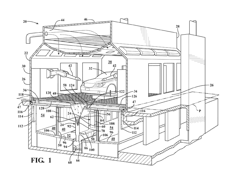
[0010] FIG. 1
is a perspective cross-sectional view of a paint booth assembly
illustrating a scrubber unit extending downwardly from at least one flood
sheet opening of a
flood sheet;
[0011] FIG. 2
is an end view of the paint booth assembly illustrating a shared path of
fluid communication of a flow of water from the flood sheet and a downdraft of
process air
from a spray portion to a paint recovery portion of the paint booth;
3
CA 03111481 2021-03-02
WO 2020/072447
PCT/US2019/053999
[0012] FIG. 3 is a magnified view of a portion of FIG. 2 illustrating a
mixing chute
extending downwardly from a mixing chute mouth disposed adjacent the at least
one flood
sheet opening to a mixing chute exit for establishing a residence time of the
shared path of fluid
communication within the scrubber unit, and a scrubber pod disposed within and
adjacent the
mixing chute mouth to induce an initial mixing of the paint particles into the
flow of water;
[0013] FIG. 4 is a partial perspective cross-sectional view of the paint
booth assembly
illustrating a throat of the scrubber unit disposed between and narrowing
relative to the mixing
chute mouth and the mixing chute exit to induce a subsequent mixing of the
paint particles
entrained in the downdraft of process air into the flow of water;
[0014] FIG. 5 is a partial perspective cross-sectional view of the paint
booth assembly
illustrating a deflection skirt of the scrubber unit extending outwardly from
and contiguously
between a plurality of mixing chutes for containing sludge within a trough;
[0015] FIG. 6 is a partial cross-sectional top view of the paint booth
assembly as
shown in FIG. 1 taken along plane P;
[0016] FIG. 7 is a perspective view of a first embodiment of the scrubber
pod; and
[0017] FIG. 8 is a perspective view of a second embodiment of the
scrubber pod.
DETAILED DESCRIPTION OF THE ENABLING EMBODIMENTS
[0018] Example embodiments will now be described more fully with
reference to the
accompanying drawings. The example embodiments are provided so that this
disclosure will
be thorough and fully convey the scope to those skilled in the art. Numerous
specific details
are set forth such as examples of specific components, devices, mechanisms,
assemblies, and
methods to provide a thorough understanding of various embodiments of the
present disclosure.
It will be apparent to those skilled in the art that specific details need not
be employed, that
example embodiments may be embodied in many different forms, and that neither
should be
construed to limit the scope of the disclosure.
4
CA 03111481 2021-03-02
WO 2020/072447
PCT/US2019/053999
[0019]
Referring to the drawings, wherein like numerals indicate corresponding parts
throughout the several views, a paint booth assembly 20 is generally shown in
FIGS. 1-2 and
includes a paint booth 22 including at least one scrubber unit 24 for removing
paint particles
from a downdraft of air in the paint booth 22. The paint booth 22 includes a
pair of side walls
26 that extend from an entry end 28 to an exit end 30 for receiving a vehicle
32 to be painted.
A conveyor 34 is located centrally between the pair of side walls 26 and
extends from the entry
end 28 to the exit end 30 to convey the vehicle 32 to be painted along the
paint booth 22. A
flood sheet 36 extends between the pair of side walls 26 to separate the paint
booth 22 between
a spray portion 38 disposed above the flood sheet 36 and a paint recovery
portion 40 disposed
below the flood sheet 36.
[0020] As best
illustrated in FIG. 1, a number of paint applicators 42 are ultimately
placed in the paint booth 22 to apply paint particles to the vehicle 32. For
example, the paint
applicators 42 can include rotary-bell-type paint applicators and/or robot-arm-
type paint
applicators. As is known in the art, the paint applicators 42 can include a
pair of paint
applicators 42 that are typically placed on opposite sides of the conveyor 34
to allow the vehicle
32 to be painted from opposite sides at the same time. A plenum 44 extends
along a top portion
46 of the paint booth 22 to introduce a downdraft of air into the spray
portion 38 of the paint
booth 22 to capture and direct an overspray of paint particles that are not
applied to the vehicle
32 in a downdraft of process air from the spray portion 38 towards the paint
recovery portion
40. A water distribution system 47 is placed in communication with the spray
portion 38 to
introduce a supply of flowing water across the flood sheet 36 and passing
underneath the
conveyed vehicle 32 to capture paint particles which escape from the downdraft
of process air,
and also contribute to a clean environment in the paint booth 22. The flood
sheet 36 is generally
flat to aid in even water distribution and cleaning operations for the paint
booth 22.
CA 03111481 2021-03-02
WO 2020/072447
PCT/US2019/053999
[0021] The
flood sheet 36 includes at least one flood sheet opening 48 receiving both
the flow of water from the flood sheet 36 and the downdraft of process air. As
best illustrated
in FIG. 6, in a preferred embodiment, the at least one flood sheet opening 48
includes a plurality
of flood sheet openings 48 extending in a spaced and generally aligned
relationship relative to
one another between the entry and exit ends 28, 30 of the paint booth 22. The
flood sheet
openings 48 each preferably have a flood sheet length LF of approximately 4
feet 7 inches in
length, a flood sheet width WF of approximately 3 feet 2 inches in width, and
are separated by
a gap distance DG of approximately 5 inches such that a flood sheet opening 48
is placed every
five feet from the entry end 28 to the exit end 30. In a preferred embodiment
of the paint booth
assembly 22, at full capacity, approximately 6,000 CFM of air will pass
through each flood
sheet opening 48.
[0022] As best
illustrated in FIGS. 1-2, a pair of dividing walls 50 extend down from
the flood sheet 36 and are disposed in spaced relationship with one another on
opposing sides
of the flood sheet openings 48 to separate the paint recovery portion 40 into
a wet chamber 52
disposed between the pair of dividing walls 50 and a pair of exhaust chambers
54 disposed
between the side walls 26 and the dividing walls 50. A scrubber unit 24
extends down from
each flood sheet opening 48 to establish a shared path of fluid communication
of the flow of
water and the downdraft of process air from the spray portion 38 to the wet
chamber 52 for a
predetermined residence time that provides for mixing the paint particles
entrained in the
process air into the flow of water. As best shown in FIGS. 2 and 3, each
scrubber unit 24
includes a funnel 56 that extends down from a funnel mouth 58 disposed
adjacent one of the
flood sheet openings 48 to a funnel exit 60. The scrubber unit 24 includes a
mixing chute 62
that extends down from a mixing chute mouth 64 that is connected to the funnel
exit 60 to a
mixing chute exit 66 in fluid communication with the wet chamber 52 to define
the
predetermined residence time of the shared path of fluid communication within
the scrubber
6
CA 03111481 2021-03-02
WO 2020/072447
PCT/US2019/053999
unit 24. A trough 68 is located in the wet chamber 52 below and in aligned
relationship with
the mixing chute exits 66, with the mixing chute exits 66 each preferably
extending partially
into the trough 68, so that the trough 68 receives an impingement of the
shared path of fluid
communication and maintains a pool of sludge comprised of the mixed paint
particles and
water.
[0023] The
scrubber unit 24 includes a scrubber pod 70 removably disposed within
the mixing chute mouth 64 of the mixing chute 62. The scrubber pod 70 defines
a plurality of
perforations 72 to induce an initial mixing of the paint particles entrained
in the process air into
the flow of water and cause a pressure drop as the shared path of fluid
communication passes
through the plurality of perforations 72. Put another way, the scrubber pod 70
improves mixing
of the paint particles in the process air into the flow of water by forcing
the paint particles and
flow of water into closer proximity with one another as they collectively pass
through the
plurality of perforations 72 defined by the scrubber pod 70. The plurality of
perforations 72
create a pressure drop that helps pull water particles apart and increases the
proportion that
those smaller water particles will contact paint particles, thus inducing the
initial mixing the
paint particles into the flow of water. The plurality of perforations 72
further function to
increase the uniformity of the initial mixing.
[0024] As best
illustrated in FIG. 7, in a preferred arrangement, the scrubber pod 70
includes a pair of pod surfaces 74 converging towards one another, preferably
at an angle Op
of 40 , from a pod top 76 that is open and designed to be in communication
with the spray
portion 38 to an integral connection along a bottom edge 78. Because of this,
the scrubber pod
70 has a generally triangular prism shape. The plurality of perforations 72
are disposed in a
series along each of the pod surfaces 74 and each extend longitudinally from
the pod top 76 to
the bottom edge 78. In a preferred embodiment, as shown best in FIG. 7, the
perforations 72
have a rhombus shape. However, FIG. 8 shows an alternative embodiment in which
the
7
CA 03111481 2021-03-02
WO 2020/072447
PCT/US2019/053999
perforations 72 have a triangular shape. In either arrangement, the scrubber
pod 70 includes a
lift bar 80 extending centrally between the pod surfaces 74 adjacent the pod
top 76. The lift
bar preferably 80 has a lift hole 82 for allowing a paint booth operator to
remove the scrubber
pod 70 from the mixing chute 62 with a hook on a pole. This allows for easy
removal and
recovery of items blocking the perforations 72 and ease of cleaning of the
scrubber pod 70.
Further, this allows for ease of replacement if the scrubber pod 70 is damaged
or design aspects
are changed.
[0025] As is
best illustrated in FIG. 6, each of the funnels 56 of the scrubber units 24
include four trapezoidal sheets 84 sloping downward from the funnel mouth 58
to the funnel
exit 60 to increase the velocity of the flow of process air and the velocity
of the flow of water
before reaching the scrubber pod 70, improving the mixing action of the paint
particles in the
downdraft of process air into the flow of water. This also serves to evenly
distribute the flow
of water to the scrubber pod 70. Further, as best illustrated in FIG. 3, the
trapezoidal sheets 60
preferably slope down from the funnel mouth 58 to the funnel exit 60 at an
angle OF of 60
relative to the flood sheet 36 to provide a shape of the funnel 56, with the
funnel mouth 58
being wider than the funnel exit 60, that improves airflow from the spray
portion 38 into the
scrubber unit 22. The shape of the funnel 56 also advantageously allows for a
reduction in an
airflow distance DA between the flood sheet 36 and conveyed vehicle 32 and
paint applicators
42, as shown in FIG 1, which can be used to reduce the height of the entire
paint booth 22,
ultimately leading to a reduction in the associated assembly costs and
vertical footprint of the
paint booth assembly 20.
[0026] As best
illustrated in FIGS. 3-4, each of the mixing chutes 62 includes a throat
86 disposed in spaced and adjacent relationship with the mixing chute mouth 64
and mixing
chute exit 66, to define a body portion 92 of the mixing chute 62 that extends
between the
mixing chute mouth 64 and the throat 86 and a terminal portion 94 of the
mixing chute 62 that
8
CA 03111481 2021-03-02
WO 2020/072447
PCT/US2019/053999
extends between the throat 86 and the mixing chute exit 66. The throat 86
narrows from the
body portion 92 to the terminal portion 94 to provide for an additional
pressure drop and a
subsequent mixing of the paint particles in the process air into the flow of
water. This also
increases the velocity of the impingement of the shared path of fluid
communication with the
pool of sludge in the trough 68 for establishing a final mixing of the paint
particles in the
process air into the flow of water. This increased velocity may cause paint
particles, being
heavier than the air, still entrained within the air that have not entered the
water to collide with
and enter the pool of sludge in the trough 68, further reducing the amount of
paint particles in
the air. In the preferred embodiment, the body portion 92 has a body cross-
sectional area and
the terminal portion 94 has a terminal cross-sectional area that is smaller
than the body cross-
sectional area, with both the body portion 92 and the terminal portion 94
being rectangular.
With reference to FIG. 4, the body portion 92 preferably has a cross-sectional
length LB of 2
feet 3 inches, the terminal portion 94 has a cross-sectional length LT of 2
feet 3 inches, the body
portion 92 has a cross-sectional width WB of 11 inches, and the terminal
portion 94 has a cross-
sectional width WT of 8 inches.
[0027] A sloped
floor 96 is located in paint recovery portion 40 and extends in a
downward slope from the pair of side walls 26 towards the trough 68 for
collecting and
directing splashed sludge from the impingement back towards the trough 68
within the wet
chamber 52. A pair of splash guards 98 extend from the sloped floor 96 and
partially covering
the trough 68 to contain splashed sludge produced by the impingement within
the trough 68.
[0028] As best
illustrated in FIGS. 3-5, a deflection skirt 100 extends outward from
the mixing chute 62 of the at least one scrubber unit 24, and at least
partially over the sloped
floor 96 to direct the splashed sludge produced by the impingement towards the
sloped floor
96. The deflection skirt 100 is preferably formed from a collar 102 extending
transverse from
the body portion 92 of the mixing chute 62 and a lip 104 sloping down from the
collar 102,
9
CA 03111481 2021-03-02
WO 2020/072447
PCT/US2019/053999
preferably at an angle OT of 60 . The deflection skirt 100 prevents splashed
sludge from
reaching the exhaust baffles 108 and from being deposited on surfaces other
than the sloped
floor 96 within the wet chamber 52, reducing the regularity with which
cleaning of the wet
chamber 52 is required. The deflection skirt 100 further aids in symmetrically
directing the air
to the exhaust chambers 54. The constant stream of splashed sludge on the
underside of the
deflection skirt 100 has the added benefit of cleaning the deflection skirt
100, and the constant
stream of splashed sludge on the sloped floor 96 has the added benefit of
cleaning the sloped
floor 96. The deflection skirt 100 cleaning itself and the sloped floor 96
reduces maintenance
labor costs as the deflection skirt 100 and the sloped floor 96 will require
manual cleaning less
often. In the preferred embodiment, as best illustrated in FIGS. 4 and 5, the
deflection skirt
100 extends outward and contiguously from the body portions 92 of all of the
mixing chutes
62 from a point near the throats 86. The deflection skirt 100 is also
contiguous from the entry
end 28 to the exit end 30 to further reduce escape of splashed sludge and
reduces machining
and assembly complexity.
[0029] As best
illustrated in FIGS. 1-3, the dividing walls 50 each include and
provide support for exhaust baffles 108 to prevent water and paint particles
from traveling with
the air flowing from the wet chamber 52 to the pair of exhaust chambers 54.
The exhaust
baffles 108 incorporate sloped retaining plates to shed any water paint
particles mixed within
the water that reach the baffles back to the wet chamber 52. The exhaust
baffles 108 are also
located near the top of the dividing walls 50 to allow additional time for
water and paint
particles to drop out of the exhaust air before entering the exhaust chamber
54. The exhaust
baffles 108 improve the cost efficiency of the paint booth 22 by reducing the
amount of paint
particles that escape the wet chamber 52 and have to be filtered out. Baffle
bents provide
additional support for the exhaust baffles 108.
CA 03111481 2021-03-02
WO 2020/072447
PCT/US2019/053999
[0030] The
exhaust chambers 54 each include at least one exhaust air connection 110
at one of the ends 28, 30 to allow the downdraft of air traveling from the
plenum 44 and serially
through the spray portion 38, the wet chamber 52, and the exhaust chambers 54
to exit the paint
booth 22. The exhaust air connections 110 are located high on the ends 28, 30
of the exhaust
chambers 54 to allow for additional contaminants to drop out of the air,
further improving the
paint particle capture of the paint booth 22. The exhaust chambers 54 function
as ducts and, in
cases where there are a total of two exhaust air connections 110, each carries
half of full exhaust
volume within them and avoids the need and additional cost of having external
ducts. In some
embodiments, particularly for longer paint booths 20, such as those that
measure 120 feet or
more from entry end 28 to exit end 30, there will be a total of four exhaust
air connections 110,
one at each end for both exhaust chambers 54. Prior to air leaving through the
exhaust air
connections 110, the air slows down relative to its velocity at the exhaust
baffles 108, allowing
for additional paint particles and contaminants to drop out of the air. This
further improves the
paint particle capture of the paint booth 22 and improves cost efficiency by
reducing how often
filters need to be replaced.
[0031] With
further reference to FIG. 2, the exhaust chambers 54 of the paint booth
assembly 20 preferably split exhaust air into two exhaust chambers 54 to allow
for a reduction
in the height of the paint booth 22 relative to using one exhaust chamber 54,
with associated
cost savings. Splitting the exhaust air into two exhaust chambers 54 provides
a further reduction
in air speed velocity which provides further opportunity for water and paint
particles to drop
out of the exhaust air, increasing the capture efficiency of the paint booth
22. If the paint booth
is longer than 120 feet, the dividing walls 50 can incorporate adjustable
plates to control air
distribution within the exhaust chambers 54. Dividing wall sumps 106 function
as air locks
between the exhaust chambers 54 and the wet chamber 52 and allow cleaning
solutions to flow
from the exhaust chambers 54 to the wet chamber 52. The exhaust chambers 54
have smooth
11
CA 03111481 2021-03-02
WO 2020/072447
PCT/US2019/053999
surfaces for ease of cleaning and to reduce the deposition of material on non-
floor surfaces
within the exhaust chambers 54.
[0032] As
further illustrated in FIG. 2, the water distribution system 47 includes water
distribution headers 112 that provide water to the flood sheet 36. Reduction
pipes 114 in fluid
connection with the water distribution headers 112 increase the velocity of
the flow of water
and reduce scale accumulation. Water entry fittings 116 in fluid connection
with the reduction
pipes 114 direct water to water entry boxes 118 located near the side walls 26
and on the flood
sheet 36 to reduce the kinetic energy of the flow of water and distribute the
flow of water evenly
across the flood sheet 36. The water entry boxes 118 each include a hinge that
allows the entry
boxes to flip up and open to allow for ease of cleaning. A level adjustment
lip 120 that is 2.5
inches in height surrounds each of the flood sheet openings 48 to maintain a
desired water level
on the flood sheet 36 and maintain even distribution of the flow of water into
the scrubber unit
24. A flood sheet drain box 122 with an extended handle 124 allows for
draining of the flood
sheet 36 for cleaning.
[0033] A series
of grates 126 extend between the pair of side walls 26 and the entry
and exit ends 28, 30 in spaced and generally parallel relationship above the
flood sheet 36 to
allow a paint booth 22 operator to move about the spray portion 38 of the
paint booth 22 and
access and service the paint applicators 42. The grates 126 can be removed to
provide access
to the flood sheet 36. A conveyor support 128 extends from each of the side
walls to provide
structural support to the conveyor 34 and the grates 126.
[0034] Although
not illustrated, at least one wet chamber access door can be located
20 in the wet chamber 52 at one of the ends 28, 30 of the paint booth 22 to
provide access to
the wet chamber 52 for maintenance and cleaning. The access door is designed
to be water
tight and utilizes marine style hinges and locks to accomplish this. A sludge
system is in fluid
12
CA 03111481 2021-03-02
WO 2020/072447
PCT/US2019/053999
communication with the trough 68 for receiving and filtering paint particles
out of the sludge.
The trough 68 is generally sloped to direct sludge toward the sludge system.
[0035] The
foregoing description of the embodiments has been provided for purposes
of illustration and description. It is not intended to be exhaustive or to
limit the disclosure.
Individual elements or features of a particular embodiment are generally not
limited to that
particular embodiment, but, where applicable, are interchangeable and can be
used in a selected
embodiment, even if not specifically shown or described. The same may also be
varied in
many ways. Such variations are not to be regarded as a departure from the
disclosure, and all
such modifications are intended to be included within the scope of the
disclosure.
13