Note: Descriptions are shown in the official language in which they were submitted.
CA 03111717 2021-02-26
WO 2020/044289 PCT/IB2019/057301
EXPANDING IMPLANT WITH CUTTING BLADE
CROSS REFERENCE TO RELATED APPLICATIONS
[0001] This application claims priority to and all the benefits of United
States Provisional
Application No. 62/724,768, filed August 30, 2018, the entire contents of
which are hereby
incorporated by reference.
BACKGROUND
[0002] Bone compression fractures may have various causes, such as
osteoporosis, which
may lead to natural vertebral compression under the weight of an individual.
Trauma is another
cause, but it is possible that bone compression may result from a variety of
causes such as a
combination of osteoporosis and trauma. Bone compression may occur in the
vertebra, but may
also occur in other bones, such as the radius and the femur.
[0003] To date, vertebroplasty techniques have been developed in order to
address such
maladies. However, existing vertebroplasty techniques to effect a vertebral
correction, i.e., to
restore a vertebra to its original shape, are often either poorly controlled
and/or may not provide a
structure to ensure that restoration of a bone is preserved over time
following surgery.
[0004] For example, kyphoplasty involves introduction of an inflatable
balloon into the
vertebral body followed by the introduction of fluid under pressure into the
balloon to force the
cortical shell of the vertebra, and in particular the lower and upper
vertebral endplates, to correct
the shape of the vertebra under the effect of the pressure. Once the osseous
cortical shell has been
corrected, the balloon is deflated and withdrawn from the vertebra in order to
be able to inject
cement into the space created by the balloon within the cortical shell, which
is intended to impart
sufficient mechanical resistance for the correction to last a significant
duration in time. Notable
disadvantages of kyphoplasty include its onerous procedural steps and the
necessity to withdraw
the balloon from the patient's body. Furthermore, the expansion of a balloon
is poorly controlled
because the balloon's volume is multi-directional, which often causes a large
pressure to be placed
on the cortical shell in less desirable directions. Such large pressures risk
bursting of the cortical
shell, and in particular, the lateral part of the cortical shell connecting
the lower and upper
endplates of a vertebra.
[0005] In other examples, techniques are employed that utilize implants
which are
-1-
CA 03111717 2021-02-26
WO 2020/044289 PCT/IB2019/057301
intended to occupy a cavity in a vertebra. Such implants, however, often
succumb to collapse
within the weeks and months following surgery as they typically do not support
a large enough
volume within the vertebra. Indeed, the restored height of the vertebra may
diminish over time
following surgery. Specifically, areas of the bone that are remote from the
implant are weak and
over time, compress under loading, even with the implant in place. This could
occur, for example,
in a space below the implant but within the vertebra.
[0006] Thus, a need exists for improved implants and related surgical
techniques for the
repair of collapsed bone structures, particularly improvements to implant
structures and obtainable
performance from such structures.
SUMMARY
[0007] In one aspect, the present disclosure relates to an expandable
implant for bone
restoration. In one implementation, the implant includes a first end element
and a second end
element positioned such that a longitudinal axis of the implant passes through
a center of the first
end element and a center of the second end element. The implant also includes
a plate expandable
in a first direction and a blade expandable in a second direction. A first
interconnecting element
extends between the plate and at least one of the first end element and the
second end element
while a second interconnecting element extends between the blade and at least
one of the first end
element and the second end element. The structure of the implant is such that,
when the implant is
in a collapsed position prior to expansion, a length of the blade is
substantially parallel to the
longitudinal axis, and, when the blade is expanded such that the implant is in
an expanded position,
the length of the blade is non-parallel to the longitudinal axis.
[0008] In one implementation, the plate and the blade are in a single
plane in the
collapsed position and in the expanded position. In another implementation,
when the blade is
expanded in the second direction, a tip of the blade moves in an arcuate
manner, the tip being
remote from an attachment point to the second interconnecting element.
[0009] In other implementations, the blade includes a base adjacent to
the second
interconnecting element and a tip remote from the base, the tip bending when
subject to a
predetermined load. In one implementation, the blade includes a tapered
portion proximal to the
tip of the blade. In another implementation, the blade includes a second
tapered portion between
the first tapered portion and the base, the taper of the second tapered
portion being shallower than
-2-
CA 03111717 2021-02-26
WO 2020/044289 PCT/IB2019/057301
the taper of the first tapered portion. In still another implementation, the
blade includes a recess
across a width of the blade, the recess closer to the tip than the base and
functioning as a pivot
point between portions of the blade on each side of the recess when the tip of
the blade is subject
to a load. In other implementation, the blade includes a planar bottom
surface, the planar bottom
surface becoming wider relative to a width of the blade from the base toward
the tip.
[0010] In one implementation, the tip of the blade is bulbous. In some
implementations,
each of the first interconnecting element and the second interconnecting
element include arms. In
particular, the first interconnecting element includes a first arm extending
between the plate and
the first end element and a second arm extending between the plate and the
second end element.
Similarly, the second interconnecting element includes a third arm extending
between a base of
the blade and the first end element and a fourth arm extending between the
base and the second
end element. In other implementations, when the implant is in a collapsed
position, a first axis
through a length of the third arm is offset from the longitudinal axis a
different amount than a
second axis through a length of the fourth arm, the first and second axes
being parallel. In yet
another implementation, the first axis is offset from the second axis by
approximately 0.6 mm. In
another implementation, the blade pivots about a location on one of the third
arm and fourth arm
when the blade expands in the second direction. In some variants, the third
arm and the fourth arm
each include a longitudinal axis therethrough and an angle between the
longitudinal axis through
one of the third arm and the fourth arm and the length of the blade changes as
the blade expands
in the second direction.
[0011] In one implementation, the blade is expandable in the second
direction such that
the tip of the blade is further from the longitudinal axis than the plate. In
another implementation,
the implant includes a second blade extending directly from one of the first
and second end
elements that prevents the tip of the first blade from moving toward the
longitudinal axis when the
implant is expanded. ht another implementation, one of the third arm and the
fourth arm includes
one of a ball and socket for attachment to the other of the ball and socket on
the blade. In yet
another implementation, the implant includes a frangible material segment
connecting one of the
third arm and the fourth arm to the blade. In one implementation, the tip of
the blade moves away
from the longitudinal axis and toward an insertion end of the implant when
moving in an arcuate
manner during expansion. In another implementation, the tip of the blade moves
away from the
longitudinal axis and away from an insertion end of the implant when moving in
an arcuate manner
-3-
CA 03111717 2021-02-26
WO 2020/044289 PCT/IB2019/057301
during expansion.
[0012] In another implementation, the present disclosure relates to an
implant with a
first end element, a second end element, a plate and a blade. The second end
element is positioned
such that a longitudinal axis of the implant passes through a center of the
first end element and a
center of the second end element. The plate is attached to both the first end
element and the second
end element and is oriented such that an axis parallel to the longitudinal
axis passes through a
length of the plate. The blade includes a base attached to the first end
element and the second end
element and has a length extending from the base to a tip. The implant is
expandable from a
collapsed position to an expanded position, the expansion involving the plate
and the blade each
moving away from the longitudinal axis in different directions. Prior to,
during and following
expansion, the plate remains substantially parallel to the longitudinal axis.
When the implant is in
the expanded position, the tip of the blade is further from the longitudinal
axis than the plate.
Further, a single plane passes through the plate and the blade when the
implant is in the collapsed
position and when the implant is in the expanded position.
[0013] In one implementation, the tip of the blade moves further from the
longitudinal
axis than the base of the blade when the implant is expanded from the
collapsed position to the
expanded position. In another implementation, a second axis passes through the
length of the blade.
In the collapsed position, the second axis is parallel to the longitudinal
axis. During expansion, the
second axis is at an increasing angle relative to the longitudinal axis. In
another implementation,
the plate is attached to the first and second end elements via a first
attachment point that is
equidistant to the first end element and the second end element. Opposite the
plate, the blade is
attached to the first and second end elements via a second attachment point
that is closer to one of
the first end element and the second end element. In yet another
implementation, the tip is a free
end of the blade free of attachment to another element in the collapsed
position, the expanded
position, and at positions in between.
[0014] In yet another aspect, the present disclosure relates to a method
of repairing
a bone. Initially, an implant is introduced into a bone. The implant includes
a first end element, a
second end element, a plate and a blade. A longitudinal axis passes through a
center of the first
end element and a center of the second element. Each of the plate and the
blade are attached to
both the first end element and the second end element. Further, the implant is
expandable from a
collapsed position to an expanded position such that the plate and the blade
are expandable in
-4-
CA 03111717 2021-02-26
WO 2020/044289 PCT/IB2019/057301
different directions. Once the implant is introduced into the bone, an implant
expander tool is
actuated to cause the first end element of the implant to become closer to the
second end element
of the implant as the plate and the blade move from the collapsed position to
the expanded position.
During the actuation, the plate remains substantially parallel to the
longitudinal axis and the blade
rotates about a pivot axis adjacent to one of the first end element and the
second end element. The
blade rotation causes a tip of the blade remote from the pivot axis to move in
an arcuate manner
away from the longitudinal axis. The movement of the plate and the blade
toward the expanded
position creates a cavity in the bone through displacement of material within
the bone, such as
cancellous bone.
[0015] In one implementation, the method includes injecting cement into
the cavity, the
cement traversing nearly an entire depth of the bone between opposing cortical
surfaces. In one
example, the cement flows in between a pair of arms connecting one of the
first end element and
the second end element with the blade as the cement fills the cavity.
[0016] In one implementation, the plate expands a first distance from the
longitudinal
axis and the tip of the blade expands a second distance from the longitudinal
axis. During this
expansion, a difference between the second distance and the first distance
becomes greater as the
implant approaches the expanded position. In another implementation, the blade
includes a portion
adjacent to the tip that bends when subject to a predetermined load during
expansion of the blade.
In yet another implementation, the actuating step involves rotating the
implant expander tool. In
one implementation, the implant undergoes plastic deformation during expansion
such that the
plate and the blade do not return to the collapsed position. In yet another
implementation, the
method includes engaging the implant with a retaining element disposed within
openings in the
first end element and the second end element of the implant. With this
engagement, the retaining
element prevents the implant from moving toward the collapsed position. In yet
another
implementation, the expanded position is reached when the plate contacts a
first cortical bone
surface and the tip of the blade contacts a second cortical bone surface.
[0017] In one implementation, a volume of cancellous bone displaced by
the blade
during rotation of the blade is a function of a length of the blade and a
surface area of the blade
applying load onto cancellous bone during rotation. In one example, the volume
is greater than a
second volume of cancellous bone displaced by the plate during expansion of
the implant.
-5-
CA 03111717 2021-02-26
WO 2020/044289 PCT/IB2019/057301
BRIEF DESCRIPTION OF THE DRAWINGS
[0018] Other objects and advantages of the present disclosure will be
apparent from the
following detailed description of the present preferred implementations, which
description should
be considered in conjunction with the accompanying drawings in which like
reference indicate
similar elements and in which:
[0019] FIG. 1 is a perspective view of an implant in an expanded position
and disposed
within a vertebral body according to one implementation of the disclosure.
[0020] FIG. 2 is a side view of the implant of FIG. 1 in a closed
position.
[0021] FIG. 3 is a side view of the implant of FIG. 1 in the expanded
position.
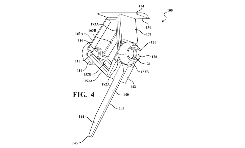
[0022] FIG. 4 is a perspective view of the implant of FIG. 1 in the
expanded position.
[0023] FIG. 5 is a close up perspective view of a portion of the implant
of FIG. 1.
[0024] FIG. 6 is a side view of an implant according to one
implementation of the
disclosure in a closed position.
[0025] FIG. 7 is a close-up side view of a portion of an implant
according to one
implementation of the disclosure.
[0026] FIG. 8 is a side view of an implant according to one
implementation of the
disclosure.
[0027] FIG. 9 is a perspective view of an implant according to one
implementation of
the disclosure.
[0028] FIGs. 10 and 11 are side and bottom views of the implant of FIG.
9.
[0029] FIG. 12 is a side view of a blade of an implant according to one
implementation
of the disclosure.
[0030] FIGs. 13 and 14 are side views of an implant in different
positions according to
one implementation of the disclosure.
[0031] FIGs. 15A, 15B and 16-18 depict various steps of a method of
inserting and
expanding the implant in a bone according to one implementation of the
disclosure.
[0032] FIG. 19 depicts a step in a method of placing an implant into a
bone according to
one implementation of the disclosure.
-6-
CA 03111717 2021-02-26
WO 2020/044289 PCT/IB2019/057301
[0033] FIG. 20 depicts a step in a method of placing an implant into a
bone according to
one implementation of the disclosure.
[0034] FIG. 21 depicts a step in a method of placing a pair of implants
into a bone
according to one implementation of the disclosure
DETAILED DESCRIPTION
[0035] Throughout the disclosure, an expandable implant is described for
use in restoring
a collapsed vertebral body of a human or animal through expansion of the
implant structure once
disposed within the vertebral body. However, although described with
particular reference to
application within vertebral bodies of the spine, it is also contemplated that
the implant of the
implementations herein may be used in other areas of the body. For example,
the implant may be
employed within the cancellous bone in other bones of the body as a
restorative measure when
such bones have collapsed.
[0036] In one aspect, the present disclosure relates to an expandable
implant structure to
repair a collapsed bone structure. In one implementation, an expandable
implant 100 is as shown
in FIGs. 1-5. When in an implanted and expanded position, implant 100 lies
within a vertebra 10
as shown in FIG. 1. Implant 100 includes a first end element 110, a second end
element 120, a
plate 130, a blade 140, and several interconnecting elements in the form of
arms 162, 172, 152A-
B, 182A-B extending between one of the end elements and the plate or blade.
[0037] A shape of implant 100 is largely cylindrical in a closed or
collapsed position
such that a cross section through the implant is at least partially circular,
as shown in FIG. 2 with
the shape of each element shown in FIG. 4. Implant 100 is comprised of
biocompatible material,
for example titanium or titanium alloy, and may be manufactured from a tubular
body using lathe,
laser, and/or electro-erosion manufacturing techniques. Alternatively,
additive manufacturing
techniques or cast manufacturing may be used.
[0038] Implant 100 includes a first end element 110 and a second end
element 120, each
being hollow and having a cylindrical shape with tapered portions as shown in
FIGs. 2-5. In other
examples, the exact shape of the end elements may vary from that shown. In the
implementation
shown in FIGs. 1-5, a leading, or distal, end of the implant near an anterior
side 2 of vertebra 10
corresponds to the second end element 120 while a proximal end closest to a
user inserting the
-7-
CA 03111717 2021-02-26
WO 2020/044289 PCT/IB2019/057301
implant into a bone near a posterior side 4 corresponds to the first end
element 110. The end
elements 110, 120 are intended to be brought towards one another to allow the
expansion of the
implant, as represented by a comparison of FIG. 2 with FIGs. 3 and 4, for
example.
Accordingly, the two end elements 110, 120 are connected to each other through
interconnecting
elements including a first group of upper arms 162, 163A-B and a second group
of upper arms
172, 173A-B via a plate 130, and separately through interconnecting elements
including a first pair
of lower arms 152A-B and a second pair of lower arms 182A-B via a long blade
140. As seen in
FIG. 2, each of these arms is rectilinear and in parallel with the other arms
when implant 100 is in
the closed, i.e., collapsed configuration. The configuration of the upper and
the lower arms is such
that space is provided therebetween in the collapsed position so that a
retaining element or other
actuation structure may fit inside the implant. Notably, a longitudinal axis
of each arm 152A-B is
offset from a longitudinal axis of each arm 182A-B, the offset denoted by
reference numeral 149
in FIG. 2. ht one example, the offset is 0.6 mm to ensure the long blade
rotates away from
longitudinal axis 102 during expansion of the implant. As referenced herein,
longitudinal axis 102
is linear. Longitudinal axis 102 is also referred to herein as linear
longitudinal axis. In other
examples, the offset is an amount ranging from 0.5 mm to 0.7 mm.
[0039] As shown in FIG. 4, each of first end element 110 and second end
element 120
includes an opening therethrough, 111 and 121, respectively. These openings
111, 121 are sized
to accommodate the placement of a shaft of a tool therein, e.g., retaining
element 103, the shaft
being rotatable to control actuation of the implant. Further, an inner surface
116, 126 of the
respective end elements 110, 120 may include ridges, threads or other
engagement features to
provide for controlled interaction between the tool and the implant. In one
example, the first end
element 110 or second end element 120 which is operational as a distal end of
the implant may
include a cavity with an enclosure on one side instead of a through opening so
that the end element
is entirely closed on an outward facing surface facing away from the remainder
of the implant.
[0040] Continuing to refer to the end elements, first end element 110
includes a first
inward facing surface 114 as shown, for example, in FIGs. 2-5. First inward
facing surface 114 is
ring shaped with opening 111 passing therethrough. Extending from first inward
facing surface
114 are upper arms 163A-B, upper arm 162, lower arms 152A-B, and short blade
150. Taking
plate 130 to be on an upper portion of implant 100 and long blade 140 to be on
a lower portion,
-8-
CA 03111717 2021-02-26
WO 2020/044289 PCT/IB2019/057301
upper arm 162 extends from first inward facing surface 114 to plate 130 from a
location on surface
114 above the other arms. Immediately below upper arm 162 and also extending
from surface 114
to plate 130 is a pair of upper arms 163A-B, as shown in FIG. 4. Upper arm
163A extends from a
lateral side of surface 114 opposite that of upper arm 163B, as shown in FIG.
4. Extending from
surface 114 below the upper arms to long blade 140 is a pair of lower arms
152A-B. In a manner
similar to arms 163A-B, lower arm 152A extends from a lateral side of surface
114 opposite that
of lower arm 152B. A space in between attachment locations of arms 152A and
152B, respectively,
accommodates attachment of short blade 150 to end element 110. In this manner,
short blade 150
extends from surface 114 in between lower arm 152A and lower arm 152B to a
free end tip 151,
as shown in FIGs. 2 and 5, for example. Short blade 150 includes a top surface
in parallel with
axis 102 and includes a tapering bottom surface 153 such that the short blade
becomes smaller
towards free end tip 151.
[0041] Second end element 120 includes a second inward facing surface 124
with arms
172, 173A-B and 182A-B extending therefrom in the same manner as described
above for first
end element 110. Thus, each of upper arms 172, 173A-B extend from second
inward facing surface
124 to plate 130 while each of lower arms 182A-B extend from second inward
facing surface 124
to long blade 140.
[0042] Plate 130 includes a convex upper surface 134 as shown in FIG. 4,
curved in
a direction transverse to axis 102. While implant is in a closed position, as
shown in FIG. 2, plate
130 has a length close to a distance between first and second end elements
110, 120. In other
variations, the length of the plate relative to the distance between the first
and the second end
elements may be greater or lesser than that shown in FIG. 2. In a central
region of plate 130 and
extending inward from a body of plate 130 toward axis 102 is a base portion
132. Base portion has
a length extending over a central portion of the plate length between a first
end surface 135 and a
second end surface 136. Arms 162, 163A-B extend from first end surface 135 of
base portion 132
while arms 172, 173A-B extend from second surface 136 of base portion 132, as
best shown in
FIGs. 3 and 5. Base portion 132 is one example of an attachment point between
plate 130 and the
upper arms.
[0043] As noted above, the upper arms include first group of upper arms
162, 163A-
B and second group of upper arms 172, 173A-B. Having described where each arm
interfaces with
-9-
CA 03111717 2021-02-26
WO 2020/044289 PCT/IB2019/057301
other structures of implant 100 at its ends, we turn to the structures of the
arms themselves. Upper
arms 162, 172 each have a width close to a diameter of the first and the
second end elements.
Upper arms 163A-B and 173A-B are pairs of arms below arms 162, 172,
respectively, and are
narrower than arms 162, 172. Each of the upper arms (and lower arms) has a
thin web of material,
also described as a material web, at its opposite ends. This material web
undergoes plastic
deformation when subject to loading, thereby functioning as an effective pivot
point for adjacent
elements. Put another way, through plastic deformation of the web material, an
arm folds under
the plate (or blade) as the first end element and the second end element are
brought closer to one
another, while the plate translates, or blade rotates, away from the central
linear axis 102. Further,
the material web is an articulation area formed by the thinning of a wall that
is interposed between
an end element and the plate or the blade. In one example, the material web is
a weakened zone of
material. In another example, the material web is formed through fabrication
of a groove in the
arm. Such a material web provides one example of a material web that is
plastically deformable
without breaking. In some examples, the material webs control the expansion of
the implant by
deforming in a predetermined manner to a predetermined extent. Further
variations on the material
web may be as described in U.S. Pat. Nos. 7,846,206 (the '206 Patent),
8,986,386 (the '386 Patent),
and 9,414,933 (the '933 Patent), the disclosures of which are hereby
incorporated by reference
herein.
[0044] On the upper arms, arm 162 has webs 164, 166, and arms 163A-B have
webs
167A-B, 168A-B. One end of each arm 162, 163A-B abuts first end element 110
while the other
abuts surface 135 of base portion 132. Similarly, upper arms 172 and 173A-B
opposite the
aforementioned arms also include material webs at their ends abutting surface
124 of second end
element 120 at one end and surface 136 of base portion 132 at an opposite end.
In particular,
material webs 174, 176, 177A-B and 178A-B correspond to material webs 164,
166, 167A-B and
168A- B, respectively.
[0045] Long blade 140 includes a base 142 attached to the remainder of
implant 100 and
has a length extending from base 142 to a free end tip 145, as shown in FIGs.
2-4. Tip 145 is a free
end in that it is free of attachment to another element in the collapsed
position, the expanded
position, and at positions in between. Long blade 140 includes a central
portion 141 and a tapered
portion 144, the tapered portion terminating at free end tip 145. With tapered
portion 144, long
-10-
CA 03111717 2021-02-26
WO 2020/044289 PCT/IB2019/057301
blade 140 has a tip that is sharpened to an extent. The geometry of long blade
140, particularly the
tapered portion, improves its ability to bend when subject to loading. A lower
surface of long
blade, facing away from the remainder of implant 100, is defined by a ridge
146 having a peak
aligned with a central axis of long blade 140 and extending along a length of
blade 140, as best
shown in FIG. 4. The length of blade 140 is such that free end tip 145 extends
directly under short
blade 150 when implant 100 is in a collapsed position, as shown in FIG. 2. In
particular, tapered
portion 144 of long blade 140 is positioned directly under tapered surface 153
of short blade 152
when the implant is in the collapsed position such that short blade 150 does
not prevent long blade
140 from being positionable parallel to linear longitudinal axis 102.
Nonetheless, free end tip 145
of long blade 140 is close to first inward facing surface 114 when implant 100
is in the collapsed
position. As noted above, blade 140 is connected to the remainder of implant
100 via first pair of
lower arms 152A-B extending from a first end 147 of base 142 and second pair
of lower arms
182A-B extending from a second end 148 of base 142. Base 142 is one example of
an attachment
point between the long blade and the lower arms.
[0046] As seen in FIG. 2, base 142 is positioned closer to second end
element 120 than
first end element 110 such that arms 152A-B are much longer than arms 182A-B.
The position of
base 142 on the implant provides room for blade to extend across a significant
portion of the
implant length so that a longer blade is accommodated. As will be described in
greater detail below,
the longer blade is advantageous in that it allows for a larger sweeping
motion below the implant
to remove a greater volume of cancellous bone from the proximal end of the
implant toward the
distal end of the implant as the blade sweeps downward, as shown in FIG. 3, or
alternatively, from
the distal end to the proximal end, when the implant is structured with a
blade oriented in an
opposite direction.
[0047] Lower arms 152A-B include structure similar to that of the upper
arms described
above. Each lower arm 152A, 152B has a length extending from first end element
110 to long
blade 140, a material web 154A-B abutting first end element 110 and a material
web 156A-B
abutting base 142 of long blade 140. As shown in FIGs. 4 and 5, a gap exists
between arms 152A
and 152B. Lower arms 182A-B include a material web adjoining second end 148 of
base 142 to
second end element 120. As shown in FIGs. 2 and 3, lower arms 182A-B have a
constant thickness
over their respective lengths, although it is contemplated that the specific
sectional dimensions
-11-
CA 03111717 2021-02-26
WO 2020/044289 PCT/IB2019/057301
may vary over the arm length. In one example, the lower arms between base 142
and second end
element 120 include a larger cross-sectional size further from their ends to
cause plastic
deformation to occur at a desired point on the arm, such as adjacent to the
second end element. As
shown in FIGs. 2-4, expansion of plate 130 and long blade 140 occur in a
single plane. Thus, in
the collapsed position shown in FIG. 2, in the expanded position shown in FIG.
3, and in positions
in between, the plate, long blade, and arms of the implant are all in a
single, common plane.
[0048] In one implementation, implant 200 is as shown in FIG. 6. ht FIG.
6, like reference
numerals refer to like elements, and unless otherwise indicated, referenced
elements may be as
described for implant 100, but within the 200-series of numbers. Implant 200
includes a first end
element 210, a first inward facing surface 214, a second end element 220, a
second inward facing
surface 224, a plate 230, and a long blade 240. Long blade 240 is attached to
first end element 210
and second end element 220 via first pair of lower arms 252A-B and second pair
of lower arms
282A-B, respectively. The first pair of lower arms 252A-B extending from a
first end 247 of base
242 and the second pair of lower arms 282A-B extending from a second end 248
of base 142.
Lower arms 252A-B include material web 254A-B at an end abutting first end
element 210 while
at an opposite end, arm 252A-B forms one part of a ball and socket joint. As
shown in FIG. 6, each
of arms 252A-B provide the ball component while the first end 247 of base 242
of blade 240
provides sockets (not shown) corresponding to the ball components. In this
manner, a surface at
the first end 247 of base 242 includes recessed surfaces (not shown) to
receive the ends of arms
252A-B. In an alternative configuration, the elements are reversed such that
the arms 252A-B have
a socket on their end surfaces and base 242 has protrusions to define the ball
of the ball and socket.
The ball and socket is designed so that long blade 240 and arms 252A-B pivot
about the ball and
socket connection, while the connection point rotates away from linear axis
202. This rotational
movement minors that occurring during expansion of implant 100 that includes
material web
156A-B, such as is shown in FIGs. 2-3. As such, the ball and socket connection
provides for the
relative movement of elements as described in implementations having a
material web connection
between the lower arm and the long blade while also preserving the attachment
between lower
arms 252A-B and long blade 240 during expansion. Additionally, in this
arrangement arms still
undergo one way expansion via plastic deformation of material webs 254A-B and
282A-B, for
example. It should be appreciated that functional equivalents of a ball and
socket joint may also
-12-
CA 03111717 2021-02-26
WO 2020/044289 PCT/IB2019/057301
be used in place of the ball and socket of this implementation.
[0049] In one implementation, an implant 300 includes lower arms 352A-B
attached to
long blade 340 through a frangible material segment 356A as shown in FIG. 7.
Frangible material
segment 356A provides the only connection between each lower arm 352A-B and
long blade 340,
and it can be seen in FIG. 7 that an end face of arms 352A-B is not attached
to first end 347 of
base 342. Frangible material segment 356A provides a support function so that
prior to use of the
implant, when the implant is closed and in the collapsed position, blade 340
is held in position in
part through support by the arms 352A-B via frangible material segment 356A,
as shown in FIG.
7. However, implant 300 is structured so that when load is applied to the
first end element, i.e.,
when the first end element of the implant moves closer to the second end
element, and the plate
and blade are subject to loads causing them to move further apart and expand,
movement of arms
352A-B and long blade 340 causes tension therebetween such that frangible
material segment
356A breaks. In this manner, implant 300 is structured so that long blade 340
is pivotable about
the lower arm located between base 342 and the second end element upon
breakage of frangible
material segment 356A.
[0050] In FIG. 8, another implementation of the implant is shown where
like
reference numerals refer to like elements, within the 400-series of numbers.
Implant 400 includes
a first end element 410, a second end element 420, a plate 430, a base 432, a
group of upper arms
462, 463A-B, 472, 473A-B, a long blade 440, and a group of lower arms 452A-B,
482A-B. Lower
arms 452A-B, 482A-B and blades 440, 450, however, are reversed relative to the
end elements of
implant 100. In particular, base 442 of long blade 440 is adjacent to first
end 410 of implant 100.
In this manner, implant 400 is configured so that when first end element is
moving closer to second
end element during expansion of the implant, free end tip 445 of long blade
440 arcs away from
central axis 402. This arcuate motion is downward and away from second end
element 420 and in
a proximal direction toward the user. Thus, when implant 400 is inserted into
a vertebra, for
example, long blade 440 is attached so that it expands in an arcuate manner
from an anterior side
toward a posterior side of the vertebra.
[0051] In FIGs. 9-11, another implementation of the implant is shown
where like
reference numerals refer to like elements, within the 500-series of numbers.
Implant 500 includes
a first end element 510, a second end element 520, a plate 530, a base 532, a
group of upper arms
-13-
CA 03111717 2021-02-26
WO 2020/044289 PCT/IB2019/057301
562, 563A-B, 572, 573A-B, a long blade 540, and a group of lower arms 552A-B,
582A-B. As
shown in FIG. 9, each of first end element 510 and second end element 520
includes an opening
therethrough, 511 and 521, respectively. These openings 511, 521 are sized to
accommodate the
placement of a shaft of a tool therein, e.g., retaining element 503 with
ridged portion 504, the shaft
being rotatable to control actuation of the implant. Retaining element 503
includes egress apertures
505A, 505B, through which cement 30 exits retaining element 503 and enters the
cavity within the
bone.
[0052] FIG. 10, shows that arms 582A-B, effectively material webs,
connecting blade
540 to first end element 510, are thicker than corresponding material webs
564, 567A-B of the
upper arms. Because there is only one arm layer on the lower side of the
implant, the material web
is thicker to compensate for the single level of support and to provide
sufficient capacity to transfer
loads. In one example, arms 582A-B are 0.4 mm thick. Additionally, as shown by
reference
numeral 549 in FIG. 10, a longitudinal axis through arms 582A-B is offset from
a longitudinal axis
through arms 552A-B such that arms 552A-B are further from linear longitudinal
axis 502. The
arms are offset by an amount to optimize the expansion function of the blade,
i.e., to ensure the
blade expands outwardly when first end element and second end element move
toward one
another. In one example, the offset is 0.6 mm. In other examples, the offset
is an amount ranging
from 0.5 mm to 0.7 mm. Inclusion of arms offset 549 from one another on the
lower side of the
implant is rendered simpler due to the additional space available with only a
single layer of arms
on the lower side of implant 500, as shown in FIG. 10.
[0053] On the upper arms, upper arm 562 has webs 564, 566, and arms 563A-
B have
webs 567A-B, 568A-B. One end of each arm 562, 563A-B abuts abutting surface
524 of second
end element 520 while the other abuts surface 535 of base portion 532.
Similarly, upper arms 572
and 573A-B opposite the aforementioned arms also include material webs at
their ends abutting
first end element 510 at one end and surface 536 of base portion 532 at an
opposite end. In
particular, material webs 574, 576, 577A-B and 578A-B correspond to material
webs 564, 566,
567A-B and 568A- B, respectively.
[0054] As shown in FIGs. 9-11, blade 540 is flat on an upward facing side
541 and wider
relative to an outer width of the implant compared to long blade 140. In
particular, FIG. 11
illustrates that a width of long blade 540 through tapered portions 543, 544
is only slightly
-14-
CA 03111717 2021-02-26
WO 2020/044289 PCT/IB2019/057301
narrower than base 542, where base 542 has a width corresponding to an outer
width of implant
500. Blade 540 includes a first tapered portion 543 extending from base 542
and a second tapered
portion 544 extending from first tapered portion 543 to tip 545. Each tapered
portion is defined by
a planar surface, as shown in FIG. 11, becoming wider toward tip 545. Bottom
surfaces 546 outside
the planar tapered portions 543, 544 may be slightly curved or rounded, again,
shown in FIG. 11.
The geometry of blade 540, and in particular, its downward facing surface
area, shown in FIG. 11,
for example, is maximized relative to the outer dimensions of the implant. Put
another way, a
length of the blade is close to a length of the implant while a width of the
blade is close to a width
of the implant. This geometry maximizes the capacity of the blade to displace
material, such as
cancellous bone, as the implant is expanded. Tip 545 is rounded or bulbous,
and extends across
the width of long blade 540. In one example, an angle of taper for first
tapered portion is two
degrees and for second tapered portion is four degrees. In this example,
providing a second tapered
portion 6 to 7 mm in length further optimizes the ability of the long blade to
bend when subject to
a predetermined load. A second tapered portion 6.7 mm in length is
particularly advantageous. In
this and other examples, the sectional radius of rounded tip may be 0.30 mm.
In one example, the
long blade is 4.1 mm in width while the widest location on the planar surface
of the second tapered
portion adjacent to the tip is 3.6 mm.
[0055] Base 542 of long blade 540 is adjacent to first end element 110 so
that free end tip
545 of long blade 540 arcs away from second end element 120 and toward first
end, i.e., in a
proximal direction. In an alternative configuration, the base may be
positioned in a reverse
configuration and adjacent to the second end element 120 so that tip 545 of
long blade 540 arcs
away from linear longitudinal axis 502 in an opposite direction from that
exhibited by implant 500
shown in FIG. 9.
[0056] As discussed above, one advantage of implant 500 when inserted and
expanded in
a bone structure, such as a vertebra, is that it includes a blade with a large
surface area, so that
during an expansion process when the blade arcs away from linear longitudinal
axis 502, a volume
of cancellous bone is displaced that corresponds to the width of the blade,
the large relative width
of the blade increasing the volume displaced. In turn, the increased
displacement of cancellous
bone creates a wider cavity below the implant so that a greater amount of
cement can be disposed
therein to complete a repair using the implant. Additionally, in instances
where the blade path
-15-
CA 03111717 2021-02-26
WO 2020/044289 PCT/IB2019/057301
causes the tip of the blade to contact a lower plate, the geometry of the
blade is such that the blade
bends and otherwise deforms when subject to loading, due to contact with a
cortical bone surface,
for example, thereby reducing the possibility that tip 545 of blade will
puncture the vertebral body
when load continues to be applied to blade after it makes contact with the
cortical bone. This
advantage is further enhanced because tip 545 of blade 540 is rounded, as
shown in FIGs. 9
and 10, for example, reducing the risk of cortical bone puncture.
[0057] In another implementation, the implant of FIGs. 9-11 includes a
blade 640 as
shown in FIG. 12. This blade includes base 642, and a weak section in the form
of recess 649
across the blade width defining a weak point in the blade structure. In other
respects, like reference
numerals refer to like elements in implant 500. Blade 640 is advantageous in
that when blade 640
is under load and in contact with a cortical bone, a distal portion 644 of
blade 640 between recess
649 and free end 645 will bend or break from the remainder of the blade and,
irrespective of
whether distal portion 644 bends or breaks, blade 640 will not penetrate the
bone. This provides
an added measure of protection to ensure no cortical bone is punctured when
the implant is inserted
into and expanded within a vertebral body. In other examples, a feature
similar to recess 649 may
be employed in a blade of any implant implementation described herein.
[0058] In yet another implementation, an implant 700 includes two blades:
an upper
blade 770 and a lower blade 740, as shown in FIGs. 13 and 14. Unless otherwise
noted, like
reference numerals refer to like elements. Below linear longitudinal axis 702
is lower blade 740
and above linear longitudinal axis 702 is upper blade 770. Arms 782A-B connect
the lower blade
740 to first end element 710, and arms 752A-B connect the lower blade 740 to
the second end
element 720. Likewise, arms 777A-B connect the upper blade 770 to first end
element 710, and
arms 763A-B connect the upper blade 770 to the second end element 720. The
arms 752A-B,
763A-B, 777A-B, 782A-B may be similar or the same as those in implant 500, for
example.
Implant 700 is symmetrical, and accordingly, features of upper arms and blade
770 are the same
as those for lower arms and blade 740. FIG. 13 illustrates implant 700 in a
collapsed position while
FIG. 14 illustrates implant 700 in an expanded position.
[0059] The implant structure may be varied in many ways. For example,
upper arms
connecting an end element with the plate may be arranged so that a single arm
connects the first
end element to the plate and a single arm connects the second end element to
the plate. To
-16-
CA 03111717 2021-02-26
WO 2020/044289 PCT/IB2019/057301
accommodate this structure, the web of each arm may have a greater thickness
than in other
implementations so that each arm can bear greater loads. In other
configurations, the arms may be
offset to a greater extent relative to a central longitudinal axis of the
implant to provide space for
a retaining element. An increased offset may be desirable where the arms are
of larger cross-
sectional size. Similar variations are possible in the lower arms. In another
example, an implant
includes a plate above a central longitudinal axis and two blades adjacent to
one another below the
central longitudinal axis. In this configuration, the two blades expand in a
matching arcuate
movement when the first and second end elements of the implant move toward one
another. In
other examples, a long blade of the implant may include a hinge in place of a
recess so that a free
end portion of the blade rotates upon contact with a cortical bone to prevent
puncture during
expansion of the blade. In yet another example, the tip may include a spring
feature to serve a
similar function. In other examples, the blades of the various implementations
described herein
may include rounding features at a tip of the blade to minimize the risk of
cortical bone puncture
during use. In still further examples, a cross-sectional shape of the plate,
short or long blade, arms
and end elements may vary from that shown in the depicted implementations. In
other examples,
the position of the long blade relative to the implant ends may be reversed
relative the orientation
described for each of the above implementations. Thus, if the long blade moves
in an accurate
manner from the anterior side of the vertebra toward the posterior side, it
may also be structured
to rotate from the posterior side to the anterior side.
[0060] In another aspect, the present disclosure relates to systems for
repairing vertebral
bodies. In one implementation, a system includes implant 100 and retaining
element 103 attached
thereto via placement of retaining element 103 into first and second end
elements 110, 120 of
implant 100, respectively. One example of such a system is shown in FIG. 1.
Retaining element
103 provides a structure upon which end elements 110, 120 may be brought
closer together through
plastic deformation of the arms, e.g., material webs on the arms, while
ensuring that implant 100
does not collapse after expansion.
[0061] In another implementation, a system may include an implant, a
retaining element
and an implant expander. In such an implementation, the implant expander is
placed over the
retaining element and contacts the implant during use when actuating the
system to expand the
implant. In yet another implementation, a system may include an implant, a
retaining element, an
-17-
CA 03111717 2021-02-26
WO 2020/044289 PCT/IB2019/057301
implant expander and an injector transfer tube. With a fully expanded implant,
the injector transfer
tube is advanced and positioned within the implant expander. The injector
transfer tube is
configured so that cement filler may be injected from within the injector
transfer tube into the bone
structure repaired by the implant.
[0062] In another aspect, the implant may be included together with other
tools as a kit.
In one implementation, a kit includes two implants, and one or more of an
implant expander, a
trocar, a guidewire, a reamer, a template, a cannula plug and an injector
transfer tube. In a variant,
a plurality of any one of the aforementioned tools may be included. In a
further variant, the kit
includes a single implant along with a combination of the aforementioned
tools. In yet another
variant, the kit includes three or more implants. If the kit includes more
than a single implant, the
implants within the kit may vary in overall size or materials, from which the
most suitable implant
may be chosen for a particular surgery. Any combination of implants and tools
may also be
included in a single package or in separate packages which may be later
brought together as a kit.
[0063] The kit may be varied in many ways. For example, it is
contemplated that any
combination of particular implants and tools as described herein may further
include other tools or
instruments not otherwise described as part of a kit. The various combinations
of elements of any
contemplated kit may be included in a single package or distributed among
multiple packages. In
other examples, the kits contemplated herein may be accompanied by an
instruction manual on
how to perform one or more of the methods of using the contents of the kit.
[0064] In another aspect, the present disclosure relates to a method of
using an implant
to repair a collapsed bone structure. One implementation of this method is
depicted in FIGs. 15A,
15B and 16-18. Initially, implant 100 is inserted into a collapsed bone
structure such as a vertebral
body, for example. This may be accomplished with the use of tools such as an
implant expander
190 shown in FIG. 15A. To use the implant expander, the implant is attached to
a distal end of the
implant expander. In one example, this may be accomplished through threaded
engagement
between a rod (not shown) extending through a tube of the implant expander and
an interior surface
within second end element 120 of the implant. When the implant is attached,
the tube of the implant
expander that surrounds the rod abuts first end element 110. The tube is sized
to pass over an
exposed portion of retainer element 103. When the implant is first inserted,
it is in a collapsed
position, as shown in FIGs. 15A-15B. In some examples, the steps preceding
insertion of the
-18-
CA 03111717 2021-02-26
WO 2020/044289 PCT/IB2019/057301
implant for the preparation of a portal into the vertebral body may be as
described in the '206, '386
and '933 Patents. In another example, preparation involves the insertion of a
trocar into the bone,
followed by placement of a guidewire through the trocar. A portion of the
trocar is then removed
so that a reamer may be slid over the guidewire. This is followed by drilling
into the bone and
cleaning the drilled pathway. Other tools may also be used at this juncture,
such as a cannula plug
to verify the dimensions of the portal for implant placement. In the
implementation shown in FIG.
15A, two portals in vertebra 10 are prepared for two implants 100, 100A,
respectively.
Nonetheless, it is contemplated that a repair may involve the placement of a
single implant or
multiple implants into the bone, a quantity of implants inserted chosen based
on the severity of the
deterioration or injury, and/or the size of the bone, for example.
[0065] With implant 100 in a desired position within the vertebral body,
implant expander
190, and 190A if two portals in vertebra 10 are prepared for two implants 100
and 100A, is actuated
by rotating a handle on the implant expander, denoted by 191 in FIG. 15A.
Rotation of the handle
causes the rod within the implant expander to translate axially toward the
handle while
simultaneously first end element 110 becomes closer to second end element 120.
One example of
a handle that provides such function includes an internal structure that
converts the rotational
actuation into a linear translation. During this process, the tube abutting
first element 110
translates the same amount but in an opposite direction to translation of the
second end element.
Turning to FIG. 15B, retaining element 103 includes a ridged portion 104 so
that as first end
element 110 becomes closer to second end element 120, inner surface 116
defining opening 111
through first end element 110 is incrementally engageable with corresponding
ridges 104 on
retaining element 103. This is one feature that prevents implant 100 from
returning to the collapsed
position after expansion.
[0066] When first end element 110 moves toward second end element 120,
each of the
arms of implant 100 pivot about the end elements to which the arms are
attached. In particular,
and as shown in FIG. 16, arms 162, 163A-B pivot upward about their respective
webs 164,
167A-B, along with a similar pivoting motion in the other upper arms 172, 173A-
B. As the arms
pivot, plate 130 translates upward in a plane through the implant while a
length of plate 130
measured on bearing surface 134 remains parallel to linear longitudinal axis
102 (compare FIGs.
15B and 16). It should be appreciated that the orientation of the plate and
the linear longitudinal
-19-
CA 03111717 2021-02-26
WO 2020/044289 PCT/IB2019/057301
axis may be substantially parallel, and that the plate may be oriented at a
slight angle relative to
the longitudinal axis due to surgical conditions or tolerances in the
manufactured implant. As the
plate translates in an upward direction, cancellous, i.e., soft bone within
the vertebra is displaced
by the plate. On the lower side of the implant, movement of end elements 110
and 120 toward one
another cause arms 152A-B to pivot about material webs 154A-B, 156A-B and arms
182A- B to
plastically deform, arms 182A-B functioning as material webs. This, in turn,
causes long blade
140 to move in an arcuate manner about arms 182A-B, the arcuate movement being
in the plane
through the implant and in a downward direction. As with the expansion of the
plate, arcuate
movement of long blade 140 causes cancellous bone to be displaced in its path.
Because of the
length of long blade 140 and its path through the cancellous bone as it pivots
about arms 182A-B,
significantly more cancellous bone is displaced by long blade 140 compared
with the upper plate
130. This is clear from FIG. 17, where a path of the blade on the lower side
of the implant extends
to a lower plate 12 of vertebral body 10 while a path of the plate on the
upper side extends to the
much closer upper plate 14 of vertebral body 10. The sharpened shape of long
blade 140 through
tapered portion 144 toward tip 145, best shown in FIG. 4, promotes cutting
through the cancellous
bone while the blade is rotated to reduce resistance during the expansion
process. As noted above,
deformation in the material webs that facilitates the pivoting action of the
arms is plastic
deformation, and accordingly, the plate and blade will remain in an expanded
position following
expansion.
[0067] During the expansion procedure, long blade 140 rotates due to base
142 being
closer to second end element 120 than it is to first end element 110 and arms
152A-B being longer
than arms 182A-B, as shown in FIG. 16. Rotation is also facilitated due to
offset 149 between arms
152A-B and arms 182A-B. Thus, as the lower arms pivot, base 142 rotates
counterclockwise,
causing tip 145 of long blade 140 to travel in an arc from its starting
position shown in FIG. 15B
toward anterior side 2 and bottom plate 12 of vertebra 10 (shown in a later
procedural step in FIG.
18). As an added measure to ensure long blade 140 travels downward, short
blade 150 is positioned
to prevent long blade 140 from rotating toward a central region of the
implant. In its starting
position, long blade 140 is parallel to linear longitudinal axis 102, as shown
in part in FIG. 15B.
During expansion, long blade 140 becomes angled relative to linear
longitudinal axis 102 and
moves further away from linear longitudinal axis 102 as end portions 110, 120
are moved toward
-20-
CA 03111717 2021-02-26
WO 2020/044289 PCT/IB2019/057301
one another. Because arms 152A-B are positioned on lateral sides of short
blade 150, each arm
152A-B pivots past short blade 150 without interference.
[0068] FIG. 16 shows implant 100 partially expanded. Once implant 100 is
fully actuated,
it is positioned as shown in FIG. 17. One advantage of implant 100 is that
through its expansion,
plate 130 operates to restore the depth, i.e., height, of the vertebral body
above the implant. Another
advantage of bone restoration using implant 100 is that, when expanded, it
creates a path for
cement in the bone that traverses nearly the entire depth of the vertebral
body through the
expansion of plate 130 and blade 140. In particular, and as is shown in FIG.
17, this is
accomplished through the formation of a cavity extending between surface 134
of plate 130
abutting an interior cortical surface of top plate 14 and tip 145 of blade 140
abutting an interior
cortical surface of bottom plate 12. As will be described further below, the
creation of a cavity
extending between plates 12 and 14 provides room for cement to be deposited
throughout a depth
of the vertebral body thereby creating a more durable repair than one where
cement only fills a
portion of the bone depth. Additionally, in variants where the plate and/or
the blade have a width
close to that of the implant, compared to variants with plates and/or blades
having a narrower
width, a volume of cancellous bone displaced is maximized, further increasing
the amount of
cement that can be disposed in the bone cavity for the repair and improving
the distribution
of cement in the cavity. Thus, implant 100 is used to create a cavity so that
sufficient cement is
deposited throughout the bone depth to minimize any loss of restored bone
height following
surgery.
[0069] Although long blade 140 is shown expanded at a particular angle in
FIG. 17, the
angle for full expansion may be varied as a matter of design choice to suit
surgical needs. For
example, an angle between linear longitudinal axis 102 and long blade 140 in
the expanded
position may be thirty degrees, sixty degrees or eighty degrees. In one
example, as the implant is
expanded toward the expanded position, the plate expands a first distance from
the linear
longitudinal axis and the tip of the blade expands a second distance from the
linear longitudinal
axis in a manner such that a difference between the second distance and the
first distance becomes
greater as the implant becomes closer to reaching the expanded position. In
some examples, a
distance from the linear longitudinal axis of the implant to the tip of the
blade is nearly three times
a distance measured from the linear longitudinal axis to the plate when the
implant is fully
-21-
CA 03111717 2021-02-26
WO 2020/044289 PCT/IB2019/057301
expanded.
[0070] Once implant 100 is properly positioned and fully expanded, an
injector transfer
tube 195 is inserted over retaining element 103 and cement 30, e.g., bone
cement, is injected
through the transfer tube and into a space within the vertebra previously
cleared of cancellous
bone, as described above. Retaining element 103 includes egress apertures
105A, 105B, through
which cement 30 exits retaining element 103 and enters the cavity within the
bone, as shown in
FIG. 18. This form of cement injection is also described in at least some
implementations of the
'206, '386 and '933 Patents, along with other alternatives and variations. As
cement 30 is injected
into the cavity through the egress apertures 105A, 105B, it flows at least in
part through the gap
between arms 152A and 152B. Thus, the gap between arms 152A, 152B provides
improved flow
of cement into the cavity, thereby improving the overall structural repair.
Because the cavity
formed in the vertebra extends close to respective plates 12 and 14, i.e.,
cortical bone endplates,
the cement fills nearly the entire, or in some cases the entire depth of the
vertebra. The cement
thereby fulfills a load bearing function between plates 12 and 14 once the
cavity is filled. Put
another way, since the cement is disposed through the depth of the vertebral
body, it functions to
prevent the bone from collapsing over time, as there is little to no bone
depth without support
provided by the cement. Further, even where implant 100 does not have plate to
plate contact as
shown, the plate and blade are each close enough to the cortical bone surfaces
in the expanded
position so that cement injected into the bone ensures that recompression of
the bone is prevented
or minimized following the restoration procedure. In some examples, a second
implant, such as
implant 100A shown in FIG. 15A, may be expanded in conjunction with and
simultaneous to the
expansion of implant 100. The steps for expanding implant 100A from a
collapsed position to an
expanded position are the same as those for implant 100.
[0071] In another implementation of the method, blade 140 is longer than
a distance
from linear longitudinal axis 102 of implant 100 to a bottom plate 12 of the
vertebra. This
circumstance may occur due to the size of the bone designated for repair or
due to the placement
location of the implant. In this instance, once the expansion of the implant
proceeds so that tip 145
of blade 140 approaches bottom plate 12, the blade begins to bend inwardly
over bottom plate 12,
as shown in FIG. 19. As shown in FIG. 3 and described above, blade 140
includes a tapered portion
144 toward tip 145 shaped so that a free end of blade 140 may bend when
subject to a
-22-
CA 03111717 2021-02-26
WO 2020/044289 PCT/IB2019/057301
predetermined load. In some examples, the predetermined load will be
determined based on an
expected resistive force in a cortical bone surface to determine a load under
which tapered portion
144 will yield. As shown in FIG. 19, bending of tapered portion 144 prevents
blade 140 from
penetrating bottom plate 12.
[0072] The preceding methods may also be performed using the implants
shown in FIGs.
6-8 and described above. It is noted that operation of the implants of such
implementations is
substantially similar to that of implant 100.
[0073] In a variant of the above method, the same methodology is employed
with implant
500. Although operatively similar to implant 100, blade 540 expands in an arc
opposite that of
blade 140, and tip 545 of blade 540 moves in an arcuate manner away from
central axis 502 toward
posterior side 4 of vertebra 10 during expansion, as shown in FIG. 20. Due to
the width and the
length of the blade being close to that of the overall implant, a volume of
cancellous bone below
the implant displaced by the blade during expansion of the implant is
maximized using implant
500. This provides a path for the cement that is as large as possible based on
the implant size,
thereby creating improved conditions for the flow of cement into the cavity.
Because the blade
rotates about an axis toward one side of the implant, the tip of the blade
extends further from
the longitudinal axis of the implant than it would if positioned at a more
central location on the
implant. Through this structure, a cavity formed in a vertebral body extends
not only to an upper
plate, but also close to a lower plate via expansion of the blade. During
injection of cement into a
cavity formed by implant 500, cement flows, at least in part, through a gap
between arms 552A
and 552B, similarly to the cement flow path described for implant 100. The
method steps are
otherwise common to those described for the implementations above.
[0074] In some variants, when blade 540 is longer than the space
available in vertebra 10
between implant 500 and bottom plate 12, blade 540 bends in a region of its
tip 545, as shown in
FIG. 20. In such instances, the tapering shape of the blade, best shown in
FIG. 10, and the rounded,
or bulbous tip are conductive to bending when subject to loads and advanced
into contact with a
cortical bone surface. Further, inclusion of a blade with a recess such as
that shown in FIG. 12 also
promotes bending of the blade, and does so at a predetermined location on the
blade.
[0075] In yet another variant of the method, the implant 700 is used for
a bone repair.
Implant is inserted into the vertebra and caused to be expanded as described
in other
-23-
CA 03111717 2021-02-26
WO 2020/044289 PCT/IB2019/057301
implementations herein. However, because implant 700 includes the upper blade
770 and the lower
blade 740, either one or both blades may bend if contact is made with either
top plate 14 or
bottom plate 12 of vertebra 10. When implant 700 is expanded in vertebra 10 as
shown in FIG.
21, both upper blade 770 and lower blade 740 bend upon contacting top and
bottom plates 14, 12,
respectively, and accordingly, the vertebra is not punctured. In this
implementation, a second
implant 700A is also implanted and expanded in the same manner as implant 700,
preferably
simultaneously. As with the other methods previously described, cement 30 is
injected into the
void created through the expansion of the implant, as shown in FIG. 21.
[0076] In any of the above method implementations, two implants may be
inserted and
expanded within a single vertebra or other bone, similarly to that shown for
implants 700 in
FIG.21. Each implant may be positioned relative to the other within the
vertebra to maximize
restoration of the vertebra when expanded.
[0077] Although the disclosure herein has been described with reference
to particular
implementations, it is to be understood that these implementations are merely
illustrative of the
principles and applications of the present disclosure. It is therefore to be
understood that numerous
modifications may be made to the illustrative implementations and that other
arrangements may
be devised without departing from the spirit and scope of the present
disclosure as defined by the
appended claims.
-24-