Note: Descriptions are shown in the official language in which they were submitted.
CA 03112355 2021-03-09
WO 2020/081479 PCT/US2019/056174
DRUG DELIVERY DEVICE HAVING DAMPING MECHANISM
CROSS-REFERENCE TO RELATED APPLICATION
[0001] Priority is claimed to United States Provisional Patent Application
No. 62/745,813, filed October 15, 2018, the entirety of
which is hereby incorporated herein by reference.
FIELD OF DISCLOSURE
[0002] The present disclosure generally relates to injectors and, more
particularly, to a torque driven injector having a damping
mechanism.
BACKGROUND
[0003] Autoinjectors and on-body injectors offer several benefits in delivery
of medicaments and/or therapeutics. One of the
benefits can include simplicity of use, as compared with traditional methods
of delivery using, for example, conventional syringes.
[0004] Many injector systems use coil spring structures to provide
actuation energy for functions such as needle insertion and
medicament delivery. The use of springs can offer benefits of simplicity for
the user and device automation, but can have certain
limitations. For example, there is a linear relationship between force and
displacement in linear spring actuators. To provide
sufficient energy for drug delivery at the end of plunger stroke, an excessive
amount of energy may be input to the system as
drug delivery commences.
[0005] Further, as higher viscosity drugs are delivered via autoinjectors,
requisite spring forces will likely increase. Springs with
higher spring constants transmit more force per travel distance to the drug
product and primary container at the beginning of
travel. In many autoinjectors, an air gap is present between a plunger face
and a storage portion that contains the medicament
prior to its injection into a user. When the drug is to be administered, the
spring urges the plunger face through the air gap
towards the medicament. Because the plunger face exhibits little resistance
when traversing the air gap and due to large forces
urging the plunger, the plunger face may make abrupt contact with the storage
portion containing the medicament. A patient may
feel this excessive energy as a "slap" or similar physical "bump", as the
spring driven plunger impacts the stopper of the primary
container storing the drug. Further, the user may also experience a jerk,
recoil, and/or a reaction force when rotational movement
begins due to the abrupt change in acceleration. Such mechanical bumps can be
distracting and/or disturbing to users of the
injectors and can therefore impact proper dose administration. Further, the
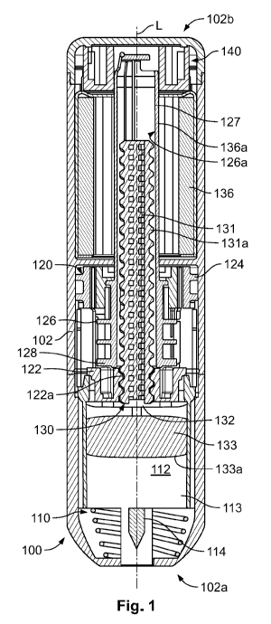
"slap" and "bump" generated by the excessive energy
can potentially cause catastrophic effects, such as breakage of the primary
container and drug product damage cause by shear
load. Furthermore, high force springs can produce undesirably high shear rates
on the drug product.
[0006] Further still, patients may experience a large variation in
injection times due to variations in characteristics of the
medicament. These variations can be disturbing to users, who may think
something is wrong with administration of the drug, and
thus they may end the injection before they receive the full dosage.
Variations in injection time may be caused by large drug
viscosity variation due to changes to the temperature of the drug, large
variations in friction between components in the device
(e.g., between a syringe barrel and a stopper), and so on.
SUMMARY
[0007] In accordance with a first aspect, a drug delivery device includes a
housing defining a shell having a proximal and a
distal end, a needle assembly at least partially disposed within the housing
at the proximal end, a drive assembly at least partially
disposed within the housing, and a damper mechanism at least partially
disposed within the housing at the distal end. The
housing further defines a longitudinal axis extending between the proximal end
and the distal end. The needle assembly includes
a syringe barrel containing a medicament and a needle or a cannula. The drive
assembly is operably coupled to the needle
assembly to urge the medicament through the needle or cannula. The damper
mechanism is operably coupled to the drive
assembly and the housing. Upon activating the drive assembly, the damper
mechanism dampens an effect thereof. In some
examples, the syringe barrel may be constructed from a polymeric material. The
medicament may have a viscosity of less than
approximately 10cP at approximately 21 degrees Celsius.
1
CA 03112355 2021-03-09
WO 2020/081479 PCT/US2019/056174
[0008] In this aspect, the damper mechanism includes a frame member, a damper
member operably coupled to the drive
assembly, a chamber formed between a portion of the frame member and the
damper member, and a damper fluid disposed
within the chamber. In some forms the frame member may be formed integrally
with the housing. Upon activating the drive
assembly of the drug delivery device, the frame member and the damper member
rotate relative to each other, and the damper
fluid exerts an opposing force on at least one of the frame member and the
damper member.
[0009] In some approaches, the drug delivery device may also include an
excess chamber fluidly coupled to the chamber. This
excess chamber is adapted to receive excess damper fluid. Further, in some
forms, the device may include a seal disposed near
the chamber to retain the damper fluid within the chamber. In some aspects,
the chamber is axially aligned with the longitudinal
axis. In other approaches, the chamber may be partially axially aligned with
the longitudinal axis and may be partially transversely
aligned therewith. In yet other approaches, the chamber may be transversely
aligned with the longitudinal axis.
[0010] In any of these examples, the drive assembly may include a plunger
assembly including a threaded plunger rod and a
plunger face, a plunger rod guide coupled to the plunger assembly, and a
torque spring coupled to the plunger rod guide. The
plunger face is disposed near the needle assembly and is movable along the
longitudinal axis of the housing. The plunger rod
guide guides rotational movement of the plunger assembly and is operably
coupled to one of the frame member or the damper
member. The torque spring exerts a force on the plunger rod guide that causes
the plunger rod guide to rotate. Rotation of the
plunger rod guide causes the plunger assembly to advance towards the proximal
end of the housing to urge the medicament
through the needle assembly. The plunger assembly may additionally include a
clearance of greater than approximately lOmm
between the threaded plunger rod and the plunger face. Further, the syringe
barrel may contain at least approximately 1mL of
medicament that has a viscosity of at least approximately 4cP. Other examples
are possible.
[0011] Further, in any of the foregoing examples, the damper mechanism can
exert an opposing force on the drive assembly,
or on at least one component operably coupled with the drive assembly.
[0012] In accordance with another aspect, a damper mechanism for a drug
delivery device includes a frame member, a
damper member operably coupled to a drive assembly of the drug delivery
device, a chamber formed between a portion of the
frame member and the damper member, and a damper fluid disposed within the
chamber. Upon activating the drug delivery
device to administer a medicament to a user, the frame member and the damper
member rotate relative to each other and the
damper fluid exerts an opposing force on at least one of the frame member and
the damper member.
[0013] In accordance with yet another aspect, an autoinjector includes a
housing defining a shell having a proximal end, a
distal end, and a longitudinal axis extending therebetween, a needle assembly
at least partially disposed within the housing at the
proximal end thereof, and a drive assembly at least partially disposed within
the housing. The needle assembly includes a
syringe barrel containing a medicament and a needle or a cannula. The drive
assembly is operably coupled to the needle
assembly to urge the medicament through the needle or cannula. The drive
assembly includes a plunger assembly having a
plunger rod and a plunger face being disposed near the needle assembly and
being moveable along the longitudinal axis of the
housing. The syringe barrel is adapted to contain at least approximately 1mL
of medicament having a viscosity of at least
approximately 4cP. The plunger rod and the plunger face have an initial
clearance of greater than approximately 10mm.
BRIEF DESCRIPTION OF THE DRAWINGS
[0014] The above needs are at least partially met through provision of the
torque driven drug delivery device described in the
following detailed description, particularly when studied in conjunction with
the drawings, wherein:
[0015] Fig. 1 illustrates a cross-sectional view of an example torque
driven drug delivery device having a damper mechanism
in accordance with various embodiments;
[0016] Fig. 2 illustrates a close-up cross-sectional view of the damper
mechanism of the example drug delivery device of Fig. 1
in accordance with various embodiments;
2
CA 03112355 2021-03-09
WO 2020/081479 PCT/US2019/056174
[0017] Fig. 3 illustrates a cross-sectional view of a second example drug
delivery device having a chamber for excessive
damper fluid in accordance with various embodiments;
[0018] Fig. 4 illustrates a cross-sectional view of a third example drug
delivery device having a damper fluid disposed between
disks of the damper mechanism in accordance with various embodiments;
[0019] Fig. 5 illustrates a cross-sectional view of a fourth example damper
mechanism of a drug delivery device in accordance
with various embodiments;
[0020] Figs. 6a and 6b illustrates cross-sectional views of a fifth example
damper mechanism of a drug delivery device in
accordance with various embodiments;
[0021] Fig. 7 illustrates a cross-sectional view of a sixth example damper
mechanism of a drug delivery device in accordance
with various embodiments;
[0022] Fig. 8 illustrates a cross-sectional view of a seventh example
damper mechanism of a drug delivery device in
accordance with various embodiments;
[0023] Figs. 9a-9c illustrate cross-sectional views of an eighth example
damper mechanism of a drug delivery device in
accordance with various embodiments;
[0024] Fig. 10 illustrates a cross-sectional view of a ninth example damper
mechanism of a drug delivery device in accordance
with various embodiments;
[0025] Fig. 11 illustrates a cross-sectional view of a tenth example damper
mechanism of a drug delivery device in accordance
with various embodiments;
[0026] Fig. 12 illustrates a cross-sectional view of a eleventh example
damper mechanism of a drug delivery device in
accordance with various embodiments;
[0027] Fig. 13 illustrates a cross-sectional view of a twelfth example
damper mechanism of a drug delivery device in
accordance with various embodiments;
[0028] Fig. 14 illustrates a cross-sectional view of a thirteenth example
damper mechanism of a drug delivery device in
accordance with various embodiments;
[0029] Fig. 15 illustrates a cross-sectional view of a fourteenth example
damper mechanism of a drug delivery device in
accordance with various embodiments;
[0030] Fig. 16 illustrates a cross-sectional view of a fifteenth example
damper mechanism of a drug delivery device in
accordance with various embodiments;
[0031] Fig. 17 illustrates a cross-sectional view of a sixteenth example
damper mechanism of a drug delivery device in
accordance with various embodiments;
[0032] Fig. 18 illustrates a cross-sectional view of a seventeenth example
damper mechanism of a drug delivery device in
accordance with various embodiments;
[0033] Fig. 19 illustrates a cross-sectional view of a eighteenth example
damper mechanism of a drug delivery device in
accordance with various embodiments;
[0034] Fig. 20 illustrates a cross-sectional view of a nineteenth example
damper mechanism of a drug delivery device in
accordance with various embodiments;
[0035] Fig. 21 illustrates a graph depicting shear stress as a function of
shear rate in accordance with various embodiments;
[0036] Fig. 22 illustrates a graph depicting apparent viscosity as a
function of shear rate in accordance with various
embodiments;
[0037] Fig. 23 illustrates a perspective view of an example drug delivery
device having a clearance between components in
accordance with various embodiments;
3
CA 03112355 2021-03-09
WO 2020/081479 PCT/US2019/056174
[0038] Fig. 24 illustrates an illustration of an example of the effect of a
damper mechanism on drug expulsion in accordance
with various embodiments;
[0039] Fig. 25 illustrates an illustration of an example of the effect of a
damper mechanism on drug expulsion in a low-friction
environment in accordance with various embodiments;
[0040] Fig. 26 illustrates an illustration of an example of the effect of a
damper mechanism on drug expulsion in a high-friction
environment in accordance with various embodiments; and
[0041] Fig. 27 illustrates example model calculations for a drug delivery
device in accordance with various embodiments.
[0042] Skilled artisans will appreciate that elements in the figures are
illustrated for simplicity and clarity and have not
necessarily been drawn to scale. For example, the dimensions and/or relative
positioning of some of the elements in the figures
may be exaggerated relative to other elements to help to improve understanding
of various embodiments of the present
invention. Also, common but well-understood elements that are useful or
necessary in a commercially feasible embodiment are
often not depicted in order to facilitate a less obstructed view of these
various embodiments. It will further be appreciated that
certain actions and/or steps may be described or depicted in a particular
order of occurrence while those skilled in the art will
understand that such specificity with respect to sequence is not actually
required. It will also be understood that the terms and
expressions used herein have the ordinary technical meaning as is accorded to
such terms and expressions by persons skilled in
the technical field as set forth above except where different specific
meanings have otherwise been set forth herein.
DETAILED DESCRIPTION
[0043] Generally speaking, pursuant to these various embodiments, a torque
driven injector includes a housing, a syringe
assembly containing a medicament to be injected into a user, and a rotatable
actuating assembly using a torque spring to cause
the medicament to be injected into the user. As the rotatable actuating
assembly rotates to cause the drug to be administered, a
fluid damper is used to provide a more consistent drug delivery time between
drugs of varying viscosities, as well as drugs that
may exhibit changes in viscosity based on different environmental changes
(e.g., varying temperatures).
[0044] Further, as the actuating mechanism rotates, the damper mechanism
can reduce or eliminates the "slap" or "bump" that
occurs when the plunger face first contacts the medicament and/or medicament
storage device. The damper mechanism may
also reduce the "jerk" or recoil when the mechanism is released. Accordingly,
a user will not feel this sudden movement during
the drug delivery process, and can comfortably and safely administer the
medicament. Further, the torque spring, which uses a
high number of turns, discussed in further detail below, may maintain near-
constant start and end torque as compared to
traditional springs and those with fewer turns. As a result, smaller
autoinjectors may be used, which can increase overall user
comfort. Additionally, the damper may reduce and/or eliminate the variation in
injection times and minimize the risk of the device
stalling. The damper may also provide for design freedom to target optimal
injection times for usability, and can potentially
eliminate the need to customize the device for different drug volumes.
[0045] Referring now to the drawings, and in particular to Figs. 1 and 2,
an example autoinjector 100 includes a housing 102
defining a shell, a needle assembly 110 at least partially disposed within the
shell 102, a drive assembly 120 also at least partially
disposed within the shell 102, and a damper mechanism 140 at least partially
disposed within the shell 102. The shell 102
includes a proximal end 102a, a distal end 102b, and defines a longitudinal
axis "L" extending between the proximal end 102a
and the distal end 102b.
[0046] The needle assembly 110 is generally disposed at or near the proximal
end 102a of the shell 102 and includes a
syringe barrel 112 containing a medicament 113 and a needle or a cannula 114.
The needle assembly 110 may include any
number of additional components such as, for example, a sidewall or sidewalls,
openings to allow the medicament 113 to pass to
the needle or cannula 114, return springs, shield members, filter members, and
the like, but for the sake of brevity, will not be
discussed in substantial detail. A portion of the syringe barrel 112 may be
open to accommodate a portion of the drive assembly
120, which will be described in further detail below. The syringe barrel 112
may be of any desired shape and/or size to
4
CA 03112355 2021-03-09
WO 2020/081479 PCT/US2019/056174
accommodate various quantities of medicament 113. In some examples, the
syringe barrel 112 can be constructed from a
polymeric material such as cyclic-olefin polymer (COP"), cyclic olefin
copolymer ("COC"), or a glass material. Other examples
are possible.
[0047] The drive assembly 120 may include a nut 122 positioned adjacent to
the syringe barrel 112, a trigger ring 124, a
plunger rod guide 126, a plunger rod assembly 130, and a drive mechanism in
the form of a torque or power spring 136.
Generally, portions of the drive assembly 120 may be fixedly coupled to the
shell 102 via any number of approaches. In some
arrangements, the nut 122 may be formed integrally with the shell 102 and may
include a threaded opening 122a. The trigger
ring 124 selectively engages the nut 122 and is configured to move in an axial
direction. In the illustrated example, the trigger ring
124 is in the form of a generally cylindrical ring having a generally circular
inner surface and any number of ledges, protrusions,
and grooves disposed around and/or inside the circumference of the ring. The
trigger ring 124 may be coupled to the housing
102 via any number of techniques.
[0048] The plunger rod guide 126 includes a rod portion 127 and a base portion
128 coupled thereto. The plunger rod guide
126 includes an opening 126a extending at least partially through the rod
portion 127 and the base portion 128. The base portion
128 can have any number of projections or tabs extending therefrom to define a
slidable engagement with the trigger ring 124.
[0049] The plunger rod assembly 130 includes a plunger rod 131, a washer 132,
and a plunger 133 that are moveable along
the longitudinal axis L of the housing 102. The plunger rod 131 has a threaded
portion 131a which is threadably coupled to the
plunger rod guide 126 and the threaded opening 122a of the nut 122. The washer
132 minimizes frictional losses between
rotation of the plunger rod 131 and the non-rotating plunger 133. In some
approaches, the washer 132 may also be used to
adjust the volume of medicament 113 by making the washer 132 thicker or
narrower. Accordingly, the washer 132 may be used
to accommodate a range of fill volumes of medicament 113 in the same device
100, thereby allowing for better control of the air
gap between the bottom of the washer 132 and the top of the plunger 133.
[0050] The rod portion 127 of the plunger rod guide 126 is coupled to the
plunger rod assembly 130 via any number of
approaches including, for example, via a splined connection or slotted
arrangement that allows for the plunger rod assembly 130
to be axially displaced relative to the plunger rod guide 126. As such, the
plunger rod guide 126 guides rotational movement of
the plunger rod assembly 130. The threaded portion 131a of the plunger rod
131, and correspondingly, the threaded opening
122a of the nut 122 may have a thread pitch suitable for any desired drug
delivery rate or force/torque combination when driven
by the drive mechanism 136. Relative rotation between the plunger rod 131 and
the nut 122 causes the plunger rod 131 to
advance axially towards the proximal end 102a of the housing 102. The plunger
133 has a top face 133a that is disposed near
the syringe barrel 112.
[0051] In the illustrated example, the drive mechanism 136 is in the form
of a power spring or a torque spring 136 having an
inner portion 136a coupled to the rod portion 127 of the plunger rod guide 126
via any known approach to exert a torque on the
plunger rod guide 126 that causes the plunger rod guide 126 to rotate about
axis L. In some examples, the torque spring 136
may have a high number of turns to provide an appropriate rotational travel
required to expel the medicament from the syringe
barrel 112, however, additional parameters of the spring design may influence
its torque output such as material properties and
any applied heat treatments. The pre-shaping of the torque spring 136 may also
impact its performance. As an example, in an
autoinjector, a pre-stressed spring may be preferred, because the pre-
stressing process generally increases torque output of the
spring by initial coiling the spring in an opposite direction of the intended
working condition, thereby causing permanent
deformation in the steel band. This deformation maximizes the stresses in the
material, thereby causing the torque to increase.
Such an increase in torque is beneficial to minimize device size and weight.
[0052] In some examples, the torque spring 136 may have between approximately
1 and approximately 30 turns in the wound
or loaded configuration, and preferably, approximately 12 turns. In some
examples, the total spring turns may be higher due to a
margin in both ends of the working range of approximately 20%, which may
result in the range being between approximately
CA 03112355 2021-03-09
WO 2020/081479 PCT/US2019/056174
1*1.4= 1.4 to 30*1.4 = 42. The dose mechanism turns are derived from the pitch
and the required travel length. As previously
stated, a smaller pitch is preferred due to requiring a low torque input and
activation force. Accordingly, the activation force also
will be lower. If a high axial force is not needed, the pitch can be raised
and require fewer spring turns, thus allowing the device to
be smaller. In some examples, the torque spring 136 may have a number of
initial or preload turns to have a usable torque. After
the preload turns, the torque spring 136 is further wound with working turns,
or turns that are used in the device during injection.
As a non-limiting example, the torque spring 136 may have approximately 2.5
preload turns and approximately 6 working turns.
As such, the total number of turns during assembly is approximately 8.5.
However, due to potentially large tolerances in the
angular positioning of spring terminations, the torque spring 136 may have an
initial play before reaching a solid state, and thus
may have a total of approximately 10 turns. Devices having different drug
volumes and viscosities may need a different average
torque generated from the torque spring 136 if the same dosing is desired. The
average torque output may be controlled by
adjusting the width of the band used for the torque spring 136 (e.g., the
axial length of the torque spring 136 when disposed in
the device), and maintaining the same number of working turns. Doing so may
allow different springs to be used with the same
configuration as the device and have similar injection times while the volume
and/or viscosity of the drug may be modified.
[0053] In some examples, the energy (EFLOW) required to expel the medicament
113 through a needle 114 is determined by
any combination of the drug volume, viscosity, needle flow path dimensions,
and the targeted dosing time. The energy
(ESPRI NG) that the torque spring 136 delivers may be determined by any
combination of the number of working turns (N) and
the average spring torque during the working turns (T). The energy delivered
by the spring may be calculated using the following
formula: ESPRI NG = 2*Tr*N*T. If frictional losses are excluded in the system,
the following relationship exists: EFLOW =
ESPRING = 2*Tr*N*T. Accordingly, the following relationship results:
EFLOW/(2*Tr)=N*T. In other words, to have sufficient energy
in the torque spring 136 to expel a given drug in a given volume through a
given needle in a given time, the product (N*T)
remains constant, and thus the higher torque may be converted to fewer working
turns.
[0054] The threaded interface between the plunger rod 131 and the nut 122
provides a translation between the input torque of
the torque spring 136 and the output axial force. By providing a torque spring
136 with a high turn count, it will have a lower
overall torque as well as a smaller change in start and end torque as compared
to a linear spring having comparable gearing
specifications or other torsion springs with few turns and a lower pitch.
Additionally, the threads of the plunger rod 131 and the
nut 122 can have a lower pitch due to the increase in turn count, while still
achieving the same linear motion of the plunger rod
assembly 130. If the thread pitch is low, a smaller input torque is necessary
to provide the same output force as a high pitch
thread and high torque spring. Accordingly, the high turn count (e.g., between
approximately 1 and approximately 30 turns), low
torque system described herein allows for reduced activation forces, as the
activation force is directly related to the input torque
that must be used to drive the plunger rod assembly 130. Additionally,
internal structural forces required to resist the torque from
the torque spring 136 during storage (e.g., prior to use) is reduced, thus
allowing for smaller injector designs to be used and for
less expensive raw materials to be used. Additionally, the threaded interface
between the plunger rod 131 and the nut 122 allows
the threaded plunger rod 131 to be adjusted to accommodate for varying
quantities of medicament stored in the syringe barrel
112. If necessary, the threaded plunger rod 131 may be initially installed at
a lower position in injectors 100 having lesser drug
product volumes disposed in the syringe barrel 112. Accordingly, the number of
unique components is reduced, and variation
management is simplified. The threaded plunger rod 131 may also be adjustably
installed at various depths during the
manufacturing and/or assembly process as needed.
[0055] The damper mechanism 140 is also at least partially disposed within the
housing 102 at the distal end 102b thereof.
The damper mechanism 140 is operably coupled to a portion of the drive
assembly 120 (e.g., the plunger rod guide 126) and the
housing 102. The damper mechanism 140 acts to dampen the effect of the torque
spring 136 on the drive assembly 120.
[0056] Generally, to activate the device, a user presses the device 100
against their skin, thereby causing the trigger ring 124
to disengage from the nut 122 and/or the plunger rod guide 126. Such
disengagement allows the plunger rod guide 126 to rotate
6
CA 03112355 2021-03-09
WO 2020/081479 PCT/US2019/056174
relative to the trigger ring 124. Because the torque spring 136 is in a wound
or compressed state, the torque spring 136 will begin
to unwind, thereby causing the plunger rod guide 126 to rotate. This rotation
in turn causes the plunger rod 131 to rotate, which,
due to the threaded interface between the plunger rod 131 and the nut 122,
causes the plunger rod 131 and the plunger 133 to
advance towards the proximal end 102a of the housing 102, thereby inserting
the needle or cannula 114 and administering the
medicament 113. As a non-limiting example, U.S. Provisional Application No.
62/719,367, filed on August 17, 2018, describes an
activation process and components of the drive assembly in further detail and
accordingly is incorporated by reference herein in
its entirety.
[0057] In the illustrated example of Figs. 1 and 2, the damper mechanism 140
includes a damper member 142, a frame
member 150, a chamber 160 formed between a portion of the damper member 142
and the frame member 150, and a damper
fluid 151 disposed within the chamber 160. The damper member 142 may be
coupled to the plunger rod guide 126 via any
number of approaches such as, for example, via a friction fit or threaded
engagement. The damper member 142 includes a body
143 having an inner surface 143a that defines a central opening or bore 144 to
accommodate a portion of the plunger rod guide
126, and further includes an outer surface 143b. The damper member 142 further
includes a winged portion 145 having an inner
surface 145a positioned away from the body 143 that faces the outer surface
143b thereof. A channel 146 is formed between the
outer surface 143b of the body 143 and the inner surface 145a of the winged
portion 145.
[0058] The frame member 150 is operably coupled to the housing 102. For
example, the frame member 150 may be in the
form of a cylindrical member defining a body 152 and a coupling portion 153 to
couple to the housing 102 via any number of
approaches such as, for example, adhesives, threaded, frictional connections,
and the like. In some examples, the frame
member 150 may be integrally formed with the distal end 102b of the housing
102.
[0059] The body 152 of the frame member 150 is adapted to be at least
partially inserted into the channel 146 of the damper
member 142. In the illustrated example, the frame member 150 further includes
a ledge 155 that engages (e.g., via a frictional
connection) the inner surface 145a of the winged portion 145. The chamber 160
is defined by the body 152 of the frame member
150 and the body 143 of the damper member 140. In some examples, the shell 102
may further define an end surface of the
chamber 160. The damper fluid 151 is disposed within this chamber 160.
[0060] As previously mentioned, relative rotation between components of the
damper mechanism 140 causes the damper fluid
151 to dampen this effect. Specifically, in this example, the damper member
140 rotates relative to the frame member 150 when
the plunger rod guide 122 rotates. A torque from the torque spring 136 exists
between the damper member 142 and the frame
150, thereby causing the system to accelerate from rest thus increasing speed.
During relative rotation, the damper fluid 151
experiences shear stress due to rotation of the damper member 142. In the
disclosed example, the damper fluid 151 thus exerts
an opposite acting reaction torque on the drive assembly 120 and, in
particular, the plunger rod guide 126 of the drive assembly
120. The speed of the drive assembly 120 increases until the opposite acting
damper torque has been built up to the same level
as the dosing torque and equilibrium is reached. This equilibrium occurs at a
specific speed and torque, and is dependent on a
number of factors such as, for example, geometry of the damper mechanism 140,
fluid properties of the damper fluid 151, and
the torque profile of the torque spring 136. Other examples are possible.
[0061] So configured, the damper mechanism 140 has a relatively simple design
using minimal parts to reduce assembly and
component costs and complexity. The damper mechanism 140 may be easily
assembled, filled, and tested on a separate
assembly line prior to being inserted into the device 100. In some examples,
it may also be of interest to have a robust and stable
damper mechanism 140. There are a number of parameters that may affect the
performance of the damper mechanism 140, and
by reducing the influence of these parameters may further increase the
stability of the damper mechanism 140. For example, and
as previously noted, a damper fluid 151 having a low variation in viscosity as
a function of temperature may be selected that have
shear thinning properties. The shear stress in the damper fluid 151 is
directly related to the damping torque. To obtain a relative
constant and predictable speed at a certain needed damping torque, it is
desired to have a change in input torque (and thereby
7
CA 03112355 2021-03-09
WO 2020/081479 PCT/US2019/056174
shear stress) cause a minimal change in shear rate. In some examples, and as
illustrated in Fig. 21 that depicts shear stress as a
function of shear rate for a damper fluid type "G", this may be best obtained
by having a design with a shear rate in the lower end,
as the variation in shear rate, y, at a given input torque interval is less in
this area. It is noted that the provided curve in Fig. 21,
and the values illustrated therein, only represent an example curve, and
accordingly other curves may be used. Fig. 22 illustrates
the apparent viscosity of the damper fluid type G. The shear thinning
properties can be seen by the decrease in the apparent
viscosity with the increase in shear rate.
[0062] Another parameter that may impact robustness and stability of the
damper mechanism include a large gap at a small
diameter. The shear rate level is designed to and influenced by the dimensions
of the damper mechanism 140. The size of the
gap that defines the chamber 160 impacts the shear rate. The art tolerances
can impact the size of the chamber 160 the least
amount if the nominal chamber 160 size is as large as possible and if the
chamber 160 is placed at the smallest possible
diameter.
[0063] Further, with brief reference to Fig. 23, the described damper
mechanism 140 may allow for significant clearances "C"
(e.g., approximately 10mm or more) between the plunger rod 131 and the plunger
133 without risking breakage of the syringe
barrel 112 or other components of the device 100 upon its activation and upon
impact between the plunger rod 131 and the
plunger 133. These devices may be adapted to extrude at least approximately
1m1 of medicament 113 having a viscosity of at
least approximately 4cP. Such large clearances advantageously reduce platform
complexity, inventory variations, and/or process
controls. The damper mechanism 140 also provides for a better user experience
when compared to devices without a damper
mechanism, where the impact shock, feel, and sound may startle a user.
[0064] In some examples, it may be beneficial for a substantial surface of
the damper member to be in contact with the
damper fluid. If the entire surface is not in contact with the damper fluid
due to under filling, the damping torque will be reduced.
Accordingly, Fig. 3 illustrates an alternative damper mechanism 240 for a drug
delivery device 200 that is less sensitive to the
filling precision. It will be appreciated that the drug delivery device 200
includes any number of similar components and/or
features as the drug delivery device 100, and thus includes similar two-digit
suffixes as used with reference to Figs. 1 and 2.
Accordingly, these components will not be discussed in substantial detail. In
the drug delivery device 200, the damper member
242 includes a body 243 having an inner surface 243a defining a central
opening or bore 244 to accommodate a portion of the
plunger rod guide 226, and further includes an outer surface 243b. The damper
member 242 includes a winged portion 245
having an inner surface 245a and a notch 245b. The damper member 242 further
defines a channel 246 between the outer
surface 243b of the body 243 and the inner surface 245a of the winged portion
245, and further includes an end cap portion 247.
[0065] In this example, the frame member 250 is integrally formed as an end
cap of the housing 202. The frame member
includes a generally cylindrical protrusion 252 having an inner surface 252a
and an outer surface 252b. The cylindrical protrusion
252 defines a tab 253 on the outer surface 252b. When the damper mechanism 240
is installed onto the drug delivery device
200, the cylindrical protrusion 252 is inserted into the channel 246. In this
configuration, the notch 245b engages the tab 253 to
restrict relative axial movement between the damper member 242 and the frame
member 250. Further, the concentric cylinders
are constrained to each other in a radial direction so part tolerances have
minimal influence on concentricity. However, relative
rotation between the damper member 242 and the frame member 250 is still
permitted. In this example, a U-shaped chamber
260 is formed between the protrusion 252, the body 243, and the end cap
portion 247 to accommodate the damper fluid 251. In
such a configuration, the chamber is partially axially and partially
transversely aligned with the longitudinal axis L. When
constructed, the channel 246 further defines an excess chamber 248 to
accommodate any excess damper fluid, which may be
used to selectively adjust the damping torque generated, or may simply be used
as a "spillover' region if more fluid than desired
was inadvertently supplied. In these examples, the damper mechanism 240 may
engage the housing 202 and/or the drive
assembly 220 as desired. Further, the damper mechanism 240 may be assembled to
the device 200 via an axial assembly
process.
8
CA 03112355 2021-03-09
WO 2020/081479 PCT/US2019/056174
[0066] In some examples, it may be desired to provide a sealing portion to
ensure the damper fluid stays in the desired
chamber in order to maintain a consistent damping torque. Such a seal may
create a resistance force between the frame and the
damper member, which in turn will create a resistance torque. This may be
undesirable during dosing as the power source (i.e.,
the torque spring), may need to be larger to overcome this extra resistance.
Accordingly, Fig. 4 illustrates an alternative drug
delivery device 300 having an alternative damper mechanism 340 that allows for
simple filling of the damper fluid, while
preventing the fluid from escaping. The drug delivery device 300 includes any
number of similar components and/or features as
the drug delivery devices 100 and 200, and thus includes similar two-digit
suffixes as used with reference to Figs. 1-3.
Accordingly, these components will not be discussed in substantial detail. In
the drug delivery device 300, the damper member
342 includes a body 343 and a disk portion 345 coupled to the body 343. The
disk portion 345 defines a first surface 345a and
includes any number of grooves 345b positioned along its length and terminates
at an outer end 345c. The frame member 350 is
also in the form of a generally cylindrical member having a generally disk-
like base 352 defining a first surface 352a and a
sidewall portion 353 that includes a tab 353a. The disk-like base 352 further
defines an opening 354.
[0067] In the illustrated example, any number of sealing members 347 are
disposed within or adjacent to the groove or
grooves 345b of the damper member 342. To assemble the damping mechanism, the
disk damper member 342 is inserted into
the opening 354 of the base 352, whereby the outer end 345c engages the tab
353a of the sidewall portion 353. As a result, a
chamber 360 is formed between the first surface 345a of the disk portion 345
and the first surface 352a of the base 352. In this
example, the chamber 360 is disposed in a transverse configuration, and is
sealed off via sealing member(s) 347. Such a damper
mechanism 340 can be assembled in the same power module in which no internal
rotary play exists, thereby reducing and/or
eliminating risk of the device 300 jerking at activation.
[0068] Turning to Fig. 5, an alternative damper mechanism 440 for a drug
delivery device 400 includes similar features as the
previously described damper mechanism 240. Accordingly, these features have
similar two-digit suffixes as those provided in Fig.
3, and thus will not be described in substantial detail. The damper mechanism
440 additionally includes a generally cylindrical
extension 447a extending from the end cap portion 247 that mates with an inner
cylinder 450a extending from the frame member
450. When the frame member 450 and the damper member 442 are coupled together,
relative rotation is still permitted, but the
concentric engagement between the extension 447a and the inner cylinder 450a
provides for increased centering of the
components, thereby resulting in a smaller variance of chamber 460 size.
[0069] Turning to Figs. 6a-8, alternative damper mechanisms are provided that
effectively double the damping surface by
creating two chambers that accommodate damping fluid on multiple sides of a
frame member. As a result, these damping
mechanisms may create approximately double the damper torque as compared to a
similar design having a single chamber.
Advantageously, these damper mechanisms may be made smaller compared to the
single chamber design if the same level of
damping torque is needed. These damping mechanisms include similar features as
those described with reference to Figs. 1-5,
and thus include similar two-digit suffixes. Accordingly, for the sake of
brevity, some of these components may not be described
in substantial detail.
[0070] As illustrated in Figs. 6a and 6b, the damper member 542 is generally U-
shaped and defines a channel 546 between an
inner sidewall 543a and an outer sidewall 543b. The damper member 542 may
additionally include a tab 544 extending from the
outer sidewall 543b, and a ledge 545 extending from the inner sidewall 543a.
The frame member 550 includes a base portion
552, a first generally cylindrical protrusion 553, and a second generally
cylindrical protrusion 554 that carries a notch 554a.
[0071] In operation, the ledge 545 of the damper member 542 frictionally
engages the plunger rod guide 526 to be rotatably
coupled thereto. The channel 546 is filled with damper fluid 551, and the
frame member 550 is coupled to the damper member
542 by inserting the first cylindrical protrusion 553 into the channel 546.
Upon doing so, the notch 554a engages the tab 544 to
secure the damper member 542 to the frame member 550. Further, the first
cylindrical protrusion 553 segments the channel 546
9
CA 03112355 2021-03-09
WO 2020/081479 PCT/US2019/056174
into a U-shaped chamber 560 whereby the damper fluid 551 surrounds the first
protrusion 553 and thus is disposed on both sides
thereof.
[0072] Fig. 7 illustrates a similar damper mechanism 640 as the mechanism
540 described in Figs. 6a and 6b, but additionally
includes a third generally cylindrical protrusion 655. This protrusion 655
engages the inner sidewall 643a to create an additional
channel 647 which acts as a fluid mitigation passage. In Fig. 8, the
components in the damper mechanism 740 are essentially
reversed. In other words, the frame member 750 defines a channel 757 between a
first sidewall 756 and a second sidewall 758,
while still including a cylindrical protrusion 754 that carries a notch 754a.
The damper member 742 includes a first protrusion 743,
a second protrusion 744 carrying a tab 744a, and a third protrusion 745
carrying a ledge 745a. The damper fluid 751 is disposed
within the channel 757, and the first protrusion 743 is inserted therein to
define the chamber 760 that surrounds the first
protrusion 743.
[0073] Figs. 9a-9c illustrate a similar damper mechanism 840 that allows
for easy filling of the damper fluid 851 into the
channel 857 of the frame member 850. The damper member 842 is then applied,
whereby the angled protrusion 843 wedges in
and distributes the damper fluid 851 to a single channel 860 between the first
protrusion 843 and the first and second sidewalls
856, 858. In this example, a protrusion 844a engages a notch 858a formed on
the second sidewall 858. Similarly, in Fig. 10, the
components of the damper mechanism 940 are essentially reversed. In other
words, like in Figs. 6a-7, the damper member 942
is generally U-shaped defining a channel 946 between an inner sidewall 943a
and an outer sidewall 943b. The damper member
942 further includes a secondary channel 947 extending from the outer sidewall
943b. The frame member 950 includes a base
portion 952, a first protrusion 953, a second protrusion 954, and a third
protrusion 956. The damper fluid 951 is inserted into the
channel 946, and the first protrusion 953 is inserted into the channel 946 to
define the chamber 960. In this example, the second
protrusion 954 is inserted into the second channel 947.
[0074] Figs. 11-20 illustrate alternative damper mechanisms having a three-
piece design. In these examples, the fluid path
may be sealed and/or prolonged to ensure fluid is contained within the chamber
or to allow the fluid to be easily fillable and
assembled. Additionally, these components may ensure concentricity between
damping surfaces. These damping mechanisms
include similar features as those described with reference to Figs. 1-10, and
thus include similar two-digit suffixes. Accordingly,
for the sake of brevity, some of these components may not be described in
substantial detail.
[0075] As illustrated in Fig. 11, the damper mechanism 1040 includes a first
damper member 1042, a frame member 1050,
and a second damper member 1062. The first damper member 1042 may be coupled
to the plunger rod guide (not illustrated) via
any number of approaches, and includes a body 1043 having an inner surface
1043a that defines a central opening or bore 1044
to accommodate a portion of the plunger rod guide and further defines an outer
surface 1043b. The first damper member 1042
also includes a winged portion 1045 having an inner surface 1045a positioned
away from the body 1043 that faces the outer
surface 1043b thereof. A channel 1046 is formed between the outer surface
1043b of the body 1043 and the inner surface 1045a
of the winged portion 1045.
[0076] The second damper member 1062 is in the form of a generally cylindrical
body 1063 having an inner surface 1063a
and an outer surface 1063b. The second damper member 1062 includes a ledge
1064 extending outwardly from the outer
surface 1063b. The second damper member 1062 is adapted to be at least
partially disposed within the channel 1046 and at
least partially surround the body 1043 of the first damper member 1042 to form
concentric cylinders. When in this configuration, a
chamber 1060 is formed between the outer surface 1043b of the first damper
member 1042 and the inner surface 1063a of the
second damper member 1062. This chamber 1060 accommodates the damper fluid
1051.
[0077] In this example, the frame member 1050 is integrally formed with the
distal end 1002b of the housing 1002 and
includes a base portion 1052 and a generally cylindrical protrusion 1053
extending therefrom. In operation, the frame member
1050 is placed in or near the channel 1046 and may engage the ledge 1064 of
the second damper member 1062 to retain the
second damper member in place. The frame member 1050 may include any number of
additional notches, tabs, and the like to
CA 03112355 2021-03-09
WO 2020/081479 PCT/US2019/056174
selectively engage the first and/or second damper members 1042, 1062. As a
result, the chamber 1060 may be defined by the
outer surface 1043b of the first damper member 1042, the inner surface 1063a
of the second damper member 1062, and the
base portion 1052 of the frame member 1050. Further, the first damper member
1042, the second damper member 1062, and
the frame member 1050 form three concentric cylinders, thereby limiting
relative movement (except for relative rotation)
therebetween. In some examples, the second damper member 1062 may be fixedly
coupled to the frame member 1050 (which
itself may be coupled to and/or integrally formed with the housing 1002) to
ensure that the second damper member 1062 remains
fixed while the first damper member 1042 rotates with the plunger rod guide.
Further, in some examples, the frame member 1050
may include a detent 1055 that engages with a groove 1045b on the winged
portion 1045 of the first damper member 1042 to
restrict relative axial movement.
[0078] The example damper mechanism 1140 illustrated in Fig. 12 is similar to
the damper mechanism 1040 (and thus, similar
features include similar two-digit suffixes), but differs in the placement of
the chamber 1160 and damper fluid 1151. Specifically,
the chamber 1160 is defined by the inner surface 1145a of the winged portion
1145, the outer surface 1163b of the body 1163 of
the second damper member 1162, and the base portion 1152 of the frame member
1150. In this example, the frame member
1150 includes a protrusion 1153 that inserts into a channel 1164 defined by
the second damper member 1162 to secure the
frame member 1150 to the second damper member 1162.
[0079] The example damper mechanism 1240 illustrated in Fig. 13 is similar to
the damper mechanism 1140 (and thus, similar
features include similar two-digit suffixes), but differs in that the frame
member 1250 includes a rotational locking protrusion 1253
in the form of a pin that engages a cylinder or bore 1264 defined by the
second damper member 1262. As such, relative rotation
between the frame member 1250 and the second damper member 1262 is restricted.
[0080] The example damper mechanism 1340 illustrated in Fig. 14 is similar to
the damper mechanism 1240 (and thus, similar
features include similar two-digit suffixes), but differs in that the damper
mechanism 1340 includes any number of sealing
components to seal the chamber 1360 in order to retain the damper fluid 1351
therein. Specifically, the frame member 1350
additionally includes a resilient finger portion 1356 adapted to form a seal
with the outer surface 1345b of the winged portion
1345 of the first damper member 1342. In this example, the winged portion 1345
has a generally tapered or wedge-like shape to
assist in properly seating the resilient finger 1356 against the outer surface
1345b thereof. Additionally, the first damper member
1342 an additional seal in the form of a bump or detent 1343 to abut against
the base portion 1352 of the frame member 1350.
[0081] The example damper mechanism 1440 illustrated in Fig. 15 is similar to
the previously-described three piece damper
mechanisms (and thus, similar features include similar two-digit suffixes),
but may advantageously provide for easy filling of the
chamber 1460 with damper fluid 1451 and further may include any number of
seating features to ensure the components are
properly aligned during installation. Specifically, a protrusion 1453 formed
by the base portion 1452 of the frame member 1450
may include a ledge 1453a that assists in properly seating the first damper
member 1442 against the frame member 1450. The
outer surface 1443a of the first damper member 1442 abuts against the ledge
1453a to ensure that the frame member 1450 is
properly concentrically arranged relative to the first damper member 1442 and
to additionally define the chamber 1460 as being
between the outer surface 1443a, the ledge 1453a, and the protrusion 1453. The
chamber 1460 may then be filled with damper
fluid 1451, and the second damper member 1462, in the form of a fitted or
press-fit lid, may be applied.
[0082] The second damper member 1462 includes a base portion 1463, a first
protrusion 1464, and a second protrusion 1465
that cooperate to define a channel 1466. When the second damper member 1462 is
installed, the first protrusion 1464 abuts
against the protrusion 1453 of the frame member 1450, and the second
protrusion 1465 additionally engages a ledge 1444 of the
first damper member 1442. As a result, the protrusion 1453 of the base member
1450 and the ledge 1444 of the first damper
member 1442 cooperate to guide placement of the second damper member 1462 to
reduce and/or eliminate relative
misalignment of these components. The second damper member 1462 also acts as a
seal to close off the chamber 1460.
11
CA 03112355 2021-03-09
WO 2020/081479 PCT/US2019/056174
[0083] The example damper mechanism 1540 illustrated in Fig. 16 is similar to
the previously-described three piece damper
mechanisms (and thus, similar features include similar two-digit suffixes),
but includes an alternative seating arrangement to
ensure the components are properly aligned during installation. The damper
mechanism 1540 includes a first damper member
1542 having a winged portion 1545 that defines a first surface 1545a, a tab
1545b, and a second surface or ledge 1545c. The
second damper member 1562 includes a cylinder or bore 1564 that couples to a
rotational locking protrusion 1553 carried by the
body portion 1552 of the frame member 1550. The second damper member 1562
additionally includes a facing surface 1562a
and a ledge 1566. The first surface 1545 of the winged portion 1545 is adapted
to abut the ledge 1566 of the second damper
member 1562, and the second surface 1545c of the winged portion 1545 is
adapted to abut the facing surface 1562a of the
second damper member 1562, thereby creating two points of contact or seating
surfaces. Accordingly, proper displacement of
the damper mechanism 1540 is further ensured.
[0084] Figs. 17 and 18 illustrate damper mechanisms 1640, 1740 that are
similar to the damper mechanisms 1240, 1340,
1440, and 1540 (and thus, similar features include similar two-digit
suffixes), but differ in that they use features of their respective
frame members 1650, 1750 as a seating surface. Specifically, in Fig. 17, the
first damper member 1642 includes a finger portion
1645 having a first ledge or surface 1645a, a second surface 1645b, a finger
1645c, and a protrusion 1645d extending from the
finger 1645c. The frame member 1650 includes a base portion 1652 carrying a
first protrusion 1653 which locks relative rotation,
and a second protrusion 1654 having an outer surface 1654a. The frame member
1650 further includes a tab 1656. The second
damper member 1662 includes a first surface 1662a, a channel or hole 1664, and
a ledge 1666 defining a surface 1666a. The
first protrusion 1653 of the frame member 1650 is inserted into the hole 1664
of the second damper member 1662 to prevent
relative rotation therebetween. Additionally, the surface 1666a of the ledge
1666 of the second damper member 1662 abuts
against the second protrusion 1654 of the frame member 1652. The first surface
1662a of the second damper member 1662
abuts against the first ledge 1645a of the finger portion 1645 of the first
damper member 1642, and the second surface 1645b of
the finger portion 1645 of the first damper member 1642 abuts against the
outer surface 1654a of the second protrusion 1654 of
the frame member 1650. Additionally, the finger 1645c of the finger portion
1645 engages the tab 1656 of the frame member
1656. Accordingly, multiple points of contact or seating surfaces are created
between the first damper member 1642, the frame
member 1650, and the second damper member 1662 to further ensure proper
displacement of the damper mechanism 1640. In
Fig. 18, the damper mechanism 1740 includes similar features, surfaces, and/or
ledges as the damper mechanism 1640
illustrated in Fig. 17, but the frame member 1750 additionally includes a
protrusion 1753 that carries a bump 1753a that engages
a channel 1745a of the finger portion 1745 of the first damper member 1742.
[0085] The example damper mechanisms illustrated in Figs. 19 and 20 are
similar to the previously-described damper
mechanisms (and thus, similar features include similar two-digit suffixes),
but include an additional sealing components. As
illustrated in Fig. 19, a sealing member 1870 is operably coupled (e.g., glued
or otherwise affixed) to the frame member 1850.
The sealing member 1870 can be molded using any number of conventional
approaches, and includes a number of resilient
sealing fingers 1872. These fingers 1872 are at least partially inserted into
the chamber 1860 to restrict the damper fluid 1851
from exiting the chamber 1860 in the event that a gap is formed between the
frame member 1850 and the first damper member
1842 and/or the second damper member 1862.
[0086] In Fig. 20, the resilient sealing fingers 1947 are carried by the
finger portion 1945 of the first damper member 1945.
These sealing fingers 1947 engage the frame member 1950 to ensure that damper
fluid 1951 does not leak into the remainder of
the device 1900.
[0087] Turning to Figs. 24-26, in some examples, it may be advantageous to
construct the syringe barrel 112 out of different
materials. Because of high friction variation in containers constructed from
some materials, there may be significant variance in
delivery times. The friction between the plunger and the syringe barrel may
result in substantial variation, especially when the
syringe is constructed from a polymeric material. As noted, the force required
for expelling the drug through the needle in a
12
CA 03112355 2021-03-09
WO 2020/081479 PCT/US2019/056174
specified time, which is directly linked to the axial plunger velocity, varies
with the viscosity of the drug. For high-viscosity drugs
(e.g., above 10-15 cP), the force requirement is high, and for low viscosity
drugs, the force requirement is low. The force is also
dependent on the velocity at which the drug is expelled. During dosing, an
equilibrium dosing velocity is achieved where the
velocity-dependent resistance in the system matches the input torque from the
power source. However, the range in which the
frictional forces vary in the system is constant regardless of the viscosity
of the drug. Consequently, the ratio between frictional
forces and drug expulsion force becomes high in the case of low-viscosity
drugs. Further, since a high variability in the frictional
forces is expected for polymer syringe barrels, the remaining torque from the
spring for expelling the drug can either be too high
or too low, resulting in too fast or too slow dosing time. This can result in
either unacceptably high variations in dosing times or
that the device stalls altogether.
[0088] The use of a damper mechanism addresses these inconsistencies by acting
as a buffer of excess torque. The velocity
of the dosing mechanism is the result of a mechanical equilibrium, in which
the friction in the system, the torque required to expel
the drug, and the torque acting on the mechanical damper is equal to the total
input torque from the power source. Because the
non-constant torques, the damper torque and the torque required the expel the
drug added, become more dominant than the
frictional forces, the variation in the frictional forces will have less
relative impact on the available torque for the expulsion, and
will therefore affect the velocity modestly. Generally, whenever the
resistance in the device increases ¨ be it during dosing due to
friction and component tolerances, or because of a higher drug viscosity ¨ the
velocity in the device decreases. However,
because of the velocity-dependence of the damper, an infinitesimal decrease in
velocity leads to a lower damping torque, which
in turn frees up available torque for overcoming the increased resistance.
[0089] As shown in Figs. 24-26, the variances between plunger friction, torque
required to expel the drug, and torque
absorbed by the damper are added to provide a nominal input torque
requirement. It is noted that the torque contributions in the
device are not limited to these provided terms. Because the damper dissipates
a substantial amount of torque, the spring is
dimensioned larger than if no damper was used. The velocity-dependent terms
(i.e., Tdamper and Tthig) dissipate the majority of the
energy in the device.
[0090] Because a small decrease in velocity corresponds to a large decrease
in damper torque (and vice-versa), only a minor
change in available torque for drug expulsion is observed. This is illustrated
in Figs. 25 and 26: in case 1, shown in Fig. 25, the
friction is in the lower end of the expected range, which results in the
viscous terms to increase in magnitude because of more
available torque, where the damper term will absorb the most torque while the
torque available for drug expulsion increases only
slightly. This results in only a slightly faster dosing time. Conversely, in
case 2 illustrated in Fig. 26, an increase friction results in
the damper torque decreasing substantially, while the available torque for
drug expulsion decreases only slightly, thus yielding
only a slightly longer dosing time. In devices without damper mechanisms, a
substantial percentage of the input torque is used for
overcoming the friction in the system. In variation in friction will directly
add or subtract substantially on the available torque for
the expulsion part. High fluctuations can therefore be expected at dosing
time.
[0091] Turning to Fig. 27, an example of the high sensitivity is
illustrated by model calculations. The first two columns A and B
illustrate the range of dosing times for a range of friction values where a
mechanical damper mechanism is used. Both the high
viscosity (column A) and low viscosity (column B) drug variant devices exhibit
a narrow variation in dosing time thanks to the
damper. For the variants without a damper (columns C and D), the variability
is similarly low for high viscosity drug variants. This
is attributed to the high proportion of the input torque spent on expelling
the drug relative to the torque used for overcoming the
constant friction. However, for the low viscosity drug variant (column D),
where no damper is used, the dosing time varies
dramatically with the friction variance. In addition to the high dosing time
sensitivity towards friction variability, in terms of a device
platform, any change in drug viscosity will substantially change the input
torque requirements if no damper is used. Therefore, in
order to achieve the desired window of doing times, a higher number of power
springs would be required. Having a damper, on
the other, introduces the buffering phenomenon at the expense of a slightly
larger spring.
13
CA 03112355 2021-03-09
WO 2020/081479 PCT/US2019/056174
[0092] Additionally, certain materials may impact these forces. For example,
when using a glass syringe, due to the
siloconization of the barrel and the stopper, there may be a lower glide
force, and lower variation of the glide force relative to
plastic syringes. When administering drugs having high viscosities, the
resistance of flow through the needle tends to be the
largest contributor to overall injection times. However, when administering
drugs having low viscosities and volumes, the glide
force (and its relative variability) can be a large contributor to the total
required force in the system.
[0093] So configured, the above damper designs can reduce the number of
required spring variants in an autoinjector
platform, can improve consistency of dose times for users, and can reduce
risks of syringe breakages. Because minor variations
in spring performance and/or drug viscosity can have a significant impact when
using low-viscosity drugs, the damper
mechanisms described herein slows all dose times, thereby requiring fewer
spring variants. When using drugs having high
viscosities, the damper mechanisms described herein have a greater effect on
the impact speed of the plunger rod, especially
when administering low volume drug products. The damper mechanism will reduce
the impact speed of the plunger rod to a safer
level to reduce the risk of damaging the syringe. The damper mechanisms
described herein require fewer parts, thereby assisting
in assembly and cost reduction. Additionally, the damper mechanisms described
do not rely on surface friction and relatively
complex moving mechanisms and thus further reduce system complexities.
[0094] The above description describes various assemblies, devices, and
methods for use with a drug delivery device. It
should be clear that the assemblies, drug delivery devices, or methods can
further comprise use of a medicament listed below
with the caveat that the following list should neither be considered to be all
inclusive nor limiting. The medicament will be
contained in a reservoir. In some instances, the reservoir is a primary
container that is either filled or pre-filled for treatment with
the medicament. The primary container can be a cartridge or a pre-filled
syringe.
[0095] For example, the drug delivery device or more specifically the
reservoir of the device may be filled with colony
stimulating factors, such as granulocyte colony-stimulating factor (G-CSF).
Such G-CSF agents include, but are not limited to,
Neupogen@ (filgrastim) and Neulasta@ (pegfilgrastim). In various other
embodiments, the drug delivery device may be used with
various pharmaceutical products, such as an erythropoiesis stimulating agent
(ESA), which may be in a liquid or a lyophilized
form. An ESA is any molecule that stimulates erythropoiesis, such as Epogen@
(epoetin alfa), Aranesp@ (darbepoetin alfa),
Dynepo@ (epoetin delta), Mircera@ (methyoxy polyethylene glycol-epoetin beta),
Hematide@, MRK-2578, INS-22, Retacrit@
(epoetin zeta), Neorecormon@ (epoetin beta), Silapo@ (epoetin zeta), Binocrit@
(epoetin alfa), epoetin alfa Hexal, Abseamed@
(epoetin alfa), Ratioepo@ (epoetin theta), Eporatio@ (epoetin theta), Biopoin@
(epoetin theta), epoetin alfa, epoetin beta, epoetin
zeta, epoetin theta, and epoetin delta, as well as the molecules or variants
or analogs thereof as disclosed in the following
patents or patent applications, each of which is herein incorporated by
reference in its entirety: U.S. Patent Nos. 4,703,008;
5,441,868; 5,547,933; 5,618,698; 5,621,080; 5,756,349; 5,767,078; 5,773,569;
5,955,422; 5,986,047; 6,583,272; 7,084,245; and
7,271,689; and PCT Publication Nos. WO 91/05867; WO 95/05465; WO 96/40772; WO
00/24893; WO 01/81405; and WO
2007/136752.
[0096] An ESA can be an erythropoiesis stimulating protein. As used herein,
"erythropoiesis stimulating protein" means any
protein that directly or indirectly causes activation of the erythropoietin
receptor, for example, by binding to and causing
dimerization of the receptor. Erythropoiesis stimulating proteins include
erythropoietin and variants, analogs, or derivatives
thereof that bind to and activate erythropoietin receptor; antibodies that
bind to erythropoietin receptor and activate the receptor;
or peptides that bind to and activate erythropoietin receptor. Erythropoiesis
stimulating proteins include, but are not limited to,
epoetin alfa, epoetin beta, epoetin delta, epoetin omega, epoetin iota,
epoetin zeta, and analogs thereof, pegylated
erythropoietin, carbamylated erythropoietin, mimetic peptides (including
EMP1/hematide), and mimetic antibodies. Exemplary
erythropoiesis stimulating proteins include erythropoietin, darbepoetin,
erythropoietin agonist variants, and peptides or antibodies
that bind and activate erythropoietin receptor (and include compounds reported
in U.S. Publication Nos. 2003/0215444 and
2006/0040858, the disclosures of each of which is incorporated herein by
reference in its entirety) as well as erythropoietin
14
CA 03112355 2021-03-09
WO 2020/081479 PCT/US2019/056174
molecules or variants or analogs thereof as disclosed in the following patents
or patent applications, which are each herein
incorporated by reference in its entirety: U.S. Patent Nos. 4,703,008;
5,441,868; 5,547,933; 5,618,698; 5,621,080; 5,756,349;
5,767,078; 5,773,569; 5,955,422; 5,830,851; 5,856,298; 5,986,047; 6,030,086;
6,310,078; 6,391,633; 6,583,272; 6,586,398;
6,900,292; 6,750,369; 7,030,226; 7,084,245; and 7,217,689; U.S. Publication
Nos. 2002/0155998; 2003/0077753;
2003/0082749; 2003/0143202; 2004/0009902; 2004/0071694; 2004/0091961;
2004/0143857; 2004/0157293; 2004/0175379;
2004/0175824; 2004/0229318; 2004/0248815; 2004/0266690; 2005/0019914;
2005/0026834; 2005/0096461; 2005/0107297;
2005/0107591; 2005/0124045; 2005/0124564; 2005/0137329; 2005/0142642;
2005/0143292; 2005/0153879; 2005/0158822;
2005/0158832; 2005/0170457; 2005/0181359; 2005/0181482; 2005/0192211;
2005/0202538; 2005/0227289; 2005/0244409;
2006/0088906; and 2006/0111279; and PCT Publication Nos. WO 91/05867; WO
95/05465; WO 99/66054; WO 00/24893; WO
01/81405; WO 00/61637; WO 01/36489; WO 02/014356; WO 02/19963; WO 02/20034; WO
02/49673; WO 02/085940; WO
03/029291; WO 2003/055526; WO 2003/084477; WO 2003/094858; WO 2004/002417; WO
2004/002424; WO 2004/009627;
WO 2004/024761; WO 2004/033651; WO 2004/035603; WO 2004/043382; WO
2004/101600; WO 2004/101606; WO
2004/101611; WO 2004/106373; WO 2004/018667; WO 2005/001025; WO 2005/001136;
WO 2005/021579; WO 2005/025606;
WO 2005/032460; WO 2005/051327; WO 2005/063808; WO 2005/063809; WO
2005/070451; WO 2005/081687; WO
2005/084711; WO 2005/103076; WO 2005/100403; WO 2005/092369; WO 2006/50959; WO
2006/02646; and WO 2006/29094.
[0097] Examples of other pharmaceutical products for use with the device
may include, but are not limited to, antibodies such
as Vectibix (panitumumab), Xgeva TM (denosumab) and Prolia TM (denosamab);
other biological agents such as Enbrel
(etanercept, TNF-receptor /Fc fusion protein, TNF blocker), Neulasta
(pegfilgrastim, pegylated filgastrim, pegylated G-CSF,
pegylated hu-Met-G-CSF), Neupogen (filgrastim , G-CSF, hu-MetG-CSF), and
Nplate (romiplostim); small molecule drugs
such as Sensipar (cinacalcet). The device may also be used with a therapeutic
antibody, a polypeptide, a protein or other
chemical, such as an iron, for example, ferumoxytol, iron dextrans, ferric
glyconate, and iron sucrose. The pharmaceutical
product may be in liquid form, or reconstituted from lyophilized form.
[0098] Among particular illustrative proteins are the specific proteins set
forth below, including fusions, fragments, analogs,
variants or derivatives thereof:
[0099] OPGL specific antibodies, peptibodies, and related proteins, and the
like (also referred to as RAN KL specific
antibodies, peptibodies and the like), including fully humanized and human
OPGL specific antibodies, particularly fully humanized
monoclonal antibodies, including but not limited to the antibodies described
in PCT Publication No. WO 03/002713, which is
incorporated herein in its entirety as to OPGL specific antibodies and
antibody related proteins, particularly those having the
sequences set forth therein, particularly, but not limited to, those denoted
therein: 9H7; 1882; 2D8; 2E11; 16E1; and 22B3,
including the OPGL specific antibodies having either the light chain of
sequence identification number:2 as set forth therein in
Figure 2 and/or the heavy chain of sequence identification number:4, as set
forth therein in Figure 4, each of which is individually
and specifically incorporated by reference herein in its entirety fully as
disclosed in the foregoing publication;
[00100] Myostatin binding proteins, peptibodies, and related proteins, and
the like, including myostatin specific peptibodies,
particularly those described in U.S. Publication No. 2004/0181033 and PCT
Publication No. WO 2004/058988, which are
incorporated by reference herein in their entirety particularly in parts
pertinent to myostatin specific peptibodies, including but not
limited to peptibodies of the mTN8-19 family, including those of sequence
identification numbers:305-351, including TN8-19-1
through TN8-19-40, TN8-19 con1 and TN8-19 c0n2; peptibodies of the mL2 family
of sequence identification numbers:357-383;
the mL15 family of sequence identification numbers:384-409; the mL17 family of
sequence identification numbers:410-438; the
mL20 family of sequence identification numbers:439-446; the mL21 family of
sequence identification numbers:447-452; the mL24
family of sequence identification numbers:453-454; and those of sequence
identification numbers:615-631, each of which is
individually and specifically incorporated by reference herein in their
entirety fully as disclosed in the foregoing publication;
CA 03112355 2021-03-09
WO 2020/081479 PCT/US2019/056174
[00101] IL-4 receptor specific antibodies, peptibodies, and related
proteins, and the like, particularly those that inhibit activities
mediated by binding of IL-4 and/or IL-13 to the receptor, including those
described in PCT Publication No. WO 2005/047331 or
PCT Application No. PCT/US2004/37242 and in U.S. Publication No. 2005/112694,
which are incorporated herein by reference in
their entirety particularly in parts pertinent to IL-4 receptor specific
antibodies, particularly such antibodies as are described
therein, particularly, and without limitation, those designated therein: L1H1;
L1H2; L1H3; L1H4; L1H5; L1H6; L1H7; L1H8; L1H9;
L1H10; L1H11; L2H1; L2H2; L2H3; L2H4; L2H5; L2H6; L2H7; L2H8; L2H9; L2H10;
L2H11; L2H12; L2H13; L2H14; L3H1; L4H1;
L5H1; L6H1, each of which is individually and specifically incorporated by
reference herein in its entirety fully as disclosed in the
foregoing publication;
[0100] Interleukin 1-receptor 1 ("IL1-R1") specific antibodies,
peptibodies, and related proteins, and the like, including but not
limited to those described in U.S. Publication No. 2004/097712, which is
incorporated herein by reference in its entirety in parts
pertinent to IL1-R1 specific binding proteins, monoclonal antibodies in
particular, especially, without limitation, those designated
therein: 15CA, 26F5, 27F2, 24E12, and 10H7, each of which is individually and
specifically incorporated by reference herein in its
entirety fully as disclosed in the aforementioned publication;
[0101] Ang2 specific antibodies, peptibodies, and related proteins, and the
like, including but not limited to those described in
PCT Publication No. WO 03/057134 and U.S. Publication No. 2003/0229023, each
of which is incorporated herein by reference
in its entirety particularly in parts pertinent to Ang2 specific antibodies
and peptibodies and the like, especially those of
sequences described therein and including but not limited to: Li (N); Li (N)
WT; Li (N) 1K WT; 2xL1(N); 2xL1(N) WT; Con4 (N),
Con4 (N) 1K WT, 2xCon4 (N) 1K; L1C; L1C 1K; 2xL1C; Con4C; Con4C 1K; 2xCon4C
1K; Con4-L1 (N); Con4-L1C; TN-12-9 (N);
C17 (N); TN8-8(N); TN8-14 (N); Con 1 (N), also including anti-Ang 2 antibodies
and formulations such as those described in PCT
Publication No. WO 2003/030833 which is incorporated herein by reference in
its entirety as to the same, particularly Ab526;
Ab528; Ab531; Ab533; Ab535; Ab536; Ab537; Ab540; Ab543; Ab544; Ab545; Ab546;
A551; Ab553; Ab555; Ab558; Ab559;
Ab565; AbF1AbFD; AbFE; AbFJ; AbFK; AbG1D4; AbGC1E8; AbH1C12; AblA1; AblF;
AbIK, AblP; and AblP, in their various
permutations as described therein, each of which is individually and
specifically incorporated by reference herein in its entirety
fully as disclosed in the foregoing publication;
[0102] NGF specific antibodies, peptibodies, and related proteins, and the
like including, in particular, but not limited to those
described in U.S. Publication No. 2005/0074821 and U.S. Patent No. 6,919,426,
which are incorporated herein by reference in
their entirety particularly as to NGF-specific antibodies and related proteins
in this regard, including in particular, but not limited
to, the NGF-specific antibodies therein designated 4D4, 4G6, 6H9, 7H2, 14D10
and 14D11, each of which is individually and
specifically incorporated by reference herein in its entirety fully as
disclosed in the foregoing publication;
[0103] CD22 specific antibodies, peptibodies, and related proteins, and the
like, such as those described in U.S. Patent No.
5,789,554, which is incorporated herein by reference in its entirety as to
CD22 specific antibodies and related proteins,
particularly human CD22 specific antibodies, such as but not limited to
humanized and fully human antibodies, including but not
limited to humanized and fully human monoclonal antibodies, particularly
including but not limited to human CD22 specific IgG
antibodies, such as, for instance, a dimer of a human-mouse monoclonal hLL2
gamma-chain disulfide linked to a human-mouse
monoclonal hLL2 kappa-chain, including, but limited to, for example, the human
CD22 specific fully humanized antibody in
Epratuzumab, CAS registry number 501423-23-0;
[0104] IGF-1 receptor specific antibodies, peptibodies, and related
proteins, and the like, such as those described in PCT
Publication No. WO 06/069202, which is incorporated herein by reference in its
entirety as to IGF-1 receptor specific antibodies
and related proteins, including but not limited to the IGF-1 specific
antibodies therein designated Li Hi, L2H2, L3H3, L4H4, L5H5,
L6H6, L7H7, L8H8, L9H9, L10H10, L11H11, L12H12, L13H13, L14H14, L15H15,
L16H16, L17H17, L18H18, L19H19, L20H20,
L21H21, L22H22, L23H23, L24H24, L25H25, L26H26, L27H27, L28H28, L29H29,
L30H30, L31H31, L32H32, L33H33, L34H34,
L35H35, L36H36, L37H37, L38H38, L39H39, L40H40, L41H41, L42H42, L43H43,
L44H44, L45H45, L46H46, L47H47, L48H48,
16
CA 03112355 2021-03-09
WO 2020/081479 PCT/US2019/056174
L49H49, L50H50, L51H51, L52H52, and IGF-1R-binding fragments and derivatives
thereof, each of which is individually and
specifically incorporated by reference herein in its entirety fully as
disclosed in the foregoing publication;
[0105] Also among non-limiting examples of anti-IGF-1R antibodies for use in
the methods and compositions of the present
invention are each and all of those described in:
(i) U.S. Publication No. 2006/0040358 (published February 23, 2006),
2005/0008642 (published January 13, 2005),
2004/0228859 (published November 18, 2004), including but not limited to, for
instance, antibody 1A (DSMZ Deposit No. DSM
ACC 2586), antibody 8 (DSMZ Deposit No. DSM ACC 2589), antibody 23 (DSMZ
Deposit No. DSM ACC 2588) and antibody 18
as described therein;
(ii) PCT Publication No. WO 06/138729 (published December 28, 2006) and WO
05/016970 (published February 24,
2005), and Lu et al. (2004), J. Biol. Chem. 279:2856-2865, including but not
limited to antibodies 2F8, Al2, and IMC-Al2 as
described therein;
(iii) PCT Publication No. WO 07/012614 (published February 1, 2007), WO
07/000328 (published January 4, 2007),
WO 06/013472 (published February 9, 2006), WO 05/058967 (published June 30,
2005), and WO 03/059951 (published July 24,
2003);
(iv) U.S. Publication No. 2005/0084906 (published April 21, 2005), including
but not limited to antibody 7C10, chimaeric
antibody C7C10, antibody h7C10, antibody 7H2M, chimaeric antibody *7C10,
antibody GM 607, humanized antibody 7C10
version 1, humanized antibody 7C10 version 2, humanized antibody 7C10 version
3, and antibody 7H2HM, as described therein;
(v) U.S. Publication Nos. 2005/0249728 (published November 10, 2005),
2005/0186203 (published August 25, 2005),
2004/0265307 (published December 30, 2004), and 2003/0235582 (published
December 25, 2003) and Maloney et al. (2003),
Cancer Res. 63:5073-5083, including but not limited to antibody EM164,
resurfaced EM164, humanized EM164, huEM164 v1.0,
huEM164 v1.1, huEM164 v1.2, and huEM164 v1.3 as described therein;
(vi) U.S. Patent No. 7,037,498 (issued May 2, 2006), U.S. Publication Nos.
2005/0244408 (published November 30,
2005) and 2004/0086503 (published May 6, 2004), and Cohen, et al. (2005),
Clinical Cancer Res. 11:2063-2073, e.g., antibody
CP-751,871, including but not limited to each of the antibodies produced by
the hybridomas having the ATCC accession numbers
PTA-2792, PTA-2788, PTA-2790, PTA-2791, PTA-2789, PTA-2793, and antibodies
2.12.1, 2.13.2, 2.14.3, 3.1.1, 4.9.2, and
4.17.3, as described therein;
(vii) U.S. Publication Nos. 2005/0136063 (published June 23, 2005) and
2004/0018191 (published January 29, 2004),
including but not limited to antibody 19D12 and an antibody comprising a heavy
chain encoded by a polynucleotide in plasmid
15H12/19D12 HCA (y4), deposited at the ATCC under number PTA-5214, and a light
chain encoded by a polynucleotide in
plasmid 15H12/19D12 LCF (k), deposited at the ATCC under number PTA-5220, as
described therein; and
(viii) U.S. Publication No. 2004/0202655 (published October 14, 2004),
including but not limited to antibodies PINT-
6A1, PINT-7A2, PINT-7A4, PINT-7A5, PINT-7A6, PINT-8A1, PINT-9A2, PINT-11A1,
PINT-11A2, PINT-11A3, PINT-11A4, PINT-
11A5, PINT-11A7, PINT-11Al2, PINT-12A1, PINT-12A2, PINT-12A3, PINT-12A4, and
PINT-12A5, as described therein; each
and all of which are herein incorporated by reference in their entireties,
particularly as to the aforementioned antibodies,
peptibodies, and related proteins and the like that target IGF-1 receptors;
[0106] B-7 related protein 1 specific antibodies, peptibodies, related
proteins and the like ("B7RP-1," also is referred to in the
literature as B7H2, ICOSL, B7h, and CD275), particularly B7RP-specific fully
human monoclonal IgG2 antibodies, particularly
fully human IgG2 monoclonal antibody that binds an epitope in the first
immunoglobulin-like domain of B7RP-1, especially those
that inhibit the interaction of B7RP-1 with its natural receptor, ICOS, on
activated T cells in particular, especially, in all of the
foregoing regards, those disclosed in U.S. Publication No. 2008/0166352 and
PCT Publication No. WO 07/011941, which are
incorporated herein by reference in their entireties as to such antibodies and
related proteins, including but not limited to
antibodies designated therein as follow: 16H (having light chain variable and
heavy chain variable sequences sequence
17
CA 03112355 2021-03-09
WO 2020/081479 PCT/US2019/056174
identification number:1 and sequence identification number:7 respectively
therein); 5D (having light chain variable and heavy
chain variable sequences sequence identification number:2 and sequence
identification number:9 respectively therein); 2H
(having light chain variable and heavy chain variable sequences sequence
identification number:3 and sequence identification
number:10 respectively therein); 43H (having light chain variable and heavy
chain variable sequences sequence identification
number:6 and sequence identification number:14 respectively therein); 41H
(having light chain variable and heavy chain variable
sequences sequence identification number:5 and sequence identification
number:13 respectively therein); and 15H (having light
chain variable and heavy chain variable sequences sequence identification
number:4 and sequence identification number:12
respectively therein), each of which is individually and specifically
incorporated by reference herein in its entirety fully as
disclosed in the foregoing publication;
[0107] IL-15 specific antibodies, peptibodies, and related proteins, and
the like, such as, in particular, humanized monoclonal
antibodies, particularly antibodies such as those disclosed in U.S.
Publication Nos. 2003/0138421; 2003/023586; and
2004/0071702; and U.S. Patent No. 7,153,507, each of which is incorporated
herein by reference in its entirety as to IL-15
specific antibodies and related proteins, including peptibodies, including
particularly, for instance, but not limited to, HuMax IL-15
antibodies and related proteins, such as, for instance, 14687;
[0108] I FN gamma specific antibodies, peptibodies, and related proteins
and the like, especially human IFN gamma specific
antibodies, particularly fully human anti-I FN gamma antibodies, such as, for
instance, those described in U.S. Publication No.
2005/0004353, which is incorporated herein by reference in its entirety as to
I FN gamma specific antibodies, particularly, for
example, the antibodies therein designated 1118; 1118*, 1119; 1121; and 1121*.
The entire sequences of the heavy and light
chains of each of these antibodies, as well as the sequences of their heavy
and light chain variable regions and complementarity
determining regions, are each individually and specifically incorporated by
reference herein in its entirety fully as disclosed in the
foregoing publication and in Thakur et al. (1999), Mol. lmmunol. 36:1107-1115.
In addition, description of the properties of these
antibodies provided in the foregoing publication is also incorporated by
reference herein in its entirety. Specific antibodies include
those having the heavy chain of sequence identification number:17 and the
light chain of sequence identification number:18;
those having the heavy chain variable region of sequence identification
number:6 and the light chain variable region of sequence
identification number:8; those having the heavy chain of sequence
identification number:19 and the light chain of sequence
identification number:20; those having the heavy chain variable region of
sequence identification number:10 and the light chain
variable region of sequence identification number:12; those having the heavy
chain of sequence identification number:32 and the
light chain of sequence identification number:20; those having the heavy chain
variable region of sequence identification
number:30 and the light chain variable region of sequence identification
number:12; those having the heavy chain sequence of
sequence identification number:21 and the light chain sequence of sequence
identification number:22; those having the heavy
chain variable region of sequence identification number:14 and the light chain
variable region of sequence identification
number:16; those having the heavy chain of sequence identification number:21
and the light chain of sequence identification
number:33; and those having the heavy chain variable region of sequence
identification number:14 and the light chain variable
region of sequence identification number:31, as disclosed in the foregoing
publication. A specific antibody contemplated is
antibody 1119 as disclosed in the foregoing U.S. publication and having a
complete heavy chain of sequence identification
number:17 as disclosed therein and having a complete light chain of sequence
identification number:18 as disclosed therein;
[0109] TALL-1 specific antibodies, peptibodies, and the related proteins,
and the like, and other TALL specific binding proteins,
such as those described in U.S. Publication Nos. 2003/0195156 and
2006/0135431, each of which is incorporated herein by
reference in its entirety as to TALL-1 binding proteins, particularly the
molecules of Tables 4 and 5B, each of which is individually
and specifically incorporated by reference herein in its entirety fully as
disclosed in the foregoing publications;
18
CA 03112355 2021-03-09
WO 2020/081479 PCT/US2019/056174
[0110] Parathyroid hormone ("PTH") specific antibodies, peptibodies, and
related proteins, and the like, such as those
described in U.S. Patent No. 6,756,480, which is incorporated herein by
reference in its entirety, particularly in parts pertinent to
proteins that bind PTH;
[0111] Thrombopoietin receptor ("TPO-R") specific antibodies, peptibodies,
and related proteins, and the like, such as those
described in U.S. Patent No. 6,835,809, which is herein incorporated by
reference in its entirety, particularly in parts pertinent to
proteins that bind TPO-R;
[0112] Hepatocyte growth factor ("HGF") specific antibodies, peptibodies,
and related proteins, and the like, including those
that target the HGF/SF:cMet axis (HGF/SF:c-Met), such as the fully human
monoclonal antibodies that neutralize hepatocyte
growth factor/scatter (HGF/SF) described in U.S. Publication No. 2005/0118643
and PCT Publication No. WO 2005/017107,
huL2G7 described in U.S. Patent No. 7,220,410 and 0A-5d5 described in U.S.
Patent Nos. 5,686,292 and 6,468,529 and in PCT
Publication No. WO 96/38557, each of which is incorporated herein by reference
in its entirety, particularly in parts pertinent to
proteins that bind HGF;
[0113] TRAIL-R2 specific antibodies, peptibodies, related proteins and the
like, such as those described in U.S. Patent No.
7,521,048, which is herein incorporated by reference in its entirety,
particularly in parts pertinent to proteins that bind TRAIL-R2;
[0114] Activin A specific antibodies, peptibodies, related proteins, and
the like, including but not limited to those described in
U.S. Publication No. 2009/0234106, which is herein incorporated by reference
in its entirety, particularly in parts pertinent to
proteins that bind Activin A;
[0115] TGF-beta specific antibodies, peptibodies, related proteins, and the
like, including but not limited to those described in
U.S. Patent No. 6,803,453 and U.S. Publication No. 2007/0110747, each of which
is herein incorporated by reference in its
entirety, particularly in parts pertinent to proteins that bind TGF-beta;
[0116] Amyloid-beta protein specific antibodies, peptibodies, related
proteins, and the like, including but not limited to those
described in PCT Publication No. WO 2006/081171, which is herein incorporated
by reference in its entirety, particularly in parts
pertinent to proteins that bind amyloid-beta proteins. One antibody
contemplated is an antibody having a heavy chain variable
region comprising sequence identification number:8 and a light chain variable
region having sequence identification number:6 as
disclosed in the foregoing publication;
[0117] c-Kit specific antibodies, peptibodies, related proteins, and the
like, including but not limited to those described in U.S.
Publication No. 2007/0253951, which is incorporated herein by reference in its
entirety, particularly in parts pertinent to proteins
that bind c-Kit and/or other stem cell factor receptors;
[0118] OX4OL specific antibodies, peptibodies, related proteins, and the
like, including but not limited to those described in
U.S. Publication No. 2006/0002929, which is incorporated herein by reference
in its entirety, particularly in parts pertinent to
proteins that bind OX4OL and/or other ligands of the 0X40 receptor; and
[0119] Other exemplary proteins, including Activase@ (alteplase, tPA);
Aranesp@ (darbepoetin alfa); Epogen@ (epoetin alfa, or
erythropoietin); GLP-1, Avonex@ (interferon beta-la); Beocar (tositumomab,
anti-CD22 monoclonal antibody); Betaseron@
(interferon-beta); Campath@ (alemtuzumab, anti-CD52 monoclonal antibody);
Dynepo@ (epoetin delta); Velcade@ (bortezomib);
MLN0002 (anti- a4I37 mAb); MLN1202 (anti-CCR2 chemokine receptor mAb); Enbrel@
(etanercept, TNF-receptor /Fc fusion
protein, TNF blocker); Eprex@ (epoetin alfa); Erbitux@ (cetuximab, anti-EGFR /
HER1 / c-ErbB-1); Genotropin@ (somatropin,
Human Growth Hormone); Herceptin@ (trastuzumab, anti-HER2/neu (erbB2) receptor
mAb); Humatrope@ (somatropin, Human
Growth Hormone); Humira@ (adalimumab); insulin in solution; Infergen
(interferon alfacon-1); Natrecor@ (nesiritide;
recombinant human B-type natriuretic peptide (hBNP); Kineret@ (anakinra);
Leukine@ (sargamostim, rhuGM-CSF);
LymphoCide@ (epratuzumab, anti-CD22 mAb); Benlysta TM (lymphostat B,
belimumab, anti-BlyS mAb); Metalyse@ (tenecteplase,
t-PA analog); Mircera@ (methoxy polyethylene glycol-epoetin beta); Mylotarg@
(gemtuzumab ozogamicin); Raptiva@
(efalizumab); Cimzia@ (certolizumab pegol, CDP 870); Soliris TM (eculizumab);
pexelizumab (anti-05 complement); Numax@
19
CA 03112355 2021-03-09
WO 2020/081479 PCT/US2019/056174
(MEDI-524); Lucentis@ (ranibizumab); Panorex@ (17-1A, edrecolomab); Trabio@
(lerdelimumab); TheraCim hR3 (nimotuzumab);
Omnitarg (pertuzumab, 2C4); Osidem (IDM-1); OvaRex (B43.13); Nuvion
(visilizumab); cantuzumab mertansine (huC242-
DM1); NeoRecormon (epoetin beta); Neumega (oprelvekin, human interleukin-
11); Neulasta (pegylated filgastrim, pegylated
G-CSF, pegylated hu-Met-G-CSF); Neupogen (filgrastim , G-CSF, hu-MetG-CSF);
Orthoclone OKT3 (muromonab-CD3, anti-
CD3 monoclonal antibody); Procrit (epoetin alfa); Remicade (infliximab, anti-
TNFa monoclonal antibody); Reopro
(abciximab, anti-GP lib/Ilia receptor monoclonal antibody); Actemra (anti-1L6
Receptor mAb); Avastin (bevacizumab), HuMax-
CD4 (zanolimumab); Rituxan (rituximab, anti-CD20 mAb); Tarceva (erlotinib);
Roferon-A0-(interferon alfa-2a); Simulect
(basiliximab); Prexige (lumiracoxib); Synagis (palivizumab); 14687-CHO (anti-
1L15 antibody, see U.S. Patent No. 7,153,507);
Tysabri (natalizumab, anti-a4integrin mAb); Valortim (MDX-1303, anti-B.
anthracis protective antigen mAb); ABthrax TM ;
Vectibix0 (panitumumab); Xolair (omalizumab); ETI211 (anti-MRSA mAb); IL-1
trap (the Fc portion of human IgG1 and the
extracellular domains of both IL-1 receptor components (the Typel receptor and
receptor accessory protein)); VEGF trap (Ig
domains of VEGFR1 fused to IgG1 Fc); Zenapax (daclizumab); Zenapax
(daclizumab, anti-IL-2Ra mAb); Zevalin
(ibritumomab tiuxetan); Zetia (ezetimibe); Orencia (atacicept, TACI-Ig);
anti-CD80 monoclonal antibody (galiximab); anti-CD23
mAb (lumiliximab); BR2-Fc (huBR3 / huFc fusion protein, soluble BAFF
antagonist); CNTO 148 (golimumab, anti-TNFa mAb);
HGS-ETR1 (mapatumumab; human anti-TRAIL Receptor-1 mAb); HuMax-CD20
(ocrelizumab, anti-CD20 human mAb); HuMax-
EGFR (zalutumumab); M200 (volociximab, anti-a581 integrin mAb); MDX-010
(ipilimumab, anti-CTLA-4 mAb and VEGFR-1
(IMC-18F1); anti-BR3 mAb; anti-C. difficile Toxin A and Toxin B C mAbs MDX-066
(CDA-1) and MDX-1388); anti-CD22 dsFv-
PE38 conjugates (CAT-3888 and CAT-8015); anti-CD25 mAb (HuMax-TAC); anti-CD3
mAb (NI-0401); adecatumumab; anti-
CD30 mAb (MDX-060); MDX-1333 (anti-IFNAR); anti-CD38 mAb (HuMax CD38); anti-
CD4OL mAb; anti-Cripto mAb; anti-CTGF
Idiopathic Pulmonary Fibrosis Phase 1 Fibrogen (FG-3019); anti-CTLA4 mAb; anti-
eotaxin1 mAb (CAT-213); anti-FGF8 mAb;
anti-ganglioside GD2 mAb; anti-ganglioside GM2 mAb; anti-GDF-8 human mAb (MY0-
029); anti-GM-CSF Receptor mAb (CAM-
3001); anti-HepC mAb (HuMax HepC); anti-IFNa mAb (MEDI-545, MDX-1103); anti-
IGF1R mAb; anti-IGF-1R mAb (HuMax-
Inflam); anti-IL12 mAb (ABT-874); anti-IL12/1L23 mAb (CNTO 1275); anti-IL13
mAb (CAT-354); anti-IL2Ra mAb (HuMax-TAC);
anti-1L5 Receptor mAb; anti-integrin receptors mAb (MDX-018, CNTO 95); anti-
IP10 Ulcerative Colitis mAb (MDX-1100); anti-LLY
antibody; BMS-66513; anti-Mannose Receptor/hCG8 mAb (MDX-1307); anti-
mesothelin dsFv-PE38 conjugate (CAT-5001); anti-
PD1mAb (MDX-1106 (ONO-4538)); anti-PDGFRa antibody (IMC-3G3); anti-TGFR mAb
(GC-1008); anti-TRAIL Receptor-2
human mAb (HGS-ETR2); anti-TWEAK mAb; anti-VEGFR/Flt-1 mAb; anti-ZP3 mAb
(HuMax-ZP3); NVS Antibody #1; and NVS
Antibody #2.
[0120] Also included can be a sclerostin antibody, such as but not limited to
romosozumab, blosozumab, or BPS 804
(Novartis). Further included can be therapeutics such as rilotumumab,
bixalomer, trebananib, ganitumab, conatumumab,
motesanib diphosphate, brodalumab, vidupiprant, panitumumab, denosumab,
NPLATE, PROLIA, VECTIBIX or XGEVA.
Additionally, included in the device can be a monoclonal antibody (IgG) that
binds human Proprotein Convertase Subtilisin/Kexin
Type 9 (PCSK9). Such PCSK9 specific antibodies include, but are not limited
to, Repatha (evolocumab) and Praluent
(alirocumab), as well as molecules, variants, analogs or derivatives thereof
as disclosed in the following patents or patent
applications, each of which is herein incorporated by reference in its
entirety for all purposes: U.S. Patent No. 8,030,547, U.S.
Publication No. 2013/0064825, W02008/057457, W02008/057458, W02008/057459,
W02008/063382, W02008/133647,
W02009/100297, W02009/100318, W02011/037791, W02011/053759, W02011/053783,
W02008/125623, W02011/072263,
W02009/055783, W02012/0544438, W02010/029513, W02011/111007, W02010/077854,
W02012/088313, W02012/101251,
W02012/101252, W02012/101253, W02012/109530, and W02001/031007.
[0121] Also included can be talimogene laherparepvec or another oncolytic HSV
for the treatment of melanoma or other
cancers. Examples of oncolytic HSV include, but are not limited to talimogene
laherparepvec (U.S. Patent Nos. 7,223,593 and
CA 03112355 2021-03-09
WO 2020/081479 PCT/US2019/056174
7,537,924); OncoVEXGALV/CD (U.S. Pat. No. 7,981,669); OrienX010 (Lei et al.
(2013), World J. Gastroenterol., 19:5138-5143);
G207, 1716; NV1020; NV12023; NV1034 and NV1042 (Vargehes et al. (2002), Cancer
Gene Ther., 9(12):967-978).
[0122] Also included are TIMPs. TIMPs are endogenous tissue inhibitors of
metalloproteinases (TIMPs) and are important in
many natural processes. TI MP-3 is expressed by various cells or and is
present in the extracellular matrix; it inhibits all the major
cartilage-degrading metalloproteases, and may play a role in role in many
degradative diseases of connective tissue, including
rheumatoid arthritis and osteoarthritis, as well as in cancer and
cardiovascular conditions. The amino acid sequence of TI MP-3,
and the nucleic acid sequence of a DNA that encodes TI MP-3, are disclosed in
U.S. Patent No. 6,562,596, issued May 13, 2003,
the disclosure of which is incorporated by reference herein. Description of TI
MP mutations can be found in U.S. Publication No.
2014/0274874 and PCT Publication No. WO 2014/152012.
[0123] Also included are antagonistic antibodies for human calcitonin gene-
related peptide (CGRP) receptor and bispecific
antibody molecule that target the CGRP receptor and other headache targets.
Further information concerning these molecules
can be found in PCT Application No. WO 2010/075238.
[0124] Additionally, bispecific T cell engager (BiTE@) antibodies, e.g.
BLINCYTO@ (blinatumomab), can be used in the device.
Alternatively, included can be an APJ large molecule agonist e.g., apelin or
analogues thereof in the device. Information relating
to such molecules can be found in PCT Publication No. WO 2014/099984.
[0125] In certain embodiments, the medicament comprises a therapeutically
effective amount of an anti-thymic stromal
lymphopoietin (TSLP) or TSLP receptor antibody. Examples of anti-TSLP
antibodies that may be used in such embodiments
include, but are not limited to, those described in U.S. Patent Nos.
7,982,016, and 8,232,372, and U.S. Publication No.
2009/0186022. Examples of anti-TSLP receptor antibodies include, but are not
limited to, those described in U.S. Patent No.
8,101,182. In particularly preferred embodiments, the medicament comprises a
therapeutically effective amount of the anti-TSLP
antibody designated as AS within U.S. Patent No. 7,982,016.
[0126] Although the drug delivery devices, methods, and components thereof,
have been described in terms of exemplary
embodiments, they are not limited thereto. The detailed description is to be
construed as exemplary only and does not describe
every possible embodiment of the invention because describing every possible
embodiment would be impractical, if not
impossible. Numerous alternative embodiments could be implemented, using
either current technology or technology developed
after the filing date of this patent that would still fall within the scope of
the claims defining the invention. For example,
components described herein with reference to certain kinds of drug delivery
devices, such as on-body injector drug delivery
devices or other kinds of drug delivery devices, can also be utilized in other
kinds of drug delivery devices, such as autoinjector
drug delivery devices.
[0127] Those skilled in the art will recognize that a wide variety of
modifications, alterations, and combinations can be made
with respect to the above described embodiments without departing from the
scope of the invention, and that such modifications,
alterations, and combinations are to be viewed as being within the ambit of
the inventive concept.
21