Note: Descriptions are shown in the official language in which they were submitted.
CA 03112587 2021-03-11
WO 2020/055963 PCT/US2019/050553
USE OF DIVIDED WALL TECHNOLOGY TO PRODUCE
HIGH PURITY METHANOL
FIELD OF DISCLOSURE
[0001] Embodiments disclosed herein relate to processes and systems for
co-
producing isobutene and a high purity methanol product streams.
BACKGROUND
[0002] With the increasing demand for isobutene, the dissociation of
methyl tertiary
butyl ether (MTBE) for isobutene using a suitable catalyst is a relatively
clean
process compared to the cold acid treatment by which high purity isobutene may
be
obtained. Thus, the dissociation of MTBE is viable and economic. Furthermore,
the
cold acid process not only requires large amounts of energy, but is highly
corrosive
because of the sulfuric acid used. The use of cationic resin catalysts or
other catalyst
such as phosphoric acid supported on silica gel, alumina, supported metal
sulfates
for the dissociation require less energy and are substantially free of
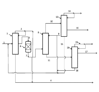
corrosion.
[0003] The reaction to produce MTBE is known to be reversible, i.e., the
MTBE will
dissociate to produce methanol and isobutene that were originally combined to
produce the MTBE. For example, U.S. Pat. Nos. 3,121,124; 3,170,000; 3,634,534;
3,634,535; 4,232,177 and 4,320,232 disclose the dissociation of alkyltertiary
alkyl
ethers using ion exchange resin catalysts.
[0004] The use of acid cation exchange resins in the past for the
dissociation of
methyl tertiary butyl ether has been demonstrated, i.e., U.S. Pat. No.
3,121,124
(Verdol) using a gel type catalyst (Dowex 50) and U.S. Pat. No. 4,232,177
(Smith)
used a macroreticular catalyst (Amberlyst 15) in a catalytic distillation
process. The
dissociation of MTBE will produce a stream containing isobutene, methanol, and
some oxygenated compounds and polymer impurities.
SUMMARY OF INVENTION
[0005] The product stream resulting from MTBE decomposition, as noted
above,
includes various impurities. Further, the products may form azeotropes. Each
of
1
CA 03112587 2021-03-11
WO 2020/055963 PCT/US2019/050553
these may make the desired separations into high purity product streams more
difficult.
[0006] Embodiments herein are directed toward systems and processes to co-
produce
a high purity methanol stream along with a targeted isobutene product.
[0007] In one aspect, embodiments herein are directed toward systems for
producing
isobutene and a high purity methanol product. The systems may include a system
for the production of isobutene, the process comprising a first fractionation
system
which receives a feed stream comprising crude MTBE, and which produces an
MTBE product stream comprising at least 94wt% MTBE and a heavies stream; a
first reactor configured for contacting the MTBE product stream with a
catalyst to
provide an effluent comprising isobutene and methanol; an extraction unit
configured for contacting the effluent comprising isobutene and methanol with
one
or more extractants to produce an extractant/methanol stream and a mixed
isobutene
stream; a second fractionation system which receives the mixed isobutene
stream,
and which produces a stream comprising isobutene comprising at least 95wt%
isobutene; and a third fractionation system which receives the
extractant/methanol
stream, and which produces a methanol stream comprising at least 95wt%
methanol,
a lights fraction, and a heavies fraction comprising extractant.
[0008] In one aspect, embodiments herein are directed toward processes
for
producing isobutene and a high purity methanol product. The processes may be a
process for the coproduction of isobutene and high purity methanol, the
process
comprising separating a feed stream comprising crude MTBE in a first
fractionation
system to recover an MTBE product stream comprising at least 94wt% MTBE, and
to recover a heavies stream; contacting the MTBE product stream with a
catalyst to
provide an effluent comprising isobutene and methanol; contacting the effluent
comprising isobutene and methanol with one or more extractants to produce an
extractant/methanol stream and a mixed isobutene stream; feeding the mixed
isobutene stream into a second fractionation system to recover a stream
comprising
isobutene comprising at least 95wt% isobutene; and feeding the
extractant/methanol
stream into a third fractionation system to recover a lights fraction, a
methanol
product stream comprising at least 95wt% methanol and a heavies fraction
comprising the extractant.
2
CA 03112587 2021-03-11
WO 2020/055963 PCT/US2019/050553
[0009] In another embodiment, the process may be a process for the
coproduction of
isobutene and high purity methanol, the process comprising separating a feed
stream
comprising crude MTBE in a first fractionation system to recover an MTBE
product
stream comprising at least 94wt% MTBE, and to recover a heavies stream;
contacting the MTBE product stream with a catalyst to provide an effluent
comprising isobutene and methanol; contacting the effluent with one or more
extractants to produce an extractant/methanol stream and a mixed isobutene
stream;
feeding the mixed isobutene stream into a second fractionation system to
recover a
stream comprising isobutene comprising at least 95wt% isobutene; and feeding
the
extractant/methanol stream into a third fractionation system comprising a
divided
wall distillation column to recover an overheads fraction, a methanol side
draw
product stream comprising at least 95wt% methanol and a bottoms stream
comprising the extractant.
[0010] In yet other embodiments, the process me be a process for the
coproduction of
isobutene and high purity methanol, the process comprising separating a feed
stream
comprising crude MTBE, C4s, C5s, diisobutene (DIB), tertiary butyl acohol
(TBA)
and 2-methoxybutane (MSBE) in a first fractionation system to recover an MTBE
product stream comprising at least 94wt% MTBE, and to recover a heavies stream
comprising a mixture of MTBE, tert-butyl alcohol (TBA), and 2-methoxybutane
(MSBE); contacting the MTBE product stream with a catalyst to provide an
effluent
comprising isobutene, methanol, and residual MTBE; contacting the effluent
with
one or more extractants to produce an extractant/methanol stream and a mixed
isobutene/MTBE stream; feeding the mixed isobutene/MTBE stream into a second
fractionation system to recover a stream comprising isobutene comprising at
least
94wt% isobutene and a heavies stream comprising MTBE/isobutene; recycling the
heavies stream comprising MTBE/isobutene to the first fractionation system;
feeding the extractant/methanol stream into a third fractionation system
comprising
a divided wall distillation column to recover an overheads fraction, a
methanol side
draw product stream comprising at least 95wt% methanol and a bottoms stream
comprising residual MTBE, methanol, and the extractant; and recycling the
bottoms
stream comprising residual MTBE, methanol, and the extractant to the first
fractionation system.
3
CA 03112587 2021-03-11
WO 2020/055963 PCT/US2019/050553
BRIEF DESCRIPTION OF DRAWINGS
[0011] Figure 1 is a simplified process flow diagram of a process for an
integrated
reactor system according to embodiments disclosed herein.
[0012] Figure 2 is a simplified process flow diagram of a process for an
integrated
reactor system according to embodiments disclosed herein.
[0013] Figure 3 is an illustration of a divided wall column according to
embodiments
disclosed herein.
[0014] Figure 4 is an illustration of a divided wall column according to
embodiments
disclosed herein.
DETAILED DESCRIPTION
[0015] In one aspect, methods and systems for producing high purity
methanol from
crude MTBE feed using one or mulitple divided wall columns are provided. The
method can include purifying the MTBE, dissociating the MTBE to produce
isobutene and methanol, purifying the isobutene and recovering/purifying
methanol.
[0016] Divided wall columns herein may be used to separate multicomponent
mixtures into pure fractions. They are particularly suited to obtain high
purity
medium boiling fractions. The separation of a three-component mixture into its
fractions in conventional distillation systems requires a sequential system
with at
least two columns or main columns with side columns. With a divided wall
column,
only one fractionator is used to separate lights and heavies from the medium
boiling
point product. A vertical wall is introduced in the middle part of the column,
creating a feed and draw-off section in this part of the column. This
arrangement
saves a second column. The column shell, internals, reboiler and condenser for
a
second column are not needed.
[0017] As used herein, the term "divided wall column" refers to any
column having a
dividing wall suitable for the separation of a mixture containing two or more
components having differing boiling points. As used herein, the term "dividing
wall" refers to any partition disposed at least partially within an interior
of a column
to provide at least a first fractionation zone on one side of the dividing
wall and a
4
CA 03112587 2021-03-11
WO 2020/055963 PCT/US2019/050553
second fractionation zone on the other side of the dividing wall. The dividing
wall
can be either segmented or continuous. The dividing wall can be parallel or
non-
parallel relative to a longitudinal axis of the column. The first
fractionation zone and
the second fractionation zone can have the same or different cross-sectional
areas
and/or volumes. The column can have a circular cross-section and the dividing
wall
can positioned or disposed within the column to provide the first
fractionation zone
and the second fractionation zone having equal or un-equal cross-sectional
areas
with respect to one another. The dividing wall can extend completely or only
partially from one side of the dividing wall column to the other side of the
dividing
wall column.
[0018] A divided wall column according to embodiments herein is, in
principle, a
system of thermally coupled distillation columns. In divided wall columns
herein, a
dividing wall is located in the interior space of the column. Divided wall
columns
herein may use a chord wall or an annular wall. The dividing wall generally is
vertical. Two different mass transfer separations occur on either side of the
dividing
wall, which may have different operating pressures and temperatures, the
dividing
wall may have to withstand a pressure differential and/or a temperature
differential
across the dividing wall.
[0019] Divided wall columns herein may include internals which comprise
trays,
rotating trays, random and/or structured packings. Useful column trays include
the
following types: trays having drillholes or slots in the tray plate; trays
having throats
or chimneys which are covered by bubble-caps, caps or hoods; trays having
drillholes in the tray plate which are covered by movable valves; trays having
special constructions. In columns having rotating internals, the reflux is
either
sprayed by rotating funnels or distributed as a film onto a heated tube wall
with the
aid of a rotor. Columns may comprise random packings of various shaped bodies.
[0020] The divided wall columns may have common stripping and
rectification
sections with the divided wall being located in the middle. Such a design
allows for
effecting different vapor and liquid travel on either side of the wall, thus
increasing
product purity while minimizing equipment unit count.
CA 03112587 2021-03-11
WO 2020/055963 PCT/US2019/050553
[0021] A methanol feed, for example, may be processed according to
embodiments
herein to produce the highest methanol concentration within the divided wall
column
while minimizing the amount of methanol leaving with the bottoms product. This
results in close to the azeotropic concentration in the distillate product and
in the
distillation zone. The methanol must be separated from the hydrocarbons so
that the
hydrocarbons may be used for gasoline blending and to conserve methanol. The
separation may be achieved by washing the hydrocarbon/methanol mixture with
water. The methanol may be selectively absorbed in the water phase, which is
subsequently fractionated to separate the methanol.
[0022] The divided wall column, according to one or more embodiments
disclosed
herein, may be used in an existing integrated MTBE and isobutene facility, for
example, and may produce high purity isobutene only. The existing facility may
have
all the methanol produced from the isobutene unit being recycled to the MTBE
unit.
In order to process additional import MTBE and to make export quality
commercial
grade methanol at the same time, a new methanol purification section would
need to
be installed in such a facility. Such a methanol purification section may need
to have
two distillation columns (methanol topping and methanol tailing columns) with
associated equipment. The divided wall column disclosed herein may be used
instead
of multiple separate traditional, columns for the production of commercial
grade
methanol.
[0023] Additionally, the integrated MTBE and isobutene process may not
have the
flexibility to produce commercial grade methanol. In order to co-produce
methanol by
including additional MTBE import in the isobutene section, a methanol
purification
section may need to be integrated in the process. This methanol purification
process
may involve a dividing wall column, or a series of distillation columns, to
achieve an
on-specification methanol product while using minimal pieces of equipment.
Additionally, the reboiling/condensing duty of the process may be around 30%
lower
than a two column conventional system. Finally, as the divided wall column may
use
less equipment, there is a significant saving in required plot area and
structure (pipe
rack, foundation, etc.).
6
CA 03112587 2021-03-11
WO 2020/055963 PCT/US2019/050553
[0024] According to one or more embodiments disclosed herein is a divided
wall
column, or series of distillation columns, which may take the bottoms of an
extraction
column and separate out one or more of MTBE, DIB, TBA, DME, MSBE, TAME,
and water from the methanol to make an export grade methanol product.
[0025] The method to produce high purity isobutene will now be described
with
reference to Fig. 1. To purify the MTBE, crude MTBE 1 is introduced into a
fractionation column 5. Crude MTBE 1 may be obtained from isobutenic C4 olefin
mixtures, for example from the C4 cut from steam crackers or FCC units. The
crude
MTBE may also include methanol, secondary butyl alcohol (SBA), tert-butyl
alcohol (TBA), 2-methoxybutane (MSBE), diisobutene, tertiary amyl methyl ether
(TAME) and other high boiling point components.
[0026] In some embodiments, the crude MTBE stream 1 may include a 94-97
wt%
MTBE stream, such as a 95.9 wt. % MTBE. The crude MTBE stream 1 may also
contain small amounts of highly unsaturated compounds such as 1,3-butadiene,
trans-1,3-pentadiene, cis-1,3-pentadiene, 2-methyl-1,3-butadiene, and others.
The
feed stream may additionally comprise crude MTBE provided from an upstream
etherification reaction zone and a supplemental MTBE feed stream. Such
supplemental MTBE feed stream may come from a separate facility, OSBL, an
upstream separation system, or other sources.
[0027] The MTBE stream 1 can be introduced at an intermediate point in
the column
5. A light hydrocarbon stream 2 can be withdrawn from the column 5 at or
proximal
the first end thereof and a side-stream 3 can be withdrawn from an
intermediate
point in the column 5. The light hydrocarbon stream 2 may be recycled to the
top of
the column 5 as a reflux. The light hydrocarbon stream 2 may be a mixture of
MTBE, methanol, water, and highly unsaturated compounds. The side-stream may
be an MTBE stream of increased purity as compared to the MTBE feed stream 1.
The side stream may further include one or more impurities present in the feed
stream. A heavy hydrocarbon stream 4 can be withdrawn from the divided wall
column 5 at or proximal the lower end thereof. The heavy hydrocarbon 4 may be
a
mixture of MTBE, tert-butyl alcohol (TBA), 2-methoxybutane (MSBE) and higher
olefins.
7
CA 03112587 2021-03-11
WO 2020/055963 PCT/US2019/050553
[0028] The fractionation column 5 may operate at temperatures ranging
from about
45 C to about 130 C and pressures ranging from about 0.1 to about 5 barg. The
purification of MTBE 1 provides the sidestream (MTBE) 3 having a composition
such as about 99.5 wt % MTBE or greater, such as 99.8 wt% MTBE or 99.9 wt%
MTBE. The MTBE side stream may be produced by fractional distillation in the
fraction system 5, separating the MTBE 1 into the light hydrocarbons 2
comprising
MTBE, methanol, water and other low boiling components, and the heavy
hydrocarbons 4 comprising butene oligomers, TBA, and other high boiling
components, while withdrawing the high purity MTBE sidestream 3.
[0029] To produce isobutene, the MTBE sidestream 3 may be sent to a
reactor 6 to
produce isobutene. The reactor 6 dissociates the high purity MTBE 3 and
produces
a raw isobutene stream 7 comprising isobutene, methanol and unreacted MTBE. In
some embodiments, the reactor 6 includes a fixed bed operating at reaction bed
temperatures ranging from about 90 C to about 160 C, in other embodiments from
about 120 C to about 150 C. The high purity MTBE 3 may be fed at an inlet
temperature of about 110 C to about 150 C in some embodiments, about 115 C to
about 145 C in other embodiments. The reactor 6 may have an LHSV (liquid
hourly space velocity) ranging from about 7 to about 35, or from about 10 to
about
30, or from about 14 to about 25. The reactor 6 may have a pressure drop
through
said fixed bed in the range of about 0.5 to about 50 psig and at a reaction
pressure
ranging from about 0.5 to about 4 atmospheres.
[0030] The raw isobutene stream 7 is sent for product purification. The
raw isobutene
7 may be sent to an extraction column 8 to extract methanol and unreacted MTBE
from isobutene. The extraction column 8 uses an extractant 9 fed in a
countercurrent
fashion to the raw isobutene 7 thereby producing a washed reactor effluent 10
as an
overhead and a bottoms product 11. The washed reactor effluent 10, which may
include isobutene. MTBE, and residual light components, may be fed to an
isobutene fractionation system 12 and the bottoms product 11, which may
include
water, methanol, MTBE, and residual heavy components, may be fed to a methanol
fractionation system 13. The extractant 9 may be water or another suitable
extractant
useful to separate methanol from isobutene.
8
CA 03112587 2021-03-11
WO 2020/055963 PCT/US2019/050553
[0031] In various embodiments, at least a portion of the raw isobutene 7
may be
recycled to the first fraction system 5 as additional reflux, collected as
product,
and/or combined with the heavy hydrocarbons 4 and sent offsite as byproduct.
[0032] To recover the isobutene, the method may include introducing the
washed
reactor effluent 10 to an isobutene fractionation system 12, similar to that
as
described above for the purification of the MTBE. The washed reactor effluent
10
may be introduced at an intermediate point of the isobutene fractionation
column 12.
A light ends overhead 14 can be withdrawn from the isobutene fractionation
column
12 at or proximal the upper end thereof and may be vented or recycled to the
isobutene fractionation system 12 as reflux. A side-stream of high purity
isobutene
16 can be withdrawn from an intermediate point of the isobutene fractionation
column 12, which may be used in downstream processes, or may be recovered as a
product and sent offsite. Such high purity isobutene stream may have a purity
of
95wt%, 97wt%, 98wt%, 99wt%, 99.5wt%, 99.6wt%, 99.7wt%, 99.8wt%, or even
99.85wt% isobutene. The isobutene column 12 may also produce a bottom product
15, which may be a mixture of isobutene, MTBE and/or water which may be
recycled to fractionation system 5. The isobutene column 12 may operate at
temperatures ranging from about 45 C to about 150 C and pressures ranging from
about 3 to about 15 barg.
[0033] To recover/purify a methanol product stream, the bottoms product
11 from the
extraction column 8 may be fed to an inteiniediate point of the methanol
fractionation system 13. The methanol fractionation system may a series of
fractionation columns such a methanol toppings column followed by a methanol
bottoms bottom column, or may be a divided wall column as will be described
below. The methanol fraction system 13 may provide a high purity methanol
product 17 withdrawn as a sidestream from an intermediate point of the
methanol
column 13, a bottoms stream 18, and an overhead stream 19. The light overhead
stream 19 may comprise methanol and other light components and may be vented
or
recycled to the methanol fractionation system 13 as reflux. The bottoms 18 may
include water, TBA, MTBE and/or methanol. The bottoms 18 may be recycled to
either the extraction column 8 or the fractionation system 5. The methanol
column
9
CA 03112587 2021-03-11
WO 2020/055963 PCT/US2019/050553
13 may operate at temperatures ranging from about 45 C to about 180 C and
pressures ranging from about 01 to about 5 barg.
[0034] In about embodiments disclosed herein, as illustrated in Fig. 2,
the first
fraction system 5 may recover MTBE in the overhead products. The overall
process
scheme will proceed similarly, with residual MTBE, water, and isobutene being
recycled in bottoms stream 15. Additionally, methanol, residual isobutene, and
other light components may be recycled to the first fraction system via
flowline 19.
[0035] The overall processing schemes disclosed herein may be performed
using
single fraction columns, a series of fraction columns, or divided wall
columns.
Resulting advantages of using divided wall columns may include: reduced
capital
investment; and elimination or significant reduction in the need for multiple
columns
to provide the same level of purity of products, among other advantages.
[0036] In one aspect, embodiments herein relate to the use of a dividing
wall
distillation column. The feed to the dividing wall column may be from a prior
column
or reactor in which less than all of the reactants were reacted. The feed
material
contains the reactants and product which is fed to a pre-fraction section of
the
dividing wall column. A post-fraction section then produces the methanol
product as a
side draw. Between the pre- and post-fractionation sections is a common
bottoms
section that recovers as much methanol as possible while concentrating the
water and
TBA into the bottoms product. The overhead of the column serves to reflux the
pre-
fractionation section, acts as the feed/reflux to the post-fractionation
section, and a
portion is drawn as the overheads product that may be sent back to an MTBE
synthesis section. Makeup material may be added as required. There may be a
common stripping section below the divided vertical section.
[0037] The pre-fractionation section is responsible for separating
methanol/ MTBE
from water and TBA. This section may be refluxed such that a separation is
made
between the methanol and the water/TBA. The post-fractionation section of the
dividing wall column may separate the MTBE from a portion of the methanol.
And, a
side draw may draw the methanol product from the post-fractionation section.
Sufficient reflux may be sent to this section to maximize the recovery of
methanol,
while minimizing the amount of impurities, in the side draw product. The
section of
CA 03112587 2021-03-11
WO 2020/055963 PCT/US2019/050553
the column below the dividing wall may include sufficient mass transfer
packing or
catalyst to further recover methanol from water/TBA exiting the bottom of the
pre-
fractionation section. The liquid coming from the pre- and post-fractionation
sections
and collecting in the common bottoms section serves as the internal reflux for
this
portion of the column.
[0038] Further, the ancillary equipment for this tower may be similar to
that as used
on any distillation column. For example, the system may include a common
overhead
system, recovering the overhead from each of the pre- and post-fractionation
sections
of the dividing wall column. The condenser may be a total condenser which
condenses the vapor coming from the pre- and post-fractionation sections. The
condensed overhead may then be directed to a reflux accumulator, or overhead
drum,
the effluent of which may be split between the overhead product and the reflux
for the
tower. The reflux may be fed to the pre-fractionation, the post-fractionation,
or both,
in equal or unequal amounts, depending on the column separation dynamics. The
column may use a single, common reboiler to provide the required boil-up for
the
separation.
[0039] Additionally, the product stream drawn from the side draw may be
fed to a
product cooler which brings the methanol to transport temperatures.
[0040] According to one or more embodiments disclosed herein, the
distillation
column may have at least two vertical distillation sections, including a pre-
fraction
section with the inlet feed, and a post-fractionation section with a side
draw. The
dividing wall column may also have at least one wall separating the at least
two
vertical distillation sections. The wall may extend through a vertical portion
of the
distillation column, the wall extending less than the total height of the
column. The
dividing wall column may also be equipped with a common stripping section
below
the at least two vertical distillation sections. The common stripping section
may be in
fluid communication around the bottom vertical terminus of the wall. The wall
extending through the vertical portion of the distillation column may extend
from the
top of the column to about the top of the stripping section.
11
[0041] Additionally, the dividing wall colunur may have a common overhead
condenser system. The common overhead condenser system may receive an overhead
product from the at least two vertical distillation sections, and may feed the
overheads
to a common overheads drum. The common overheads drum may be equipped with
all the necessary piping and valving to recycle a condensed overhead product
each of
the at least two vertical distillation sections.
[0042] The pre- and post-fraction sections may be located completely, or
partially, in
the rectification section of the distillation column. The dividing wall column
may use
a side draw located in the rectification section of the post-fraction section
and may be
configured for product recovery. Additionally, the dividing wall column may
use a
common bottoms reboiler, which may provide the entire heating duty for boil-up
and
a separate bottoms product stream. The overheads drum may also have an
overhead
products stream.
[0043] Referring now to Fig. 3, a methanol purification process which uses
the
fractionation system 13 shown in FIGs. 1 and 2 may be carried out in the
dividing
wall column and may operate generally as follows.
[0044] Feedstock 102, which may include one or more of MTBE, DIB, IBA, DME,
MSBE, TAME, water, and methanol, is fed to pre-fractionation section A. As
illustrated, pre-fractionation section A may separate one or more feed
components to
produce methanol. Liquid travels down the dividing wall column and into the
common stripping section C. Vapor exits the top of the section A by overheads
stream
104A and enters the common overheads condenser 106.
[0045] A first portion of the liquids in the commons stripping section C is
fed to the
common reboiler 110 through a first bottoms outlet 108. A second portion of
the
liquids in the common stripping section C is recovered by outlet 112. Both
portions
may include water, TBA, other heavy components, and some residual methanol.
The
vapor portion traveling upwards out of commons stripping section C may flow
into
the pre-fractionation section A and the post-fractionation section B.
[0046] In all cases, the vapor traveling upwards in the column may be
purposely
divided at the lowermost terminus of the dividing wall in a prescribed ratio
as
determined beforehand from rigorous reactive-distillation simulation of the
divided-
12
Date Recue/Date Received 2022-09-16
CA 03112587 2021-03-11
WO 2020/055963 PCT/US2019/050553
wall configuration. Such division of flow may be controlled to prescribed
values by
engineering-design methods incorporating either active or passive means.
Again, such
division of flow may held at prescribed values using engineering design
methods
incorporating either active or passive means. Such means include having a
larger
bottom opening on section A or section B, the dividing wall being off-center,
or the
amount of reflux being fed to section A or section B.
[0047] The post-fractionation section B may include the product side draw
114. The
side draw product may be substantially pure methanol. As defined herein,
substantially pure may be a purity of at least 95wt%, 97wt%, 98wt%, 99wt%,
99.5wt%, 99.6wt%, 99.7wt%, 99.8wt%, or even 99.85wt%. The product methanol
may be fed through a product cooler 115 to be prepared for transport.
[0048] As with the pre-fractionation section, the post-fractionation
section B may
separate one or more feed components to produce methanol. Liquid travels down
the
dividing wall column and into the common stripping section C. Vapor exits the
top of
the section B by overheads stream 104B and enters the common overheads
condenser
106. Overhead streams 104A and 104B are combined into a common overheads
stream 104.
[0049] The combined, condensed overheads 116 may be fed to an overheads
collection drum 118. A vapor portion 124 exiting the overheads drum may be
used to
un-deadhead the column and increase vapor travel through sections A, B, and C.
The
vapor portion 124 may be recycled to upstream processes, or downstream
processes,
or flared, as necessary.
[0050] A liquid portion 120 exiting the overheads collection drum 118 may
be fed, as
reflux, to post-fractionation section B via stream 121, pre-fractionation
section A via
stream 122, or both. A portion of the liquid portion 120 which is not fed as
reflux may
be recovered via stream 123 and recycled to upstream processes, downstream
process,
or flared, as necessary.
[0051] The division of the reflux as to how much goes to zone A versus
how much
goes to zone B may be intentionally designed for and may be controlled.
Appropriate
valving may be used to vary the amount of reflux fed to zone A or zone B at
any
13
CA 03112587 2021-03-11
WO 2020/055963 PCT/US2019/050553
given time. For example, the dividing wall column may be operated such that no
vapor portion 124 is removed, and the totality of the reflux may be fed to
either zone
A or zone B. Alternatively, the dividing wall column may be operated such that
no
vapor portion 124 is removed, and the totality of the reflux may be fed to
zone A and
zone B in equal, or unequal, amounts. Alternatively, the dividing wall column
may be
operated such that vapor portion 124 is removed, and the totality of the
liquid reflux
may be fed to either zone A or zone B. Or alternatively, the dividing wall
column may
be operated such that vapor portion 124 is removed, and the totality of the
liquid
reflux may be fed to zone A and zone B in equal, or unequal, amounts.
[0052] In one or more embodiments herein, the light components may be
concentrated and purged as overhead product. Purging of lights is needed to
control
temperatures in catalytic distillation columns.
[0053] Section A parallels section B and is fed via liquid reflux from
the overhead
condenser system and vapor from stripping section C and the reboiler. The
split of the
vapor between section A and section B may be intentionally controlled at
prescribed
levels using either active or passive engineering-design means.
[0054] In another embodiment disclosed herein, the distillation column
may have at
least two vertical distillation sections, including a pre-fraction section
with the inlet
feed, and a post-fractionation section with a side draw. The dividing wall
column may
also have at least one wall separating the at least two vertical distillation
sections. The
wall may extend through a mid portion of the distillation column, the wall
extending
less than the total height of the column. The dividing wall column may also be
equipped with a common stripping section below the at least two vertical
distillation
sections. The common stripping section may be in fluid communication around
the
bottom vertical terminus of the wall.
[0055] Additionally, the dividing wall column may have a common overhead
condenser system. The common overhead condenser system may receive an overhead
product from the at least two vertical distillation sections, and may feed the
overheads
to a common overheads drum. The common overheads drum may be equipped with
14
all the necessary piping and valving to recycle a condensed overhead product
to the
top tray of each of the at least two vertical distillation sections.
[0056] The pre- and post-fraction sections may be located completely, or
partially, in
the rectification section of the distillation column. The dividing wall column
may use
a side draw located in the rectification section of the post-fraction section
and may be
configured for product recovery. Additionally, the dividing wall column may
use a
common bottoms reboiler, which may provide the entire heating duty for boil-up
and
a separate bottoms product stream. The overheads drum may also have an
overhead
products stream.
[0057] Referring now to Fig. 4, a methanol purification process which uses
the
fractionation system 13 shown in FIGs. 1 and 2 may be carried out in the
dividing
wall column and may operate generally as follows.
[0058] Feedstock 202, which may include one or more of MTBE, DIB, 'IBA,
DME,
MSBE, TAME, water, and methanol, is fed to pre-fractionation section A. As
illustrated, pre-fractionation section A may separate one or more feed
components to
produce methanol. Liquid travels down the dividing wall column and into the
common stripping section C. Vapor exits the top of the section A by overheads
stream
204 and enters the common overheads condenser 206.
[0059] A first portion of the liquids in the commons stripping section C is
fed to the
common reboiler 210 through a first bottoms outlet 208. A second portion of
the
liquids in the common stripping section C is recovered by outlet 212. Both
portions
may be water, TBA, other heavy components, and some residual methanol. The
vapor
portion travel upwards out of commons stripping section C may flow into the
pre-
fractionation section A and the post-fractionation section B.
[0060] In all cases, the vapor traveling upwards in the column may be
purposely
divided at the lowermost terminus of the dividing wall in a prescribed ratio
as
determined beforehand from rigorous reactive-distillation simulation of
divided-wall
configuration. Such division of flow may be controlled to prescribed values by
engineering-design methods incorporating either active or passive means.
Again, such
division of flow may held at prescribed values using engineering design
methods
incorporating either active or passive means. Such means include having a
larger
Date Recue/Date Received 2022-09-16
CA 03112587 2021-03-11
WO 2020/055963 PCT/US2019/050553
bottom opening on section A or section B, the dividing wall being off-center,
or the
amount of reflux being fed to section A or section B.
[0061] The post-fractionation section B may include the product side draw
214. The
side draw product may be substantially pure methanol. As defined herein,
substantially pure may be a purity of at least 95wt%, 97wt%, 98wt%, 99wt%,
99.5wt%, 99.6wt%, 99.7wt%, 99.8wt%, or even 99.85wt%. The product methanol
may be fed through a product cooler 215 to be prepared for transport.
[0062] As with the pre-fractionation section, the post-fractionation
section B may
separate one or more feed components to produce methanol. Liquid travels down
the
dividing wall column and into the common stripping section C. Vapor exits the
top of
the section B by overheads stream 204 and enters the common overheads
condenser
206.
[0063] The combined, condensed overheads 216 may be fed to an overheads
collection drum 218. A vapor portion 224 exiting the overheads drum may be
used to
un-deadhead the column and increase vapor travel through sections A, B, and C.
The
vapor portion 224 may be recycled to upstream processes, or downstream
processes,
or flared, as necessary.
[0064] A liquid portion 220 exiting the overheads collection drum 218 may
be fed, as
reflux, to an area approximate the top tray in post-fractionation section B
via stream
221, to area approximate the top tray in pre-fractionation section A via
stream 222, or
both. A portion of the liquid portion 220 which is not fed as reflux may be
recovered
via stream 223 and recycled to upstream processes, downstream process, or
flared, as
necessary.
[0065] The division of the reflux as to how much goes to zone A versus
how much
goes to zone B may be intentionally designed for and may be controlled.
Appropriate
valving may be used to vary the amount of reflux fed to zone A or zone B at
any
given time. For example, the dividing wall column may be operated such that no
vapor portion 224 is removed, and the totality of the reflux may be fed to
either zone
A or zone B. Alternatively, the dividing wall column may be operated such that
no
vapor portion 224 is removed, and the totality of the reflux may be fed to
zone A and
16
CA 03112587 2021-03-11
WO 2020/055963 PCT/US2019/050553
zone B in equal, or unequal, amounts. Alternatively, the dividing wall column
may be
operated such that vapor portion 224 is removed, and the totality of the
liquid reflux
may be fed to either zone A or zone B. Or alternatively, the dividing wall
column may
be operated such that vapor portion 224 is removed, and the totality of the
liquid
reflux may be fed to zone A and zone B in equal, or unequal, amounts.
[0066] In one or more embodiments herein, the light components may be
concentrated and purged as overhead product. Purging of lights is needed to
control
temperatures in catalytic distillation columns.
[0067] Section A parallels section B and is fed via liquid reflux from
the overhead
condenser system and vapor from stripping section C and the reboiler. The
split of the
vapor between section A and section B may be intentionally controlled at
prescribed
levels using either active or passive engineering-design means. Control of
reflux to
section A and section B may be above the top tray for each section or may be
controlled by internals within the column.
[0068] In a conventional distillation column reactor there is generally a
reflux of
condensed overheads to facilitate the separation of the more volatile
unreacted
components from the product. In the case of purification of methanol, the
overheads
may contain methanol, and other lighter materials which might be in the feed.
The
condensable overheads are recovered and the methanol may be separated from the
hydrocarbons by water washing, the methanol being selectively removed in the
water
phase. The methanol and water may then be refluxed and the methanol further
separator in the distillation column.
[0069] Further, in other embodiments, the methanol distillation column
may be a
series of distillation columns operated in parallel such that a high purity
methanol
stream may be obtained.
[0070] While the disclosure includes a limited number of embodiments,
those skilled
in the art, having benefit of this disclosure, will appreciate that other
embodiments
may be devised which do not depart from the scope of the present disclosure.
Accordingly, the scope should be limited only by the attached claims.
17