Note: Descriptions are shown in the official language in which they were submitted.
CLEANING HEAD FOR A SURFACE TREATMENT APPARATUS HAVING ONE OR
MORE STABILIZERS AND SURFACE TREATMENT APPARATUS HAVING THE
SAME
CROSS-REFERENCE TO RELATED APPLICATIONS
[0001] The present application claims the benefit of U.S. Provisional
Application Serial No.
62/733,239 filed on September 19, 2018, entitled Cleaning Head for a Surface
Treatment
Apparatus having one or more Stabilizers and Surface Treatment Apparatus
having the same
and of U.S. Provisional Application Serial No. 62/862,436 filed on June 17,
2019, entitled
Cleaning Head for a Surface Treatment Apparatus having one or more Stabilizers
and Surface
Treatment Apparatus having the same.
IECHNICAL FIELD
[0002] The present disclosure is generally directed to surface treatment
apparatuses and more
specifically to a cleaning head for a surface treatment apparatus having one
or more stabilizers.
BACKGROUND INFORMATION
[0003] Surface treatment apparatuses may include vacuum cleaners configured to
suction
debris from a surface (e.g., a floor). The vacuum cleaner may include a
surface cleaning head
having one or more brush rolls configured to agitate a surface (e.g., a
carpet) to urge debris into
an airflow generated by the vacuum cleaner. The debris within the airflow may
then be
deposited in a debris collector for later disposal.
BRIEF DESCRIPTION OF THE DRAWINGS
[0004] These and other features and advantages will be better understood by
reading the
following detailed description, taken together with the drawings, wherein:
[0005] FIG. 1 shows a schematic view of a vacuum cleaner in a storage
position, consistent
with embodiments of the present disclosure.
[0006] FIG. 2 shows a schematic view of the vacuum cleaner of FIG. 1 in an in-
use position,
consistent with embodiments of the present disclosure.
[0007] FIG. 3 shows a perspective view of a surface cleaning head coupled to a
wand, wherein
the wand is in a storage position, consistent with embodiments of the present
disclosure.
1
Date Regue/Date Received 2022-10-26
CA 03113028 2021-03-16
WO 2020/061285
PCT/US2019/051889
[0008] FIG. 4 shows a perspective view of the surface cleaning head of FIG. 3
having the wand
in an in-use position, consistent with embodiments of the present disclosure.
[0009] FIG. 5 shows a perspective cutaway view of an example of the surface
cleaning head
of FIG. 3, consistent with embodiments of the present disclosure.
[0010] FIG. 6 shows a cross-sectional view of the surface cleaning head of
FIG. 5, consistent
with embodiments of the present disclosure.
[0011] FIG. 7 shows a perspective view of another example of the surface
cleaning head of
FIG. 3, consistent with embodiments of the present disclosure.
[0012] FIG. 8 shows a perspective view of the surface cleaning head of FIG. 7,
consistent with
embodiments of the present disclosure.
[0013] FIG. 9 shows a side view of the surface cleaning head of FIG. 7,
consistent with
embodiments of the present disclosure.
[0014] FIG. 10 shows a side view of a surface cleaning head having a neck in a
storage
position, consistent with embodiments of the present disclosure.
[0015] FIG. 11 shows a side view of the surface cleaning head of FIG. 10
having the neck in
an in-use position, consistent with embodiments of the present disclosure.
[0016] FIG. 12 shows a perspective view of the surface cleaning head of FIG.
10 having the
neck in the storage position, consistent with embodiments of the present
disclosure.
[0017] FIG. 13 shows a perspective view of the neck of FIG. 10, consistent
with embodiments
of the present disclosure.
[0018] FIG. 14 shows another perspective view of the neck of FIG. 10,
consistent with
embodiments of the present disclosure.
[0019] FIG. 15 shows a side view of the surface cleaning head of FIG. 10,
wherein the neck is
in an in-use position, consistent with embodiments of the present disclosure.
[0020] FIG. 16 shows a perspective view of a surface cleaning head, consistent
with
embodiments of the present disclosure.
[0021] FIG. 17 shows another perspective view of the surface cleaning head of
FIG. 16,
consistent with embodiments of the present disclosure.
[0022] FIG. 18 shows a side view of a surface cleaning head in a storage
position, consistent
with embodiments of the present disclosure.
[0023] FIG. 19 shows a side view of the surface cleaning head of FIG. 18 in an
in-use position,
consistent with embodiments of the present disclosure.
[0024] FIG. 20 shows a perspective view of the surface cleaning head of FIG.
18, consistent
with embodiments of the present disclosure.
2
CA 03113028 2021-03-16
WO 2020/061285
PCT/US2019/051889
[0025] FIG. 21 shows another perspective view of the surface cleaning head of
FIG. 18,
consistent with embodiments of the present disclosure.
[0026] FIG. 22 shows a perspective view of a surface cleaning head in a
storage position,
consistent with embodiments of the present disclosure.
[0027] FIG. 23 shows a perspective view of the surface cleaning head of FIG.
22 in an in-use
position, consistent with embodiments of the present disclosure.
[0028] FIG. 24 shows a perspective view of the surface cleaning head of FIG.
22 coupled to a
suction device, consistent with embodiments of the present disclosure.
[0029] FIG. 25 shows a schematic view of a surface cleaning head, consistent
with
embodiments of the present disclosure.
[0030] FIG. 26 shows a perspective view of a surface cleaning head having a
plurality of
stabilizers in an extended position, consistent with embodiments of the
present disclosure.
[0031] FIG. 27 shows a perspective view of the surface cleaning head of FIG.
26 having the
plurality of stabilizers in the retracted position, consistent with
embodiments of the present
disclosure.
[0032] FIG. 28 shows a top view of the surface cleaning head of FIG. 26,
consistent with
embodiments of the present disclosure.
[0033] FIG. 29 shows a top view of the surface cleaning head of FIG. 27,
consistent with
embodiments of the present disclosure.
[0034] FIG. 30 shows an exploded perspective view of a portion of the surface
cleaning head
of FIG. 26, consistent with embodiments of the present disclosure.
[0035] FIG. 31 shows a perspective view of a linkage of the surface cleaning
head of FIG. 26,
consistent with embodiments of the present disclosure.
[0036] FIG. 32 shows a perspective view of the linkage of FIG. 31 in a first
pivot position
engaging the stabilizer of FIG. 26, consistent with embodiments of the present
disclosure.
[0037] FIG. 33 shows a perspective view of the linkage of FIG. 31 in a second
pivot position
engaging the stabilizer of FIG. 26, consistent with embodiments of the present
disclosure.
[0038] FIG. 34 shows a perspective view of the stabilizer of FIG. 26,
consistent with
embodiments of the present disclosure.
[0039] FIG. 35 shows a schematic side view of a surface cleaning head having a
stabilizer in
an extended position, consistent with embodiments of the present disclosure.
[0040] FIG. 36 shows a schematic side view of the surface cleaning head of
FIG. 35 having
the stabilizer in a retracted position, consistent with embodiments of the
present disclosure.
3
CA 03113028 2021-03-16
WO 2020/061285
PCT/US2019/051889
[0041] FIG. 37 shows a perspective view of a surface cleaning head having a
stabilizer in an
extended position, consistent with embodiments of the present disclosure.
[0042] FIG. 38 shows a perspective view of the surface cleaning head of FIG.
37 having the
stabilizer in a retracted position, consistent with embodiments of the present
disclosure.
[0043] FIG. 39 shows a perspective view of a surface cleaning head having a
stabilizer in an
extended position, consistent with embodiments of the present disclosure.
[0044] FIG. 40 shows a perspective view of the surface cleaning head of FIG.
39 having the
stabilizer in a retracted position, consistent with embodiments of the present
disclosure.
[0045] FIG. 41 shows a perspective view of a portion of a main body of the
surface cleaning
head of FIG. 37, consistent with embodiments of the present disclosure.
[0046] FIG. 42 shows another perspective view of a portion of the main body of
FIG. 41,
consistent with embodiments of the present disclosure.
[0047] FIG. 43 shows a cross-sectional view of a surface cleaning head,
consistent with
embodiments of the present disclosure.
[0048] FIG. 44 shows a schematic side view of a surface cleaning head having a
stabilizer in
an extended position, consistent with embodiments of the present disclosure.
[0049] FIG. 45 shows a schematic side view of the surface cleaning head of
FIG. 44 having
the stabilizer in a retracted position, consistent with embodiments of the
present disclosure.
[0050] FIG. 46 shows a schematic side view of a surface cleaning head having a
stabilizer in
an extended position, consistent with embodiments of the present disclosure.
[0051] FIG. 47 shows a schematic side view of the surface cleaning head of
FIG. 46 having
the stabilizer in a retracted position, consistent with embodiments of the
present disclosure.
[0052] FIG. 48 shows a side view of a surface cleaning head having a
stabilizer in an extended
position, consistent with embodiments of the present disclosure.
[0053] FIG. 49 shows a schematic perspective view of a stabilizer in a
retracted position,
consistent with embodiments of the present disclosure.
[0054] FIG. 50 shows a schematic perspective view of the stabilizer of FIG. 49
in an extended
position, consistent with embodiments of the present disclosure.
[0055] FIG. 51 shows a schematic side view of a surface cleaning head having a
stabilizer,
consistent with embodiments of the present disclosure.
[0056] FIG. 52 shows a schematic perspective view of a vacuum cleaner having a
stabilizing
system in a first position, consistent with embodiments of the present
disclosure.
4
CA 03113028 2021-03-16
WO 2020/061285
PCT/US2019/051889
[0057] FIG. 53 shows a schematic perspective view of the vacuum cleaner of
FIG. 52 having
the stabilizing system in a second position, consistent with embodiments of
the present
disclosure.
DETAILED DESCRIPTION
[0058] The present disclosure is generally directed to a surface treatment
apparatus having an
upright portion and a surface cleaning head pivotally coupled to the upright
portion. The
upright portion is transitionable between an in-use position and a storage
position by pivoting
the upright portion relative to the surface cleaning head. The surface
cleaning head includes at
least one stabilizer configured to transition from an extended position to a
retracted position in
response to, for example, transitioning the upright portion between the
storage position and the
in-use position. The stabilizer may improve the stability of the surface
treatment apparatus
when, for example, the surface treatment apparatus is not in-use without
substantially
interfering with the usage of the surface treatment apparatus. This may
prevent the surface
treatment apparatus from inadvertently tipping over and causing damage to, for
example, itself,
other objects, an animal, and/or a person.
[0059] FIG. 1 shows a schematic view of a vacuum cleaner 100 including a
surface cleaning
head 102 having one or more wheels 103 rotatably coupled thereto, an upright
section 104, a
dust cup 106, and a suction motor 108. The suction motor 108 is configured
generate an airflow
into an inlet 110 of the surface cleaning head 102 such that debris can be
suctioned from a
surface to be cleaned (e.g., a floor). At least a portion of debris that is
entrained within the
airflow is deposited in the dust cup 106 for later disposal by a user of the
vacuum cleaner 100.
After passing through the dust cup 106, the airflow is exhausted from the
suction motor 108 at
an exhaust outlet 112. The suction motor 108 can be powered by, for example,
one or more
batteries and/or an electrical grid.
[0060] As shown in FIG. 1, the upright section 104 is in a storage (or
upright) position. The
upright section 104 is pivotally coupled to a main body 101 of the surface
cleaning head 102
such that the upright section 104 can be pivoted to an in-use (or reclined)
position (e.g., as
shown FIG. 2). An axis about which the upright section 104 pivots when
transitioning between
the storage and in-use positions can extend substantially parallel to an axis
about which the one
or more wheels 103 rotate.
[0061] One or more stabilizers 114 can be provided that are configured to
transition between
an extended (e.g., as shown in FIG. 1) and retracted (e.g., as shown in FIG.
2) position in
response to, for example, the upright section 104 transitioning between the
storage and in-use
positions and/or in response to a user interaction. The stabilizer 114 can be
configured to
CA 03113028 2021-03-16
WO 2020/061285
PCT/US2019/051889
extend from the vacuum cleaner 100 and engage (e.g., contact) a surface (e.g.,
a floor) when
the upright section 104 is in the storage position. Such a configuration may
improve the
stability of the vacuum cleaner 100 when compared to a vacuum cleaner 100 that
does not
include the stabilizer 114.
[0062] As the upright section 104 is pivoted towards the in-use position, the
stabilizer 114 can
move towards the retracted position for at least a portion of the pivotal
movement such that the
stabilizer 114 does not substantially interfere with the use of the vacuum
cleaner 100. As such,
the surface cleaning head 102 can be moved across a surface to be cleaned
(e.g., a floor) without
the stabilizer 114 engaging (e.g., contacting) the surface to be cleaned. In
other words, the
stability of the vacuum cleaner 100 can be improved without substantially
interfering with the
maneuverability of the vacuum cleaner 100.
[0063] FIG. 3 shows a perspective view of a surface cleaning head 300, which
may be an
example of the surface cleaning head 102 of FIG. 1. As shown, the surface
cleaning head 300
includes a neck 302 pivotally coupled to a main body 303 of the surface
cleaning head 300.
The neck 302 is configured to receive a wand 304 such that the neck 302 and
the wand 304 can
be described as collectively forming at least a portion of an upright section
of a vacuum cleaner
such as, for example, the vacuum cleaner 100 of FIG. 1. As also shown, the
surface cleaning
head 300 can include one or more main wheels 306 that are configured to rotate
about a rotation
axis 308 in response to the surface cleaning head 300 being urged across a
surface to be cleaned
301 (e.g., a floor).
[0064] The neck 302 can be configured to pivot about one or more axes. For
example, the
neck 302 can be configured to pivot about a first pivot axis 310 that extends
substantially
parallel to the rotation axis 308 of the one or more wheels 306. As such, the
neck 302 and the
wand 304 can be transitioned between a storage position (e.g., as shown in
FIG. 3) and an in-
use position (e.g., as shown in FIG. 4) in response to pivoting about the
first pivot axis 310.
Additionally, or alternatively, the neck 302 can be configured to pivot side-
to-side about a
second pivot axis 312 that extends transverse to (e.g., perpendicular to) the
rotation axis 308
of the one or more wheels 306. Such a configuration may allow the surface
cleaning head 300
to be more easily maneuvered.
[0065] The wand 304 can define a fluid channel 314 such that air drawn into
the surface
cleaning head 300 through an air inlet 316 can pass through the wand 304. In
other words, the
wand 304 can be fluidly coupled to the surface cleaning head 300. In some
instances, the wand
304 can be removably coupled to the neck 302 such that the wand 304 can be
used
6
CA 03113028 2021-03-16
WO 2020/061285
PCT/US2019/051889
independently of the surface cleaning head 300 (e.g., the wand 304 may be
configured to couple
to a surface cleaning accessory).
[0066] As shown, the surface cleaning head 300 includes at least one
stabilizer 318 configured
to transition between an extended position (e.g., as shown in FIG. 3) in which
the stabilizer 318
engages (e.g., contacts) the surface to be cleaned 301 and a retracted
position (e.g., as shown
in FIG. 4) in which the stabilizer 318 is configured to be disengaged from the
surface to be
cleaned 301. The stabilizer 318 is configured to transition between the
extended position and
the retracted position in response to, for example, the neck 302 being pivoted
between the
storage position and the in-use position.
[0067] For example, when the neck 302 is transitioned from the storage
position towards the
in-use position, the stabilizer 318 can transition from the extended position
to the retracted
position. As such, the stabilizer 318 should not substantially interfere with
the movement of
the surface cleaning head 300 across a surface to be cleaned 301 when the neck
302 is in the
in-use position. By way of further example, when the neck 302 is transitioned
from the in-use
position to the storage position, the stabilizer 318 can transition from the
retracted position to
the extended position. As such, when the neck 302 is in the storage position,
the stabilizers
318 can improve the stability of the surface cleaning head 300 such that, for
example, it is less
likely to tip over.
[0068] In some instances, the stabilizer 318 can include one or more wheels
coupled thereto
(e.g., the at least one wheel 306 and/or an additional wheel). For example,
when the stabilizer
318 is in the extended position, the one or more wheels can be configured to
engage (e.g.,
contact) the surface to be cleaned 301 such that the wheels can rollingly
engage the surface to
be cleaned 301.
[0069] In some instances, the stabilizer 318 can be configured to extend or
retract for only a
portion of the pivotal movement of the neck 302. For example, the stabilizer
318 can begin to
extend when the neck 302 is being transitioned towards the storage position
and when the neck
302 is within a predetermined number of degrees (e.g., 2 , 50, 70, 10 , 15 ,
and/or any other
suitable number of degrees) of the storage position. In other words, the
stabilizer 318 can be
configured to transition between extended and retracted positions in response
to the neck 302
pivoting within a predetermined range.
[0070] As shown, when the stabilizer 318 is in the extended position, the
stabilizer 318 extends
behind the one or more wheels 306 such that the one or more wheels 306 are
disposed between
at least a portion of the stabilizer 318 and the air inlet 316 of the surface
cleaning head 300.
Additionally, or alternatively, when the stabilizer 318 is in the extended
position, the wand 304
7
CA 03113028 2021-03-16
WO 2020/061285
PCT/US2019/051889
can be positioned between the main body 303 of the surface cleaning head 300
and a distal
most portion of the stabilizer 318 (e.g., a portion of the stabilizer 318
configured to engage the
surface to be cleaned 301).
[00711 When the stabilizer 318 is in the retracted position, at least a
portion of the stabilizer
318 can transition into a cavity defined within the main body 303 of the
surface cleaning head
300 such that the one or more wheels 306 are disposed between the surface to
be cleaned 301
and at least a portion of the stabilizer 318.
[0072] As also shown, in some instances, a plurality of stabilizers 318 can be
provided. In
these instances, a longitudinal axis 320 of each stabilizer 318 extends
transverse to a forward
movement direction 322 of the surface cleaning head 300. In other words, the
longitudinal
axes 320 extend transverse to each other. As a result, a separation distance
324 extending
between the stabilizers 318 increases as the stabilizers 318 approach the
surface to be cleaned
301 such that the stability of the surface cleaning head 300 may be improved.
In other
instances, the longitudinal axes 320 can extend parallel to each other and/or
the forward
movement direction 322.
[0073] FIG. 5 shows a perspective view of an example of a surface cleaning
head 500, which
may be an example of the surface cleaning head 300 of FIG. 3 having a portion
of a top cover
removed therefrom for purposes of illustration. As shown, a main body 501 of
the surface
cleaning head 500 defines a cavity 502 for receiving at least a portion of the
stabilizer 318. The
stabilizer 318 can be configured to slideably engage the cavity 502 such that,
in response to
transitioning the neck 302 between the storage position and the in-use
position, the stabilizer
318 slides within the cavity 502.
[0074] For example, the surface cleaning head 500 may include a protrusion 504
(shown in
hidden lines) configured to urge the stabilizer 318 between the extended and
retracted position.
For example, the protrusion 504 can extend from the neck 302. The protrusion
504 can be
configured to rotate in response to transitioning the neck 302 between the
storage and in-use
positions. As shown in FIG. 6, the protrusion 504 can be coupled to a linkage
600 that is
configured to engage (e.g., contact) the stabilizer 318. The linkage 600 can
be pivotally
coupled to the protrusion 504 such that, as the protrusion 504 is rotated in
response to the
transitioning of the neck 302 between the in-use and storage positions, the
linkage 600 urges
the stabilizer 318 to transition between the retracted and extended positions.
As shown, the
linkage 600 can include a pivot arm 602 and a plunger 604 slidably disposed
therein such that,
as the linkage 600 pivots, the plunger 604 slides within the pivot arm 602. In
some instances,
8
CA 03113028 2021-03-16
WO 2020/061285
PCT/US2019/051889
a biasing mechanism (e.g., a spring) can be provided to urge the plunger 604
into engagement
with the stabilizer 318.
[0075] As also shown in FIG. 5, the stabilizer 318 can include a rib 506 that
is configured to
retain the stabilizer 318 in the extended position until the neck 302 is
transitioned towards the
storage position. For example, the rib 506 can be configured to engage (e.g.,
contact) a detent.
[0076] FIGS. 7-9 show multiple views of a surface cleaning head 700, which may
be an
example of the surface cleaning head 300 of FIG. 3. As shown, the stabilizer
318 can include
a plurality of teeth 702 configured to engage a corresponding gear such that a
rack and pinion
is formed. For example, the plurality of teeth 702 can be configured to engage
a gear that
rotates in response to the neck 302 transitioning between a storage and an in-
use position.
[0077] FIG. 10 shows an example of a surface cleaning head 1000, which may be
an example
of the surface cleaning head 102 of FIG. 1. As shown, the surface cleaning
head 1000 includes
a neck 1002 pivotally coupled to a main body 1001 of the surface cleaning head
1000. The
neck 1002 can be configured to pivot relative to the main body 1001 of the
surface cleaning
head 1000 about one or more axes. For example, the neck 1002 can be configured
to pivot
between an upright position (e.g., as shown in FIG. 10) and an in-use position
(e.g., as shown
in FIG. 11). In some instances, the neck 1002 can also be configured to pivot
side-to-side.
[0078] As shown, the neck 1002 includes one or more stabilizers 1004
configured to transition
between an extended position (e.g., as shown in FIG. 10) and a retracted
position (e.g., as
shown in FIG. 11). As the neck 1002 is transitioned from the storage position
towards the in-
use position, at least a portion of the stabilizer 1004 is configured to move
towards the main
body 1001 of the surface cleaning head 1000. As the stabilizer 1004 moves
towards the main
body 1001 of the surface cleaning head 1000, a portion of the stabilizer 1004
slides within a
slot 1006 formed within the neck 1002, wherein the slot 1006 extends
longitudinally along the
neck 1002. As such, when transitioning to the retracted position, at least a
portion of the
stabilizer 1004 moves in a direction of the main body 1001 and at least a
portion of the stabilizer
moves away from the main body 1001 such that the stabilizer 1004 comes out of
engagement
with a surface to be cleaned (e.g., a floor).
[0079] A pivot arm 1008 can also be provided to constrain the extension
distance of the
stabilizer 1004. The pivot arm 1008 can be pivotally coupled to the stabilizer
1004 and to the
neck 1002 or the main body 1001 of the surface cleaning head 1000. As such, as
the stabilizer
1004 slides along the slot 1006, the pivot arm 1008 pivots relative to the
stabilizer 1004 and
the neck 1002 or the main body 1001.
9
CA 03113028 2021-03-16
WO 2020/061285
PCT/US2019/051889
[0080] In some instances, the stabilizer 1004 can be configured to extend or
retract for only a
portion of the pivotal movement of the neck 1002. For example, the stabilizer
1004 can begin
to extend when the neck 1002 is being transitioned towards the storage
position and when the
neck 1002 is within a predetermined number of degrees (e.g., 2 , 5 , 7 , 10 ,
15 , and/or any
other suitable number of degrees) of the storage position. In other words, the
stabilizer 1004
can be configured to transition between extended and retracted positions in
response to the
neck 1002 pivoting within a predetermined range.
[0081] FIG. 12 is a perspective view of the surface cleaning head 1000 of FIG.
10. As shown,
the neck 1002 can include a plurality of stabilizers 1004 configured to extend
therefrom. As
shown, a longitudinal axis 1200 of each of the stabilizers 1004 can extend
transverse to a
forward direction of travel 1202. In other words, the longitudinal axes 1200
can extend
transverse to each other. As such, a separation distance 1204 extending
between the stabilizers
1004 can increase as the stabilizers 1004 extend in a direction away from the
main body 1001
of the surface cleaning head 1000. Such a configuration may increase the
stability of the
surface cleaning head 1000. In other instances, the longitudinal axes 1200 can
extend parallel
to each other.
[0082] FIG. 13 shows a perspective view of the neck 1002 of FIG. 10 having the
stabilizers
1004 in the retracted position and FIG. 14 shows a perspective view of the
neck 1002 having
the stabilizers 1004 in the extended position. FIG. 15 shows a side view of
the surface cleaning
head 1000 having the neck 1002 in an in-use position.
[0083] FIG. 16 shows a perspective view of a surface cleaning head 1600, which
may be an
example of the surface cleaning head 102 of FIG. 1. As shown, the surface
cleaning head 1600
includes a neck 1602 pivotally coupled to a main body 1601 of the surface
cleaning head 1600.
The neck 1602 is configured to pivot between a storage and an in-use position.
In some
instances, the neck 1602 can also be configured to pivot side-to-side.
[0084] One or more stabilizers 1604 are coupled to the neck 1602 and
configured to transition
between an extended position (e.g., as shown in FIG. 16) and a retracted
position (e.g., as
shown in FIG. 17). For example, the stabilizers 1604 can be configured to
transition from the
retracted position to the extended position in response to actuation of a
lever 1606. The lever
1606 can be configured to be actuated by a user (e.g., in response to a user
depressing the lever
1606 using a foot). By way of further example, the one or more stabilizers
1604 can be
configured to transition from the extended position to the retracted position
in response to a
subsequent actuation of the lever 1606. For example, the stabilizers 1604 can
be configured
such that a subsequent actuation of the lever 1606 causes a biasing mechanism
(e.g., a spring)
CA 03113028 2021-03-16
WO 2020/061285
PCT/US2019/051889
to urge the stabilizers 1604 towards the retracted position. By allowing a
user to determine
when to extend the one or more stabilizers 1604, it may allow the user to more
easily maneuver
the vacuum cleaner when, for example, the neck 1602 is in the storage
position. Additionally,
or alternatively, the stabilizers 1604 can be configured to transition from
the extended position
to the retracted position in response to transitioning the neck 1602 from a
storage position
towards an in-use position.
[0085] As also shown, when transitioning between the extended and retracted
position, the
stabilizer 1604 slides within a slot 1608 formed within the neck 1602. A pivot
arm 1610 may
also be pivotally coupled to the stabilizer 1604 and the neck 1602 or the main
body 1601 of the
surface cleaning head 1600. The pivot arm 1610 limits the distance that the
stabilizer 1604 can
extend from the main body 1601 of the surface cleaning head 1600.
[0086] In some instances, and as shown, a plurality of stabilizers 1604 can be
coupled to the
neck 1602. A longitudinal axis 1612 of each stabilizer 1604 can extend
transverse to a forward
movement direction 1614 of the surface cleaning head 1600. In other words, the
longitudinal
axes 1612 can extend transverse to each other. In other instances, the
longitudinal axes 1612
can extend parallel to each other.
[0087] In some instances, the stabilizers 1604 and lever 1606 may be part of a
stabilizer
assembly that is removably coupled to the neck 1602. As such, the stabilizer
assembly can be
installed by a user of the vacuum cleaner.
[0088] FIG. 18 shows a perspective view of a surface cleaning head 1800, which
may be an
example of the surface cleaning head 102 of FIG. 1. As shown, the surface
cleaning head 1800
includes a neck 1802 pivotally coupled to a main body 1801 of the surface
cleaning head 1800.
The neck 1802 can be configured to pivot side-to-side and between a storage
position (e.g., as
shown in FIG. 18) and an in-use position (e.g., as shown in FIG. 19).
[0089] As shown in FIG. 18, when the neck 1802 is in the storage position, a
stabilizer 1804
is configured to extend from the main body 1801 of the surface cleaning head
1800. The
stabilizer 1804 can be configured such that it transitions to an extended
position (e.g., as shown
in FIG. 18) when the neck 1802 transitions to the storage position. For
example, the stabilizer
1804 can include a biasing mechanism that urges the stabilizer 1804 towards
the extended
position. As such, when the neck 1802 transitions to the storage position, the
neck 1802 may
cause a latch to be released such that the stabilizer 1804 extends.
[0090] As also shown, the stabilizer 1804 includes a plurality of telescoping
parts 1806,
wherein at least one of the telescoping parts 1806 is configured to receive at
least one other
telescoping part 1806. A distal most telescoping part 1806 can include a
support 1808
11
CA 03113028 2021-03-16
WO 2020/061285
PCT/US2019/051889
extending therefrom. The support 1808 can extend from the distal most
telescoping part 1806
at an angle such that the support 1808 extends substantially parallel to a
surface on which the
surface cleaning head 1800 rests (e.g., a floor).
[0091] The stabilizer 1804 may transition from the extended position to a
retracted position
(e.g., as shown in FIG. 19) in response to a user exerting a force on the
telescoping parts 1806
such that one or more of the telescoping parts 1806 are received within at
least one other
telescoping part 1806. In some instances, the stabilizer 1804 may be
transitioned from the
extended position to the retracted position in response to the neck 1802 being
transitioned from
the in-use position to the storage position.
[0092] FIG. 20 shows a perspective view of the stabilizer 1804 in the extended
position and
FIG. 21 shows a perspective view of the stabilizer 1804 in the retracted
position. As shown,
the stabilizer 1804 can include a first plurality of telescoping parts 2000
and a second plurality
of telescoping parts 2002. The first and second plurality of telescoping parts
2000 and 2002
are disposed on opposing sides of the surface cleaning head 1800. For example,
the neck 1802
and one or more wheels 2004 can be disposed between at least a portion of the
first and second
plurality of telescoping parts 2000 and 2002.
[0093] As shown, the support 1808 can extend between the first and second
plurality of
telescoping parts 2000 and 2002. To transition the stabilizer 1804 from the
extended position
to the retracted position, a user may exert a force on the support 1808 (e.g.,
using a foot). For
example, a user may, while causing the neck 1802 to be transitioned into an in-
use position,
transition the stabilizer 1804 into the retracted position.
[0094] FIG. 22 shows a perspective view of a surface cleaning head 2200, which
may be an
example of the surface cleaning head 102 of FIG. 1. As shown, the surface
cleaning head 2200
includes a neck 2202 pivotally coupled to a main body 2204 of the surface
cleaning head 2200.
The neck 2202 can be configured to pivot side-to-side and between a storage
position (e.g., as
shown in FIG. 22) and an in-use position (e.g., as shown in FIG. 23).
[0095] As shown, the surface cleaning head 2200 can include a stabilizer 2206
configured to
transition between an extended position (e.g., as shown in FIG. 22) and a
retracted position
(e.g., as shown in FIG. 23). The stabilizer 2206 can transition between the
extended and
retracted positions in response to, for example, the transitioning of the neck
2202 between the
storage and in-use positions.
[0096] In some instances, the stabilizer 2206 can be configured to extend or
retract for only a
portion of the pivotal movement of the neck 2202. For example, the stabilizer
2206 can begin
to extend when the neck 2202 is being transitioned towards the storage
position and when the
12
CA 03113028 2021-03-16
WO 2020/061285
PCT/US2019/051889
neck 2202 is within a predetermined number of degrees (e.g., 2 , 5 , 7 , 10 ,
15 , and/or any
other suitable number of degrees) of the storage position. In other words, the
stabilizer 2206
can be configured to transition between extended and retracted positions in
response to the
neck 2202 pivoting within a predetermined range.
[0097] The stabilizer 2206 can be coupled to one or more wheels 2208. As such,
when the
stabilizer 2206 transitions between the extended and retracted positions, the
stabilizer 2206
urges the one or more wheels 2208 between an extended position (e.g., as shown
in FIG. 22)
and a retracted position (e.g., as shown in FIG. 23). When in the retracted
position, the one or
more wheels 2208 can be used to maneuver the surface cleaning head 2200 over a
surface (e.g.,
a floor) during a cleaning operation. When in the extended position, the one
or more wheels
2208 may improve the stability of the surface cleaning head 2200 when the neck
2202 is in the
storage position while still allowing the surface cleaning head 2200 to be
maneuvered over the
surface using the one or more wheels 2208 (e.g., as shown in FIG. 24).
[0098] As shown, the stabilizer 2206 can be configured to slideably engage a
track 2210
defined in at least a portion of the main body 2204 of the surface cleaning
head 2200.
Additionally, or alternatively, the track 2210 can be defined in at least a
portion of the neck
2202. In some instances, and as shown, the track 2210 can be configured to
extend beyond a
rearward most portion of the one or more wheels 2208 when the one or more
wheels 2208 are
in the retracted position. In other words, when in the retracted position, the
one or more wheels
2208 can be disposed between the main body 2204 of the surface cleaning head
2200 and a
distal most portion of the track 2210. In other instances, the track 2210 may
be defined within
the main body 2204 such that the track does not extend beyond the one or more
wheels 2208
when the one or more wheels 2208 are in the retracted position.
[0099] FIG. 25 shows a schematic view of a surface cleaning head 2500, which
may be an
example of the surface cleaning head 102 of FIG. 1. As shown, the surface
cleaning head 2500
includes a plurality of stabilizers 2502 configured to rotate about a rotation
axis 2504. In some
instances, the rotation axis 2504 may be the axis about which one or more
wheels 2506
rotatably coupled to a main body 2508 of the surface cleaning head 2500
rotate. When in the
extended position (e.g., as shown in FIG. 25) the one or more wheels 2506 are
disposed
between at least a portion of the stabilizers 2502 and the main body 2508 of
the surface cleaning
head 2500. When in the retracted position, the stabilizers 2502 are received
within a
corresponding receptacle 2510 defined within the main body 2508 of the surface
cleaning head
2500.
13
CA 03113028 2021-03-16
WO 2020/061285
PCT/US2019/051889
[0100] While the stabilizers 2502 are shown as having an "L" shape, other
configurations are
possible. For example, the stabilizers 2502 may have a "J" shape, a "P" shape,
a "T" shape,
and/or any other suitable shape. In some instances, the stabilizers 2502 may
be substantially
straight and may not include a portion that is configured to extend behind the
one or more
wheels 2506.
[0101] In some instances, the stabilizers 2502 may be coupled together such
that the stabilizers
2502 collectively form a "U" shaped stabilizer. In these instances, the "U"
shaped stabilizer
maybe configured such that is extends between the wheels 2506 or such that the
wheels 2506
are disposed within the area defined within the "U" shaped stabilizer.
[0102] FIGS. 26 and 27 show perspective side views of a surface cleaning head
2600, which
may be an example of the surface cleaning head 102 of FIG. 1. As shown, the
surface cleaning
head 2600 includes a main body 2602, a neck 2604 that is pivotally coupled to
the main body
2602 and that is configured to receive a wand (e.g., the wand 304 of FIG. 3),
a plurality of main
wheels 2606 (e.g., wheels used to maneuver the surface cleaning head 2600
during use while
cleaning) rotatably coupled to the main body 2602, and a plurality of
stabilizers 2608
configured to transition between an extended position (e.g., as shown in FIG.
26) and a
retracted position (e.g., as shown in FIG. 27). The stabilizers 2608 can each
include a
respective stabilizer wheel 2610. When in the extended position, a substantial
portion of the
stabilizer wheels 2610 (e.g., at least 95% of a diameter of the stabilizer
wheels 2610) can extend
beyond a rearmost surface 2609 of the main body 2602 and, when in the
retracted position, the
stabilizer wheels 2610 can extend substantially between the rearmost surface
2609 and a
forwardmost surface 2611 of the neck 2604 (e.g., a measure of a length of the
stabilizer wheel
2610 extending beyond a respective surface measures less than 5% of a diameter
of the
stabilizer wheels 2610).
[0103] As shown, the stabilizers 2608 extend from a respective stabilizer
opening 2612 defined
in the main body 2602. Each stabilizer opening 2612 can be configured to be
angled in a
direction of a surface to be cleaned 2616 and may be defined in the main body
2602 at a location
between a top surface 2614 of the main body 2602 and a respective main wheel
2606. As such,
at least a portion of each stabilizer 2608 can extend over at least a portion
of a respective main
wheel 2606. In some instances, the stabilizer opening 2612 can be defined in
the main body
2602 such that at least a portion is disposed on opposing sides of a central
longitudinal axis
2613 of the neck 2604.
[0104] When the stabilizers 2608 transition to the extended position, the
stabilizer wheels 2610
transition into engagement (e.g., contact) with the surface to be cleaned
2616. When the
14
CA 03113028 2021-03-16
WO 2020/061285
PCT/US2019/051889
stabilizers 2608 transition to the retracted position, the stabilizer wheels
2610 transition out of
engagement (e.g., contact) with the surface to be cleaned 2616. As such, in
some instances,
the stabilizers 2608 can extend from the main body 2602 at an angle and in a
direction of the
surface to be cleaned 2616 such that the stabilizer wheels 2610 transition
into and out of
engagement with the surface to be cleaned 2616.
[0105] As shown in FIG. 28, the stabilizers 2608 extend outwardly from the
main body 2602
along respective extension axes 2802 and 2804. The first extension axis 2802
extends
transverse to the second extension axis 2804. As such, a stabilizer width 2806
increases with
increasing distance from the main body 2602. In other words, a separation
distance 2807
extending between the stabilizers 2608 increases with increasing distance from
the main body
2602. As shown, the stabilizer width 2806 extends between outermost surfaces
of the stabilizer
wheels 2610. In some instances, for example, when the stabilizers 2608 are in
the extended
position, the stabilizer width 2806 may measure substantially equal to a
surface cleaning head
width 2808. When transitioned to the retracted position, as shown in FIG. 29,
the stabilizer
width 2608 may, for example, measure less than the surface cleaning head width
2808.
[0106] FIG. 30 shows an exploded perspective view of a portion of the surface
cleaning head
2600, wherein the stabilizers 2608 are in the extended position. As shown,
each stabilizer 2608
is configured to be urged between the extended and retracted position in
response to the neck
2604 engaging a linkage 3000. The linkage 3000 can be pivotally coupled to a
portion of the
main body 2602 of the surface cleaning head 2600 and the neck 2604 can include
a protrusion
3002 configured to engage at least a portion of the linkage 3000. The
engagement between the
protrusion 3002 and the linkage 3000 causes the linkage 3000 to pivot relative
to the main body
2602 in response to pivotal movement of the neck 2604.
[0107] As the linkage 3000 pivots between a first pivot position and a second
pivot position,
the stabilizer 2608 is caused to transition between the extended and retracted
position. In other
words, each linkage 3000 is configured to cause a respective stabilizer 2608
to transition
between the extended and retracted positions in response to the pivotal
movement of the neck
2604. As such, the linkage 3000 can be configured to resist pivotal movement
when the linkage
3000 is in the first pivot position and/or the second pivot position such that
the stabilizers 2608
are maintained in a respective one of the extended or retracted positions. For
example, when
the stabilizers 2608 are in the extended position and the linkage is in the
first pivot position,
the linkage 3000 may be configured to engage and/or form a portion of a
mechanical locking
mechanism (e.g., a detent, a snap fit, a friction fit, and/or any other
mechanical locking
mechanism) and, when the stabilizers 2608 are in the retracted position and
the linkage 3000
CA 03113028 2021-03-16
WO 2020/061285
PCT/US2019/051889
is in the second pivot position, the linkage 3000 may be biased to the second
pivot position by
a biasing mechanism (e.g., a spring, an elastic material, such as a rubber,
and/or any other
biasing mechanism). Such a configuration may allow the stabilizers 2608 to be
urged into the
retracted position by the biasing force exerted on the linkage 3000 by the
biasing mechanism.
By way of further example, the linkage 3000 may be retained in the first and
second pivot
positions using a mechanical locking mechanism.
[0108] The protrusion 3002 can extend from the neck 2604 and engage a recess
3004 defined
in the linkage 3000. The recess 3004 can be defined in an outer surface 3006
of a pivot arm
3008 of the linkage 3000. As the neck 2604 pivots between a storage and in-use
position, the
protrusion 3002 engages at least a portion of the recess 3004 such that at
least a portion of the
linkage 3000 is caused to pivot in a direction opposite that of the neck 2604.
[0109] FIG. 31 shows a perspective view of the linkage 3000 of FIG. 30. As
shown, the pivot
arm 3008 defines a channel 3102 configured to slideably receive a plunger
3104. As the
linkage 3000 pivots in response to the neck 2604 transitioning between the
storage and in-use
positions, the plunger 3104 slides within the channel 3102. As also shown, the
recess 3004
can have a generally arcuate shape. Additionally, or alternatively, at least a
portion of the
recess 3004 can be tapered.
[0110] As shown, the plunger 3104 can define a plunger opening 3106. The
plunger opening
3106 can be configured to receive a shaft therethrough such that the shaft
rotates relative to the
plunger opening 3106. For example, the plunger 3104 can be pivotally coupled
to a respective
stabilizer 2608 using a shaft that extends through the stabilizer 2608 and the
plunger opening
3106. As such, the linkage 3000 can generally be described as being pivotally
coupled to the
stabilizer 2608. In some instances, the plunger opening 3106 can include a
bearing to facilitate
rotation of the shaft relative to the plunger opening 3106.
[0111] As also shown, the pivot arm 3008 can include a pivot arm opening 3108.
The pivot
arm opening 3108 can be configured to receive a shaft therethrough such that
the shaft rotates
relative to the pivot arm opening 3108. For example, the pivot arm 3008 can be
coupled to the
main body 2602 of the surface cleaning head 2600 using a shaft that extends
from the main
body 2602 such that the pivot arm 3008 can be pivotally coupled to the main
body 2602 of the
surface cleaning head 2600. As such, the linkage 3000 can generally be
described as being
pivotally coupled to the main body 2602 and the stabilizer 2608. In some
instances, the pivot
arm opening 3108 can include a bearing to facilitate rotation of the shaft
relative to the pivot
arm opening 3108.
16
CA 03113028 2021-03-16
WO 2020/061285
PCT/US2019/051889
[0112] The pivot arm 3008 can also include a rib 3110 that extends proximate
to and radially
outward from the pivot arm opening 3108. As shown, the rib 3110 extends
between a boss
3112 that extends around the pivot arm opening 3108 and the recess 3004. The
rib 3110 can
be configured to engage one or more detents configured to retain the linkage
in the first and/or
second pivot positions.
[0113] FIGS. 32 and 33 show a perspective view of the stabilizer 2608 and a
linkage 3000
coupled thereto. As shown, the linkage 3000 is pivotally coupled to the
stabilizer 2608. For
example, the plunger 3104 can be pivotally coupled to the stabilizer 2608. As
also shown, an
extension distance 3202 of the plunger 3104 may increase as the stabilizer
2608 transitions
from the extended position (e.g., as shown in FIG. 32) to the retracted
position (e.g., as shown
in FIG. 33).
[0114] FIG. 34 shows a perspective view of the stabilizer 2608. As shown, the
stabilizer 2608
includes a stabilizer body 3400 pivotally coupled to the stabilizer wheel
2610. The stabilizer
body 3400 includes a longitudinal portion 3402 that extends along a stabilizer
longitudinal axis
3404 of the stabilizer 2608 and a wheel coupling portion 3406 that extends in
a direction
transverse to the stabilizer longitudinal axis 3404. In some instances, the
longitudinal portion
3402 can have an arcuate shape, wherein the concave portion of the arc faces
the surface to be
cleaned 2616.
[0115] The wheel coupling portion 3406 includes a wheel receptacle 3408
configured to
receive at least a portion of the stabilizer wheel 2610. As shown, the wheel
receptacle 3408
extends at least partially around the stabilizer wheel 2610 and is vertically
spaced apart from
the longitudinal portion 3402 of the stabilizer body 3400. The stabilizer
wheel 2610 is rotatably
coupled to the wheel receptacle 3408 such that the stabilizer wheel 2610
rotates about a
stabilizer wheel rotation axis 3410. As shown, the wheel receptacle 3408 is
configured such
that the stabilizer wheel rotation axis 3410 extends transverse to the
stabilizer longitudinal axis
3404 at a non-perpendicular angle. Such a configuration may orient the
stabilizer wheel 2610
such that the stabilizer wheel rotation axis 3410 is perpendicular to a
forward movement
direction of the surface cleaning head 2600.
[0116] FIGS. 35 and 36 show a schematic view of a surface cleaning head 3500,
which may
be an example of the surface cleaning head 102 of FIG. 1. As shown, the
surface cleaning head
3500 includes a main body 3502, a neck 3504 pivotally coupled to the main body
3502, at least
one wheel 3506, and a stabilizer 3508.
[0117] As shown, the stabilizer 3508 is pivotally coupled to the main body
3502 of the surface
cleaning head 3500 at a first pivot point 3510. As also shown, the at least
one wheel 3506 is
17
CA 03113028 2021-03-16
WO 2020/061285
PCT/US2019/051889
rotatably coupled to the stabilizer 3508 at a second pivot point 3512. The
first pivot point 3510
is spaced apart from the second pivot point 3512 such that, as the stabilizer
3508 rotates about
the first pivot point 3510, the at least one wheel transitions between an
extended position (e.g.,
as shown in FIG. 35) and a retracted position (e.g., as shown in FIG. 36) by
being rotated
around the first pivot point 3510. The stabilizer 3508 can be caused to rotate
about the first
pivot point 3510 in response to, for example, the neck 3504 being transitioned
between a
storage position (e.g., as shown in FIG. 35) and an in-use position (e.g., as
shown in FIG. 36).
[0118] In some instances, and as shown, when transitioning between the
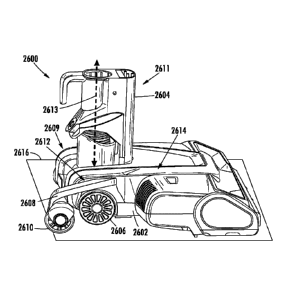
extended position and
the retracted position, the at least one wheel 3506 can be rotated 180 around
the first pivot
point 3510 (e.g., in a clockwise or a counter-clockwise direction).
Additionally, or
alternatively, when transitioning between the extended position and the
retracted position the
at least one wheel 3506 can be rotated less than or greater than 180 around
the first pivot point
3510 (e.g., in a clockwise or a counter-clockwise direction). For example,
when in the retracted
position, the at least one wheel 3506 can be rotated around the first pivot
point 3510 such that
a floor facing surface 3514 of the main body 3502 extends transverse to a
surface to be cleaned
3516 (e.g., a floor).
[0119] FIGS. 37 and 38 show a perspective view of a surface cleaning head
3700, which may
be an example of the surface cleaning head 2200 of FIG. 22. As shown, the
surface cleaning
head 3700 includes a main body 3702, a neck 3704 pivotally coupled to the main
body 3702,
at least one stabilizer 3706, and at least one wheel 3708 rotatably coupled to
the at least one
stabilizer 3706. The neck 3704 is configured to pivot side-to-side and between
a storage
position (e.g., as shown in FIG. 37) and an in-use position (e.g., as shown in
FIG. 38). When
the neck 3704 transitions from the storage position to the in-use position,
the at least one
stabilizer 3706 urges the at least one wheel 3708 from an extended position
(e.g., as shown in
FIG. 37) towards a retracted position (e.g., as shown in FIG. 38).
[0120] As shown, the neck 3704 includes at least one protrusion 3710
configured to engage
(e.g., contact) a swivel 3712 pivotally coupled to the main body 3702 of the
surface cleaning
head 3700. The protrusion 3710 is configured to cause the swivel 3712 to pivot
in response to
the neck 3704 being transitioned between the storage and in-use positions. The
swivel 3712 is
configured to urge the stabilizer 3706 along a track 3714 such that the at
least one wheel 3708
is transitioned between the extended and retracted positions in response to
the neck 3704 being
transitioned between the storage and in-use positions.
[0121] The swivel 3712 can be biased such that the swivel 3712 urges the
stabilizer 3706
towards the main body 3702 of the surface cleaning head 3700. In other words,
the swivel can
18
CA 03113028 2021-03-16
WO 2020/061285
PCT/US2019/051889
be configured to urge the at least one wheel 3708 towards the retracted
position. For example,
the swivel 3712 can be biased by a spring (e.g., a torsion spring, a
compression spring, an
extension spring, and/or any other spring).
[0122] Additionally, or alternatively, the stabilizer 3706 can be coupled to a
biasing
mechanism (e.g., a spring such as a torsion spring, a compression spring, an
extension spring,
and/or any other spring). For example, as shown in FIGS. 39 and 40, an
extension spring 3900
can be coupled to a main body 3902 of a surface cleaning head 3901 and a
stabilizer 3906 such
that, as the stabilizer 3906 is urged along a track 3914 in a direction away
from the main body
3902 of the surface cleaning head 3901, the extension spring 3900 is extended.
As the
extension spring 3900 extends, the extension spring 3900 exerts a force on the
stabilizer 3906
that urges the stabilizer 3906 towards the main body 3902 of the surface
cleaning head 3901.
[0123] FIG. 41 shows a perspective view of a portion of the main body 3702,
wherein an upper
portion of the main body 3702 is shown as being transparent for purposes of
clarity. FIG. 42
shows another perspective view of the portion of the main body 3702 shown in
FIG. 41. As
shown, the swivel 3712 is configured to pivot about a pivot axis 4100 that
extends transverse
(e.g., perpendicular) to a direction of forward travel. In other words, the
pivot axis 4100
extends substantially parallel to a wheel rotation axis 4102. As shown, the
wheel rotation axis
4102 is vertically spaced apart from the pivot axis 4100. In some instances, a
torsion spring
can be configured to exert a force on the swivel 3712 (e.g., the torsion
spring can extend around
the wheel rotation axis 4102).
[0124] FIG. 43 shows a cross-sectional view of a surface cleaning head 4300,
which may be
an example of the surface cleaning head 102 of FIG. 1. As shown, the surface
cleaning head
4300 includes a single stabilizer 4302 having a plurality of wheels 4304
coupled thereto. The
stabilizer 4302 is configured to transition between an extended and a
retracted position in
response to a neck 4303 transitioning between a storage and an in-use
position. As shown, the
stabilizer 4302 is configured to engage a track 4306 (e.g., a T-slot) that
extends along a bottom
surface 4308 of the surface cleaning head 4300. In some instances, and as
shown, the track
4306 can be defined in a main body 4310 of the surface cleaning head 4300.
[0125] FIGS. 44 and 45 show a schematic view of a surface cleaning head 4401,
which may
be an example of the surface cleaning head 102 of FIG. 1. As shown, the
surface cleaning head
4401 includes a stabilizer 4400 configured to transition between an extended
position (e.g., as
shown in FIG. 44) and a retracted position (e.g., as shown in FIG. 45). The
stabilizer 4400 can
include a plurality of links 4402. The links 4402 are pivotally coupled to
each other such that
stabilizer 4400 can transition between the extended position and the retracted
position. As
19
CA 03113028 2021-03-16
WO 2020/061285
PCT/US2019/051889
such, the stabilizer 4400 may generally be referred to as being a scissor
mechanism. As shown,
at least one wheel 4404 is coupled to the stabilizer 4400 (e.g., a distal most
one of the plurality
of links 4402) such that as the stabilizer 4400 is transitioned between the
extended and retracted
positions, the wheel 4404 is urged between an extended positioned (e.g., as
shown in FIG. 44)
and a retracted position (e.g., as shown in FIG. 45).
[0126] FIGS. 46 and 47 show a schematic view of a surface cleaning head 4600,
which may
be an example of the surface cleaning head 102 of FIG. 1. As shown, the
surface cleaning head
4600 includes a stabilizer 4602 configured to transition between an extended
position (e.g., as
shown in FIG. 46) and a retracted position (e.g., as shown in FIG. 47). As
shown, the stabilizer
4602 includes a lever 4604 configured to pivot about a pivot point 4606 in
response to a neck
4608 transitioning between an in-use position (e.g., as shown in FIG. 46) and
a storage position
(e.g., as shown in FIG. 47). As shown, as the neck 4608 transitions between
the in-use and
storage positions, a protrusion 4610 coupled to the neck 4608 engages (e.g.,
contacts) the lever
4604 such that the lever 4604 is caused to pivot about the pivot point 4606.
As the lever 4604
pivots, the lever 4604 urges a plunger 4612 along a track 4614. The plunger
4612 can be
coupled to at least one wheel 4616 such that the plunger 4612 urges the at
least one wheel 4616
between an extended position (e.g., as shown in FIG. 46) and a retracted
position (e.g., as
shown in FIG. 47).
[0127] FIG. 48 shows a side view of a surface cleaning head 4800, which may be
an example
of the surface cleaning head 102 of FIG. 1. As shown, the surface cleaning
head 4800 includes
a main body 4802, a neck 4804 pivotally coupled to the main body 4802, and a
stabilizer 4806
configured to transition between an extended and retracted position. As shown,
the stabilizer
4806 includes a pivot arm 4808 pivotally coupled to the main body 4802 such
that, as the pivot
arm 4808 pivots about a pivot point 4810, the pivot arm 4808 urges a plunger
4812 along a
track 4814. The pivot arm 4808 may be biased (e.g., using a spring) such that
the pivot arm
urges the plunger 4812 towards the main body 4802 of the surface cleaning head
4800. As
such, the neck 4804 may include a protrusion 4816 configured to engage (e.g.,
contact) the
pivot arm 4808 such that the plunger 4812 moves along the track 4814 in
response to
transitioning the neck 4804 between a storage and in-use position. As also
shown, at least one
wheel 4818 can be coupled to the plunger 4812 such that the at least one wheel
4818 transitions
between extended and retracted positions in response to the neck 4804 being
transitioned
between the storage and in-use positions.
[0128] FIGS. 49 and 50 show a schematic example of a stabilizer 4900, which
may be an
example of the stabilizer 114 of FIG. 1, coupled to a portion of a main body
4902 of a surface
CA 03113028 2021-03-16
WO 2020/061285
PCT/US2019/051889
cleaning head 4904. The stabilizer 4900 can include one or more struts 4906
pivotally coupled
to the main body 4902 and a wheel 4908. The wheel 4908 can be a main wheel of
the surface
cleaning head 4904. As shown, when the stabilizer 4900 is in the retracted
position (e.g., as
shown in FIG. 49) the one or more struts 4906 may extend generally parallel to
a surface of the
main body 4902 of the surface cleaning head 4904 and, when the stabilizer is
in the extended
position (e.g., as shown in FIG. 50), the struts 4906 may extend in a
direction away from and
behind the main body 4902.
[0129] FIG. 51 shows a schematic example of a surface cleaning head 5100,
which may be an
example of the surface cleaning head 102 of FIG. 1. As shown, the surface
cleaning head 5100
includes a stabilizer 5102 pivotally coupled to a neck 5104 of the surface
cleaning head 5100.
As shown, the stabilizer 5102 is configured to pivot between an extended and a
retracted
position (both positions being illustrated in FIG. 51 for purposes of
clarity). When in the
retracted position, the stabilizer 5102 extends generally parallel to a
longitudinal axis 5106 of
the neck 5104 and, when in the extended position, the stabilizer 5102 extends
in a direction
away from the neck 5104 and towards a surface to be cleaned (e.g., a floor).
In some instances,
the stabilizer 5102 can be configured to be removably coupled to the neck
5104, which may
facilitate use of the stabilizer 5102 between multiple surface treatment
apparatuses (e.g.,
vacuum cleaners).
[0130] FIGS. 52 and 53 show a schematic view of an example of a stabilizing
system
configured to improve the stability of a vacuum cleaner 5200. As shown, a
suction body 5202
(e.g., having a suction motor and dust cup) of the vacuum cleaner 5200 is
configured to slide
along a wand 5204 in a direction of a surface cleaning head 5206 such that a
location of a center
of mass of the vacuum cleaner can be positioned closer to the surface cleaning
head 5206. As
shown, the wand 5204 can be received at least partially within a flexible hose
5208. The
flexible hose 5208 extends along the suction body 5202.
[0131] An example of a surface cleaning head may include a main body, a neck
pivotally
coupled to the main body, a stabilizer, and a linkage pivotally coupled to the
main body and
the stabilizer. The linkage may be configured to cause the stabilizer to
transition between an
extended position and a retracted position in response to a pivotal movement
of the neck.
[0132] In some instances, the neck may include a protrusion configured to
engage at least a
portion of the linkage. The protrusion may be configured to urge the linkage
to pivot in
response to the pivotal movement of the neck. In some instances, the linkage
may include a
pivot arm and a plunger. The pivot arm may define a channel for receiving the
plunger. In
some instances, the plunger is configured to slide within the channel in
response to the pivotal
21
CA 03113028 2021-03-16
WO 2020/061285
PCT/US2019/051889
movement of the neck. In some instances, the stabilizer may include a wheel.
In some
instances, the surface cleaning head includes a plurality of stabilizers,
wherein each stabilizer
extends along a respective one of a first axis and a second axis. In some
instances, the first
axis may extend transverse to the second axis such that a separation distance
between the
stabilizers increases with increasing distance from the main body. In some
instances, the main
body may include an opening from which the stabilizer extends. In some
instances, the opening
may be disposed between a top surface of the main body and a main wheel. In
some instances,
at least a portion of the stabilizer may extend over at least a portion of the
main wheel.
[0133] An example of a vacuum cleaner may include a wand and a surface
cleaning head. The
surface cleaning head may include a main body, a neck, a stabilizer, and a
linkage. The neck
may be configured to receive the wand. The neck may be pivotally coupled to
the main body
such that the wand is configured to transition between a storage position and
an in-use position.
The linkage may be pivotally coupled to the main body and the stabilizer. The
linkage may be
configured to cause the stabilizer to transition between an extended position
and a retracted
position in response to a pivotal movement of the neck.
[0134] In some instances, the neck may include a protrusion configured to
engage at least a
portion of the linkage. The protrusion may be configured to urge the linkage
to pivot in
response to the pivotal movement of the neck. In some instances, the linkage
may include a
pivot arm and a plunger. The pivot arm may define a channel for receiving the
plunger. In
some instances, the plunger may be configured to slide within the channel in
response to the
pivotal movement of the neck. In some instances, the stabilizer may include a
wheel. In some
instances, the surface cleaning head may include a plurality of stabilizers,
wherein each
stabilizer extends along a respective one of a first axis and a second axis.
In some instances,
the first axis may extend transverse to the second axis such that a separation
distance between
the stabilizers increases with increasing distance from the main body. In some
instances, the
main body may include an opening from which the stabilizer extends. In some
instances, the
opening may be disposed between a top surface of the main body and a main
wheel. In some
instances, at least a portion of the stabilizer may extend over at least a
portion of the main
wheel.
[0135] While the principles of the invention have been described herein, it is
to be understood
by those skilled in the art that this description is made only by way of
example and not as a
limitation as to the scope of the invention. Other embodiments are
contemplated within the
scope of the present invention in addition to the exemplary embodiments shown
and described
herein. Modifications and substitutions by one of ordinary skill in the art
are considered to be
22
CA 03113028 2021-03-16
WO 2020/061285
PCT/US2019/051889
within the scope of the present invention, which is not to be limited except
by the following
claims.
23