Note: Descriptions are shown in the official language in which they were submitted.
I
TITLE OF THE INVENTION
CALIBRATION ADAPTOR BRACKET, APPARATUS AND METHOD
FIELD OF THE INVENTION
[0001]The present invention relates to a calibration adaptor bracket,
apparatus and
method. In particular, the present application relates to adaptors for
connecting a
force gauge to a control interface such as a yoke, stick, sidestick, rudder
pedal or
stab trim, in particular for use in a flight simulator or aircraft, and an
apparatus and
method for calibrating a simulated control interface such as a yoke, stick,
sidestick,
rudder pedal or stab trim in a flight simulator or aircraft.
BACKGROUND TO THE INVENTION
[0002]Vehicle simulators such as those for simulating the operation of an
aircraft
have been developed to provide a realistic analogue of the vehicle being
simulated
without the dangers inherent in having such a vehicle operated by a novice or
under
extreme conditions. As the realism of the simulators has improved, they have
become an indispensable component in the certification of vehicle operators
such
as pilots. In order to ensure that a given simulator meets the requisite
realism such
that they can be used as part of a certification program, the operation of
various
components must be measured versus a preapproved certification standard and,
as
necessary, the components must be recalibrated. In particular, systems such as
sidesticks and stab trims, which provide an instantaneous force feedback to
the
operator where the amount of force is an indication of the current state of a
component of the vehicle being operated (such as the flaps, ailerons and
elevators
on an aircraft) are required to provide a simulated force feedback that
reproduces
the levels of force feedback as would be experienced by the operator during
actual
operation.
Date Recue/Date Received 2021-03-30
2
[0003] Methods for measuring the force feedback of a sidestick and stab trim
during
operation of the simulator are known in the art. One drawback of these methods
is
that the measurements are not readily reproducible from time to time and
simulator
to simulator.
SUMMARY OF THE INVENTION
[0004]In order to address the above and other drawbacks, there is provided an
adaptor for positioning a force gauge relative to a control interface in a
flight
simulator or aircraft. The force gauge comprises a gauge handle and a gauge
connector, the control interface being moveable in at least one of a back-and-
forth
direction and a side-to-side direction, the adaptor comprising a housing
positionable
adjacent the control interface, said housing comprising a first surface
configured to
snugly receive a predetermined surface of the control interface, and a second
surface comprising a first housing connector configured for connection to the
gauge
connector such that pressure is exertable on the control interface by the
force gauge
in a first direction of measurement aligned with at least one of the back-and-
forth
direction and the side-to-side direction.
[0005]There is also provided a kit for measuring a force feedback of a control
interface in a flight simulator or aircraft, the control interface moveable in
a back-
and-forth direction to change one of a pitch and a yaw of the simulator and in
a side-
to-side direction to change a roll of the simulator. The kit comprises a force
gauge
comprising a gauge handle, a gauge attachment portion and a first direction of
measurement, and a housing positionable adjacent the control interface, the
housing comprising a first inner surface configured to snugly receive a
predetermined surface of the control interface and a second surface comprising
a
first point of attachment configured for attachment to the gauge attachment
portion
such that the first direction of measurement is aligned with one of the back-
and-forth
direction and the side-to-side direction.
Date Recue/Date Received 2021-03-30
3
[0006]Additionally, there is provided a method for testing a force feedback of
a
control interface in a flight simulator, the control interface being moveable
in at least
one of a back-and-forth direction to change a pitch or a yaw of the simulator
and in
a side-to-side direction to change a roll of the simulator. The method
comprises
placing an adaptor comprising a first point of attachment adjacent the control
interface, connecting a force gauge to the first point of attachment such that
a first
direction of measurement of the force gauge is aligned with one of the back-
and-
forth direction and the side-to-side direction, and moving a gauge handle
portion of
the force gauge in the first direction of measurement, thereby causing the
force
gauge to measure the force feedback generated by the control interface in the
first
measurement direction.
[0007] Furthermore, there is provided an assembly for measuring a force
feedback
of a stab trim in a flight simulator or aircraft, the stab trim comprising a
trim wheel
comprising a shaft receiving aperture arranged along an axis of the trim
wheel. The
assembly comprises an elongate shaft configured for insertion into the
aperture and
comprising a shaft axis, a handle arranged substantially radially to the shaft
axis,
and a load cell interconnecting the shaft and the handle wherein the load cell
is
configured for measuring a torque between the handle and the shaft.
[0008]Also, there is provided a method of testing a stab trim in a cockpit
simulator
or aircraft, the stab trim comprising a trim wheel comprising a shaft
receiving
aperture arranged along an axis thereof. The method comprises interconnecting
a
shaft to a handle wherein the shaft comprises a shaft axis and the handle is
arranged
substantially radially to the shaft axis, inserting the shaft into the
aperture, operating
the simulator, and measuring a torque between the handle and the shaft.
Date Recue/Date Received 2021-03-30
4
BRIEF DESCRIPTION OF THE DRAWINGS
[0009] Figure 1A provides a rear right raised perspective view of an adaptor
bracket
in accordance with a first illustrative embodiment of the present invention;
[0010] Figure 1B provides a front plan view of an adaptor bracket in
accordance with
a first illustrative embodiment of the present invention;
[0011] Figure 1C provides a rear plan view of an adaptor bracket in accordance
with
a first illustrative embodiment of the present invention;
[0012] Figure 1D provides a top plan view of an adaptor bracket in accordance
with
a first illustrative embodiment of the present invention;
[0013] Figure lE provides a bottom plan view of an adaptor bracket in
accordance
with a first illustrative embodiment of the present invention;
[0014] Figure 1F provides a right plan view of an adaptor bracket in
accordance with
a first illustrative embodiment of the present invention;
[0015] Figure 1G provides a left plan view of an adaptor bracket in accordance
with
a first illustrative embodiment of the present invention;
[0016] Figure 2 provides an exploded perspective view of an adaptor bracket
and
sidestick assembly in accordance with a first illustrative embodiment of the
present
invention;
[0017] Figure 3A provides a rear right raised perspective view of an adaptor
bracket,
sidestick and force gauge assembly for measuring force feedback in a side-to-
side
direction in accordance with a first illustrative embodiment of the present
invention;
Date Recue/Date Received 2021-03-30
5
[0018] Figure 3B provides a rear right raised perspective view of an adaptor
bracket,
sidestick and force gauge assembly for measuring force feedback in a back to
front
direction in accordance with a first illustrative embodiment of the present
invention;
[0019] Figure 4 provides a partially exploded perspective view of an adaptor
bracket
and sidestick assembly in accordance with a second illustrative embodiment of
the
present invention;
[0020] Figure 5 provides a graph of results of a force measurement of a
control
column in accordance with an illustrative embodiment of the present invention;
[0021] Figure 6 provides a raised perspective view of an assembly for
measuring
torque in a stab trim in accordance with an illustrative embodiment of the
present
invention;
[0022] Figure 7 provides a raised perspective view of a stab trim with a shaft
and
adaptor bracket installed in accordance with an illustrative embodiment of the
present invention;
[0023] Figure 8A provides a raised right front perspective view of an adaptor
bracket
in accordance with an illustrative embodiment of the present invention;
[0024] Figure 8B provides a front plan view of an adaptor bracket in
accordance with
an illustrative embodiment of the present invention.
[0025] Figure 8C provides a side plan view of an adaptor bracket in accordance
with
an illustrative embodiment of the present invention.
[0026] Figure 8D provides a rear plan view of an adaptor bracket in accordance
with
an illustrative embodiment of the present invention.
Date recue / Date received 2021-11-08
6
[0027] Figure 8E provides a raised left rear perspective view of an adaptor
bracket
in accordance with an illustrative embodiment of the present invention.
[0028] Figure 9A provides a raised left front perspective view of an adaptor
bracket
in accordance with a third illustrative embodiment of the present invention;
[0029] Figure 9B provides a right rear front perspective view of an adaptor
bracket
in accordance with a third illustrative embodiment of the present invention;
and
[0030] Figure 10 provides a rear raised perspective view of an adaptor
bracket,
rudder pedal and force gauge assembly for measuring force feedback of a rudder
pedal in accordance with a third illustrative embodiment of the present
invention.
DETAILED DESCRIPTION OF THE ILLUSTRATIVE EMBODIMENTS
[0031]Referring now to Figure 1A, a first embodiment of an adaptor, generally
referred to using the reference numeral 10, will be described. The adaptor 10
comprises a housing 12 illustratively comprised of two complementary plastic
parts
or halves 14, 16. The first complementary half 14 and the second complementary
half 16 may be assembled together using a plurality of fasteners 18. In a
particular
embodiment each of the fasteners 18 comprises a bolt 20 inserted through a
respective bolt receiving bore 22 in a first of the complementary halves 14,
16 and
threaded into a respective one of a plurality of threaded inserts (not shown)
in a
second one of the two complementary halves 14, 16.
[00321 Still referring to Figure 1A, the housing 12 further comprises a first
point of
attachment 24 and a second point of attachment 26. Each point of attachment
24,
26 illustratively comprises a threaded receptacle 28.
[0033] Referring now to Figure 2 in addition to Figure 1A, each of the
complementary
halves 14, 16 comprises an outer shell 30 manufactured from a rigid material
such
Date Recue/Date Received 2021-03-30
7
as hard plastic or the like, and a liner 32 manufactured from a flexible
material such
as a soft plastic or the like. The inner surface 34 of each of the outer
shells 30 is
formed to receive the liner 32 in a snug fit and such that the liner 32 is
held snugly
against the inner surface 34. In a particular embodiment an adhesive (not
shown)
may be used to secure the liner 32 to a corresponding one of the outer shells
30 or
the liner 32 and a corresponding one of the outer shells 30 may be
manufactured
together as a unitary piece.
[0034]Still referring to Figure 2 in addition to Figure 1A, the liner 32 is
formed such
that when the complementary halves 14, 16 are assembled together by threading
for each one of the fasteners 18 the bolt 20 into the bore 22 via a washer 36
and a
threaded insert 38, a sidestick, or control interface, receiving space 40 is
defined
which is shaped to snugly receive a sidestick/control interface 42 such that
the
sidestick/control interface 42 is held securely within the sidestick receiving
space 40
by the complementary halves 14, 16. In this regard, the liner 32 of each of
the
complementary halves 14, 16 includes features such as a molded surface 46 or
the
like which is complementary to the shape of the sidestick/control interface
42, and
which ensures that each time the adaptor 10 is assembled about the
sidestick/control interface 42, the positioning of the adaptor 10 on the
sidestick/control interface 42 is consistently the same. Additionally, the
complementary halves 14, 16 may further comprise apertures 48 or the like
allowing
control buttons 50 and the like on the sidestick/control interface 42 to be
accessed.
[0035]Still referring to Figure 2, as known in the art the sidestick/control
interface
42 is moveable from a central axis A in both a back-and-forth (B-B) direction
which
for example controls the pitch of an aircraft (not shown) and a side-to-side
(C-C)
direction which for example controls the roll of the aircraft. The first point
of
attachment 24 and second point of attachment 26 are positioned on the outer
shell
30 of the housing 12 such that when the complementary halves 14, 16 are
assembled about the sidestick/control interface 42, the first point of
attachment 24
is aligned with the back-and-forth (B-B) direction, and the second point of
Date Recue/Date Received 2021-03-30
8
attachment 26 is aligned with the side-to-side (S-S) direction, the second
point of
attachment 26 being at right angles to the orientation of the first point of
attachment
24. Additionally, the first point of attachment 24 and the second point of
attachment
26 lie in the same plane, which is substantially normal to the axis A of the
sidestick/control interface 42. In a particular embodiment, an accelerometer
(not
shown) can for example be embedded in the outer shell 30 or the like. An
exemplary
embodiment of an accelerometer comprises a PhidgetSpatial 3/3/3 Precision
accelerometer/magnetometer/gyroscope.
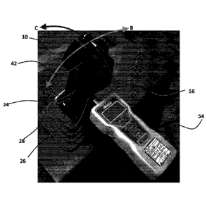
[0036] Referring now to Figure 3A and Figure 3B in addition to Figure 2, as
discussed above each of the first point of attachment 24 and the second point
of
attachment 26 comprises the threaded receptacle 28 (which illustratively
comprises
a threaded insert 52). In order to measure the force feedback, the
sidestick/control
interface 42 in the back and forth (B-B) direction or the side-to-side (C-C)
direction,
once the bracket 10 has been assembled to the sidestick/control interface 42,
a
force gauge 54 comprising a plunger 56 may be attached to the bracket 10 by
threading a threaded end 58 of the plunger 56 into the threaded receptacle 28
of a
respective one of the first point of attachment 24 and the second point of
attachment
26. As known in the art, the plunger 56 moves back and forth along a plunger
axis.
During measurement of the force feedback, the angle of the sidestick/control
interface 42 may be measured, for example by reading an output of an
accelerometer or by reading the angle from a simulator output.
[0037] Referring still to Figure 3A, the force feedback of the
sidestick/control
interface 42 in the side to side (C-C) direction, which is aligned with the
plunger axis,
can be measured by the force gauge 54 by threading the threaded end 58 of the
plunger 56 into the threaded receptacle 28 of the second point of attachment
26 and
pulling and pushing on the sidestick/control interface 42 in a side to side (C-
C)
direction using the force gauge 54 and such that pressure is exerted on the
sidestick
by movement of the force gauge 54. Movement of the sidestick/control interface
42
in a side-to-side direction is typically limited to a maximum deflection of
about 20
Date Recue/Date Received 2021-03-30
9
degrees in either direction.
[0038] Referring back to Figure 3B, the force feedback of the
sidestick/control
interface 42 in the back and forth (B-B) direction can be measured by the
force
gauge 54 by threading the threaded end 58 of the plunger 56 into the threaded
receptacle 28 of the first point of attachment 24 and pulling and pushing on
the
sidestick/control interface 42 in a back and forth (B-B) direction using the
force
gauge 54. Movement of the sidestick/control interface 42 in a back-and-forth
direction is typically limited to a maximum deflection of about 18 degrees in
either
direction.
[0039] Referring now to Figure 4, a second embodiment of an adaptor 60 will be
described. The adaptor 60 comprises a housing 62 illustratively comprised of
two
complementary plastic parts or halves 64, 66. The first complementary half 64
and
the second complementary half 66 may be assembled together using a plurality
of
fasteners 68. In a particular embodiment the fasteners each comprises a bolt
70
each of which is inserted through a respective bolt receiving bore 72 in a
first of the
complementary halves 64 and threaded into a respective one of a plurality of
threaded inserts (not shown) in a second one of the two complementary halves
64,
66. The two complementary halves 64, 66 are securable about the
sidestick/control
interface 42, which is held snugly therebetween for movement therewith.
[0040]Still referring to Figure 4, the housing 62 further comprises a first
point of
attachment 74 illustratively comprising a threaded rod 76. A force gauge 78
comprising a gauge handle 80 may be secured to the adaptor 60 via the rod 76.
The
force gauge 78 further comprises a sensor package 82 comprising one or more
sensors (not shown) such as a load cell or the like which measure forces
arising
between the gauge handle 80 and the first point of attachment 74. An exemplary
embodiment of a suitable load cell is a six (6) degree of freedom force-torque
sensor
which comprises strain gauges able to measure force along 3 orthogonal axes
and
produced by JR3 Multi-Axis Load Cell Systems. Illustratively, the sensor
package
Date Recue/Date Received 2021-03-30
10
82 measures both axial forces and torque forces vis-a-vis axis A 84 of the
point of
attachment 74. The elongate gauge handle 80 is illustratively secured to the
sensor
package 82 such that the gauge handle axis B is at right angles to the axis A.
[0041] Still referring to Figure 4, in operation with the force gauge 78
secured to the
housing 62 via the point of attachment 74 and the threaded rod 76, movement by
a
user of the gauge handle 80 in either a back and forth or side-to-side
direction
imparts measurable forces on the sidestick/control interface 42 in
respectively the
back and forth or side-to-side directions. The sensor package 82 reads these
imparted forces as axial 86 or torque 88 forces, which can be collected and
analysed
in order to calibrate the sidestick/control interface 42.
[0042] Referring now to Figure 5 in addition to Figure 4, output data 90 of a
force
measurement versus angle from upright of a control column in a back and front
(fore
and aft) movement is shown. Additionally, reference data 92 may also be
provided.
[0043] Referring now to Figure 6, an assembly 92 for measuring the feedback
force
of a stab trim is disclosed. The assembly 92 comprises a load cell 94 for
measuring
the torque between an elongate shaft 96 comprising a shaft axis A and a handle
98
arranged radially to the shaft axis A. The shaft 96 is mounted to the load
cell 94 by
a disk-shaped bracket 100 and a plurality of fasteners such as bolts 102 or
the like.
A conductive wire 104 can be provided to interconnect the electronics (not
shown)
of the load cell 94 with an external measuring device (also not shown), such
as a
multi-meter or the like, and via which measured torque values can be read.
[0044] Referring now to Figure 7, the shaft 96 is interconnectable with a stab
trim
106, which comprises a stab trim aperture 108 into which the shaft 96 can be
inserted. In this regard, the aperture 108 and the shaft 96 are complementary
in
shape such that when inserted, the shaft 96 rotates with the stab trim 106.
Illustratively, the shaft 96 is manufactured from a square rod and comprises a
Date recue / Date received 2021-11-08
11
square cross-section.
[0045] Referring to Figures 8A through 8F in addition to Figure 6, the bracket
100 is
sized to accord with the load cell 94 and comprises a shaft receiving aperture
110
for receiving the shaft 96 as well as a plurality of bores 112 via which the
bolts 102
can be inserted. The shaft receiving aperture 110 is illustratively sized and
shaped
to accept the square shaft 96 in a friction fit and for rotation therewith. An
embossment 114 is provided around the shaft receiving aperture 110 to ensure
that,
when the assembly 92 is mounted to a stab trim 106, a minimum spacing is
maintained to ensure that the assembly 92 is only in contact with the stab
trim via
shaft 96.
[0046] With reference to Figure 8F, in a particular embodiment a designation
of the
aircraft 116 for which the stab trim adaptor bracket 98 is intended can be
provided.
[0047] Referring back to Figure 6 and Figure 7, in operation, the force
feedback of
the stab trim 106 can be measured by interconnecting the load cell 94 with a
measuring device, inserting the shaft 96 of the assembly 92 into the stab trim
aperture 108 and moving the handle 98 while collecting readings via the
measurement device.
[0048] Referring now to Figure 9A and Figure 9B, an adaptor 118 in accordance
with a third illustrative embodiment will now be described. The adaptor 118
comprises an adaptor body 120 comprising a foot pedal/control interface
receiving
recess 122. A point of attachment 124 is provided for attaching the plunger of
a force
gauge (both not shown). Illustratively the point of attachment 124 comprises
an inner
surface (not shown) threaded to receive a threaded end of the plunger.
[0049] Referring now to Figure 10, a force gauge 126 comprising a plunger 128
is
secured to the adaptor 118 by threading the end of the plunger 128 into the
point of
attachment 124. Once assembled, the foot pedal receiving recess 122 is placed
Date Recue/Date Received 2021-03-30
12
over and pressed against a pedal/control interface 130 being tested
(illustratively a
rudder pedal in an aircraft simulator). The measured result is read off the
display
132 of the force gauge 126.
[0050] Although the present invention has been described hereinabove by way of
specific embodiments thereof, it can be modified, without departing from the
spirit
and nature of the subject invention as defined in the appended claims.
Date Recue/Date Received 2021-03-30