Note: Descriptions are shown in the official language in which they were submitted.
CA 03114037 2021-03-24
- 1 -
VARIABLE MOULDING JAW
Description
The invention relates to a moulding jaw unit for a corrugator.
Corrugators are used, for example, to manufacture corrugated pipes. In this
case, for example, a plastics material is introduced into the corrugator and
caused by overpressure and/or underpressure to come into contact with
shaping surfaces, which are formed on moulding jaw units of the corrugator
in order to thereby form the corrugated pipe. The corrugator usually
comprises a plurality of moulding jaw units that include the shaping surfaces.
The moulding jaw units typically move on the corrugator in a circulating
manner, so that depending on the rotational speed, number and size of the
moulding jaw units, one and the same moulding jaw unit repeatedly passes a
defined position on the corrugator after a predetermined period of time.
If the aim is to manufacture corrugated pipes having a uniform diameter but
different lengths, the corrugator may be equipped with moulding jaw units in
such a way that all the shaping surfaces of the moulding jaw units are
identical to one another. In this way, it is possible to manufacture an
endless
corrugated pipe having a uniform diameter. In a subsequent processing step,
this endless corrugated pipe may then be cut to the desired lengths.
If, on the other hand, the aim is to manufacture corrugated pipes which have
a variable diameter over their length, for example a region having an
enlarged diameter compared to the rest of the corrugated pipe, the
corrugator may then be equipped with moulding jaw units which allow
manufacture of corrugated pipe portions having a small diameter,
manufacture of corrugated pipe portions having an increasing diameter,
manufacture of corrugated pipe portions having a large diameter and
manufacture of corrugated pipe portions having a decreasing diameter.
Date Recue/Date Received 2021-03-24
CA 03114037 2021-03-24
- 2 -
However, due to the system, i.e. due to the operating principle of the
corrugator, it is possible to manufacture only an endless corrugated pipe, in
which the enlarged diameter occurs in a constant periodic sequence. If, for
example, corrugated pipes are desired which include exactly one portion
having an enlarged diameter, then these can only be manufactured in a
single length without generating relatively large amounts of material waste.
However, if the aim is to manufacture different corrugated pipes which, for
example, include a different number of portions having an enlarged diameter,
but the same overall length, it is laborious to reconfigure the fittings of
the
corrugator for each corrugated pipe.
Due to this high expenditure of time and costs for re-equipping a corrugator,
small series or even single unit production of specific corrugated pipes is
often not possible.
It is therefore the object of the present invention to provide a moulding jaw
unit for a corrugator, or a corrugator, which makes it possible to flexibly
adapt
a design of a corrugated pipe to be manufactured and to thereby reduce the
set-up costs of the corrugator.
This object is achieved in a first aspect by a moulding jaw unit for a
corrugator, comprising a moulding jaw attachment that includes a plurality of
mutually different shaping surfaces, the shaping surfaces being suitable for
imparting a predetermined shape to a material to be moulded, and a
moulding jaw base element on which the moulding jaw attachment is
arranged, wherein the moulding jaw attachment is mounted on the moulding
jaw base element so as to be displaceable relative thereto.
Because the moulding jaw attachment that includes the plurality of shaping
surfaces is displaceable relative to the moulding jaw base element, which is
held on the corrugator, a design of a corrugated pipe to be manufactured
Date Recue/Date Received 2021-03-24
CA 03114037 2021-03-24
- 3 -
may be changed without having to exchange a corresponding moulding jaw
unit, i.e. having to remove an entire moulding jaw unit from the corrugator,
as
is customary in one-piece moulding jaw units of the prior art. In the example
of a corrugated pipe described at the outset, in particular, which comprises a
portion having an enlarged diameter, a respective moulding jaw attachment
may have four shaping surfaces, namely a shaping surface for a corrugated
pipe portion having a first diameter, a shaping surface for a corrugated pipe
portion having an increasing diameter, a shaping surface for a corrugated
pipe portion having a decreasing diameter and a shaping surface for a
corrugated pipe portion having a second diameter which is larger than the
first diameter.
Depending on how the corrugated pipe to be manufactured is to be formed
by a respective moulding jaw unit, the moulding jaw attachment may be
displaced relative to the moulding jaw base element in such a way that the
corresponding shaping surface becomes part of the production chain of the
corrugated pipe, i.e. comes into contact with the material from which the
corrugated pipe is formed.
Instead of the four shaping surfaces described here, the moulding jaw
attachment may, of course, also include more or fewer shaping surfaces,
depending on the variety of products to be covered by a single moulding jaw
unit.
In a development of the invention, the moulding jaw attachment may be
displaceable transationally relative to the moulding jaw base element along
precisely one axis or displaceable rotationally about precisely one axis. With
respect to the first alternative, this may be implemented, for example, by
connecting the moulding jaw attachment to the moulding jaw base element
via a sliding and/or rolling means. For example, the moulding jaw attachment
may be connected to the moulding jaw base element via a dovetail
connection, so that the moulding jaw attachment may only be displaced back
Date Recue/Date Received 2021-03-24
CA 03114037 2021-03-24
- 4 -
and forth relative to the moulding jaw base element along the dovetail
connection (this direction may also be referred to as the "shaping surface
displacement direction").
The relative displacement between the moulding jaw attachment and the
moulding jaw base element in this case may be assigned a locking device
such as, for example, a latching device, it being possible, in particular, to
provide the same number of latch positions as shaping surfaces. The latching
device may, in particular, be arranged in such a way that each respective
central axis of the shaping surfaces assigned to a respective latching device
comes to rest at an identical position relative to the moulding jaw base
element when the latching device engages in such a way that this shaping
surface becomes part of the above-mentioned production chain. It may thus
be ensured that a central axis of a corrugated pipe to be manufactured
continues on without any significant offset even after the moulding jaw unit
has been switched to a different shaping surface.
In this case, the plurality of shaping surfaces on the moulding jaw attachment
may be arranged on the same surface. If, for example, the moulding jaw
attachment has a flat surface on its side opposite the sliding and/or rolling
means, then all of the shaping surfaces may be arranged on this flat surface.
The shaping surfaces may, in particular, be consecutive in the direction in
which the moulding jaw attachment is displaceable relative to the moulding
jaw base element. In addition, each of the above-mentioned central axes of
respective shaping surfaces may be orthogonal to this displacement direction
of the moulding jaw attachment relative to the moulding jaw base element.
Advantageously, the surface may extend substantially parallel to the
displacement direction of the moulding jaw attachment relative to the
moulding jaw base element, so that a depth extension of a respective
moulding jaw unit from the surface that includes the shaping surfaces to an
opposite end of the moulding jaw unit remains constant, regardless of the
Date Recue/Date Received 2021-03-24
CA 03114037 2021-03-24
- 5 -
positioning of the moulding jaw attachment relative to the moulding jaw base
element.
With respect to the second alternative mentioned above, this may be
implemented, for example, in that the moulding jaw attachment is rotatably
mounted on the moulding jaw base element.
The moulding jaw attachment in this case may have a polygonal cross
section and each of the plurality of shaping surfaces may be arranged on a
different surface of the polygonal moulding jaw attachment. A polygon may
advantageously be selected which has as many sides as there are mutually
differing shaping surfaces. For the example of four mutually different shaping
surfaces mentioned at the outset, a moulding jaw attachment having a
square cross section could therefore result. Depending on the desired design
of the corrugated pipe to be manufactured, the moulding jaw attachment may
be rotated in such a way that the corresponding shaping surface points to the
portion of the corrugator at which the corrugated pipe is formed.
In a second aspect, the present invention relates to a corrugator comprising a
plurality of moulding jaws, which comprises at least a plurality of moulding
jaw units, in particular moulding jaw units according to the invention,
wherein
each moulding jaw unit has a moulding jaw attachment which comprises a
plurality of mutually different shaping surfaces, wherein the shaping surfaces
are suitable for imparting a predetermined shape to a material to be moulded,
and comprises a moulding jaw base element on which the moulding jaw
attachment is arranged, wherein the moulding jaw attachment is mounted on
the moulding jaw base element so as to be displaceable relative thereto, and
a moulding jaw carrier on which the moulding jaw base elements are held.
It should already be mentioned at this point that the features and advantages
described with respect to the moulding jaw unit according to the invention
may also be used with respect to the corrugator according to the invention
Date Recue/Date Received 2021-03-24
CA 03114037 2021-03-24
- 6 -
and vice versa.
Moulding jaw attachments of moulding jaw units, which form parts of a mould
that defines a shape of a corrugated pipe to be manufactured, may preferably
be designed to be identical to one another. Thus, these two moulding jaw
attachments, which abut each other at a predefined point of the corrugator to
form the above-mentioned mould, may be displaced in the same direction
and by the same amount in order to include half-moulds that match each
other again, which are able to contact the material of the corrugated pipe to
be manufactured.
In one development of the present invention, the moulding jaw carrier may be
designed as a chain or as a guide device. The moulding jaw units may, in
particular, be connected to the moulding jaw carrier in a detachable manner.
The moulding jaw units held on the moulding jaw carrier may be operatively
mounted on the corrugator by the moulding jaw carrier so as to be
displaceable along a, for example horizontal, conveying direction. In the case
of the moulding jaw carrier designed as a chain, the moulding jaw units may
be actively displaced over the entire rotation thereof on the corrugator by
the
moulding jaw carrier, i.e. in every position of a respective moulding jaw unit
on the corrugator, a driving force may act on a respective moulding jaw unit
via the moulding jaw carrier, which may displace the moulding jaw unit on the
corrugator. In the case of the moulding jaw carrier designed as a guide
device, the moulding jaw units may only be driven portion by portion. For
example, the moulding jaw units may be engaged with the moulding jaw
carrier designed as a guide rail in such a way that they are displaceable only
along one axis of the guide rail. In this case, the moulding jaw units may
only
be driven passively, in particular at least in the region of the corrugator in
which the moulding jaw units abut against respective complementary
moulding jaw units, in order to form a mould for the corrugated pipe to be
manufactured. This means, a drive of the moulding jaw units along the
moulding jaw carrier may be arranged on a portion of the corrugator that
Date Recue/Date Received 2021-03-24
CA 03114037 2021-03-24
- 7 -
differs from the region of the manufacture of the corrugated pipe, for example
at the longitudinal ends of the corrugator or at the longitudinal ends of the
region at which the corrugated pipe is manufactured. The moulding jaw units
driven by this portion come into lateral contact with the respective adjacent,
non-driven moulding jaw units and push them through the moulding jaw
carrier. It may thus be ensured that, at least in the region in which the
moulding jaw units are passively pushed further, there is no gap, or at least
a
gap that is negligible in terms of the manufacture of the corrugated pipe,
present between laterally adjacent moulding jaw units.
This direction along which the moulding jaw units are displaced during the
production of a corrugated pipe or in which the corrugated pipe is
manufactured may also be referred to as the "production direction".
The moulding jaw attachment may be advantageously displaced relative to
the moulding jaw base element in the operating state of the moulding jaw unit
along a direction substantially orthogonal to a production direction of the
corrugator or rotatable about an axis substantially parallel to the production
direction of the corrugator. Corrugators that have a horizontal production
direction as well as corrugators that have a vertical production direction are
known from the prior art. Accordingly, a translational displacement direction
of a moulding jaw attachment may be vertical in a corrugator with a horizontal
production direction and horizontal in a corrugator with a vertical production
direction. In the case of a corrugator with a horizontal production direction,
an
axis of rotation of a moulding jaw attachment relative to a moulding jaw base
element may also be oriented horizontally, in particular, parallel to the
production direction. However, a right-angled orientation of the axis of
rotation to the direction of production is, of course, also conceivable. The
axis
of rotation may also be oriented orthogonally, i.e. vertically in the case of
a
corrugator with a horizontal production direction. The same applies here to a
corrugator with a vertical production direction.
Date Recue/Date Received 2021-03-24
CA 03114037 2021-03-24
- 8 -
The corrugator may comprise an adjustment device, which is adapted to
displace the moulding jaw attachment relative to the moulding jaw base
element by a predetermined amount. Depending on the design of the
moulding jaw unit or the type of displacement of the moulding jaw attachment
relative to the moulding jaw base element, the adjustment device may
displace or rotate a respective moulding jaw attachment relative to the
moulding jaw base element. As previously described with respect to the
moulding jaw unit according to the invention, a latching device may be
provided, which defines at least one position of the moulding jaw attachment
relative to the moulding jaw base element or holds it with a defined holding
force.
The adjustment device may be designed as at least one displaceable stop
with which a portion of the moulding jaw attachment comes into contact so
that the moulding jaw attachment is displaced relative to the moulding jaw
base element in accordance with the preset position of the stop. This stop
may, for example, be displaceable in the displacement direction of the
moulding jaw attachment or of the shaping surfaces. Furthermore, the stop
may be adapted to be displaceable step by step in such a way that each step
corresponds to a predetermined position of the moulding jaw attachment
relative to the moulding jaw base element coinciding, for example, with a
defined position of the latching device. In this case, the stop may interact
with
a respective moulding jaw attachment in such a way that a displacement of a
respective moulding jaw unit on the moulding jaw carrier transversely to the
stop causes the respective moulding jaw attachment to slide off the stop and
thus the displacement of the moulding jaw attachment up to the
predetermined position.
Alternatively or in addition, it may be provided that the adjustment device
may be adapted to be displaced over a predefined distance together with at
least one moulding jaw unit to be adjusted, so that, for example, no relative
movement takes place between the adjustment device and the respective
Date Recue/Date Received 2021-03-24
CA 03114037 2021-03-24
- 9 -
moulding jaw unit during the joint displacement. The adjustment device in this
case may be adapted to displace a respective moulding jaw attachment
relative to the moulding jaw base element in a desired manner. After this
displacement, the adjustment device may return to a start of the predefined
distance over which the adjustment device together with a respective
moulding jaw unit is displaced, in order in this way to set, for example, at
least one subsequent moulding jaw unit.
The adjustment device in this case may be designed as a plurality of
adjustment units, each adjustment unit being assigned to a moulding jaw
element, and each adjustment unit being adapted to displace the moulding
jaw attachment relative to the moulding jaw base element. In this way, an
interaction between a number of adjustment units of the adjustment device
and the distance over which the adjustment device together with the
moulding jaw units to be adjusted is displaced may, in particular, be selected
such that a first set of moulding jaw units, which are able to be adjusted
simultaneously by the adjustment device, and a second set of moulding jaw
units, which are able to be adjusted simultaneously immediately after the
adjustment of the first set of moulding jaw units, are directly consecutive.
In
this way, the adjustment device may be adapted to be able to engage with all
of the moulding jaw units of the corrugator that are assigned to this
adjustment device during a single rotation of the moulding jaw units on the
corrugator.
In one advantageous embodiment of the present invention, two moulding jaw
attachments, which together form a mould, may be provided with projections
and recesses which are adapted to engage with one another when the
moulding jaw attachments operatively abut one another. On the one hand,
this may ensure that small orientation inaccuracies between two shaping
surfaces forming a mould for a portion of the corrugated pipe to be
manufactured may be compensated for by means of an engagement of
respective projections and recesses. On the other hand, an adjustment
Date Recue/Date Received 2021-03-24
CA 03114037 2021-03-24
- 10 -
device may be provided at a position of the corrugator at which two opposing
moulding jaw attachments are already engaged with one another via their
respective projections and recesses, so that a displacement of one of the two
moulding jaw attachments causes a displacement of the respective other
moulding jaw attachment. Thus, for example, a single adjustment device for
the corrugator may be sufficient.
Alternatively or in addition, at least two moulding jaw attachments arranged
one after the other, in particular on the same moulding jaw carrier, as viewed
in a production direction of the corrugator, may be provided with projections
and recesses that are adapted to engage with one another when the
moulding jaw attachments operatively abut one another. That which is
described above for two opposing moulding jaw attachments may be similarly
applied here for two moulding jaw attachments arranged one after the other
or next to one another. The displacement of a comparatively large number of
moulding jaw attachments simultaneously relative to respective moulding jaw
base elements may be achieved by displacing a single moulding jaw
attachment, or at least a small number of moulding jaw attachments. This
may be particularly advantageous if such a "chain" of moulding jaw units or of
shaping surfaces of moulding jaw attachments not only have a predefined
sequence of shaping surfaces for a desired corrugated pipe in the course of
the shaping surfaces that contribute to the formation of the corrugated pipe,
but also have a series of successive and mutually matching shaping
surfaces, which are arranged on respective moulding jaw attachments above
or below the shaping surfaces, which contribute specifically to the formation
of the corrugated pipe.
This is to be illustrated with reference to an example. If, for example, a
corrugated pipe having a constant diameter is manufactured in an endless
manner, this may mean that all the shaping surfaces involved in the
manufacture of the corrugated pipe have the same diameter or are identical
to one another. If it is now desired to provide a portion having an enlarged
Date Recue/Date Received 2021-03-24
CA 03114037 2021-03-24
- 11 -
diameter at any point in time during the manufacture of the endless
corrugated pipe, a chain of laterally engaging moulding jaw attachments may
be displaced in such a way that the shaping surfaces of these moulding jaw
attachments previously not involved in the manufacture of the corrugated
tube take the place of the shaping surfaces previously involved in the
manufacture of the corrugated pipe. For example, this chain may consist of
four moulding jaw attachments or shaping surfaces, whereby, in
chronological sequence according to the manufacture of the corrugated pipe,
a first shaping surface defines a corrugated pipe portion having an increasing
diameter, a second and third shaping surface defines a respective corrugated
pipe portion having a constant, enlarged diameter and a fourth shaping
surface defines a corrugated pipe portion having a decreasing diameter.
Once the corrugated pipe portion having an enlarged diameter is
manufactured, the above-described chain of moulding jaw attachments may
again be displaced out of the row of shaping surfaces involved, so that an
endless corrugated pipe having a constant cross section may again be
manufactured, which is smaller compared to the portion having an enlarged
diameter.
This process may, of course, be repeated as desired and/or a plurality of
such "connectable" chains of moulding jaw attachments may be arranged in
order to be able to manufacture corrugated pipes having varying diameters in
a very flexible manner.
Such a "connection" of a corresponding chain of moulding jaw attachments
may advantageously take place on one side of the corrugator (and possibly
also on a mirrored opposite side of the corrugator), on which the moulding
jaw attachments assigned to such a chain of shaping surfaces are not
involved in the manufacture of the corrugated pipe.
It should be added at this point that the term "constant diameter of a
corrugated pipe" is intended to express that a diameter of a corrugated pipe
Date Recue/Date Received 2021-03-24
CA 03114037 2021-03-24
- 12 -
remains constant over a portion under consideration without taking into
account the changes in diameter resulting from the corrugation troughs and
crests of the wall of the corrugated pipe. For this purpose, it may be
irrelevant
whether the inside diameter, the outside diameter or an average diameter of
the corrugated wall of the corrugated pipe over the portion of the corrugated
pipe under consideration is used, as long as the wall thickness of the
corrugated pipe also remains uniform. The same naturally applies to portions
of the corrugated pipe having an increasing or decreasing diameter.
In a third aspect, the present invention relates to a method for changing a
shape of a corrugator defined by shaping surfaces, wherein the method
comprises the steps:
- providing a corrugator comprising
a plurality of moulding jaws, which comprises at least a plurality of moulding
jaw units, in particular moulding jaw units according to the invention,
wherein
each moulding jaw unit comprises
a moulding jaw attachment which includes a plurality of mutually different
shaping surfaces, wherein the shaping surfaces are suitable for imparting a
predetermined shape to a material to be moulded, and
a moulding jaw base element on which the moulding jaw attachment is
arranged, wherein the moulding jaw attachment is mounted on the moulding
jaw base element so as to be displaceable relative thereto, and
a moulding jaw carrier on which the moulding jaw base elements are held;
- driving the moulding jaw base elements such that they move along a
conveying direction;
- driving at least one moulding jaw attachment during the movement
thereof in the conveying direction, so that the moulding jaw attachment is
displaced from a first position, which is assigned to a first shaping surface,
into a second position, which is assigned to a second shaping surface.
It should be noted that all of the features and advantages described for the
moulding jaw unit according to the invention and/or the corrugator according
Date Recue/Date Received 2021-03-24
CA 03114037 2021-03-24
- 13 -
to the invention apply to the method according to the invention and vice
versa. For this reason, explicit reference is made at this point to the above
description of the corrugator according to the invention and possibly also the
moulding jaw unit according to the invention with regard to the mode of
operation and advantages of the method according to the invention.
The invention is described in greater detail below on the basis of exemplary
embodiments with reference to the accompanying drawings, in which
Figure 1 shows a perspective view of a first embodiment of a
moulding jaw unit according to the invention;
Figure 2 shows a side view of the moulding jaw unit according
to
the invention from Figure 1;
Figure 3 shows a perspective view of a second embodiment of a
moulding jaw unit according to the invention;
Figure 4 shows a schematic top view of a corrugator according
to the invention;
Figure 5 shows a cross-sectional view of the corrugator from
Figure 4 according to the invention; and
Figures 6a through 6d show a schematic sequence in accordance with
the method according to the invention for changing a
shape of a corrugator defined by shaping surfaces.
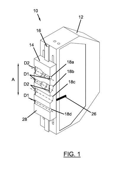
In Figure 1, a moulding jaw unit according to the invention is generally
provided with the reference numeral 10. The moulding jaw unit 10 comprises
a moulding jaw base element 12 and a moulding jaw attachment 14. The
moulding jaw attachment 14 is mounted on the moulding jaw base element
Date Recue/Date Received 2021-03-24
CA 03114037 2021-03-24
-14-
12 in such a way that it may only be displaced along the axis A. In the
exemplary embodiment shown in Figure 1, the moulding jaw attachment 14 is
connected to the moulding jaw base element 12 via a dovetail connection 16.
The moulding jaw attachment 14 here includes four shaping surfaces 18a
through 18d, wherein the shaping surface 18a is able to define one half of a
mould for a portion of a corrugated pipe to be produced, in which the
corrugated pipe is tapered from a larger outer diameter D2 to a smaller outer
diameter Dl. This depends, of course, on which side of a corrugator this
moulding jaw unit 10 is used and in which direction the moulding jaw unit 10
is driven with respect to the manufacture of a corrugated pipe. Thus, in
another application, the shaping surface 18a could also be adapted to
expand a corrugated pipe having an outer diameter D1 to a larger outer
diameter D2. With respect to the first preceding specific application, the
shaping surface 18b of the moulding jaw attachment 14 shown here is
adapted to provide half of a mould for a portion of a corrugated pipe, in
which
the outer diameter of the corrugated pipe expands from the outer diameter
D1 to the larger outer diameter D2. The shaping surface 18c forms half of a
mould which is adapted to form a portion of a corrugated pipe having a
constant outer diameter D2, and the shaping surface 18d forms half of a
mould which is adapted to form a portion of a corrugated pipe having a
constant outer diameter Dl.
The profile of the shaping surfaces 18a through 18d is again clearly apparent
in the side view of Figure 2. It is further apparent that arranged on both
sides
of the dovetail connection 16 are recesses 20 in the moulding jaw base
element 12, in which, for example, a latching device 22 is arranged, which is
adapted to hold the moulding jaw attachment 14 at predefined positions
relative to the moulding jaw base element 12 in such a way that a
displacement of the moulding jaw attachment 14 relative to the moulding jaw
base element 12 is only allowed by overcoming a predetermined holding
force.
Date Recue/Date Received 2021-03-24
CA 03114037 2021-03-24
- 15 -
The holding positions of the latching device 22 or the moulding jaw
attachment 14 relative to the moulding jaw base element 12 are arranged
here in such a way that in each holding position, i.e. when the latching
device
22 engages, a corresponding central axis 24a through 24d, which is assigned
to a respective shaping surface 18a through 18d, is arranged at the same
position relative to the moulding jaw base element 12 as a corresponding
central axis 24a through 24d of a shaping surface 18a through 18d, which
was previously arranged at this point when the latching device 22 was
engaged. Such a position is indicated by way of example in Figure 1 by the
marking 26, at the height of which a corresponding central axis 24a through
24d may be arranged when the latching device 22 is engaged. This may
correspond, for example, to a height at which a respective one of the shaping
surfaces 18a through 18d may be involved in the manufacture of a
corrugated pipe.
In the embodiment shown in Figures 1 and 2, all of the shaping surfaces 18a
through 18d are arranged on a common flat surface 28, the main direction of
extension of which runs parallel to the axis A.
Figure 3 shows a moulding jaw attachment 14' of a second embodiment of a
moulding jaw unit according to the invention.
Like the moulding jaw unit 10 of the first embodiment, the features and
advantages of which are explicitly referred to with respect to the second
embodiment of a moulding jaw unit according to Figure 3, so too does the
second embodiment of the moulding jaw attachment 14' include the four
shaping surfaces 18a through 18d. Each of the shaping surfaces 18a through
18d is arranged on a separate surface 30'a through 30'd. According to the
number of shaping surfaces 18a through 18d, four separate surfaces 30'a
through 30'd are provided here in such a way that the moulding jaw
attachment 14' has a substantially square cross section.
Date Recue/Date Received 2021-03-24
CA 03114037 2021-03-24
- 16 -
The moulding jaw attachment 14' is connected to a moulding jaw base
element (not shown) in such a way that the moulding jaw attachment 14' is
rotatable about an axis of rotation B relative to the moulding jaw base
element. Accordingly, a respective shaping surface 18a through 18d may
point away from the moulding jaw base element and may interact with a
complementary shaping surface 18a through 18d of an opposing moulding
jaw attachment 14' in order to form a mould for a corrugated pipe to be
manufactured.
Figure 4 shows a top view of a corrugator according to the invention, which is
generally designated by the reference symbol numeral 100. The corrugator
100 here comprises a plurality of moulding jaw units 10 according to the
invention, each of which includes a moulding jaw base element 12 and a
moulding jaw attachment 14, as was described above with reference to
Figures 1 and 2.
The moulding jaw base elements 12 are connected to a moulding jaw carrier
102, which drives the moulding jaw units 10 at the two longitudinal ends of
the corrugator 100 shown on the left and right in Figure 4, for example via a
gear, along the direction of rotation shown by the arrows C, in such a way
that the moulding jaw units 10 located on the longitudinal sides of the
corrugator 100, which may be located here in a guide rail of the moulding jaw
carrier 102, are pushed forward by the moulding jaw units 10 driven by the
moulding jaw carrier 102.
That which is described for the upper part 100a of the corrugator 100 shown
in Figure 4 naturally applies in an analogous manner to the lower part 100b
of the corrugator 100 shown in Figure 4.
As is apparent in the centre of Figure 4, moulding jaw units 10 of the upper
part 100a of the corrugator 100 and moulding jaw units 10 of the lower part
Date Recue/Date Received 2021-03-24
CA 03114037 2021-03-24
- 17 -
100b of the corrugator 100 converge on a side shown on the left in Figure 4
until their surfaces 28 abut one another. Shaping surfaces 18a through 18d
complementary to one another form a mould at this point, which defines a
portion of a corrugated pipe 104 to be manufactured. A plastics material, for
example, is now introduced into this mould which, by applying a vacuum to
channels (not shown) running through the shaping surfaces 18a through 18d,
is made to adapt to the contour of the shaping surfaces 18a through 18d.
According to the choice of interacting shaping surfaces 18a through 18d, a
profile of the corrugated pipe 104 is defined accordingly.
The arrow R in Figure 4 indicates the direction in which the corrugated pipe
104 produced leaves the corrugator 100 (also called the "production
direction"). The corrugated pipe 104 in this case includes portions 106 having
a first diameter D1, portions 108 having a diameter increasing from a first
diameter D1 to a second diameter D2, which is larger than the first diameter
D1, portions 110 having a constant diameter D2 and portions 112 having a
diameter decreasing from diameter D2 to diameter Dl. As previously stated
above, the portion 106 of the corrugated pipe 104 is formed by two mutually
abutting shaping surfaces 18d, the portion 108 of the corrugated pipe 104 by
two mutually abutting shaping surfaces 18b, the portion 110 of the corrugated
pipe 104 by two mutually abutting shaping surfaces 18c and the portion 112
of the corrugated pipe 104 is formed by two mutually abutting shaping
surfaces 18a, into which appropriate plastics material is introduced.
In each of the parts 100a and 100b of the corrugator 100, an adjustment
device 114 is shown, which is formed here from four adjustment units 116.
Each of the four adjustment units 116 is adapted to engage with a moulding
jaw unit 10 or with a moulding jaw attachment 14 of a moulding jaw unit 10 in
order to displace the moulding jaw attachment 14 relative to a respective
moulding jaw base element 12 attached to the moulding jaw carrier 102. In
the exemplary embodiment shown in Figure 4, the moulding jaw attachments
14 are displaced relative to the moulding jaw base elements 12 along an axis
Date Recue/Date Received 2021-03-24
CA 03114037 2021-03-24
- 18 -
A vertical to the plane of the sheet (see in this regard also Figure 1 or
Figure
5).
The adjustment device 114 is also adapted to be displaced together with the
moulding jaw units 10 over a distance S in order to be able to carry out a
corresponding adjustment of the moulding jaw attachments 14 relative to the
moulding jaw base elements 12 during the transport of the moulding jaw units
by the moulding jaw carrier 102, without influencing the transport
movement of the moulding jaw units 10 in the process. The moulding jaw
10 units 10, with which the adjustment device 114 is just engageable, may
be
regarded as a first set 118 of moulding jaw units 10, whereas moulding jaw
units 10, which are engageable with the adjustment device 114 after the first
set 118 of moulding jaw units 10, may be regarded as a second set 120 of
moulding jaw units 10. Once a corresponding adjustment of the moulding jaw
attachments 14 has been carried out, the adjustment device 114 may be
moved back into the initial position shown in Figure 4.
The line V-V in Figure 4 indicates a section line, a corresponding sectional
view being shown in Figure 5, which will be described in greater detail below.
Two mutually abutting moulding jaw attachments 14 are shown in the centre
of Figure 5, which together form a mould 122, by means of which a portion of
the corrugated pipe 104 to be manufactured may be formed. Paths 124,
which are shown as a dot-dash line, via which a negative pressure may be
applied to the mould 122, extend to the sides of the mould 122 shown on the
left and right in Figure 5.
The moulding jaw attachments 14 of the moulding jaw units 10 shown in the
centre in Figure 5 are displaced maximally downwards relative to their
respective moulding jaw base elements 12. The moulding jaw base elements
12 of the moulding jaw units 10 are slidably mounted in respective moulding
jaw carriers 102 of the corrugator 100, as indicated by way of example by the
Date Recue/Date Received 2021-03-24
CA 03114037 2021-03-24
- 19 -
reference numeral 126.
On the left and right outer sides of the corrugator 100 shown in Figure 5, one
moulding jaw unit 10 is shown in each case, of which the moulding jaw
attachments 14 are situated in different positions relative to their
respective
moulding jaw base elements 12. The moulding jaw attachment 14 of the
moulding jaw unit 10 shown on the left in Figure 5 is in a position that is
substantially identical to the two moulding jaw attachments 14 of the
moulding jaw units 10 shown in the centre of Figure 5, whereas the moulding
jaw attachment 14 of the moulding jaw unit 10 shown on the right in Figure 5
is shifted maximally upwards along the axis A.
The adjustment devices 114 or the adjustment units 116 shown on the left
and right in Figure 5 are described by way of example below using the
adjustment unit 116 shown on the right in Figure 5.
The adjustment unit 116 includes an engagement device 128, which is
adapted to engage with a respective corresponding engagement portion 130
of a moulding jaw attachment 14 so as to allow a joint displacement of a slide
132 of the adjustment unit 116 on which the engagement device 128 is
attached, together with a respective moulding jaw attachment 14 along the
axis A. The slide 132 is driven here via a drive unit 134 of the adjustment
unit
116, the drive unit 134 driving a gear 136 here, which in turn engages with a
toothing 138 of the slide 132 in such a way that a rotation of the gear 136
causes a displacement of the slide 132 along the axis A.
The adjustment unit 116 is also adapted to interact with a latching device 22
of the moulding jaw unit 10, thus allowing a relative displacement of a
moulding jaw attachment 14 relative to the associated moulding jaw base
element 12.
All the drive units 134 of the adjustment devices 114 are connected to a
Date Recue/Date Received 2021-03-24
CA 03114037 2021-03-24
- 20 -
control unit (not shown) which is adapted to send corresponding control
commands to the drive units 134 in order to drive respective slides 132 by a
desired distance.
If the moulding jaw unit 10 shown on the left in Figure 5 were also shifted
into
the position of the moulding jaw unit shown on the right in Figure 5, the two
moulding jaw attachments 14 would converge in such a way that their
respective shaping surfaces 18d would become part of the production chain
of the corrugated pipe 104, i.e. a portion 106 of the corrugated pipe 104
would thus be formed.
In Figures 6a through 6d, four stages of an adjustment process according to
the invention are now shown, the view of Figures 6a through 6d
corresponding to a viewing direction according to an arrow D shown in
Figures 4 and 5.
A plurality of moulding jaw attachments 14 may be seen in Figures 6a
through 6d, only three of which are provided with the reference numeral 14
by way of example in each of Figures 6a through 6d. Furthermore, a dot-
dash line K is shown, which indicates the above-mentioned "chain" or
"production chain", along which respective shaping surfaces of the moulding
jaw attachments interact in order to produce a corrugated pipe 104.
In order to be able to better explain the progression of Figures 6a through
6d,
the four moulding jaw attachments with which the adjustment units 116 are
engaged are referred to (from left to right) as the first moulding jaw
attachment 14a, second moulding jaw attachment 14b, third moulding jaw
attachment 14c and fourth moulding jaw attachment 14d. The moulding jaw
attachments 14a through 14d, which may also be referred to as a first set
118 of moulding jaw attachments 14, have just been engaged by respective
adjustment units 116 in Figure 6a. As indicated by the arrow T, all of the
moulding jaw attachments 14 are displaced further in the direction of the
Date Recue/Date Received 2021-03-24
CA 03114037 2021-03-24
- 21 -
arrow T.
In Figure 6b, the first set 118 has been displaced further in the direction of
the arrow T (here by the width of two moulding jaw attachments 14).
Accordingly, the adjustment device 114 has also been displaced by this
distance along the travel path S of the adjustment device 114 on the
corrugator 100 together with the moulding jaw attachments 14a through 14d.
Furthermore, the first moulding jaw attachment 14a has been displaced by
one step, upwards in the drawing in Figure 6b. The second moulding jaw
attachment 14b has been displaced upwards by two steps by the
corresponding adjustment unit 116. The third moulding jaw attachment 14c
has been displaced downwards by one step. The fourth moulding jaw
attachment 14d has been displaced upwards by one step. According to the
arrangement of the shaping surfaces 18a through 18d on the respective
moulding jaw attachments 14a through 14d, the shaping surfaces of the first
through fourth moulding jaw attachments 14a through 14d that are displaced
into the production chain K form (in this order) portions 110, 110, 112 and
106 of a corrugated pipe 104.
In Figure 6c, the first set 118 of moulding jaw attachments 14a through 14d
has been displaced further in the direction of arrow T by the width of a
moulding jaw attachment 14. The adjustment units 116 of the adjustment
device 114 have disengaged from the moulding jaw attachments 14a through
14d and the slides 132 of the adjustment units 116 are displaced into a fully
retracted initial position.
An initial position of the adjustment device 114 is now shown in Figure 6d,
the adjustment device 114 or the adjustment units 116 thereof being adapted
to engage with a second set 120 of fifth to eighth moulding jaw attachments
14e through 14h. The subsequent method steps are repeated in a manner
analogous to the first set 118 of moulding jaw attachments 14, corresponding
to a desired shaping of the corrugated pipe 104 by the respective shaping
Date Recue/Date Received 2021-03-24
CA 03114037 2021-03-24
- 22 -
surfaces 18a through 18d of the respective moulding jaw attachments 14e
through 14h.
Date Recue/Date Received 2021-03-24