Note: Descriptions are shown in the official language in which they were submitted.
METHODS AND SYSTEMS FOR IMPLANTABLE MEDICAL DEVICES AND
VASCULARIZATION MEMBRANES
This International Application claims the benefit of priority of U.S.
Provisional
Patent Application Serial No. 62/735,697, filed September 24, 2018, and U.S.
Provisional
Patent Application Serial No. 62/736,244, filed September 25, 2018.
FIELD
Embodiments of the present disclosure relate to the field of membrane coatings
for
implantable medical devices, implantable medical devices having at least one
surface coated
with a membrane, and methods for inhibiting fibrotic capsule formation and the
formation
of vascular structures at a medical implant device site. Embodiments of the
present
disclosure also relate to implantable devices that provide enhanced
vascularization with a
host, and immune-isolated devices which provide for encapsulation of live
cells.
BACKGROUND
Irnmuno-isolation devices designed for delivering a cellular medical therapy
-- featuring an outer vascularizing membrane and an inner allogenic cell
protective membrane
are manufactured with relatively difficult and labor-intensive processes. The
outer
vascularizing membrane generally has a three-dimensional structure that is
sufficiently open
to allow cells to penetrate the membrane material. This is usually laminated
or otherwise
affixed to an inner immune-isolation membrane that has pores that are
sufficiently large to
allow biological macromolecules to freely diffuse across the membrane but
prevent cells of
the recipient from crossing the membrane. These membranes are typically
manufactured
separately, laminated together, and then affixed to an implantable medical
device as part of
1
Date Recue/Date Received 2022-10-04
CA 03114197 2021-03-24
WO 2020/068852
PCT/US2019/052728
an assembly process. The separate step by which the membranes are joined
together is time
consuming and difficult, and renders the membrane subject to pealing,
delamination and
decomposition. When such pealing or delamination occurs, the tissue
surrounding the
implant can react to the implanted medical device by creating local regions of
fibrosis. If
the implantable device contains living cells that produce a therapeutic
product, the local
fibrosis can lead to an environment that results in impairment of function of
the encapsulated
cells and possibly death of those cells. Therefore, a means of creating an
outer vascularizing
membrane in combination with an inner, denser immune-isolation layer that
cannot
delaminate or peal apart from the device would allow the development of a more
stable and
predictable implant with better function.
The implantable medical device field remains in need of coatings and/or
membranes
that overcome these and other limitations associated with multi-layer,
laminated, membrane
constructs.
The number of patients suffering from Type I and Type II diabetes is estimated
to
affect about 4.6% of the world's population. Pancreas transplantation and
islet
transplantation are known methods for treating diabetes. However, pancreas and
islet
transplantation into diabetic patients is limited to a small percent of
patients who might
benefit from either procedure due to the lack of available human pancreata or
pancreatic
islets. With the recent development of insulin secreting cells derived from
human stem
cells, there is a possibility of treating patients with insulin dependent
diabetes through
transplantation. However, such cells would be subject to rejection by the
immune system
of the recipient patient unless immunosuppressive drugs were administered to
the patient
for the rest of their life. Alternatively, insulin secreting cells could be
provided with an
immuno-isolating implantable device and placed in the diabetic patient to act
as an insulin
delivery source.
2
CA 03114197 2021-03-24
WO 2020/068852
PCT/US2019/052728
Accordingly, studies for improving the viability of islet cells and islet
progenitor cells in a
ported immune-isolated implantable device are being conducted.
Since the islet transplantation protocol was established, clinical islet
transplantation
has been regarded as a treatment method for treating type 1 diabetics.
However, the low
.. engraftment success of transplanted islet cells remains a major cause of
failure of long-term
blood sugar regulation. Upon implantation, it is necessary for islet cells to
be successfully
engrafted through revascularization and blood flow regulation within a few
days after
transplantation. However, transplanted islet cells are exposed to a state with
low vascular
density and insufficient oxygen conditions, making it difficult to achieve
normal
.. engraftment of islet cells and the ability to achieve regulated insulin
secretion in the patient.
Currently, there are limited means and materials to effectively implement live
cell
containing immuno-isolation devices in vivo. Limitations associated with
supply of
adequate oxygen levels to encapsulated cells, sufficient nutrient levels to
the encapsulated
cells, insufficient vascularization of the implanted device and immune
response to the
implant, remain barriers to use of cell-containing implantable devices.
SUMMARY
Embodiments of the present disclosure provide a single layer gradient
membrane,
such as a non-naturally occurring single layer polymeric or similar material
gradient
membrane, wherein the single layer gradient membrane comprises a gradually
transitioning
gradient of material density and pore sizes in the micron size range. The
single layer
gradient membrane is characterized by continuously variable and differing pore
sizes
throughout the thickness of the single layer gradient membrane (Fig. la).
As used herein, the terms "gradient" and "gradient membrane" relate to a
polymeric
or similar material membrane having an internal structure comprising gradually
changing
3
CA 03114197 2021-03-24
WO 2020/068852
PCT/US2019/052728
pore sizes. The pore sizes of the gradually changing pore sizes of the
gradient membrane
are in the micron size range. As used herein, the term "micron" is used in the
singular and
plural to refer to micrometer and/or micrometers.
Single component membranes of the present disclosure (i.e., single layer
membranes
with a non-laminated structure) are characterized by a continuous gradient of
gradually
transitioning pore size, from a tight or dense intertwined structure region
(having relatively
small pore size) to a more open or loose intertwined fiber network (having a
relatively larger
pore size). Progression from the inner structure/surface to the outer
structure/surface of the
membrane evidences a transition of gradient to a more open structural
configuration.
Likewise, the pores gradually transition from smaller to larger, such as from
about 0.1 to
about 1.0 micron at one surface (such as an inside surface), towards the outer
surface of the
membrane, having a membrane region comprising a gradient of pore size from
about 2.0 to
approximately 100 micron (or in some embodiments, from about 5 to about 15
micron)
through the single layer, component membrane.
One of ordinary skill in the art will readily understand the term "pore size"
as used
herein. Additionally, one of ordinary skill in the art will understand and
recognize different
methods and devices for measuring and evaluating pore sizes. In some
embodiments, pore
sizes of embodiments of the present disclosure are evaluated, measured, and/or
confirmed
by the use of a bubble point test method or a scanning electron microscope.
Single layer gradient membranes of the present disclosure comprise various
materials, including those deemed appropriate by a person skilled in the art
for an
implantable medical device. For example, membranes of the present disclosure
are
contemplated as being prepared from a polymeric material. In such embodiments,
the single
layer gradient membrane is prepared from such polymeric materials as:
polysulfone,
polyarylethersulfone (PAES), polyethersulfone (PES), cellulose ester
(cellulose acetate,
4
CA 03114197 2021-03-24
WO 2020/068852
PCT/US2019/052728
cellulose triacetate, cellulose nitrate), nanocellulose, regenerated cellulose
(RC), silicone,
polyamide (nylon), polyimide, polyamide imide, polyamide urea, polycarbonate,
ceramic,
titanium oxide, aluminum oxide, silicon, zeolite (alumosilicate),
polyarylonitrile (PAN),
polyethylene (PE), low density polyethylene (LDPE), polypropylene (PP),
___________________ polytetrafluoroethylene (P [FE), polyvinylidene
fluoride (PVDF), polyvinylchloride (PVC),
polypiperazine amide, polyethylene terephthalate (PET), polycarbonate (PC),
polyurethane,
and any complex or mixtures thereof. In particular embodiments, a single layer
gradient
membrane comprises of a polymeric material comprising polytetrafluoroethylene
(PTFE).
In certain preferred embodiments, PTFE is provided for at least a
vascularizing layer of
devices of the present disclosure. Additional materials are contemplated as
being provided
in membranes and implants of the present disclosure in addition to or in lieu
of PTFE.
In some embodiments, a gradient membrane comprises an electro-spun polymeric
membrane, such as an electrospun PTFE membrane that is applied directly to a
surface, such
as a surface of an implantable medical device. Implantable medical devices of
the present
disclosure are contemplated as comprising an internal chamber of live cells.
No separate
assembly steps are required to provide a protective layer/film to an internal
chamber of an
implantable medical device in which live cells may be contained, as the single
layer gradient
membrane is capable of protecting the cells from immune attack, while
simultaneously
permitting nutrient flow/oxygen to contained live cells, owing to the
appropriate gradient
pore size provided by the single layer gradient membrane. Single layer
gradient membranes
of the present disclosure also provide for a slightly larger pore size within
the membrane
region extending to the other surface (e.g., outer surface) of the single
layer membrane, thus
providing a surface suitable for vascularizing the outer surface of the
implantable medical
device in a host.
5
In various embodiments, single layer, gradient membranes are formed with phase
inversion, interfacial polymerization, solution coating and/or phase
deposition methods.
These and other processes are described in Baker (Baker, R. Membrane
Technology and
applications. John Wiley & Sons, 2004).
In various embodiments, electrospinning is provided as a process to control
fabricating a fibrous mat of changing and defined density in a single layer
membrane
construction.
It is an aspect of the present disclosure to provide materials and processes
that
provide for the elimination of delamination problems of prior fabricated
techniques having
a bi-layer membrane structure. In addition, the method by which the single
layer, gradient
membranes are prepared are preferable to other 2-step processes, that require
a separate
lamination and/or fusing step between two separately fabricated membranes,
such as that
described in US Patent 6,060,640.
In various embodiments, implantable medical devices are provided that comprise
at
least one surface upon which a single layer membrane material having a
gradient structure
is applied. The surface is contemplated as comprising the surface of an
implantable medical
device, such as an implantable device that has a lumen comprising living cells
(e.g. stem
cells). The gradient pore size of the single layer membrane permits the
passage of desired
molecules, such as nutrients in an in vivo environment, to move through the
membrane and
to encapsulated living cells in the lumen of an implantable medical device.
The single layer
gradient membrane also permits passage of molecules out of the lumen of an
implantable
medical device, such as a therapeutic product/agent that is contained in the
lumen of the
implantable medical device. In this manner, the gradient single layer membrane
permits the
6
Date Recue/Date Received 2022-10-04
CA 03114197 2021-03-24
WO 2020/068852
PCT/US2019/052728
implantable medical device to act in releasing therapeutic product/agents out
of the
implantable medical device and available for absorption in the patient.
In various embodiments, membranes are employed as coatings on any or all
surfaces
of an implantable medical device. Some surfaces of an implant device may be
devoid of a
membrane, For example, surfaces at which fibrotic mass formation is not a
significant
occurrence are contemplated as being devoid of membranes. Additional surfaces
that are
devoid of a membrane include, for example, surfaces at a sonic weld joint on
an access port
of an implantable medical device.
In one embodiment, a single layer gradient membrane to reduce overall fibrosis
comprises pores having a size of about 0.1 to about 100 micron (or, from about
0.1 or about
5 micron to about 15 micron). In some embodiments, an implantable medical is
provided
that comprises a lumen comprising living cells. The single layer gradient
membrane
comprises a pore size that does not interfere with the passage of molecules
(such as insulin
produced by contained islet cells) out of a lumen chamber (having its own
chamber lining),
and out of the implantable medical device into the body. In this regard, the
membrane is
sufficiently thin so as to allow rapid diffusion of molecules out of the
implantable medical
device. As another example, a single layer gradient membrane is provided on
some surfaces
of a component of a multi-component implantable medical device and not on
other surfaces.
In certain embodiments, implant systems are provided that comprise a surface
having a single layer gradient membrane, such as a membrane comprising a
polymeric
material. By way of example, the polymeric material is contemplated as
comprising P1TE,
where the PTFE membrane comprises a gradient of pore sizes. This single layer
PTFE
gradient membrane is provided to the external surface of the implantable
medical device
system. The outer side (host vasculature inter-facing) of the PTFE gradient
membrane
enables cellular ingress (greater than 1 micron to about 15 micron), and the
PITE gradient
7
CA 03114197 2021-03-24
WO 2020/068852
PCT/US2019/052728
membrane titrates down in relative pore size to an appropriate size that would
prohibit
cellular ingress (about 0.1 micron to about 1 micron) into the cell-containing
inner chamber
of the implantable medical device. The pore size of the PTFE gradient membrane
renders
the implantable medical device immuno-isolating for the implanted cells.
In further embodiments, implant systems comprise a surface with an electrospun
PTFE gradient membrane combining immunoisolation and vascularization features
as
described above are provided. An electrospun PTFE multielement layer comprises
relatively larger fibers, of a size sufficient to inhibit fibroblast layer
formation. This feature
may take the form of a final, outer gradient layer comprising multiple strands
to form thick
fibers of about 25 to about 200 micron in diameter. With such larger fibers
randomly
oriented on the outer surface of the gradient membrane, the layer serves as a
surface to
inhibit fibroblasts from forming a fused fibrotic layer.
In another aspect, a manufacturing process and/or method is provided for
producing
an implantable medical device comprising an immune-isolation chamber of live
cells. In
one embodiment, the method comprises a series of steps that provide for
application of a
single layer gradient membrane, such as an electrospun PTFE single layer
gradient
membrane, to a surface of the implantable medical device. The method can also
provide a
single step electrospun deposition process wherein a material, such as PTFE,
is extruded
onto a surface in a manner such as to create increasingly less dense and
therefore larger pore
size, regions in the single layer membrane plus a modification to the gradient
membrane
that will form large diameter (about 25 micron to about 200 micron) randomly
oriented
fibers on the surface of the gradient pore membrane that assist in preventing
the foimation
of tight layers of fibroblasts in the host tissue region close to the
implantable medical
device/tissue interface. Figure 2A shows a representation of the gradient
membrane with
the large pore surface that induces vascularization facing up. Although the 10
micron to 15
8
CA 03114197 2021-03-24
WO 2020/068852
PCT/US2019/052728
micron pore surface will induce the formation of close vascular structures,
areas of fibroblast
layering can form above the developing vascularized interface. Figure 2B shows
the
gradient membrane with a random network of large diameter fibers anchored to
the top of
the gradient surface. These fibers serve to break up any layer of closely
packed fibroblasts
that may start to form and will further allow additional vascular structures
to form. The
fibers may be a non-woven mesh such as polyester or they may be made of
electrospun
PTFE fibers cast parallel to each other to form relatively larger diameter
fibers. Such fibers
can be made as a separate network of random fibers and then applied to the
gradient
membrane or, in the case of electrospun gradient membranes, the
electrospinning process
can be programmed to switch to a different mode of laying down fibers once the
thickness
of the gradient membrane has been reached. The new mode of electrospinning
creates
relatively larger fibers at the surface of the gradient membrane that are
contiguous with, or
non-contiguous with, the gradient membrane.
In some embodiments, methods of the present disclosure do not require, and
advantageously eliminates an assembly step for sealing two separate component
membrane
layers together. Prior constructs required a separate step of this nature to
achieve the
fabrication of a membrane coating having varying pore size. The present single
layer
gradient membranes are absent a sharp demarcation zone within the membrane
separating
areas or regions of differing pore size.
Various embodiments of the present disclosure contemplate the provision of
membranes of the present disclosure on an implantable device. The outer
membrane region
of the membrane may be further defined as having a surface that is closest to
the exterior of
the membrane, and would be expected, in some embodiments, to interface with
the in vivo
environment of an animal or human when provided on the surface of an
implantable medical
device. The inner membrane region of the membrane is further defined as having
a surface
9
CA 03114197 2021-03-24
WO 2020/068852
PCT/US2019/052728
that is closest to the interior of the membrane, and in some embodiments forms
an interface
with a surface or an internal lumen of an implantable medical device. Such an
internal
lumen would be designed to contain living cells or a therapeutic agent. A
transitional
gradated membrane region resides between the inner membrane region and outer
membrane
region in some embodiments of the present disclosure.
In some embodiments, the inner membrane region comprises a gradient of
relatively
smaller pore size, such as a gradient of from about 0.1 to about 1 micron pore
size. In some
embodiments, the outer membrane region is characterized as a having a gradient
of
relatively larger pore size, such as a gradient of from about 2 micron to
about 100 micron
(or about 5 to about 15 micron). In this embodiment, the transitional gradient
membrane
region between the inner and outer region is characterized as having a gradual
gradient of
pore size of between about 1 micron at an interface closest to the inner
membrane region,
and about 5 micron at an interface closest to the outer membrane region.
In some embodiments, a single layer electrospun gradient membrane is provided
that
further includes a gradient membrane region having a pore size of between
about 15 and
about 50 micron at a region closest to an interface with the outer membrane
region as
described above, or alternatively a gradient pore size of up to about 190
micron.
In some embodiments, the membrane is further defined as a single layer immuno-
isolation electrospun PTFE gradient membrane, the single layer membrane
comprising
gradient individual membrane regions within the single layer, one membrane
region having
a graduated pore size of about 0.1 to about 1 micron, a membrane region having
a pore size
of about 2 micron to about 100 micron (or about 15 micron), and a
transitioning membrane
region there between having a gradient pore size of about 5 micron to about 50
micron (or
alternatively between about 5 micron to about 15 micron).
CA 03114197 2021-03-24
WO 2020/068852
PCT/US2019/052728
The single layer membrane can be constructed to further include an outer layer
comprising a woven or non-woven layer. This outer layer may or may not be
attached to
the single layer gradient membrane. This layer may comprise a non-woven
polyester fiber
mesh, or be fabricated to include thicker fibers comprising a non-woven mesh.
The outer
layer would comprise a pore size greater than about 200 micron. In some
embodiments, the
outer layer comprises randomly dispersed strands of electrospun polymeric
material, such
as PTFE, or a non-woven immune-compatible material as polyester.
In another embodiment, an immuno-isolation implantable medical device is
provided that comprises a surface having thereon the single layer immuno-
isolation
electrospun gradient membrane as described herein. This single layer immuno-
isolation
electrospun gradient membrane may comprise electrospun PTFE, and the single
layer
immune-isolation electrospun gradient membrane will comprise an inner and an
outer
membrane region having a gradient pore size. The membrane regions, for
example, may
comprise a first innermost PTFE membrane region having a gradient pore size
ranging from
between about 0.1 to about 1 micron, an outer gradient PTFE membrane region
having a
pore size ranging from about 5 micron to about 50 micron (or about 5 to about
15 micron),
and a transition region having a gradual gradient pore size of about 1 micron
to about 15 (or
10) micron.
In some embodiments, an immuno-isolation implantable medical device is
provided
that comprises an inner lumen, and the inner lumen comprises a population of
live cells or
therapeutic agents. By way of example, the live cells may comprise human
cells, such as
islet cells, naturally occurring primary cells, cell lines, genetically
engineered cells, stem
cell derived cells, or a combination thereof
In some embodiments, the single layer gradient membrane is provided over the
entire surface of an implantable medical device.
11
CA 03114197 2021-03-24
WO 2020/068852
PCT/US2019/052728
In yet another embodiment, a method of manufacture of a single layer immuno-
isolation electrospun gradient membrane comprising a polymeric material is
provided. This
single layer immuno-isolation electrospun gradient membrane comprises membrane
regions
having a gradient pore size produced in a single layer by an electrospinning
process,
wherein a single membrane layer is created having several gradient membrane
regions of
different pore size so as to create a continuous and gradual gradient of
increasing pore size
through the single layer membrane. In one embodiment, the single layer will
have an inner
membrane region having a gradient pore size of about 0.1 to about 1 micron, an
outer
membrane region having a gradient pore size of about 5 micron to about 50 (or
alternatively
about 5 micron to about 15 micron); and a transition membrane region there
between having
a gradient pore size of about 5 micron to about 40 micron (or alternatively
about 5 micron
to about 10 micron).
The single layer immuno-isolation electrospun gradient membrane preferably
comprises a relatively thin thickness. In some embodiments, the thickness of
the single
layer gradient membrane is between about 20 micron and 150 micron or any
subrange
between 20 and 150 micron. The single layer immuno-isolation electrospun
gradient
membrane does not comprise an abrupt demarcation between the various gradient
inner and
outer membrane regions or at the interface with the transition membrane
region. The
continuous gradient of pore size though out the single layer gradient membrane
structure
presents superior and more uniform diffusion properties, and facilitates a
more predictable
and steady release of therapeutic agents and compounds that may be included
within a lumen
of an implantable medical device comprising the single layer gradient
membrane. Such
features present significant advantages and avoids the problems associated
with prior
implantable structures, such those structures described in US Patent
6,060,640.
12
CA 03114197 2021-03-24
WO 2020/068852
PCT/US2019/052728
In various embodiments, the present disclosure provides implantable devices
having
a number of improved characteristics and features. In some embodiments, an
implantable
device is provided that possesses a unique configuration that facilitates a
maximization of
surface area available for vascularization by a host animal. The configuration
of the implant
.. device, in some embodiments comprises a multi-component structure,
comprising one or
more individual element members and a hub and/or a manifold, wherein the
individual pod
elements are in communication with the hub and/or manifold. In this regard,
means are
provided that permit multiple of the individual element members of the device
to
communicate with at least one common component of the device, such as a hub or
a
.. manifold. In this manner, and where the individual member element comprises
an internal
lumen, access to the lumen of each individual element member and the hub
and/or manifold
is provided.
Implant devices of the present disclosure comprise unique configurations and
may
be implanted in a manner that optimizes the number of devices per unit area of
a surgical
site in a patient. The configuration of the implantable device can be
optimized to the shape
and size of a particular surgical site into which it is being inserted into a
patient, such as to
closely pattern the surgical insertion site created by a blunt tissue
dissection. The design of
the individual element members of the implantable device also permits enhanced
access to
the interior lumen areas of the element members, making the device readily
available to
.. addition of an agent of interest suitable for delivery to a host, such as a
therapeutic agent, or
alternatively, to the loading of a live cell population to the lumen.
In various embodiments, implantable devices of the present disclosure comprise
a
manifold having a means to provide communication from one or more element
members
(i.e. immuno-isolation devices) to a hub of the device. The means to
communicate between
the manifold and an element member may be implemented to selectively transfer
oxygen,
13
CA 03114197 2021-03-24
WO 2020/068852
PCT/US2019/052728
therapeutic agents, nutritional agents, electrical signals, electrical power
or multiple
combinations thereof to the element member. In certain embodiments,
communication
means from the manifold to the element member(s) comprise a tube or catheter
to supply
gas or liquids to the element member, such as specifically to a lumen of an
element member.
This connecting communication means may also be utilized as part of the
implant device to
connect electrical wires or circuit leads to transmit electrical signals or
power, or to
communicate combinations of materials to the lumen of the element member.
In some embodiments, the hub or central portion of an implant comprises a
component within which the implant device may house an oxygen generator, pump
for
therapeutic agents or nutritional agents, reservoir(s), electronics, power
supply or
combinations thereof, and to communicate to element members via the manifold.
The manifold and hub of implant devices of certain embodiments impart a number
of distinct functions to the device. For example, the manifold provides a
pathway to
communicate between the element member (immuno-isolation device) and a hub.
The hub,
in some embodiments, provides a structure in which functional elements of the
implant
device may be housed. In some embodiments, the implant device comprises both a
manifold
and a hub, and the manifold is in communication with the hub. Configurations
of the device
implant are also provided where an element member is in communication with
more than
one hub and a (or more than one) manifold, such as through one or more
connection means
.. between the manifold and the lumen of an element member. In some
embodiments, the
implant device will comprise element members having multiple access ports and
lumens.
In some embodiments, the hub and/or manifold comprises a surface which
comprises
a vascularizing material. By way of example, such a vascularizing material may
comprise
an immune-isolating membrane, for example, a 5 gm nominal pore size expanded
PTFE
14
CA 03114197 2021-03-24
WO 2020/068852
PCT/US2019/052728
membrane. This membrane serves to reduce the inflammatory response of a host
once the
implant device is provided under the skin (subcutaneously) in the animal.
The advantages of the presently disclosed immune-isolation implantable devices
include a maximization of surface area presented by the device available for
vascularization
by a host. In particular, implantable devices or portions thereof that
comprise an immuno-
isolation device present surface area that may be vascularized by the host
when implanted.
This structure maximizes vascularization of the device as a whole in the
animal. Implantable
devices of the present disclosure comprise at least one manifold and a hub,
the manifold
being in communication with one or more pod members. Pod members comprise at
least
one lumen providing a communication pathway. In some embodiments, each lumen
comprises at least one distinct chamber within the lumen.
In some embodiments, pod elements of the present disclosure are (i) tapered at
the
proximal end to minimize the overlap of multiple implant devices in
communication with
the manifold, (ii) tapered at one end to enable multiple pod elements having a
lumen to be
.. implanted with at least one cross-section surface of the pod element (and
the lumen
contained therein) to be in contact with the in vivo host environment upon
implantation, at
a single surgical site, (iii) tapered at one end to minimize the distance from
any adjacent pod
member, (iv) shaped to have an overall shape that is similar to that created
by a common
blunt surgical instrument during an implantation procedure, (v) shaped to
optimize and
minimize the length of the communication means (such as a tube or catheter)
that is provided
to establish access and/or communication between the manifold and a pod
member, or two
or more pod members implanted in a single surgical site.
The multi-component implantable device may be further described as an immuno-
isolation device. In some embodiments, each pod member comprises a tapered end
having
.. at least one access port in communication with at least one lumen of a pod.
The taper enables
CA 03114197 2021-03-24
WO 2020/068852
PCT/US2019/052728
multiple devices to be implanted (i) in a stack one-on-top-the-other
configuration, (ii) edge
to edge in a fan configuration, (iii) overlapping to expose a portion of the
top and bottom to
the in vivo environment of the host. At least one proximal port of each pod
member may be
in communication with a manifold, so as to provide access of the manifold to
the lumen of
each pod member. Other ports can be located at each element member of the
immune-
isolation device. These additional ports may be used to facilitate additional
access to the
lumen of the pod member. The individual pod members and their internal volumes
are filled
with an identified amount of desired cells or therapeutic agents. The desired
cell population,
for example, may comprise cells that are designed to secrete a therapeutic
product. By way
of example, the cells may comprise a population of cells enriched for islet
cells capable of
secreting insulin through the membrane of the lumen and into the in vivo
environment of
the host, in response to circulating glucose levels in the host.
Alternatively, the chambers
may be empty and a drug may be introduced through injection or pumping into a
hub for
distribution to the multiple attached chambers.
In various embodiments, one or more pod members of immuno-isolation devices of
the present disclosure comprise an electro-chemical or optical sensor provided
in
communication with the hub and the manifold. Communication means of the
manifold
including, but not limited to, electrical wiring, pumps, and other features,
are operable to
transmit power, a pre-pulse signal, a measurement signal, and/or oxygen to and
from the
sensor. A pre-pulse signal is contemplated at least in embodiments comprising
electro-
chemical sensors to initiate a measurement. Devices of the present disclosure
comprising
one or more pod members and porous membranes provide means to transport fluids
or
agents from vascular structures adjacent to a device surface to the
encapsulated sensor.
Alternatively, one or more lumens of the present disclosure are operable to
disperse
one or more therapeutic agents to a host. For example, a lumen of pod may be
provided
16
CA 03114197 2021-03-24
WO 2020/068852
PCT/US2019/052728
with an active agent, such as an active biological agent, insulin, Factor
VIII, Factor IX, HGH
hormone, or proteins from the hub via the manifold. The active agent will then
be released
through the lumen of the pod of the implant device and be rapidly dispersed
through the
vascular structures formed surrounding the implant device.
In the above manner, and through an interconnection of the pod ports, the
immune-
isolation device implanted into the soft tissue of an animal, such as a human,
may also be
configured to communicate with other implanted immune-isolation devices,
device
manifolds, catheters, or other desired materials through one or more of the
available device
pod ports.
In one embodiment, an immuno-isolation membrane is provided that comprises an
inner region and an outer region. The inner region and the outer region each
comprise pores
with a pore-size gradient from the inner region to the outer region. The inner
region
comprises a pore size of between about 0.1 micron and about 1.0 micron, and
the outer
region comprises a pore size of between about 3.0 micron and about 15 micron.
In various embodiments, methods of forming and manufacturing membranes and
devices are provided. In one embodiment, a method of manufacturing an immuno-
isolation
membrane comprising an inner membrane region, an outer membrane region, and a
transition gradient region there between. The method comprises steps of
depositing an
electrospun inner membrane region, wherein the inner membrane region comprises
a porous
structure with pore sizes of between 0.1 micron to 1.0 micron; depositing an
electrospun
outer membrane region, wherein the outer membrane region comprises a porous
structure
with pore sizes of between 2.0 micron to 50.0 micron; and wherein the inner
membrane
region and the outer gradient membrane region are formed with a continuous
pore size
gradient devoid of lamination or welding between the regions.
17
CA 03114197 2021-03-24
WO 2020/068852
PCT/US2019/052728
In one embodiment, an implantable medical device operable for subcutaneous
implantation in an animal is provided wherein the device comprises a hub
comprising an
internal void, and at least one pod in communication with the hub. The pod
comprises an
inner cavity operable to receive at least one of cells, a gas and a
therapeutic agent. An
immuno-isolation member is provided adjacent to and exterior to the inner
cavity. A
vascularizing membrane is provided adjacent to and exterior to the immuno-
isolation
member. The hub and the pod are provided in communication with one another by
at least
one channel extending between the internal void of the hub and the inner
cavity of the at
least one pod.
In one embodiment, an implantable medical device is provided that is operable
for
subcutaneous implantation in an animal. The device comprises a hub with an
internal void,
and at least one pod in communication with the hub. The pod comprises an inner
cavity
operable to receive at least one of cells, a gas and a therapeutic agent. An
immuno-isolation
member is provided adjacent to and exterior to the inner cavity, and a
vascularizing
membrane provided adjacent to and exterior to the immuno-isolation member. The
vascularizing membrane comprises an inner region and an outer region, the
inner region and
the outer region each comprise pores, and a pore-size gradient is provided
from the inner
region to the outer region. The inner region comprises pore sizes of between
about 0.1
micron and about 2.0 micron, and the outer region comprises pore sizes of
between about
2.0 micron and about 20 micron. The hub and the pod are provided in
communication with
one another by at least one channel extending between the internal void of the
hub and the
inner cavity of the pod.
Unless otherwise defined, all technical and/or scientific terms used herein
have the
same meaning as commonly understood by one of ordinary skill in the art to
which the
invention pertains. Although methods and materials similar or equivalent to
those described
18
CA 03114197 2021-03-24
WO 2020/068852
PCT/US2019/052728
herein can be used in the practice or testing of embodiments of the invention,
exemplary
methods and/or materials are described below. In addition, the materials,
methods, and
examples are illustrative only and are not intended to be necessarily
limiting.
DESCRIPTION OF THE DRAWINGS
Fig. 1A is an elevation of an electrospun membrane structure according to one
embodiment of the present disclosure.
Fig. 1B is an elevation view of a laminate membrane structure according to the
prior
art
Fig. 2A is a perspective view of an electrospun membrane according to one
embodiment of the present disclosure.
Fig. 2B is a perspective view of an electrospun membrane according to one
embodiment of the present disclosure.
Fig. 3 is a plan view of a component of an implantable immune-isolation device
according to one embodiment of the present disclosure.
Fig. 4 is a plan view of a component of an implantable immune-isolation device
according to one embodiment of the present disclosure.
Fig. 5 is a cross sectional view of component of an implantable device
according to
one embodiment of the present disclosure.
Fig. 6 is a cross-sectional elevation view of a component of an implantable
device
according to one embodiment of the present disclosure.
Fig. 7 is a plan view of an implantable device according to one embodiment of
the
present disclosure.
Fig. 8 is a side elevation view of the implantable device according to the
embodiment
of Fig. 7.
19
CA 03114197 2021-03-24
WO 2020/068852
PCT/US2019/052728
Fig. 9 is a perspective view of the implantable device according to the
embodiment
of Fig. 7.
Fig. 10 is a cross-sectional elevation view of a component of the implantable
device
according to Fig. 7.
Fig. 11 is an elevation view of an implantable device according to one
embodiment
of the present disclosure implanted in a patient.
Fig. 12 is a detailed cross-sectional view of a portion of an implant
according to one
embodiment of the present disclosure.
Fig. 13 is a detailed cross-sectional view of a portion of an implant
according to one
embodiment of the present disclosure.
Fig. 14 is a detailed cross-sectional view of a portion of an implant
according to one
embodiment of the present disclosure.
DETAILED DESCRIPTION
Reference to an element by the indefinite article "a" or "an" does not exclude
the
possibility that more than one element is present, unless the context clearly
requires that
there be one and only one element. The indefinite article "a" or "an" thus
usually means "at
least one."
As used herein, "about" means within a statistically meaningful range of a
value or
values such as a stated concentration, length, molecular weight, pH, sequence
identity, time
frame, temperature or volume. Such a value or range can be within an order of
magnitude,
typically within 20%, more typically within 10%, and even more typically
within 5% of a
given value or range. The allowable variation encompassed by "about" will
depend upon
the particular system under study, and can be readily appreciated by one of
skill in the art.
Fig. IA is an elevation view of an electrospun PTFE membrane 2. The membrane
2 is contemplated for use in certain embodiments to provide a chamber with a
lumen to hold
CA 03114197 2021-03-24
WO 2020/068852
PCT/US2019/052728
living cells. The outermost layer or region 4 of the membrane 2 comprises a
plurality of
randomly arranged polymeric strands creating relatively large pore spaces on
the order of
between approximately 5 to 50 micron. In some embodiments, pore sizes at or
proximal to
the outer region 4 of the membrane are approximately 15 micron. An innermost
surface 6
.. of the membrane structure 2 comprises a plurality of tightly woven PITE
fibers creating
pore sizes of about 0.1 to 1.0 micron. A gradient of pore sizes exists between
the innermost
region 6 and the outermost region 4, wherein density gradually decreases when
travelling
from the innermost to outemiost region. The membrane 2 of Fig. 1 A comprises a
single-
layered element with a pore-size gradient and wherein a portion 6 of the
membrane 2 is
.. operable to act as an immuno-protective area and an outer portion 4 of the
membrane 2 is
operable to act as a vascularizing structure.
Fig. 1B illustrates a non-gradient membrane 10 comprising two distinct layers
12,
14. A first layer 12 comprises a membrane having small pores throughout of
about 0.1 to 1
micron that is operable to serve as an immuno-protective layer. A second layer
14 comprises
.. an outer membrane of material having pores of about 5.0 to about 10.0
micron and is
operable to serve as a vascularizing layer. Fig. 1B illustrates a known
membrane structure
essentially comprised of two layers of two different pore sizes. The layers
12, 14 are
laminated, adhered, or otherwise connected to one another.
Typically, implantable immuno-isolation medical devices suitable for carrying
a
.. chamber of live cells are constructed with a vascularizing membrane and are
assembled
using two separate layers made separately, and then joined together (Fig. 1B).
Embodiments
of the present disclosure, including the membrane 2 of Fig. 1A, provide for a
gradient
membrane 2 manufactured by electrospinning a polymeric material into a mat of
randomly
stacked fibers 8. In an initial phase of manufacture, fibers 8 are collected
after emerging
.. from a spinneret (syringe or nozzle, not shown), and the fibers 8 are
directed to a collector
21
CA 03114197 2021-03-24
WO 2020/068852
PCT/US2019/052728
under high voltage where they stack and cross each other with very close
spacing such that
a tight mat-like structure is formed. This produces a layer of small pores
that will not allow
cells of the immune system to penetrate through this first region 6 of the
membrane
structure. The equipment ejecting the continuous fiber is programmed and
operable to
gradually deposit a less dense series of overlapping and randomly organized
strands of fibers
8 so that the effective pore size between strands starts to open creating
larger pores. The
process continues until the desired thickness of the mat of fibers is reached
and the nominal
pore size is about 10 micron to about 15 micron. Fig. 1A shows a tight mat-
structure at the
bottom region 6 of the membrane 2 and a more open structure created in
gradient fashion
with the final large pore of about 10 micron to about 15 micron reached at the
top surface
4.
By contrast, Fig. 1B depicts known structures formed by laminating two
separate
membranes 12, 14 to create a composite 10. The bottom membrane 12 comprises a
tight
pore, dense structure that prevents cell passage through the membrane. The top
layer 14
comprises an open structure that will allow cell penetration up to the lower
dense layer. The
two membranes are laminated together by an adhesive or by sintering of the
membranes.
Nevertheless, the structure is prone to peeling or delamination thus adversely
affecting the
function of the laminate membrane. Where the two layers 12, 14 are joined, an
abrupt
transition zone is formed. These two layers provide an outer layer 14
(vascularizing layer)
and a separate inner, more dense immune-isolating membrane layer 12.
Advantageously, and according to methods of the present disclosure, a single
layer
membrane 2 is constructed that allows for cell penetration to a certain extent
and which is
not prone to delamination. Embodiments of the present disclosure provide a
single layer
with a first gradient region that allows for vascularization, and a second
gradient region (an
inner region) providing for a more tightly woven electrospun membrane (such as
a P 1TE
22
CA 03114197 2021-03-24
WO 2020/068852
PCT/US2019/052728
membrane). Such single layer membrane of varying porosity with a gradient of
pore sizes
are contemplated as being formed in-place on an implantable medical device
including, but
not limited to, those shown and described herein.
In certain embodiments, a single layer gradient membrane is constructed
separately
and then provided to a desired surface of an implantable medical device during
manufacture
of the implantable medical device, such as by application of a sheet of a pre-
fabricated single
layer gradient membrane as described herein to the desired surface or
surfaces. Notably,
the present single layer gradient membranes do not have an abrupt transition
zone within
the membrane, as is characteristic of other bi-membrane systems.
Electrospun membranes of the present disclosure serve as a single component
embodying immunoisolation and vascularization features and comprise a
thickness of at
least about 20 micron and not more than about 200 micron. In some embodiments,
at least
two membranes are contemplated as being provided and welded together in a
manner that
creates or defines an interior cavity that is operable to receive therapeutic
agents including,
but not limited to cells. The surface of the membrane 2 facing or provided
adjacent to the
interior cavity comprises tightly intertwined fibers that create pores from
about 0.1 micron
to about 1 micron. A continuous transition in gradient is provided from this
tight intertwined
structure to a more open or loose intertwined fiber network and as one
progressed from the
inner structure to the outer surface, and the transition is to a more and more
open structure
in a gradual gradient. Likewise, the pores gradually transition from about 0.1
to about 1
micron at the inner surface 6 facing the lumen to between about 5 and 50
micron, and
preferably of about 10 to about 15 micron towards the outer surface of the
membrane 4.
Fig. 2A is a perspective view of a section of a single component gradient
membrane
2 where the outer surface 4 comprises an electrospun material of pore sizes of
about 5 to
about 50 micron, and preferably of about 5 micron to about 15 micron.
23
CA 03114197 2021-03-24
WO 2020/068852
PCT/US2019/052728
Figure 2B is a perspective view of a section of a single component gradient
membrane 2 having large strands of electrospun fibers 8 randomly oriented
along the
surface. Alternatively, the fibers 8 may comprise a non-woven mesh of a
polymeric material
randomly oriented along the surface. Such randomly oriented strands may be
about 25
micron to about 200 micron in diameter.
Fig. 2A illustrates a pore gradient membrane 2 that prevents or minimizes the
formation of tight layers of fibroblasts in the host tissue region close to an
implantable
medical device/tissue interface. Fig. 2A shows the pore gradient membrane 2
with the large
pore surface that induces vascularization at an upper region 4 of the
membrane. The outer
region 4 preferably comprises a pore structure with pores of between
approximately 10 to
micron, and the pore structure induces the formation of close vascular
structures. Areas
of fibroblast layering can form above the developing vascularized interface.
Fig. 2B shows
the gradient membrane 2 with a random network of relatively larger diameter
fibers 8
anchored to the top of the gradient membrane surface 4. These larger fibers 8
break up any
15 layer of closely packed fibroblasts that may start to form in the area
of implantation and will
further allow additional vascular structures to form. The larger fibers 8 are
contemplated as
comprising a non-woven mesh, such as polyester, or as comprising electrospun
PTFE fibers
cast parallel to each other to form larger diameter fibers. Such larger fibers
can be made as
a separate network of random fibers and then applied to the gradient membrane.
Alternatively, in the case of an electrospun gradient membrane, a layer of
relatively larger
fibers may be provided to overlay the gradient membrane by using an
electrospinning
process. This may be achieved by programming an electrospinning device to
switch to a
different mode or pattern of laying down fibers, once the desired thickness of
the gradient
membrane has been reached. This new mode or setting of electrospinning can
therefore be
.. used to create large fibers at the surface of the gradient membrane, this
larger fiber
24
CA 03114197 2021-03-24
WO 2020/068852
PCT/US2019/052728
containing component therefore being provided as contiguous with the
underlying gradient
membrane.
In certain embodiments, an implantable medical device having multiple
components
is provided wherein one of the components, for example, a lumen chamber
suitable for
containing a population of live cells (e.g., stem cells or other desired
material) having an
immune-isolating membrane, may be processed to include the single layer
gradient
membrane described herein over all or a portion of the implantable medical
device. Such
would provide surfaces suitable for enhancing vascularization to the
implantable medical
device in vivo. A sonic welding technique may be used, for example, to apply
and secure
the single layer gradient membrane to the surfaces of the implantable medical
device. In
various embodiments, electrospun membranes are provided that comprise strand 8
sizes of
about 5 micron or less, 5 micron pore sizes and a preferred thickness of
between about 5
and 1,000 micron, and more preferably of about 15-90 micron. A gradient is
provided
wherein a pore size of a membrane is between approximately 5 to 15 micron
proximal to an
outer portion of the membrane, and decreases to about 0.4 micron or less at an
inner portion
of the membrane.
Figs. 3-11 depict implantable medical devices and portions thereof.
Embodiments
of the present disclosure include, but are not limited to, implantable medical
devices that
comprise membranes 2 of the present disclosure as a component thereof The
depicted
devices are suitable with gradient membranes of the present disclosure
including, for
example, those shown in Fig. 1B. It will be recognized, however, that devices
of the present
disclosure including those shown in Figs. 3-11 are not limited to, and need
not necessarily
be combined with membrane structures.
Fig. 3 is a plan view of a feature of an implantable immune-isolation device
20. As
shown, the device 2 comprises a plurality of ports 22, 24, 26. A first port 22
is provided in
communication with at least one lumen or pod 21 of the immuno-isolation device
20.
Access to the device lumen either pre or post implant is achieved by
connecting to at least
one of a hub (not shown in Fig. 3) and a port. In this embodiment, the distal
ports facilitate
access to one or more pods.
Preferred methods for creating a side seal or peripheral of the device include
but are
not limited to ultrasonic welding, heat sealing, over-molding, gasket
compression,
compression, silicone, glue, spin welding, laser welding, and various
combinations thereof.
In some embodiments, polyethylene inserts are provided, which are melted and
driven into
a perimeter or periphery of the device to create a seal around the pod. In
some embodiments,
the side or peripheral seal also secures the ports 22, 24, 26 to the pod 21.
U.S. Patent
5,545,223 to Neuenfeldt et al. discloses devices and methods for sealing
implants.
As shown in Fig. 3, a pod element 21 of the present disclosure comprises a
tapered
shape to facilitate insertion of the device into tissue while also maximizing
surface area and
internal volume of the pod 21. An internal volume of the pod 21 is provided in
communication with internal channels of each of the ports 22, 24, 26. In some
embodiments,
one or more of the ports 22,24, 26 comprises 28 gauge tubing and wherein a
first end of the
port(s) is in communication with the pod 21 and the second end of the port is
in
communication with a central member or hub (see Fig. 7, for example).
Fig. 4 is a plan view of a portion of an implantable device 20 according to
another
embodiment of the present disclosure wherein the device 2 comprises a single
port 28. As
shown, the port is in communication with at least one pod 21 of the immuno-
isolation
device.
Fig. 5 is a cross-sectional elevation view of a pod 21 comprising a single
lumen or
interior cavity. The housing or pod 21 comprises an outer layer 30, which
preferably
26
Date Recue/Date Received 2022-10-04
CA 03114197 2021-03-24
WO 2020/068852
PCT/US2019/052728
comprises a porous material and a vascularizing structure 32 within the outer
layer 30 to
induce vascularization at the surface and to reduce the immune response by a
recipient. An
immune barrier 34 is provided within the vascularizing structure 32 to prevent
ingress cells
from the recipient to the lumen or inner cavity 36 of the pod 21. In certain
embodiments,
the vascularizing structure 32 and the immune barrier or immuno-protective
layer 34
comprise distinct layers (see Fig. 1B, for example). In alternative
embodiments, the
vascularizing structure 32 and the immuno-protective barrier 34 comprise a
single element
with different regions having different properties. For example, the
vascularizing structure
32 and the immuno-protective barrier 34 are contemplated as being provided by
the
membrane 2 of Fig. 1A. Accordingly, the vascularizing structure 32 and the
immuno-
protective barrier 34 do not necessarily comprise two discrete layers or
elements, and are
contemplated as comprising a single layer with a pore-size gradient and
wherein the layer
is operable to provide both an immuno-protective barrier and a vascularizing
structure.
Fig. 5 also shows a peripheral seal 35 extending around the device. The seal
35 may
be formed by sonic welding, for example, and generally provides a seal and
structure to the
device 21.
In various embodiments, a pod 21 with an internal volume or void comprises a
peripheral seal formed by one or more of ultrasonic welding, heat sealing,
over-molding,
gasket compression, compression, silicone, glue, spin welding, and laser
welding. In
various embodiments, the outer porous structure 30 comprises a porous surface
area over at
least about 20% of the surface area of the structure 30. The vascularizing
structure 32
comprises a porous structure with pores of between approximately 0.1 m to
50ptm in
diameter. The immune barrier 34 comprises a porous structure with pores of
less than
approximately 1.01,..tm in diameter. The inner cavity 36 comprises a void to
house or receive
27
cells, tissues, therapeutic agents, oxygen, sensors, nutrients, pumps,
electronics, electrical
connectors, or combinations thereof.
Fig. 6 is a partial cross-sectional elevation view of a pod 21 according to
one
embodiment of the present disclosure. As shown, the pod 21 comprises a
plurality of layered
elements. Specifically, the pod 21 comprises a first outer polyester woven
mesh layer 40a.
A first vascularizing membrane 42a is provided within the outer layer 40a, and
a first
immuno-isolation member 44a is provided within and adjacent to the first
vascularizing
membrane 42a. A first lumen or interior void 46a is provided within the first
immuno-
isolation member 44a and a second immuno-isolation member 44b. A second
interior void
46b is provided between the second immuno-isolation member 44b and a third
immune-
isolation member 44c. A third interior void 46c is provided between the third
immune-
isolation member 44c. A fourth immune-isolation layer 444 is provided, and is
adjacent to
a second vascularizing membrane 42b. A lower portion of the device (at least
as shown in
Fig. 6) comprises a second polyester mesh layer 40b. The layers and the device
21 are
secured by and provided with a side seal 35 which, in various embodiments, is
formed by
at least one of ultrasonic welding, heat sealing, over-molding, gasket
compression,
compression, silicone, glue, spin welding, laser welding, and various
combinations thereof.
As shown and described with respect to Fig. 5, the embodiment of Fig. 6 (and
other
embodiments of the present disclosure) are contemplated as comprising an
immuno-
protective layer (44a, for example) adjacent or proximal to a vascularization
layer (42a, for
example). The immuno-protective layer(s) and the vascularization layer(s) may
comprise a
single element with different properties (such as the membrane of Fig. 1A, for
example) or,
alternatively may comprise separate layers that are formed, connected, or
adhered together
or simply provided adjacent to one another (such as the membrane of Fig. 1B,
for example).
28
Date Recue/Date Received 2022-10-04
CA 03114197 2021-03-24
WO 2020/068852
PCT/US2019/052728
Fig. 6 depicts a device comprising three interior cavities or voids operable
to house
and receive materials. In some embodiments, it is contemplated that devices in
accordance
with the embodiment of Fig. 6 further comprise and are provided with oxygen
gas in the
central void 46b, and the additional interior void members 46a, 46c comprise
cells. A
.. plurality of membranes 44a, 44b, 44c, 44d preferably comprise a PITE with
pores of about
0.4 micron. The vascularizing membrane layers 42a, 42b preferably comprise a
PTFE
electrospun nonwoven polyester mesh layer. Outer woven polyester structures
40a, 40b are
provided to give strength and support to the overall pod structure 21.
Although interior void members 46 are described as comprising a void or lumen,
it
will be recognized that these regions are contemplated as receiving materials
and may not
necessarily comprise a "void" upon complete assembly of the device. The
interior void
members 46a, 46h, 46c are contemplated as comprising cells, gas, and/or
various therapeutic
agents. Additionally, in some embodiments, one or more of the interior void
members 46a,
46b, 46c are contemplated as comprising or receiving one or more of a pump, a
sensor (e.g.
.. oxygen sensor), power storage (e.g. a battery), and electronics (e.g. a
controller). The
foregoing is true for lumens and interior voids of various embodiments of the
present
disclosure and is not limited to the embodiment of Fig. 6 which depicts three
separate
interior void spaces.
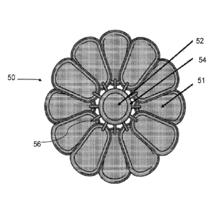
Figs. 7-9 depict an implantable medical device 50 according to one embodiment
of
the present disclosure. As shown, the device 50 comprising a fan-like
configuration with a
plurality of pods 51 distributed about a hub 52 in a concentric and
overlapping manner.
Although the embodiment of Figs. 7-9 depict twelve pods 51 distributed about a
hub, it will
be recognized that the present disclosure is not limited to any particular
number, spacing, or
arrangement of pods 51. In preferred embodiments, the pods 51 are in
communication with
.. a manifold 54 that extends at least partially around the hub 52. The pods
51 are connected
29
CA 03114197 2021-03-24
WO 2020/068852
PCT/US2019/052728
to the hub 52 and manifold 54 via one or more ports 56. The hub, manifold, and
pods are
provided in fluid communication with one another by passageways or conduits
that are
operable to transmit fluid. The passageways or conduits are also operable to
house or
receive mechanical components such as wiring, valves and other features.
Implantable devices of the present disclosure, including that shown in Fig. 7,
are
operable for use as ported immune-isolation devices in patients whom are
insulin dependent,
patients with hemophilia, patients with cancer, patients with chronic pain,
patients with renal
disease, patients requiring drug infusion and shunts, patients with
cardiovascular disease,
patients with electronic implants, and many other long term disease and/or
pain management
applications of the implants.
The fan-like configuration of the implantable device 50 of Fig. 7 comprises
multiple
pods 51 having the structure of the pod 21 of Figs. 4-5, for example, and are
contemplated
as being implanted subcutaneously in a patient. The interior volumes 36 of the
pods 21, 51,
in certain embodiments, are provided with living cells that secrete or that
are induced to
.. secrete therapeutic molecules. These molecules will then diffuse through
the layers of the
device (44a, 42a, 40a of Fig. 6 and 34, 32, 30 of Fig. 5, for example) and
into the host's
surrounding tissue. In this manner, the therapeutic molecule(s) will be taken
up by the
surrounding vasculature and more efficiently distributed throughout the host
body. Methods
of treating patients and administering drug delivery are thus contemplated
wherein the
.. methods comprise providing the implantable devices of the present
disclosure with at least
one of living cells and a therapeutic agent, and thereafter providing the
implantable device
50 within a patient subcutaneously. In further embodiments, the device 50 may
be provided
or replenished with cells or agents subsequent to implantation.
Fig. 10 is a cross-sectional elevation view of a hub 52 and manifold 54. As
shown,
the hub 52 comprises an internal void 60. The hub 52 provides a housing for
various
CA 03114197 2021-03-24
WO 2020/068852
PCT/US2019/052728
elements including, but not limited to a pump, reservoir, oxygen generator,
electronics,
power supply, an injection port, and combinations thereof. The manifold 54
comprises a
pathway to communicate therapeutic agents, nutrients, oxygen, electrical
signals, electrical
power, fluids, gases, and combinations thereof from the hub to one or more
pods 51 (not
shown Fig. 10) via a passage or aperture 62 in the manifold.
In the case of cellular therapies, the pod(s) 21, 51 of an implantable device
of the
present disclosure are provided with cells that secrete therapeutic molecules
intended to treat
a disease condition in the patient. Those cells may be primary, natural cells
obtained from
human donors, an immortalized cell line derived from a specific human tissue,
a human cell
line derived from tissue that does not produce any therapeutic molecule but
has been
genetically engineered in the laboratory to secrete a specific protein or stem
cell derived
tissue in which stem cells have been converted to a specific tissue in the
laboratory.
By way of example, in the case of primary tissue that occurs naturally in the
body,
one might fill the interior volume 36 of a pod with parathyroid tissue
harvested from a
human donor thereby providing parathyroid hormone to individuals suffering
from
parathyroid insufficiency.
In various embodiments, it is contemplated that implants of the present
disclosure
comprise various internal structures and features. For example, and as shown
in Fig. 10, at
least one of the hub 52 and the manifold 54 of the device 50 comprises a pump
80 and an
oxygen sensor 82. Although the pump and the oxygen sensor of Fig. 10 are shown
as being
within the hub 52 and/or manifold 54, it is also contemplated that components
are provided
within pods 21 of the present disclosure. Additionally, devices of the present
disclosure are
not limited to those which comprise pumps and sensors. In addition to or in
lieu of pumps
and sensors, implantable devices of the present disclosure are contemplated as
comprising
electronic components and power storage. For example, in some embodiments,
electronic
31
CA 03114197 2021-03-24
WO 2020/068852
PCT/US2019/052728
components are provided that provide the ability for the implant to
communicate with
additional, external devices. More specifically, it is contemplated that
implantable devices
of the present disclosure comprise Bluetooth, RFID, and/or WiFi enabled
components that
are operable to send and receive signals to a base station or central
computer. Such devices
may communicate information including, for example, a power level of the
device, a fill
level of a therapeutic agent (e.g. insulin), and other information.
Fig. 11 is a cross-sectional view of an implantable device 50 comprising a hub
52
with a manifold 54 and a pod 51 extending therefrom. The device 50 is shown as
being
implanted in the tissue 70 of a patient. In various embodiments, methods are
provided
wherein the device is implanted subcutaneously and preferably at a depth of
less than one
inch within an outer dermis layer of the patient such that the device 50 is
relatively easy to
access for removal, refill, maintenance, etc.
In the case of a cell line, devices of the present disclosure are contemplated
as being
filled with cells maintained in culture at repositories such as the American
Type Culture
Collection that express therapeutic proteins. Fibroblast cell lines may be
used as a generic
cell type for genetic engineering where one or more genes might be inserted by
genetic
engineering methods to create cells that secrete proteins necessary to treat
diseases.
Examples include cells engineered to produce Factor IX for a form of
hemophilia or
erythropoietin for patients with anemia secondary to kidney disease. It is now
possible to
direct the maturation of stem cells along the pathway to specific cell types.
For example,
stem cells can be manipulated in the laboratory to convert to pancreatic cells
such as B-cells
that secrete insulin. Such cells may be loaded into the interior volume 36 of
the pods 21 to
provide a treatment for diabetes.
Figs. 12-14 are detailed cross-sectional views of a portion of an implant 80
according
to one embodiment of the present disclosure. Figs. 12-14 include a scale
indicating the
32
CA 03114197 2021-03-24
WO 2020/068852
PCT/US2019/052728
approximate distance and size of various depicted components. As shown, the
implant
comprises a non-woven mesh structural layer 82. A layer of fibers 86 operable
to permit
vascularization is provided substantially adjacent to the woven mesh 82. In
some
embodiments, the layer of fibers 86 comprises a pore size gradient that
decreases from left
to right in Fig. 12. An immuno-protective layer 88 is provided adjacent to the
layer of fibers
86. In some embodiments, the layer of fibers 86 and the immuno-protective
layer 88
comprise separate layers that are laminated or otherwise adhered together (see
Fig. 1B, for
example). In other embodiments, the layer of fibers 86 and the immuno-
protective layer 88
comprise a single element including, for example, an element formed by
electrospinning or
otherwise depositing PTFE and wherein the immuno-protective layer comprises an
area of
smaller pore sizes than the layer of fibers 86 (see Fig. 1A, for example).
The examples set forth above are provided to give those of ordinary skill in
the art a
complete disclosure and description of how to make and use the embodiments of
the
methods for prediction of the selected modifications that may be made to a
biomolecule of
interest, and are not intended to limit the scope of what the inventors regard
as the scope of
the disclosure. Modifications of the above-described modes for carrying out
the disclosure
can be used by persons of skill in the art, and are intended to be within the
scope of the
following claims.
It is to be understood that the disclosure is not limited to particular
methods or
systems, which can, of course, vary. It is also to be understood that the
terminology used
herein is for the purpose of describing particular embodiments only, and is
not intended to
be limiting.
A number of embodiments of the disclosure have been described. Nevertheless,
it
will be understood that various modifications may be made without departing
from the spirit
33
CA 03114197 2021-03-24
WO 2020/068852 PCT/US2019/052728
and scope of the present disclosure. Accordingly, other embodiments are within
the scope
of the following claims.
34