Note: Descriptions are shown in the official language in which they were submitted.
CA 03114324 2021-03-25
WO 2020/081155 PCT/US2019/049335
1
METHODS OF PROTECTING FURNACE ELECTRODES WITH COOLING LIQUID
THAT CONTAINS AN ADDITIVE
CROSS-REFERENCE TO RELATED APPLICATIONS
[1] This nonprovisional application claims the benefit of U.S. Provisional
Application No. 62/779,457, filed December 13, 2018, and U.S. Provisional
Application
No. 62/745,697, filed October 15, 2018.
FIELD OF DISCLOSURE
[2] This disclosure relates to the implementation of a novel process
whereby the
electrode cooling water in an electric arc furnace (EAF) or ladle metallurgy
furnace (LMF), or
any variation of a furnace that uses water cooled electrodes in the steel
making process is
chemically modified. The modification provides reduced sidewall oxidation of
the electrode
through the formation of a protective barrier on exterior surfaces of the
furnace electrodes,
resulting in extended electrode life.
BACKGROUND
[3] EAF steel producers use electrical energy to melt raw materials to
produce
1 ton to 420 metric tons of steel in vessels. Electrical energy can be
delivered to the furnace as
alternating current (AC) or direct current (DC). The electrical power
delivered to the raw
materials can be as high as 200 MWh in the case of the largest EAF vessels.
This power supply
creates an electrical arc that creates the necessary heat to raise the batch
of steel to temperatures
as high as 1800 C and to allow for further refinement and processing in the
LMF and
subsequent casting and forming operations.
[4] The electrical power is delivered to the steel through graphite
electrodes.
Graphite is the material of choice for electrodes due to the following
characteristics: low
coefficient of thermal expansion (CTE), high tensile strength, high specific
resistance, electrical
resistance that is relatively independent of temperature, and nobility
(cathodic to other materials).
[5] Electrodes are consumables utilized in the electrical steel making
process and
account for a substantial cost for the steel maker. The environment in the
electric arc furnace is
violent and harsh, and causes consumption of electrodes in a range of
approximately 1 kg/metric
ton of steel produced to 2.5 kg/metric ton. Causes of consumption include:
electrical arc at the
electrode tip where localized temperature is approximately 3000 C; electrode
breakage due to
movement of raw materials; thermal shock and subsequent loss of electrode tip;
and oxidation of
the electrode surfaces along the column due to the harsh furnace environment.
Oxidation of the
CA 03114324 2021-03-25
WO 2020/081155 PCT/US2019/049335
2
electrode creates the conical shape of electrodes that are in use and can
account for nearly 50%
of the electrode consumption.
[6] For decades, steel producers and furnace electrode producers have
attempted to
reduce the oxidation rate of the graphite and carbon electrodes through many
different means.
One example is to use electrodes that have surfaces coated with layers formed
from graphite,
metal, aluminum alloys, and pure aluminum. However, these coatings are only
applied once
(e.g., only during the manufacturing of the electrodes), and the coatings are
susceptible to
chemical and physical damage that renders them ineffective. Thus, these type
of coatings can
have short useful life spans.
[7] Changes in the electrode manufacturing process, in electrode coupling
technology, in the recipe for the graphite electrodes, and in operational
procedures like foamy
slag have substantially reduced electrode consumption since 1985 when
electrode consumption
was between 5 to 6 kg/metric ton of steel, to 1 to 2.5 kg/metric ton of steel
in 2018. While this
has been an impressive reduction, market forces have heightened sensitivity to
the consumption
rate. Even incremental decreases in consumption rate have a substantial impact
to the steel
maker.
[8] The oxidation of the electrode is a chemical reaction. The rate of
oxidation of
the electrode increases with increasing temperatures because the reactant
molecules have more
kinetic energy at higher temperatures. The reaction rate (i.e., oxidation
rate) is governed by the
Arrhenius equation which in almost all cases shows an exponential increase in
the rate of
reaction as a function of temperature.
¨Ea
k = ¨
kB T
Where: k = the rate constant
kB = Boltzmann constant
T = absolute temperature
A = a constant for each chemical reaction
Ea = the activation energy
R = the universal gas constant
[9] Therefore, many designs have been developed to cool the bulk of the
electrode
(i.e., lower the temperature of the electrode), but have been abandoned due to
safety concerns.
Applying cooling water to the electrode below the molten steel bath creates a
very dangerous
condition in the case of an electrode break or the failure of the cooling
water channel. The
CA 03114324 2021-03-25
WO 2020/081155 PCT/US2019/049335
3
release of cooling water below the steel bath creates an explosion due to the
rapid expansion as
the water changes phase from water to steam with an approximate volumetric
expansion of
1,100 times. Electrodes used in commercial steel making are currently composed
exclusively of
graphite and do not contain cooling water channels.
[10] To further reduce oxidation of the electrode, spray cooling was
introduced to
the industry and specific designs to cool the electrode using circular spray
headers with multiple
vertical spray headers located at multiple locations around the circumference
of the electrode.
[11] Investigation of water application has been employed to enhance safety
as well
as mitigate oxidation of the electrode. Enhancements, such as providing air to
atomize the water
as it is discharged from the spray nozzle, have been evaluated. Electrode
cooling water flow, in
some facilities, varies depending upon the furnace conditions, providing an
additional level of
safety.
SUMMARY
[12] In contrast to known techniques, and as disclosed herein, the process
of adding
an additive to the spray water system surprisingly can form an effective
protective barrier on a
surface of the electrode to reduce oxidative consumption of the electrode. In
some aspects, this
approach can provide beneficial protection over the electrode length, where
the coating can exist
as a precipitate coating on at least a portion of the exterior surface of the
electrode that is above
the furnace and as molten coating on at least a portion of the exterior
surface of the electrode
that is below the furnace. In other aspects, the presence of the protective
barrier coating can be
maintained by constantly spraying the cooling liquid onto the surface of the
electrode so as to
provide continuous protection against sidewall oxidation, e.g., during a steel
making processes.
In some aspects, this approach can simplify the transportation, packaging, and
handling
processes.
[13] Thus, one objective of the present disclosure is to provide a method
for
chemically modifying the electrode cooling water to reduce the side wall
oxidation of the
furnace electrode, resulting in increased life of the electrode during the
steel making process.
[14] An aspect of the disclosure is a method for forming a protective
barrier on a
furnace electrode, the method including: (i) providing electrode cooling
water, (ii) mixing an
antioxidant additive with the electrode cooling water to form a cooling
liquid, (iii) spraying at
least a surface of the furnace electrode disposed adjacent a furnace with the
cooling liquid,
thereby cooling the furnace electrode, and (iv) forming a protective
antioxidative barrier on the
CA 03114324 2021-03-25
WO 2020/081155 PCT/US2019/049335
4
furnace electrode, the protective antioxidative barrier includes the
antioxidant additive which has
been deposited and/or precipitated on the furnace electrode from the cooling
liquid.
[15] Another aspect of the disclosure is a method for forming a protective
coating on
a furnace electrode that has a surface heated to a temperature of at least 700
C, the method
including: (i) providing a cooling liquid that includes water and an
antioxidant additive; and (ii)
applying the cooling liquid to the surface of the furnace electrode so that
the water evaporates
and the antioxidant additive precipitates and forms the protective coating on
the furnace
electrode.
[16] Another aspect of the disclosure is a method for cooling a furnace
electrode, the
method including: (i) dissolving an antioxidant additive in water to form a
cooling liquid in
which the antioxidant additive is present in an amount of from 100 mg/L to
5,000 mg/L; and (ii)
applying the cooling liquid to a surface of the furnace electrode.
BRIEF DESCRIPTION OF THE DRAWINGS
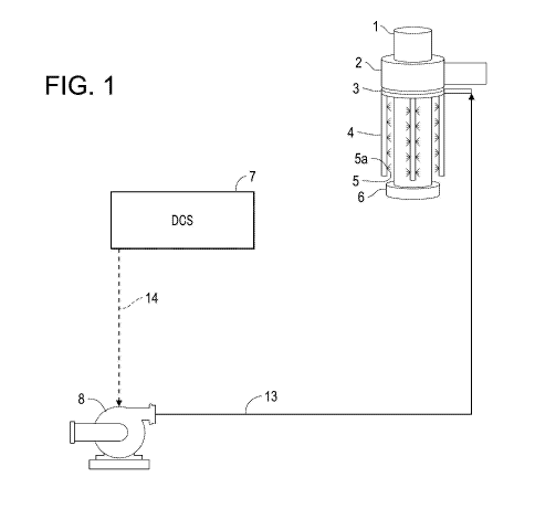
[17] FIG. 1 is a schematic diagram illustrating a spray cooling system for
a single
electrode in a direct current furnace.
[18] FIG. 2 is a schematic diagram illustrating a spray cooling system with
feedback
and control of individual electrode cooling banks for each of the three
electrodes in an
alternating current furnace.
[19] FIG. 3 is a schematic diagram illustrating a spray cooling system with
feedback
and control of individual electrode cooling banks and a chemical metering skid
for the electrodes
in an alternating current furnace.
[20] FIG. 4 is a graph showing the relative electrode consumption by weight
of
produced steel.
[21] FIG. 5 is a graph showing the relative electrode consumption by weight
of
produced steel.
DETAILED DESCRIPTION OF EMBODIMENTS
[22] The disclosed cooling methods may be used to cool any high-temperature
furnace electrodes that are conventionally cooled using water. For example,
the disclosed
cooling methods may be used to cool graphite electrodes in furnaces and/or
steel making
processes such as electric arc furnace, induction furnace, vacuum induction
melting, argon
oxygen decarburization, ladle furnace, vacuum oxygen degassing, vacuum
degassing, vacuum
arc remelting, and electro slag remelting. When the furnace electrode is in
use, a surface of the
CA 03114324 2021-03-25
WO 2020/081155 PCT/US2019/049335
furnace electrode can have a temperature of at least 700 C, at least 1000 C,
at least 1200 C, at
least 1800 C, or at least 3000 C.
[23] As used herein, the term "antioxidant additive" refers to a compound
that can
form a protective antioxidative coating on the surface of the electrodes, and
includes any
precipitating-type chemistry or similar type chemistry that increases the
total dissolved solids of
the spray water, in which the additive in the cooling liquid precipitates or
deposits on a surface
of the electrode to form a protective coating. As used herein, the singular
term "additive" can
refer to either one additive or combinations of two or more additives. Mixing
an antioxidant
additive with water to form a chemically modified cooling liquid can allow the
water to
transport the antioxidant additive to the surface of the electrode where the
heat from the
electrode causes the water to boil off and the additive to precipitate and
deposit on the electrode
surface to form a protective barrier on the electrode surface. Thus, under
this approach, an
additive is added to a cooling liquid so that the additive intentionally
precipitates out of the
solution in a beneficial way, which is contrary to conventional practices
where precipitating
components in industrial cooling systems are considered to be problematic.
[24] In some aspects, the protective barrier that is formed can exist as a
two-phase
coating on an exterior surface of the electrode. Above the furnace, the
coating can exist as a
layer of the precipitates/deposits (typically, as chalky white layer). This
layer is believed to
provide oxidative protection by shielding the graphite surface of the
electrode from atmospheric
oxygen and thus can reduce the rate of side wall oxidation. The
precipitates/deposits layer can
enter the furnace when newer portions of the electrode are moved into the
furnace as the
electrode is consumed during use. Once the precipitates/deposits layer is near
or inside the
furnace, the precipitates/deposits can melt to provide a molten coating on an
exterior surface of
the electrode that is within the furnace. This molten coating is also believed
to shield the surface
of the electrode from oxygen to reduce side wall oxidation. It is believed
that the molten
coating runs down substantially the entire length of the electrode (e.g., at
least 90%) to the
electrode tip to provide oxidative protection along the surface of the
electrode that is within the
furnace. In some aspects, this technique can provide continuous oxidative
protection during
electrode use over substantially the entire electrode length since the
precipitates/deposits layer is
being formed on the electrode above the furnace as the spray cooling water is
applied, and the
molten coating is continuously formed on a portion of the electrode below the
furnace as the
electrode is moved into the furnace.
CA 03114324 2021-03-25
WO 2020/081155 PCT/US2019/049335
6
[25] The melting point of the at least one of the antioxidant additives in
the cooling
water, including one of the primary additives that are added, can be higher
than the temperature
at which rapid oxidation of the electrode material (e.g., graphite) occurs
(e.g., about 700 C). For
example, the melting point of the at least one antioxidant additive can be at
least 710 C, at least
900 C, at least 1,000 C, at least 1200 C, or at least 1,500 C, at least 2,000
C, at least 2400 C,
and up to 3,000 C, or up to 2,800 C. This at least one antioxidant additive
can also be soluble
in water. For example, a solubility of the at least one antioxidant additive
can be at least 10
mg/L, at least 100 mg/L, at least 500 mg/L, or at least 1 g/L. In some
embodiments, the
antioxidant additive can be insoluble in water.
[26] The cooling liquid can be predominantly water, e.g., more than 95 wt%,
more
than 99 wt%, or more than 99.5 wt%. In some embodiments, the cooling liquid
can contain 10-
70 wt%, 15-60 wt%, or 20-50 wt% water, based on a total weight of the cooling
liquid. In some
embodiments, the water can be recycled process water or municipal water.
[27] The concentration of the antioxidant additive in the cooling liquid
can be
present in amounts sufficient to form a protective barrier on the electrode.
Depending on the
diameter of the furnace electrode, a total amount of the antioxidant additive
may be in the range
of from 10 mg/1 to 1,000 mg/1, from 25 mg/1 to 850 mg/1, from 50 mg/1 to 800
mg/1, from
100 mg/1 to 600 mg/1, or from 200 mg/1 to 650 mg/l. In some embodiments, the
amount of
antioxidant additive ranges from 30-90 wt%, 40-85 wt%, or 50-80 wt%, based on
a total weight
of the cooling liquid. In some embodiments, at least 95 wt% of the antioxidant
additive that is
added to the cooling liquid goes into solution, i.e., at the stage where it is
mixed with the cooling
liquid, and in some embodiments all of the antioxidant additive that is added
to the cooling
liquid goes into solution.
[28] The amount of additive that is added to the cooling water can be an
amount that
is sufficient to provide a protective barrier on the furnace electrode.
Generally, more dissolved
solids in the cooling liquid will provide more precipitated solids that are
deposited on the
furnace electrode after the cooling liquid is sprayed onto the electrode.
However, in some
embodiments, the amount and type of additive should not exceed an amount that
would cause
substantial precipitation of the additive in the spray nozzles or the conduits
thereof. In this
regard, the spray nozzles and the associated conduits also operate at
extremely high temperatures,
and the amount and type of antioxidant additive can be selected (e.g., based
on the solubility of
the additive in the cooling liquid) so that the cooling liquid can be sprayed
in the desired
quantities to form a robust protective barrier on the electrode without
scaling or clogging in the
CA 03114324 2021-03-25
WO 2020/081155 PCT/US2019/049335
7
spray nozzles or with minimal scaling/clogging. To further prevent
scaling/clogging, the
additive can include a scale inhibitor or dispersant, and examples of these
are provided below.
[29] In some aspects, a sufficient amount of antioxidant additive is added
to the
cooling liquid to form a protective barrier coating on a surface of the
electrode when the cooling
liquid is applied to the electrode. Above the furnace, the protective barrier
coating can have a
thickness ranging from 0.005 to 1 mm, 0.01 to 0.7 mm, or from 0.05 to 0.3 mm.
In some
embodiments, the thickness of the protective barrier is not more than 5 mm, or
2 mm. The
cooling water can be sprayed so that the protective barrier coating has a
substantially uniform
structure on an exterior surface of the electrode that is above the furnace,
i.e., so that there are no
patches where the electrode is exposed and so the coating thickness is
substantially constant
across the surface (e.g., deviating by no more than 20 % from an average
thickness). Above the
furnace, the protective barrier coating typically has a white, chalky or
frosted appearance. This
coating can be formed to have sufficient structural integrity and cohesiveness
to withstand the
harsh environment during electrode use, including high temperatures and
mechanical vibrations.
In this regard, the coating can form a tenacious protective barrier that does
not flake or otherwise
come off of the electrode surface during use. As described above, it is
believed that at least
some of the precipitated/deposited antioxidant additive becomes molten inside
the furnace,
which forms a molten coating that flows downward along the exterior surface of
the electrode
toward the tip of the electrode.
[30] The method provided herein can use any suitable antioxidant additive
and is not
inherently limited to any specific chemistries. In this regard, it is believed
that the protective
barrier coating can be provided by sufficient dissolved solids in the cooling
water. Exemplary
antioxidant additives suitable for use in the present method include fluorides
(e.g., alkali metal
fluorides; alkaline earth metal fluorides, such as calcium fluoride and
magnesium fluoride;
transition metal fluorides; post-transition metal fluorides; ammonium
fluorides; and sodium
aluminum fluoride), chlorides (e.g., alkali metal chlorides; alkaline earth
metal chlorides, such
as calcium chloride and magnesium fluoride; transition metal chlorides; post-
transition metal
chlorides; and ammonium chlorides), bromides (e.g., alkali metal bromides;
alkaline earth metal
bromides, such as calcium bromide and magnesium bromide; transition metal
bromides; post-
transition metal bromides; and ammonium bromides), nitrates (e.g., alkali
metal nitrates;
alkaline earth metal nitrates, such as calcium nitrate and magnesium nitrate;
transition metal
nitrates; post-transition metal nitrates; and ammonium nitrates), sulfates
(e.g., alkali metal
sulfates; alkaline earth metal sulfates, such as calcium sulfate and magnesium
sulfate; transition
CA 03114324 2021-03-25
WO 2020/081155 PCT/US2019/049335
8
metal sulfates; post-transition metal sulfates; and ammonium sulfates),
silicates (e.g., alkali
metal silicates), phosphates or orthophosphates (e.g., alkali metal salts or
alkaline earth metal
salts, such as calcium or magnesium salts, or transition metal salts or post-
transition metal salts
or ammonium salts of orthophosphoric acid, aluminum orthophosphate), phosphate
derivatives
or polyphosphates (e.g., alkali metal salts or alkaline earth metal salts,
such as calcium or
magnesium salts, or transition metal salts or post-transition metal salts or
ammonium salts of
pyrophosphoric acid, tripolyphosphoric acid, tetrapolyphosphoric acid, and
trimetaphosphoric
acid, and alkali metal hexametaphosphate), alkali metal salts or alkaline
earth metal salts of
boric oxide, metaboric acid, or boric acid (e.g., sodium borate), sodium
borofluoride, and
combinations thereof. In some embodiments, the antioxidant additive is an
alkali metal
hexametaphosphate (e.g., sodium hexametaphosphate), an alkaline earth metal
hexametaphosphate, a transition metal hexametaphosphate, ammonium
hexametaphosphate, an
alkali metal salt of pyrophosphoric acid (e.g., tetrasodium pyrophosphate), an
alkaline earth
metal salt of pyrophosphoric acid (e.g., a calcium salt of pyrophosphoric
acid, a magnesium salt
of pyrophosphoric acid), a transition metal salt of pyrophosphoric acid, an
ammonium salt of
pyrophosphoric acid, or combinations thereof.
[31] As used herein, the term "alkali metal" refers to lithium, sodium,
potassium,
rubidium, and cesium. The term "alkaline earth metal" refers to beryllium,
magnesium, calcium,
strontium, and barium. The term "transition metal" refers to scandium,
titanium, vanadium,
chromium, manganese, iron, cobalt, nickel, copper, yttrium, zirconium,
niobium, molybdenum,
ruthenium, rhodium, palladium, silver, hafnium, tantalum, tungsten, rhenium,
osmium, iridium,
platinum, and gold. The term "post-transition metal" refers to aluminum,
indium, gallium, tin,
bismuth, lead, thallium, zinc, cadmium, and mercury.
[32] The term "ammonium" refers to a cation formed from an amine and a
hydrogen
ion. Exemplary amines include ammonia, a primary amine represented by formula
NH2R, a
secondary amine represented by NHR2, and a tertiary amine represented by
formula NR3, where
each R is independently an optionally substituted alkyl, an optionally
substituted aryl, and an
optionally substituted arylalkyl. The term "alkyl", as used herein, refers to
a straight, branched,
or cyclic hydrocarbon fragment. Non-limiting examples of such hydrocarbon
fragments include
methyl, ethyl, propyl, isopropyl, butyl, isobutyl, t-butyl, pentyl, isopentyl,
neopentyl, hexyl,
isohexyl, 3-methylpentyl, 2,2-dimethylbutyl, and 2,3-dimethylbutyl. As used
herein, the term
"cyclic hydrocarbon" refers to a cyclized alkyl group. Exemplary cyclic
hydrocarbon (i.e.
cycloalkyl) groups include, but are not limited to, cyclopropyl, cyclobutyl,
cyclopentyl,
CA 03114324 2021-03-25
WO 2020/081155 PCT/US2019/049335
9
cyclohexyl, norbornyl, and adamantyl. Branched cycloalkyl groups, such as
exemplary 1-
methylcyclopropyl and 2-methycyclopropyl groups, are included in the
definition of cycloalkyl
as used in the present disclosure. The term "aryl," as used herein, and unless
otherwise specified,
refers to a substituent that is derived from an aromatic hydrocarbon (arene)
that has had a
hydrogen atom removed from a ring carbon atom. Aryl includes phenyl, biphenyl,
naphthyl,
anthracenyl, and the like. The term "arylalkyl" as used in this disclosure
refers to a straight or
branched chain C1 to C8 alkyl moiety that is substituted by an aryl group or a
substituted aryl
group having 6 to 12 carbon atoms. "Arylalkyl" includes benzyl, 2-phenethyl, 2-
methylbenzyl,
3-methylbenzyl, 4-methylbenzyl, 2,4-dimethylbenzyl, 2-(4-ethylphenyl)ethyl, 3-
(3-
propylphenyl)propyl.
[33] In some embodiments, the cooling liquid contains a mixture of an
alkali metal
hexametaphosphate and an alkali metal salt of pyrophosphoric acid. A ratio of
the weight of
alkali metal hexametaphosphate to the weight of the alkali metal salt of
pyrophosphoric present
in the cooling liquid is in a range of from 1:100 to 100:1, from 1:50 to 50:1,
or from 1:10 to 10:1.
[34] In some embodiments, a mixture of a salt of hexametaphosphate and a
salt of
pyrophosphoric acid is added to the cooling water. The cations of these salts
can be exchanged
with the alkali metal cations or alkaline earth metal cations (e.g., calcium)
initially present in the
cooling water to form in situ alkali metal salts (or alkaline earth metal
salts) of
hexametaphosphate and pyrophosphoric acid. In some embodiments, when an alkali
metal
hexametaphosphate (e.g., sodium hexametaphosphate) is added to the cooling
water, the alkali
metal cation can be exchanged with the alkaline earth metal cations (e.g.,
calcium) initially
present in the cooling water to form in situ alkaline earth metal phosphate
(e.g., calcium
phosphate), alkaline earth metal phosphonate, and/or alkaline earth metal
trimetaphosphate,
which in turn are sprayed onto the furnace electrode to form the protective
barrier. In some
embodiments, alkaline earth metal cations (e.g., in the form of calcium, such
as calcium
chloride) are deliberately added to the cooling water to facilitate the
formation of the protective
barrier.
[35] The specific additive(s) can be selected depending on the initial
water
chemistry of the spray water that is used to cool the electrode and the final
water chemistry of
the spray water (i.e., after the additive is added). This selection can depend
on several factors
that are specific to the particular furnace, including the ability to form a
molten coating in the
furnace while the electrode is in use. In some embodiments, specific compounds
may be
considered to be particularly useful additives for forming the protective
coating, such as one or
CA 03114324 2021-03-25
WO 2020/081155 PCT/US2019/049335
more of phosphates, phosphonates, calcium salts, magnesium salts, molybdates,
borates, and
silicates. In some embodiments, including Examples 2-4 below, the cooling
water can contain
(i) one or more additive selected from phosphates, phosphonates, calcium
salts, magnesium salts,
molybdates, boron salts, and silicates, and (ii) one or more additive selected
from a scale
inhibitor and a dispersant.
[36] In some embodiments, the additive can be selected so that the cooling
liquid
can have a hardness of at least 0.5 mmol/L, at least 1.0 mmol/L, at least 1.5
mmol/L, or at least 3
mmol/L. In some embodiments, the hardness is not more than 4 mmol/L, not more
than 2
mmol/L, or not more than 1.2 mmol/L. As used herein, the term "hardness"
refers to the sum of
the molar concentrations of calcium and magnesium ions in the cooling liquid.
It is believed that
using a cooling liquid having a higher hardness can improve the formation of
the protective
barrier by, for example, increasing the speed of formation of the protective
barrier.
[37] The additive can also include a scale inhibitor to prevent scaling in
the nozzle
or conduits, such as scale inhibitors and dispersants selected from the group
consisting one or
more of unsaturated carboxylic acid polymers such as polyacrylic acid, homo or
co-polymaleic
acid (synthesized from solvent and aqueous routes); acrylate / 2-acrylamido-2-
methylpropane
sulfonic acid (APMS) copolymers, acrylate/acrylamide copolymers, acrylate
homopolymers,
terpolymers of carboxylate/sulfonate/maleate, terpolymers of acrylic
acid/AMPS; phosphonates
and phosphinates such as 2-phosphonobutane-1,2,4-tricarboxylic acid (PBTC), 1-
hydroxy
ethylidene-1,1-diphosphonic acid (HEDP), amino tris methylene phosphonic acid
(ATMP), 2-
hydroxyphosphonocarboxylic acid (HPA), and combinations thereof.
[38] Industrial application of this method indicates that an additional 2
to 40 percent,
2 to 30 percent, 5 to 20 percent, or 3 to 15 percent electrode consumption is
avoided through the
implementation of this method. For example, the protective coating can reduce
oxidative
electrode consumption by 2 to 30 percent as compared to a like method in which
only water
cools the furnace electrode. As would be appreciated in the art, a reduction
in oxidative
electrode consumption of even 2 percent is considered to be significant and
can provide for
substantial savings. Electrode consumption is typically determined over a
period of time. For
example, in one embodiment, the electrode consumption is calculated as the
consumption over
one week period. In other embodiments, the consumption may be calculated over
a two week
period. In still other embodiments, the electrode consumption is calculated
over a one month
period. In still further embodiments, the consumption is calculated for
periods longer than about
3 days. In some embodiments, the consumption is calculated weekly or monthly.
Electrode
CA 03114324 2021-03-25
WO 2020/081155 PCT/US2019/049335
11
consumption can be determined by methods known to one skilled in the art, for
example, by
measuring the value of the eddy current in the electrode, which can be
correlated to the
consumption rate. See U.S. Patent No. 4,048,556 to Roach et al., which is
incorporated herein by
reference in its entirety. In some embodiments, actual electrode consumption
can be measured in
the process of replacing the furnace electrodes per ton of produced steel. For
example, the
number of heats of a known mass of steel produced by the furnace (e.g., the
EAF or LMF) per
electrode can be measured. As an another example, electrode consumption can be
measured by
removing the electrode, weighing the electrode, and repeating this process for
other electrodes
that are used within a specified time period.
[39] FIG. 1 illustrates an example of a spray cooling arrangement for a
direct current
furnace. The electrode holder 2 holds the graphite electrode 1 which extends
into the furnace
through the top of the furnace 6. The size of the graphite electrode 1 can
typically vary from
75 mm to 700 mm in diameter, although electrodes of up to 800 mm are
available. The
antioxidant additive and water can be pre-mixed offline to form a cooling
liquid which is
supplied to the flow path 13 via the pump 8 (e.g., a booster pump).
[40] The spray cooling system (i.e., the cooling bank) has a circular ring
distribution
header 3 and a vertical spray distribution header 4. The vertical spray
distribution header 4
includes a plurality of nozzles 5a from which the cooling liquid 5 is sprayed
onto the outer
circumference of the electrode 1. In this manner, the cooling of the electrode
occurs from the
electrode holder 2 to the top of the furnace 6. At the point of impingement,
or where the water
meets the electrode surface, the temperature of the cooling liquid can be
below the boiling point
of the liquid. If cooling liquid enters the furnace during operation, it would
evaporate prior to
reaching the molten metal bath and avoid explosion. The cooling liquid may
also provide
protection for various components of the cooling water system in fluid
communication with the
electrode cooling water. These components include, the spray nozzles, and
components on flow
path 13 (e.g., control valves, flow meters, and pumps).
[41] In most embodiments, the cooling liquid is constantly applied to the
electrodes.
The application of cooling liquid can be generally held to below 4.5 m3/h for
a 600-mm diameter
electrode. Flow rates for smaller and larger electrodes can be varied based
upon the surface
coverage area. Depending on the application, the flow rate may vary from 0.25
m3/h to 10 m3/h,
from 1 m3/h to 5 m3/h, or from 2 m3/h to 4 m3/h, for each electrode (i.e.,
phase). The cooling
liquid can be sprayed in a direction orthogonal to the longitudinal axis of
the graphite electrode
1, or at a downward or upward angle, e.g., of from 100 to 35 with respect to
the horizontal. The
CA 03114324 2021-03-25
WO 2020/081155 PCT/US2019/049335
12
cooling liquid can be sprayed with a jet pressure of from 0.5 to 3 kg/cm2 and
at a rate of from
0.8 to 6.0 1/minute, or up to 75 1/minute (about 20 gallons/minute), for each
electrode. A
sufficient amount of cooling liquid is sprayed at the electrode to keep the
electrode cooled. In
this process, a sufficient amount of the cooling liquid is applied to the
surface of the furnace
electrode so that the protective coating is formed to reduce the oxidative
electrode consumption,
as compared to a like method in which only water cools the furnace electrode.
[42] When the spray of cooling liquid 5 contacts the hot surface of the
graphite
electrode 1, the cooling liquid evaporates to produce a cooling effect on at
least the portion of
the electrode 1 above the furnace and to deposit the antioxidant additive,
e.g., when the additive
dissolved solids precipitates out of the cooling liquid. For example, as the
cooling liquid flows
down the exterior surface of the electrode, the water evaporates, thereby
concentrating the
antioxidant additive in the remaining cooling liquid. When the concentration
of the antioxidant
additive in the remaining cooling liquid reaches a saturation point, the
excess antioxidant
additive will precipitate/deposit on the electrode surface to form a
protective barrier. The
protective barrier made up of the antioxidant additive would also form when
the remaining water
in the cooling liquid is driven off.
[43] In some embodiments, the electrode 1 can be cooled uniformly over its
entire
length above the furnace. As the cooling liquid is sprayed onto the portion of
the electrode 1
above the furnace, this portion may be covered uniformly by the
precipitates/deposits protective
barrier. As the production of steel progresses, the electrode below the
furnace can be consumed
by processes, such as tip sublimation, sidewall oxidation, and/or losses due
to various forms of
breakage, butt losses, and spalling. To account for these losses, the
electrode can be moved or
pushed into furnace so as to introduce portions of the electrode that was
previously above the
furnace into the furnace. The precipitates/deposits coating can then melt as
it moves toward the
interior of the furnace to form a molten protective coating on at least a
portion of the electrode
below the furnace.
[44] FIG. 2 illustrates an example of the spray cooling arrangement for an
alternating current furnace. There are three electrodes in the alternating
current furnace, and
each of the electrodes supply one of the electrical phases.
[45] Similar to FIG. 1, FIG. 2 includes a flow path 13 that allows the
cooling liquid
to flow to the spray cooling system. A control valve 9 regulates the flow for
spray cooling to an
individual electrode, based upon feedback 17 from a distributed control system
(DCS) 7. An in-
line flow meter 10 measures the flow rate of cooling liquid and then sends a
feedback 16 to the
CA 03114324 2021-03-25
WO 2020/081155 PCT/US2019/049335
13
DCS 7 that actuates a pump 8 (e.g., a booster pump) to supply cooling liquid,
which is pre-
mixed offline. For example, the DCS 7 sends a feedback 14 to the pump 8 to
supply the cooling
liquid. The parameters (e.g., electrode and spray parameters) for this spray
cooling arrangement
can be the same or substantially the same as those described for FIG. 1.
[46] FIG. 3 illustrates an example of the spray cooling arrangement for an
alternating current furnace. In this embodiment, the spray cooling arrangement
includes a
chemical metering skid 11 to supply the antioxidant additive in-line. The in-
line flow meter 10
measures the flow rate of cooling liquid and then sends a feedback 16 to the
DCS 7 that
actuates: (i) a pump 8 (e.g., a booster pump) to supply cooling water, and
(ii) a chemical
metering skid 11 to supply the antioxidant additive. For example, the DCS 7
can send a
feedback 14 to the pump 8 to supply the cooling water, as described above in
connection with
FIG. 2. The DCS 7 can also perform the calculations and send a digital or an
analogue feedback
15 to the chemical metering skid to supply the antioxidant additive at an
accurate and discrete
dosage. The dosage and the timing between each dosage may be empirically
determined. For
example, the dosage and timing may depend on the furnace type, furnace
operation, and the
condition of the steel bath. The antioxidant additive can be supplied from the
chemical metering
skid 11 in a neat form (if liquid) or as a concentrated solution. The
antioxidant additive can be
introduced to (e.g., injected into) the flow path 13 at location 12,
downstream of the pump 8.
Supplying the antioxidant additive at location 12 can allow the mixing of the
antioxidant
additive with the water to form the cooling liquid. In some embodiments, the
antioxidant
additive is introduced to the flow path 13 at a location upstream of the pump
8. The parameters
(e.g., electrode and spray parameters) for this spray cooling arrangement can
be the same or
substantially the same as those described for FIGS. 1 and 2.
[47] Accordingly, the consumption of the electrodes can be reduced through
the
application of an antioxidant additive in the electrode spray cooling liquid.
The presence of the
antioxidant additive in the electrode spray cooling water allows for the
formation of protective
barrier at the same time the electrode is being cooled, and thus can be an
efficient and effective
method for reducing the oxidation of the electrode.
[48] Utilization of surfactants as an additive may enhance the performance
of the
cooling liquid and thus may further reduce the consumption rate of electrode.
In some
embodiments, the cooling liquid further comprises a surfactant or a blend of
surfactants of the
amount and type described in the U.S. Provisional Application No. 62/745,729,
titled "Spray
Cooling Furnace Electrodes With A Cooling Liquid That Contains Surfactants,"
filed on
CA 03114324 2021-03-25
WO 2020/081155 PCT/US2019/049335
14
October 15, 2018, the entirety of which is hereby incorporated by reference
herein. The cooling
water may include other additives such as biocides, detergents, wetting
agents, and the like.
EXAMPLE 1
[49] A cooling liquid containing water, sodium hexametaphosphate, and
tetrasodium
pyrophosphate was sprayed onto hot ultra-high-power (UHP) electrodes. Each
electrode had a
diameter of 400 mm. The cooling liquid contained a total antioxidant additive
amount of
500 mg/l. The spray rate of the cooling liquid was dynamic and was based upon
furnace
conditions in operation. The spray rate ranged between 3 gallons and 20
gallons per minute per
electrode during the heating of the electrode. Electrode consumption was
reduced from about
2.3-2.5 lb/ton (see Comparative Example 1) to 1.8-2.0 lb/ton over a two-week
evaluation period.
EXAMPLE 2
[50] This example tested the effect of a first and second additive on the
oxidative
consumption of an electrode at a steel manufacturing site. This site is a
three phase EAF
production facility, which experiences an average electrode consumption rate
of about 2-3 lb/ton.
The dosage of the first additive was first varied and then kept constant. When
the dosage of the
first additive was increased, increasing levels of electrode protection were
confirmed, and the
sidewall oxidation of the electrode decreased. However, the maximum dosage of
the first
additive was limited by the tendency of the cooling liquid to scale. (Similar
observations
regarding the dosages and the levels of sidewall oxidation were also observed
in Examples 3 and
4 below.) Inspections of the spray ring and nozzles were regularly made to
ensure proper water
flow and spray pattern (to the electrodes) were obtained during the entire
campaign.
[51] When the dosage of the first additive was held constant, the second
additive
was added to further study the impact on electrode consumption rates. At the
end of the trial
period, a thorough study of the plant operating data was conducted, and a
reduction in electrode
consumption between 3% to 9% was observed. The specific reduction depended on
the steel
melting practices that were used (i.e., operation conditions). The reduction
in electrode
consumption over time is shown in Fig. 4. The bold vertical line in Fig. 4
indicates the start of
the trial period.
EXAMPLE 3
[52] This example tested the effect of a third additive composition on the
oxidative
consumption of an electrode at another steel manufacturing site. This site is
a three phase EAF
production facility, which experiences high electrode costs and an average
electrode
consumption rate of about 5-7 lb/ton. The study of the third additive was
based on spray water
CA 03114324 2021-03-25
WO 2020/081155 PCT/US2019/049335
chemistry and operational conditions of the plant. Various dosages of the
third additive were
studied during the trial with final dosage targets based on operational
changes managed by the
hosting plant. A constant dosage of the third additive was also studied. The
test showed an
electrode consumption reduction between 5% to 12% over a 90-day test period,
and further
improvements are believed to be manageable. The reduction in electrode
consumption is shown
in Fig. 5. The bold vertical line in Fig. 5 indicates the start of the trial
period.
EXAMPLE 4
[53] This example tested the effect of a fourth additive composition on the
oxidative
consumption of an electrode at another North American steel manufacturing
site. This site is a
three phase EAF production facility, which experiences initial high electrode
costs and
consumption rates. The study of the fourth additive was selected based on the
plant spray water
chemistry and various operating constraints of the plant. The dosage of the
fourth additive was
varied throughout a 90-day trial as different operating conditions were
evaluated. It was found
that during the trial period the consumption of the electrodes were reduced,
on average, by 6%.
COMPARATIVE EXAMPLE 1
[54] A cooling liquid containing water only was sprayed onto hot ultra-high-
power
(UHP) electrodes. Each electrode had a diameter of 400 mm. The spray rate of
the cooling liquid
was dynamic and was based upon furnace conditions in operation. The spray rate
ranged
between 3 gallons and 20 gallons per minute per electrode during the heating
of the electrode.
The electrode consumption rate was determined to be 2.3-2.5 lb/ton over a two-
week evaluation
period.
[55] It will be apparent to those skilled in the art that variations of the
process
described herein are possible and are intended to be encompassed within the
scope of the present
invention.