Note: Descriptions are shown in the official language in which they were submitted.
HEAD WEARABLE DEVICES AND METHODS
CROSS-REFERENCE TO RELATED APPLICATIONS
[0001] This
application claims the benefit of and priority to both U.S.
Provisional Patent Application Serial Number 62/741,385, filed on October 4,
2018, and U.S. Provisional Patent Application Serial Number 62/741,636,
filed on October 5, 2018.
TECHNICAL FIELD
[0002] The present
disclosure relates generally to devices to be
adjustably worn on a human head to provide supplemental light for surgical
and medical procedures. Specifically, the present disclosure relates to light
emitting diode ("LED") based surgical headlight systems.
BACKGROUND
[0003] Existing
surgical headlights require a significant amount of light to
provide sufficient illumination for the surgeon during a typical case.
Surgical
headlights are also preferably lightweight so that neck and head fatigue of
the surgeon is minimized. LEDs are semiconductor devices that emit light by
application of electrical power (watts). LEDs are a feasible light source for
a
surgical headlight luminaire. However, the problem is that LEDs generate
heat. One of the major challenges LEDs pose in many applications is
removing the heat from the LED. Excess heat must be removed so that the
semiconductor junction temperature does not exceed recommended
maximum temperature. In addition, as the junction temperature of the LED
rises, the efficiency also drops. LED light output is limited by its maximum
heat junction temperature, so to increase light output without damaging the
LED or reducing its operating efficiency, heat must be transferred quickly
and efficiently.
1
Date Recue/Date Received 2023-09-20
CA 03114516 2021-03-26
WO 2020/072088 PCT/US2018/067231
[00041 There remains a
need for LED surgical headlights which allow
efficient transfer of heat energy from the LED so that the LED is sufficiently
cooled and retains its light output performance and reliability.
[00051 Furthermore, surgical headlights are worn by healthcare
professionals to provide illumination to aid visualization during surgical,
diagnostic, or therapeutic procedures. Headlight devices typically include a
headband, a luminaire, and other components and accessories, which could
cause discomfort or neck and head fatigue in the wearer, particularly when
worn in a long procedure.
Thus, there remains a need for surgical headlight
devices and systems that provide enhanced comfort when worn by a wearer
(e.g., a surgeon) for an extended period of time.
SUMMARY
[00061 It is an object of
the present disclosure to provide a head wearable
device comprising a headpiece; a housing on a top surface of the
headpiece; a luminaire attached to the headpiece, the luminaire comprising
a luminaire housing and at least one light source thermally connected to a
heatsink, the at least one light source and the heatsink being located within
the luminaire housing; a duct system connected between the luminaire and
the housing; a ball joint rotatably connecting the duct system to the
luminaire; an air moving device located configured to induce a cooling air
flow through an inlet formed in the luminaire housing, through the heatsink,
through the ball joint, through the duct system, and out of an exhaust formed
in the housing on the top
surface of the headpiece; and a controller
configured to monitor a temperature of the at least one light source and to
modulate an operational setting of the air moving device to maintain the
temperature of the at least one light source within a predetermined operating
range.
[00071 It is a further
object of the present disclosure to provide a head
wearable device comprising: a headpiece comprising a headband
comprising a top strap and at least two lateral straps; and an occipital
basket
2
CA 03114516 2021-03-26
WO 2020/072088
PCT/US2018/067231
comprising a strap, the occipital basket being attached to the headband by
at least one lateral extension strap pivotably attached by a hinge to a distal
end of each respective lateral strap of the headband; a first housing attached
to an outer surface of the top strap of the headband; a depth adjuster
attached to the first housing, the depth adjuster comprising a first gear
rotatably fixed to a first knob; herein the strap of the occipital basket
comprises a slot with a plurality of teeth formed around a longitudinal edge
of
the slot; wherein the first gear is captively held within the slot and engages
with the plurality of teeth; wherein a rotary movement of the first gear
causes
a longitudinal movement of the strap of the occipital basket to change a
distance between the occipital basket and the first housing; wherein a depth
of the headpiece changes when the distance between the occipital basket
and the first housing changes, or increases or decreases; and wherein the
strap comprises a first visual index comprising a first plurality of
sequential
characters, each of which correspond to one of a plurality of predetermined
depth settings of the headpiece; and a second housing attached to an outer
surface of the occipital basket; a circumferential adjuster at an outer
surface
of the occipital basket, the circumferential adjuster comprising a second gear
rotatably fixed to a second knob; wherein the lateral extension straps each
comprise a slot with a plurality of teeth formed around a longitudinal edge of
the slot; wherein the second gear is captively held within the slot of each
lateral extension strap and engages with the plurality of teeth of each of the
lateral extension straps; wherein a rotary movement of the second gear
causes a longitudinal movement of the lateral extension straps to change a
circumference of the headpiece; and wherein at least one of the lateral
extension straps comprises a second visual index comprising a second
plurality of sequential characters, each of which correspond to one of a
plurality of predetermined circumferential settings of the headpiece; wherein
the lateral extension straps rotate about the hinge, relative to the lateral
straps as the depth of the headpiece changes.
[0008] Still
another object of the present disclosure is to provide a method
of adjusting a size of a headpiece of a head wearable device to a head size
3
CA 03114516 2021-03-26
WO 2020/072088 PCT/US2018/067231
of a wearer, the headpiece comprising a headband and an occipital basket.
The method comprises attaching a first housing to an external surface of a
top strap of the headband; inserting a strap of the occipital basket at least
partially into the first housing; engaging a first gear with a plurality of
teeth
formed in a slot, which is longitudinally oriented along a length of the strap
of
the occipital basket; turning a first knob, which is rotationally locked to
the
first gear, to adjust a depth of the headpiece; attaching a second housing to
an external surface of the occipital basket; inserting an end of at least two
lateral extension straps into the second housing, with the end of a first
lateral
extension strap being inserted from an opposite end of the housing from the
end of a second lateral extension strap, wherein the two lateral extension
straps are hingedly attached to lateral straps of the headband to define a
circumference of the headpiece; engaging a second gear with a plurality of
teeth formed in a slot of each of the lateral extension straps such that the
second gear is engaged with both of the lateral extension straps; and turning
a second knob, which is rotationally locked to the second gear, to adjust a
circumference of the headpiece.
[0009] In another object
of the present disclosure, headlight devices with
a padding system are provided. Such headlight devices comprise a
headband having a rear portion, two side portions, and a top portion, each of
which have a respective inner surface; a padding system comprising a rear
pad, which is attached to the inner surface of the rear portion of the
headband; a side pad attached to the inner surfaces of the two side portions
of the headband; a top pad attached to the inner surface of the top portion of
the headband; and, optionally, a brow pad attached to the inner surface of
the headband at an intersection of the top portion and the two side portions;
wherein at least one of the rear pad and the brow pad comprises a first layer
of a first cushioning material having a first durometer, and a second layer of
a second cushioning material having a second durometer that is harder than
the first durometer.
4
CA 03114516 2021-03-26
WO 2020/072088
PCT/US2018/067231
[0010j
According to some embodiments of the present subject matter, the
first cushioning material is silicone foam having a first durometer, and the
second cushioning material is silicone foam having a second durometer that
is harder than the first durometer; the second layer of the second cushioning
material is closer than the first layer of the first cushioning material to
the
inner surface of the headband.
[0011]
According to further embodiments of the present subject matter,
the first layer of the first cushioning material and the second layer of the
second cushioning material are each perforated; the majority of the
perforations in the first layer of the first cushioning material may be
generally
circular, and the majority of the perforations in the second layer of the
second cushioning material may be in a shape other than circular. For
example, the perforations in the second layer of the second cushioning
material are generally square or rectangular, or generally in a grid-like
pattern.
[0012] In an
aspect of the present disclosure, the second layer of the
second cushioning material has more open space on its upper or lower
surface due to perforations than the first layer of the first cushioning
material.
In another aspect of the present disclosure, the total volume of cavity due to
perforations in the second layer of the second cushioning material is higher
than the total volume of cavity in the first layer of the first cushioning
material.
[0013] In
additional embodiments of the present subject matter, the rear
pad has an inner surface in contact with a wearer and an outer surface
attached to the inner surface of the rear portion of the headband, and the
rear pad comprises a recess on its inner surface; at least one of the top pad
and the side pad may comprises urethane foam and forms segments.
[0014] It is
another object of the present disclosure to provide a headlight
device comprising a headband for encircling the head of a wearer; a padding
5
CA 03114516 2021-03-26
WO 2020/072088 PCT/US2018/067231
system comprising a pad removably attached to at least a portion of the
headband; wherein the pad comprises a first layer of a first cushioning
material having a first durometer, and a second layer of a second cushioning
material having a second durometer that is harder than the first durometer;
and wherein the first layer is perforated in a first perforation pattern, and
the
second layer is perforated in a second perforation pattern that differs from
the first perforation pattern.
[0015] In some
embodiments, the perforations in the first layer are
generally in a first perforation shape and the perforations in the second
layer
are generally in a second perforation shape that differs from the first
perforation shape. The perforation patterns can be chosen taking into
consideration the softness and density of each layer specific to the
cushioning material used. Punching holes or otherwise creating perforation
or cavity in the cushioning material reduces the weight of the padding and
thus the stress on the wearer, but the removal of cushioning material may
reduce the support that the layer can provide. The perforations in the layers
of cushioning material also improve heat dissipation and air-flow. Perforation
patterns are selected to achieve a desired level of support and comfort.
[0016] According to some
embodiments of the present subject matter, a
headlight device is provided, the headlight device comprising: a headband
for encircling the head of a wearer; a padding system comprising a rear pad
removably attached to at least a portion of the headband; wherein the rear
pad comprises a first layer of a first cushioning material having a first
durometer, and a second layer of a second cushioning material having a
second durometer that is different from the first durometer; wherein the first
layer is perforated in a first perforation pattern, and the second layer is
perforated in a second perforation pattern that differs from the first
perforation pattern; wherein the first layer comprises an inner surface in
contact with a wearer; wherein the second layer comprises an outer surface
attached to the inner surface of the rear portion of the headband; and
wherein the rear pad comprises a recess on an inner surface thereof.
6
CA 03114516 2021-03-26
WO 2020/072088 PCT/US2018/067231
[0017] Although the
embodiments of headlight devices are shown herein,
the features of the padding systems disclosed herein can be applied to other
head wearable devices. Other features and advantages of the present
subject matter will become more apparent from the following detailed
description of the subject matter, when taken in conjunction with the
accompanying example drawings.
BRIEF DESCRIPTION OF THE DRAWINGS
[0018] A full and
enabling disclosure of the present subject matter is set
forth more in the remainder of the specification, including reference to the
accompanying, example figures, in which:
[0019] FIGS. 1-7 are
respective directional perspective views of an
embodiment of the head wearable device, in accordance with the disclosure
herein;
[0020] FIGS. 8 and 9A are
partial exploded views of the head wearable
device of FIGS. 1-7, in accordance with the disclosure herein;
[0021] FIG. 9B is a
partial rear assembly view of the front headstrap of
the head wearable device of FIGS. 1-7, in accordance with the disclosure
herein;
[0022] FIGS. 10-12 show
various aspects of the thermal management
features of the head wearable device of FIGS. 1-7, in accordance with the
disclosure herein;
[0023] FIGS. 13-15 show
internal views of one of the adjustment devices
of the head wearable device of FIGS. 1-7, in accordance with the disclosure
herein;
7
CA 03114516 2021-03-26
WO 2020/072088
PCT/US2018/067231
[0024] FIG.
16 is a view of the head wearable device of FIGS. 1-7
showing the padding arranged therein, in accordance with the disclosure
herein;
[0025] FIG. 17 is an
assembly view of the head wearable device of FIGS.
1-7 with the padding omitted, in accordance with the disclosure herein;
[0026] FIGS.
18 and 19 are partial exploded views to show the
adjustment features of the head wearable device of FIGS. 1-7, in
accordance with the disclosure herein;
[0027] FIG.
20 is an exterior view of a rear pad of the padding system
shown in the head wearable device of FIGS. 1-7, in accordance with the
disclosure herein;
[0028] FIG.
21 is a side view of an example embodiment of the
cushioning materials in the rear pad of FIG. 20, in accordance with the
disclosure herein;
[0029] FIG. 22 is a
plan view of an example embodiment of the first layer
of the first cushioning material in the rear pad shown in FIGS. 20 and 21, in
accordance with the disclosure herein;
[0030] FIG.
23 is a plan view of an example embodiment of the second
layer of the second cushioning material in the rear pad shown in FIGS. 20
and 21, in accordance with the disclosure herein;
[0031] FIG.
24 is a plan front view of a rear pad cover for the rear pad
shown in FIGS. 20 and 21, in accordance with the disclosure herein;
[0032] FIG.
25 is a plan rear view of the rear pad cover shown in FIG. 24,
in accordance with the disclosure herein;
8
CA 03114516 2021-03-26
WO 2020/072088
PCT/US2018/067231
[0033] FIG.
26 is an assembly view of the panels of the rear pad cover
shown in FIGS. 24 and 25, in accordance with the disclosure herein;
[0034] FIG.
27 is a plan view of an example embodiment of a first layer of
a first cushioning material of a front pad of the head wearable device shown
in FIGS. 1-7, in accordance with the disclosure herein;
[0035] FIG.
28 is a plan view of an example embodiment of a second
layer of a second cushioning material in a front pad of the head wearable
device shown in FIGS. 1-7, in accordance with the disclosure herein;
[0036] FIG.
29 is a top view of an example embodiment of a side pad of
the head wearable device shown in FIGS. 1-7, in accordance with the
disclosure herein;
[0037] FIG.
30 is a side view of the side pad of FIG. 29, in accordance
with the disclosure herein;
[0038] FIG.
31 is a top view of an example embodiment of a top pad of
the head wearable device shown in FIGS. 1-7, in accordance with the
disclosure herein;
[0039] FIG.
32 is a side view of the top pad of FIG. 31, in accordance with
the disclosure herein; and
[0040] FIG.
33 is a side view of the embodiment of the head wearable
device shown in FIGS. 1-7, showing example placement of the padding
relative to the sutures formed in a human skull.
DETAILED DESCRIPTION
[0041] Unless
otherwise defined, terms used herein should be construed
to have the same meaning as commonly understood by one of ordinary skill
in the art to which this subject matter belongs. It will be further understood
9
CA 03114516 2021-03-26
WO 2020/072088
PCT/US2018/067231
that terms used herein should be interpreted as having a meaning that is
consistent with the respective meaning in the context of this specification
and the relevant art, and should not be interpreted in an idealized or overly
formal sense unless expressly so defined herein.
[0042]
Aspects of the subject matter are described herein with reference
to sectional, perspective, elevation, and/or plan view illustrations that are
schematic illustrations of idealized aspects of the subject matter. Variations
from the shapes of the illustrations as a result, for example, of
manufacturing
techniques and/or tolerances, are to be expected, such that aspects of the
subject matter should not be construed as limited to particular shapes
illustrated herein. This subject matter can be embodied in different forms and
should not be construed as limited to the specific aspects or embodiments
set forth herein. In the drawings, the size and relative sizes of layers and
regions can be exaggerated for clarity.
[0043] Unless
the absence of one or more elements is specifically
recited, the terms "comprising", "including", and "having" as used herein
should be interpreted as open-ended terms that do not preclude the
presence of one or more elements. Like numbers refer to like elements
throughout this description.
[0044] It
will be understood that when an element is referred to as being
"on" another element, it can be directly on the other element or intervening
elements can be present. Moreover, relative terms such as "on", "above",
"upper", "top", "lower", or "bottom" are used herein to describe one
structure's or portion's relationship to another structure or portion as
illustrated in the figures. It will be understood that relative terms such as
"on", "above", "upper", "top", "lower" or "bottom" are intended to encompass
different orientations of the apparatus in addition to the orientation
depicted
in the figures. For example, if the apparatus in the figures is turned over,
structure or portion described as "above" other structures or portions would
now be oriented "below" the other structures or portions.
CA 03114516 2021-03-26
WO 2020/072088 PCT/US2018/067231
[0045] The term
"substrate" or "submount" as used herein in connection
with lighting apparatuses refers to a mounting member or element on which,
in which, or over which, multiple solid state light emitters (e.g., LEDs) can
be
arranged, supported, and/or mounted. A substrate can be, e.g., a
component substrate, a chip substrate (e.g., a LED substrate), or a sub-
panel substrate. Example substrates useful with lighting apparatuses as
described herein can, for example, comprise printed circuit boards (PCBs)
and/or related components (e.g., including but not limited to metal core
printed circuit boards
(MCPCBs), flexible circuit boards, dielectric laminates,
ceramic based substrates, and the like), ceramic boards having FR4 and/or
electrical traces arranged on one or multiple surfaces thereof, high
reflectivity ceramics (e.g., alumina) support panels, and/or mounting
elements of various materials and conformations arranged to receive,
support, and/or conduct electrical power to solid state emitters. Electrical
traces described herein provide electrical power to the emitters for
electrically activating and illuminating the emitters. Electrical traces may
be
visible and/or covered via a reflective covering, such as a solder mask
material, Ag, or other suitable reflector.
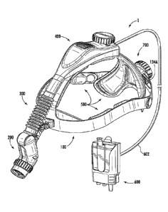
[00461 FIGS. 1-7 show
several perspective views of a head wearable
device, generally designated 1. In the embodiment shown, the head
wearable device 1 comprises an adjustable headpiece comprising a
headband, generally designated 100, which has a top strap 110 and at least
two lateral straps 120A/120B, and an occipital basket 150 attached to (e.g.,
removably, fixedly, and/or integrally) the headband 100; a luminaire,
generally designated 200, movably attached at the front of the headband
100, a duct system, generally designated 300, to direct exhaust air from the
luminaire 200 to a hot air exhaust 420 formed in the upper housing,
generally designated 400, that is attached to the top strap 110 of the head
wearable device 1; rear adjustment straps 130A/130B; a depth adjuster,
generally designated 450, and a headband adjuster, generally designated
700, that are for adjusting the size of the headband 100 to the size of a
11
CA 03114516 2021-03-26
WO 2020/072088 PCT/US2018/067231
wearer's head; a holster 600 with a battery pack and controller that is in
electrical communication, via power cord 602, with the luminaire 200 and an
air moving device (see 332, FIG. 8) associated with the duct system 300;
and a padding system, generally designated 500, installed on at least some
of the inner surfaces of the headband 100 and occipital basket 150. As
shown, the lateral straps 120A/120B, together with the rear adjustment
straps 130A/130B form a thin, flexible plastic ring of an approximately
elliptical shape for fitting horizontally on the head of a wearer. The upper
housing 400 can extend from the front to the rear (e.g., the occipital basket
150) of the headband 100, extend between the lateral straps 120A/120B of
the headband 100, or extend between any two points on the ring. Two or
more of these portions may form an integral piece, or operably or adjustably
connected to each other. Headband may be constructed with more or fewer
portions or straps than the embodiment shown and may take any shape. The
headbands may cover more or less surface of the wearer's head than the
embodiment as shown. While the headpiece is shown in this embodiment as
comprising the headband 100 and the occipital basket 150, the headpiece
may take any shape and may have a substantially continuous outer cover
that is either adjustable to a wearer's head size or of fixed dimensions.
Similarly, an outer shell may be provided around the headpiece, as needed
based on the environment in which the head wearable device is to be worn.
[0047] In the embodiment
shown, the headband 100 comprising the top
strap 110 and lateral straps 120A/120B is integrally formed from a single
piece. An example of this portion of the headband 100 is shown in FIGS. 9A
and 9B, with the top strap 110 and lateral straps 120A/120B being shown in
a substantially planar (i.e., flat), unformed, configuration. The top strap
110
has upper housing 400 affixed thereto, into which the top strap 152 from the
occipital basket 150 is inserted to connect the top strap 110 to the occipital
basket 150. The upper housing 400 has an outer shell 410, which has a slot,
generally designated 412, formed at a rear of the outer shell 410, into which
slot 412 the strap 152 of the occipital basket 150 is inserted to adjust the
depth of the head wearable device 1. The strap 152 of the occipital basket
12
CA 03114516 2021-03-26
WO 2020/072088 PCT/US2018/067231
150 has a slot (see 154, FIGS. 13-15) formed along the length thereof, the
length of the slot 154 defining a maximum amount of adjustment of the depth
of the head wearable device 1. As can be seen in greater detail in FIGS. 13-
15, the slot 154 of the strap 152 has, on at least one side thereof, a
plurality
of teeth 156 that are configured to interface with, and be moved by, a gear
470 that is rotatably mounted within the upper housing 400 in the form of a
rack-and-pinion arrangement. As such, a rotation of the top adjustment knob
460 and, accordingly, the top adjustment gear 470, causes the strap 152 of
the occipital basket 150 to be lengthened or shortened relative to the upper
housing 400 as the gear 470 draws the strap 152 into, or pushes the strap
152 out of, the upper housing 400. Due to the rack-and-pinion arrangement,
precise size adjustments to the depth of the head wearable device 1 are
contemplated. As such, a plurality of indexing marks, generally designated
157, are provided in an externally visible location on the strap 152 of the
occipital basket 150 so that the depth of the head wearable device 1 may be
easily and repeatably adjusted to a given value for a plurality of wearers of
the head wearable device 1.
[0048] The headband 100
is further connected to the occipital basket 150
by lateral extension straps 130A/130B, which are rotatably coupled to the
lateral straps 120A/120B, respectively, at respective hinges, generally
designated 140A/140B, which in this embodiment are circular hinges. Each
of the lateral extension straps 130A/130B wraps behind the occipital basket
150 and is inserted within a housing of the headband adjuster, generally
designated 700, which is shown on the rear external surface of the occipital
basket 150. As can be seen in FIGS. 9A and 9B, the lateral extension straps
130A/130B have a slot 132A/132B formed along the length thereof,
respectively, the length of the slot 132A/132B defining a maximum amount
of adjustment of the circumference of the head wearable device 1. The slot
132A/132B of each lateral extension strap 130A/130B has, on at least one
side thereof, a plurality of teeth 134A/134B that are configured to interface
with, and be moved by, a gear (see 730, FIG. 19) that is rotatably mounted
within the housing of the headband adjuster 700 in the form of a rack-and-
13
CA 03114516 2021-03-26
WO 2020/072088 PCT/US2018/067231
pinion arrangement. The plurality of teeth 134A on a first of the lateral
extension straps 130A are on an opposite side of the slot 132A from the
plurality of teeth 134B formed in the slot 132B of the second lateral
extension strap 130B, such that a rotating motion of the occipital basket
adjustment gear 730 causes a simultaneous expansion or contraction,
depending on the direction in which the knob 740 is rotated, of the headband
100 to correspondingly increase or decrease lateral circumference of the
head wearable device 1. Due to the rack-and-pinion arrangement, precise
size adjustments of the head wearable device 1 are contemplated. As such,
a plurality of indexing marks, generally designated 137, are provided in an
externally visible location on one or more of the lateral extension straps
130A/130B so that the head wearable device 1 may be easily and
repeatably adjusted to a given size for a plurality of wearers of the head
wearable device 1. The slots 132A/132B are shown as being closed at both
ends thereof to prevent the lateral extension straps 130A/130B from
becoming disengaged from the headband adjuster 700. As such, the lateral
extension straps 130A/130B are captively held within the headband adjuster
700 when worn by a wearer.
[0049] The hinges
140A/140B connecting the lateral straps 120A/120B of
the headband 100 to the lateral extension straps 130A/130B are configured
to pivot about an axis defined through the center of each respective hinge
140A/140B. Any type of hinge may be used and, in fact, the lateral
extension straps 130A/130B may be integrally formed with the lateral straps
120A/120B of the headband 100. However, it is advantageous to use the
circular hinges 140A/140B shown because, as the strap 152 is drawn into or
pushed out from the upper housing 400 on the headband 100 to alter a
depth of the head wearable device 1, the position of the occipital basket 150
changes at least vertically, relative to the lateral straps 120A/120B, such
that
the angle between the lateral straps 120A/120B and the lateral extension
straps lateral extension straps 130A/130B at the hinges 140A/140B can be
altered without deforming the lateral extension straps 130A/130B that might
cause any distortions or deformations thereof in the region of the slots
14
CA 03114516 2021-03-26
WO 2020/072088 PCT/US2018/067231
132A/132B, thereby preventing binding of the lateral extension straps
130A/130B within the housing of the headband adjuster 700.
[0050] A padding system
500 is attached to the inner surfaces of the
head wearable device 1, including the inner surfaces of the headband 100
and the occipital basket 150 where contact would otherwise occur with the
head of a wearer of the head wearable device 1. While any suitable type and
configuration of padding may be utilized for the padding system 500, the
embodiment shown has padding segments that are attached to the inner
surfaces of the headband 100 and the occipital basket 150. The padding
segments may be formed from any suitable material having a suitable
degree of padding to provide a desired amount of comfort for a wearer
during extended wearing times (e.g., on the order of multiple hours). The
padding system comprises a rear pad 550, side pads 520/530, and a top
pad 540 attached to the corresponding inner surfaces of the occipital basket
150, the lateral straps 120A/120B, and the top strap 110 of the head
wearable device 1, respectively. The padding system 500 may further
comprise a brow pad 510 attached to the inner surface of the headband at or
about an intersection of the top strap 110 and the lateral straps 120A/120B.
Each of the padding segments 510, 520, 530, 540, and 550 described herein
can be portions of a large integral pad and do not need to be separate pads.
[0051] The padding
segments 510, 520, 530, 540, and 550 are attached
to the headband 100 or the occipital basket 150, respectively, by any
suitable attachment type, including, for example, adhesive, interlocking
snaps, mechanical interlocking tabs, and the like. The padding segments
510, 520, 530, 540, and 550 may be contoured to the shape of the
respective strap or occipital basket 150 to which the padding segment 510,
520, 530, 540, and 550 is attached and may have a size less than or greater
than a width of the strap(s) to which each such padding segment 510, 520,
530, 540, and 550 is attached. As such, a brow pad is provided at the front
of the headband 100 at a position that would be against the forehead of a
wearer of the head wearable device 1. This brow pad 510 may extend, at
CA 03114516 2021-03-26
WO 2020/072088 PCT/US2018/067231
least to some extent, onto the top strap 110 and the two lateral straps
120A/120B. In the embodiment shown, the strap 152 of the occipital basket
150 and the lateral extension straps 130A/130B are devoid of padding
segments, not only because these portions are spaced apart from the
surface of the wearer's head while being worn, but also so that mechanical
interference does not occur between adjacent components as the
dimensions (e.g., the depth and/or the circumference) of the head wearable
device 1 is adjusted. In the embodiment shown, the padding segments 510,
520, 530, 540, and 550 can be removable for cleaning, maintenance, etc.
One or more of the padding segments 510, 520, 530, 540, and 550 can have
a different degree of softness from others of the padding segments 510, 520,
530, 540, and 550. One or more (e.g., each, or all) padding segments 510,
520, 530, 540, and 550 may have more than two layers of cushioning
material.
[0052] Referring to FIGS.
20-26, according to some embodiments of the
present disclosure, the rear pad 550 comprises a first layer 570 of a first
cushioning material having a first durometer, and a second layer 580 of a
second cushioning material having a second durometer that is harder than
the first durometer. In an example embodiment, the first cushioning material
is silicone foam, and the second cushioning material is also silicone foam,
but the silicone foam in the second layer 580 has a higher durometer than
the silicone foam in the first layer 570. For example, the durometer of the
second layer 580 can be 5%, 10%, 25%, or up to and including 50% higher
than the durometer of the first layer 570. In other words, the silicone foam
in
the second layer 580 is harder (e.g., less compliant) than the silicone foam
in
the first layer 570. The second layer 580 of the second cushioning material is
closer than the first layer 570 of the first cushioning material to the inner
surface of the occipital basket 150. The harder second layer 580 provides
support, while the softer, conforming first layer 570 is in closer contact
with
the wearer and provides increased comfort to the wearer of the head
wearable device 1.
16
CA 03114516 2021-03-26
WO 2020/072088 PCT/US2018/067231
[00531 Although FIG. 21
shows that the first layer 570 and the second
layer 580 of the respective cushioning materials have the same or similar
thickness, it is contemplated that the first layer 570 can have a different
thickness from the second layer 580. The thickness of each layer is
preferably no more than 1 inch (in.) and, more preferably, no more than 0.5
in., for example, about 0.25 in. In an example embodiment, the first layer
570, which is oriented towards (e.g., adjacent the head of) the wearer, is
1/4"
die-cut silicone foam (for example, BISCOO BF-2000, an ultra soft silicone
foam manufactured by Rogers Corporation) and the second layer 580, which
is oriented towards (e.g., adjacent the surface of) the occipital basket 150
is
1/4" die-cut silicone foam (for example, BISCOO HT-800, a medium cellular
silicone foam manufactured by Rogers Corporation), which can be either
open cell silicone foam or closed cell silicone foam. In some aspects, the
respective durometers of the silicone foam layers can be defined by
compression force deflection of the foam silicone. In some embodiments, the
durometer is within a range of about (e.g., 1%, 2%, 5%, 10%, 25%, or
50%) 10-70 Shore A, inclusive. HT-800 silicone foam has a density, as
measured according to ASTM D 1056, of 22 pounds per cubic feet (Ib/ft3).
BF-2000 silicone foam has a density, as measured according to ASTM D
1056, of 10 lb/ft3. For the first layer 570, the die-cut silicone foam (BF
2000)
can have a compression force deflection of about (e.g., 1%, 2%, 5%,
10%, 25%, or 50%) 1.5 pounds per square inch (psi). The compression
force deflection is a measure of the load bearing ability of a foam material
and is the force exerted against a flat compression foot that is larger than
the
specimen to be tested. The term compression force deflection is also
sometimes referred to as "compression load deflection". The compression
force deflection metric is measured as the force necessary to achieve a 25%
deflection according to ASTM D 1056. For the second layer 580, the die-cut
silicone foam (for example, BISCO HT-800) can have a compression force
deflection of within a range including, for example, about (e.g., 1%, 2%,
5%, 10%, 25%, or 50%) 6-14 psi. In some embodiments, the second
layer 580 of the second cushioning material 582 has more open space on its
upper or lower surface due to perforations than the first layer 570 of the
first
17
CA 03114516 2021-03-26
WO 2020/072088 PCT/US2018/067231
cushioning material 572, which has, in the embodiment shown, a surface
area of about 10.617 square inches (in2). In another aspect, the total surface
area of the cavities formed by the perforations 584 in the second layer 580 of
the second cushioning material 582 is higher than the total surface area of
the cavities formed by the perforations 574 in the first layer 570 of the
first
cushioning material 572, for example, the total surface area of the cavities
in
the second layer 580 is about 9.249 in2.
[0054] In some
embodiments, the perforation patterns can be chosen
taking into consideration the durometer (e.g., hardness) and density of each
layer specific to the cushioning material used. The perforations in the layers
of cushioning material also improve heat dissipation and air-flow. For the
rear pad 550, the volume of the first cushioning material 572 removed from
the first layer 570 in forming the plurality of perforations 574 is about
1.575
cubic inches (in3) and the volume of the second cushioning material 582
removed from the second layer 580 in forming the plurality of perforations
584 is about 5.112 in3.
[0055] According to
further embodiments of the present subject matter,
the first layer 570 of the first cushioning material 572 and the second layer
580 of the second cushioning material 582 are each perforated. As shown in
FIG. 22, the first layer 570 has a first perforation pattern comprising a
plurality of first perforations 574 formed therein. FIG. 23 shows the second
layer 580, which has a second perforation pattern comprising a plurality of
second perforations 584. The first perforation pattern and the first
perforations 574 differ from the second perforation pattern and the second
perforations 584. The first perforations 574 in the first layer 570 are
generally
arranged in a first perforation shape and the second perforations 584 in the
second layer 580 are generally in a second perforation shape, which may
differ from the first perforation shape. For example, the first perforations
574,
or at least the majority of the first perforations 574, in the first layer 570
of
the first cushioning material 572, are generally circular, and the second
perforations 584, or at least the majority of the second perforations 584, in
18
CA 03114516 2021-03-26
WO 2020/072088 PCT/US2018/067231
the second layer 580 of the second cushioning material 582 are in a shape
other than circular, such as generally square, rectangular, and/or triangular,
or generally in a grid-like pattern. The first and second perforations 574/584
are holes or apertures that pass through the thickness of the respective first
and second cushioning materials 572/582. The first and second perforations
574/584 can be created by die-cutting, piercing, boring, or any other
conventional methods.
[0056] A different
perforation pattern can be a result of a higher
perforation count of the perforation of the same shape, or perforations of a
different shape or different shapes, or a combination of the foregoing. In an
aspect of the present disclosure shown in FIG. 23, the second layer 580 of
the second cushioning material 582 has more open space on its upper or
lower surface due to second perforations 584 than the first layer 570 of the
first cushioning material 572. In another aspect of the present disclosure,
the
total volume of the cavities formed by the second perforations 584 in the
second layer 580 of the second cushioning material 582 is higher than the
total volume of the cavities formed by the first perforations 574 in the first
layer 570 of first cushioning material 572. The second layer 580 has a cut-
out recess, generally designated 586, which substantially defines the size,
shape, and/or contour of the cut-out recessed region 556 of the rear pad
550, the cut-out recess 586 and the cut-out recessed region 556 having a
size, shape, and/or contour that corresponds to the size, shape, and/or
contour of the cut-out 158 of the occipital basket 150.
[0057] In additional
embodiments of the present subject matter, the rear
pad 550 has an inner surface in contact with a wearer and an outer surface
attached to the inner surface of the rear portion of the headband, and the
rear pad 550 comprises a recess 576 formed in the first layer 570.
[0058] In each of the
respective padding segments 510, 520, 530, 540,
and 550, the cushioning material may be any suitable synthetic foam such
as silicone foam, expanded polystyrene, polyurethane, or other types of
19
CA 03114516 2021-03-26
WO 2020/072088 PCT/US2018/067231
polymer. In an example embodiment of the present disclosure, the
cushioning material in both layers are a silicone foam, for example, the
silicon foam materials commercially available at Stockwell Elastomerics, Inc.
The differences in the first and second layers 570/580 include the durometer
of the first and second cushioning materials 572/582. Any suitable material
may be used as long as the material has a similar durometer as the
materials specified herein.
[00591 As shown in FIGS.
24-26, the rear pad 550 is covered by a rear
pad cover 552, which can be made of fabric, synthetic polymers, or other
suitable materials, such as polyethylene, nylon, glass fibers and the like.
The
rear pad 550 comprises a recessed area 553 formed therein, between the
opposing padding lobes 554 that have, in the embodiment shown, a
generally triangular shape. The recessed area 553 is provided to relieve
pressure from the occipital basket 150 being secured over the rear portion of
the head of a wearer, thereby accommodating accessories worn by the
wearer, such as, for example, straps for the cap, loupe, or glasses and the
like, without interfering with the head wearable device 1 being sufficiently
secured over the wearer's head and to avoid pressure that may push against
the back of the wearer's head. Any shape for the rear pad 550 is
contemplated and, furthermore, the recessed area 553 can be in any shape,
including, as shown in FIG. 20, a generally triangular shape. Recessed area
553 can have a reduced thickness compared to the thickness of the rear pad
550 overall and/or to the padding lobes 554. In the example embodiment
shown, the rear pad cover 552 is able to sufficiently surround a rear pad 550
having a total volume of about 7.18 in3. In an example embodiment, the rear
pad cover 552 is made of Darlington 96630 fabric manufactured by
Darlington. The Darlington 96630 material used in the example embodiment
is a 4-way stretch heavy weight tricot, 356 gsm (grams per square meter)
weight, and is available in various colors. As shown in FIG. 26, the back of
rear pad cover 552 shown in FIG. 25 may be produced by layering a main
body piece 558A, two inner overlap pieces 558B and two netting pieces
558C in the order as illustrated, such that the back of the rear pad cover 552
CA 03114516 2021-03-26
WO 2020/072088
PCT/US2018/067231
has an elastic netting pocket 564 on the outer surface of each side flap. The
rear pad cover 552 comprises a cut-out recessed region 556 contoured to
the shape of the occipital basket 150 and also covers the recess 576.
Regardless of the materials specified herein, it is contemplated that at least
a portion of the rear pad cover 552 may be made from a breathable stretch
material with an estimated weight within the range of about 300-400 gsm
inclusive.
[00601 The
front of the rear pad cover 552 can be fabric such as
Darlington fabrics, 4-way stretch spandex, while the back of the rear pad
cover 552 can be nylon/UBL (unbroken loop) fabric 560, which is a part of a
hook-and-loop fastening system, with optional snaps 562 provided to more
securely attach the rear pad cover 552 over the rear pad 550. Other
materials are suitable for use in the padding system 500, and can be
selected depending on cleaning and comfort requirements.
[0061] The
rear pad 550 can be assembled by aligning the front of rear
pad cover 552 shown in FIG. 24, the first layer 570 of the first cushioning
material shown in FIG. 22, the second layer 580 of the second cushioning
material shown in FIG. 23, and the back of the rear pad cover 552 shown in
FIG. 25, and then sewing along the periphery of the covers. The stretch-
mesh netting pockets 564 on the back of the rear pad cover 552 is made of
an elastic material, such as spandex mesh, and is removably disposed about
the outer surface of the corresponding side flaps of the occipital basket 150
to help secure the rear pad cover 552 to the occipital basket 150. The recess
in the rear pad 550 can be formed by adding stitches along the
corresponding recess 576 in the first layer 570 of the first cushioning
material in the rear pad 550.
[00621 Referring to
FIGS. 27 and 28, the brow pad 510 comprises a first
layer 512 of a first cushioning material having a first durometer, and a
second layer 516 of a second cushioning material having a second
durometer that is different (e.g., harder) than the first durometer. The first
21
CA 03114516 2021-03-26
WO 2020/072088
PCT/US2018/067231
layer 512 is perforated in a first perforation pattern, comprising first
perforations 514, and the second layer 516 is perforated in a second
perforation pattern, comprising second perforations 518, which differ from
the first perforation pattern. In an example embodiment, the first layer 512
of
the first cushioning material of the brow pad 510 is configured as a comfort
layer arranged adjacent the head of the wearer and is formed from 1A" die-
cut silicone foam (BF 2000), while the second layer 516 of the second
cushioning material is spaced apart from the head of the wearer and is
formed 1/4" die-cut silicone foam (for example, BISCO HT-800).
[0063] Although the example embodiments of rear pad 550 and brow pad
510 both include a softer, inner, first layer of cushioning material and a
harder, outer, second layer of cushioning material, other layering options are
contemplated, depending on the cleanability and comfort standards and the
desired fit, feel, and comfort level. In some embodiments, the BISCOO
silicone foams disclosed herein can be described as being a range of
materials, including extra firm (HT-840), firm (HT-820), medium (HT-800),
soft (HT-870), extra soft (BF-1000), and ultra soft (BF-2000). HT-840 has a
compression force deflection within a range of 16-26 psi and, preferably, a
compression force deflection of 22 psi. HT-820 has a compression force
deflection range of 12-20 psi and, preferably, a compression force deflection
of 16 psi. HT-800 has a compression force deflection within a range of 6-14
psi and, preferably, a compression force deflection of 9 psi. HT-870 has a
compression force deflection within a range of 2-7 psi and, preferably, a
compression force deflection of 4 psi. BF-1000 has a compression force
deflection within a range of 1-5 psi and, preferably, a compression force
deflection of 3 psi. BF-2000 has a compression force deflection of about 1.5
psi. Some other possible combinations of generally hard, medium, and soft
layers include medium inner - medium outer, hard outer - medium inner, and
soft outer - soft outer layering combinations. Any of the extra firm, firm,
medium, soft, extra soft, and ultra soft materials may be combined to form
the first and second layers of padding.
22
CA 03114516 2021-03-26
WO 2020/072088 PCT/US2018/067231
[0064] Examples of such
combinations for any of padding segments 510,
520, 530, 540, and 550 can include a first layer comprising extra firm (having
a first durometer with a compression force deflection in a range of 16-26 psi)
silicone foam and a second layer comprising silicone foam of any of the
following types: firm (having a second durometer with a compression force
deflection in a range of 12-20 psi), medium (having a second durometer with
a compression force deflection in a range of 6-14 psi), soft (having a second
durometer with a compression force deflection in a range of 2-7 psi), extra
soft (having a second durometer with a compression force deflection in a
range of 1-5 psi), or ultra soft (having a second durometer with a
compression force deflection of about 1.5 psi).
[0065] Other examples of
such combinations for any of padding
segments 510, 520, 530, 540, and 550 can include a first layer comprising
firm (having a first durometer with a compression force deflection in a range
of 12-20 psi) silicone foam and a second layer comprising silicone foam of
any of the following types: extra firm (having a second durometer with a
compression force deflection in a range of 16-26 psi), medium (having a
second durometer with a compression force deflection in a range of 6-14
psi), soft (having a second durometer with a compression force deflection in
a range of 2-7 psi), extra soft (having a second durometer with a
compression force deflection in a range of 1-5 psi), or ultra soft (having a
second durometer with a compression force deflection of about 1.5 psi).
[0066] Another set of
examples of such combinations for any of padding
segments 510, 520, 530, 540, and 550 can include a first layer comprising
medium (having a first durometer with a compression force deflection in a
range of 6-14 psi) silicone foam and a second layer comprising silicone foam
of any of the following types: extra firm (having a second durometer with a
compression force deflection in a range of 16-26 psi), firm (having a second
durometer with a compression force deflection in a range of 12-20 psi), soft
(having a second durometer with a compression force deflection in a range
of 2-7 psi), extra soft (having a second durometer with a compression force
23
CA 03114516 2021-03-26
WO 2020/072088 PCT/US2018/067231
deflection in a range of 1-5 psi), or ultra soft (having a second durometer
with a compression force deflection of about 1.5 psi).
[0067] In still other
examples, such combinations for any of padding
segments 510, 520, 530, 540, and 550 can include a first layer comprising
soft (having a first durometer with a compression force deflection in a range
of 2-7 psi) silicone foam and a second layer comprising silicone foam of any
of the following types: extra firm (having a second durometer with a
compression force deflection in a range of 16-26 psi), firm (having a second
durometer with a compression force deflection in a range of 12-20 psi),
medium (having a second durometer with a compression force deflection in
a range of 6-14 psi), extra soft (having a second durometer with a
compression force deflection in a range of 1-5 psi), or ultra soft (having a
second durometer with a compression force deflection of about 1.5 psi).
[0068] In further
examples, such combinations for any of padding
segments 510, 520, 530, 540, and 550 can include a first layer comprising
extra soft (having a first durometer with a compression force deflection in a
range of 1-5 psi) silicone foam and a second layer comprising silicone foam
of any of the following
types: extra firm (having a second durometer with a
compression force deflection in a range of 16-26 psi), firm (having a second
durometer with a compression force deflection in a range of 12-20 psi),
medium (having a second durometer with a compression force deflection in
a range of 6-14 psi), soft (having a second durometer with a compression
force deflection in a range of 2-7 psi), or ultra soft (having a second
durometer with a compression force deflection of about 1.5 psi).
[0069] In yet further
examples, such combinations for any of padding
segments 510, 520, 530, 540, and 550 can include a first layer comprising
ultra soft (having a first durometer with a compression force deflection of
about 1.5 psi) silicone foam and a second layer comprising silicone foam of
any of the following types: extra firm (having a second durometer with a
compression force deflection in a range of 16-26 psi), firm (having a second
24
CA 03114516 2021-03-26
WO 2020/072088
PCT/US2018/067231
durometer with a compression force deflection in a range of 12-20 psi),
medium (having a second durometer with a compression force deflection in
a range of 6-14 psi), soft (having a second durometer with a compression
force deflection in a range of 2-7 psi), or extra soft (having a second
durometer with a compression force deflection in a range of 1-5 psi).
[0070] In
some embodiments, the second layer 516 of the second
cushioning material has more open space on its upper or lower surface due
to perforations than the first layer 512 of the first cushioning material,
which
has, in the embodiment shown, a surface area of about 7.712 in2. In another
aspect, the total surface area of the cavities formed by the perforations 518
in the second layer 516 of the second cushioning material is higher than the
total surface area of the cavities formed by the perforations 514 in the first
layer 512 of the first cushioning material, for example, the total surface
area
of the cavities in the second layer 516 is about 5.858 in2.
[0071] In
some embodiments, the perforation patterns can be chosen
taking into consideration the durometer (e.g., hardness) and density of each
layer specific to the cushioning material used. The perforations in the layers
of cushioning material also improve heat dissipation and air-flow. For the
brow pad 510, the volume of the first cushioning material removed from the
first layer 512 in forming the plurality of perforations 514 is about 1.179
in3
and the volume of the second cushioning material removed from the second
layer 516 in forming the plurality of perforations 518 is about 3.033 in3.
[0072] The differences between the respective first and second
perforation patterns can also aid in visually deciphering the first layer 512
from the second layer 516. The outer layer of primarily circle die-cuts may be
laid out over the grid formed by the second perforations 518 formed in the
second layer 516 to optimize air-flow between the first layer 512 and the
second layer 516. Additionally, a higher perforation count may be used in the
first layer 512 on the foam to increase the degree of compression and
softness of the first compression material. The first perforations 514
CA 03114516 2021-03-26
WO 2020/072088
PCT/US2018/067231
comprise round holes to provide flexibility to explore actual hole count
among the different designs, but as described above the first perforations
514 do not have to be circular. The actual design and perforation patterns
should take into account the amount of material removed, not simply the
shape of the die-cuts.
[0073]
Referring to FIGS. 29 and 30, the top cover 522/532 of the side
pads 520/530 can be made of fabric, for example, Darlington 96630 fabric
manufactured by Darlington, which is a 4-way stretch Heavy Weight Tricot
with a 356 gsm weight. The pad shown here is a side pad 520/530 for one
side portion of the headband 100. The side pad 520/530 for the other side
portion of the headband 100 is a mirror image of the side pad 520/530 as
shown.
[0074] The rear 526/536
of the side pad 520/530 includes an attachment
that secures the side pad 520/530 to the lateral strap 120A/120B of the
headband 100. An example of a suitable attachment includes a hook-and-
loop fastener system. The side pad 520/530 is filled with open-cell urethane
foam or other suitable cushioning material to provide the desired level of
support and comfort. A depression 524/534 can be formed by stitching
across the side pad 520/530, thereby creating two or more padding
segments in the side pad 520/530.
[0075]
Referring to FIGS. 31 and 32, like the side pad shown in FIGS. 29
and 30, the top pad 540 can be made of fabric, for example, Darlington
96630 fabric. In the embodiment shown, the rear 546 of the top pad 540
includes a hook and loop fastener strip. Other suitable attachment types are
contemplated. The top pad 540 is filled with open-cell urethane foam or any
other suitable cushioning material, and the foam can be of any suitable
thickness, for example, 3/4" urethane foam support.
[0076]
Although the top pad 540 and the side pad 520/530 are described
herein each in singular form, there may be more than one top pad 540 and
26
CA 03114516 2021-03-26
WO 2020/072088
PCT/US2018/067231
at least two side pads 520/530 for the two lateral straps 120A/120B of the
headband 100. Each of these pads may have similar constructions but
different shapes, lengths, thickness, curvatures, and the like to adapt the
respective pad to the corresponding contour of the strap of the headband
100 for attachment. In addition, although the respective pads are shown as
segmented pieces, one or more of the padding segments may be connected
or all may be formed as an integral portion of the padding system 500.
[00771 The
padding segments 510, 520, 530, 540, and 550 in the
padding system 500 can be attached the headband 100 and the occipital
basket 150 in various ways, either permanently or removably, for example,
by hook and loop fasteners, snapping members, stitching, adhesive, ties,
and any other suitable types of attachment known in the art. In an example
embodiment, the brow, side and top pads 510, 520, 530, and 540 are all
backed with a die-cut loop material to anchor them to the headband 100.
[00781 The
occipital basket 150 comprises at least one padding segment
550 removably attached thereto. As shown in FIG. 16, the occipital basket
150 comprises a cut-out 158, or notch, formed at the bottom edge thereof
that defines a location where a wearer's hair can exit the occipital basket
150
without substantially interfering with the occipital basket 150 fitting
securely
against the rear of the wearer's head. The cut-out 158 is also formed to
accommodate any features of a head wearable garment (e.g., a knot used to
secure a surgical cap over the head of the wearer). In the embodiment of
FIGS. 1-7, the rear pad 550 is a unitary (e.g., integral or monolithic)
padding
segment that is attached to the occipital basket 150 by a retention strap 566
(see FIG. 25) and netting 564 (see FIG. 25) that contain each of the lower
corners of the occipital basket 150 (e.g., on opposite sides of the cut-out)
therein and an upper strap 560 (see FIG. 25) which passes around the strap
152 of the occipital basket 150 and is secured thereto by snaps 562 (see
FIG. 25) or any other suitable fastener. As shown at least in FIG. 16, the
rear
pad 550 on the occipital basket 150 has an outer contour/profile shape that
is substantially similar to that of the occipital basket 150 itself, including
the
27
CA 03114516 2021-03-26
WO 2020/072088
PCT/US2018/067231
cut-out 158. Furthermore, the rear pad 550 on the occipital basket 150
comprises a cut-out recessed region 556 to accommodate a wearer's hair
style without interfering with the head wearable device 1 being sufficiently
secured over the wearer's head and to avoid pressure that may push against
the back of the wearer's head.
[0079] FIG.
33 shows an embodiment of the head wearable device 1,
similar to that shown in FIGS. 1-7, fitted on and over a human skull,
generally designated 800, to demonstrate possible and what can be
preferred placement of the padding segments (e.g., 510, 520, 530, 540, 550)
relative to skull region joinder lines or sutures, such as for example sutures
810, 820, 830, and/or 840, that exist between adjacent skull plates of the
skull 800 and are configured to be positioned on a head without covering or
being disposed or positioned over any or a substantial portion of the skull
sutures such as sutures 810 shown. As shown, the padding segments are
spaced such that, in at least some configurations, the weight of the head
wearable device 1 is not placed on or over the skull sutures. For example,
the shape of the lateral straps 120A/120B and the hinges 140A/140B avoid
placement over, and do not contact and/or put pressure on, the squamous
suture 830 and the lambdoid suture 820, while the top pad 540 does not
contact at least a portion of the sagittal suture 840. As such, the side pads
520/530 of the lateral straps 140A/140B do not contact or apply pressure
over any suture (e.g., 810, 820, 830, and/or 840) of the skull 800 of the
wearer of the head wearable device 1. In the embodiment shown, a gap,
generally designated 542, is present between segments of the top pad 540
so that the top pad 540 does not contact the head of the wearer in a region
covering or over the coronal suture 810 of the skull 800 of the wearer. Stated
differently, the top pad 540 is spaced apart from the head of the wearer over
one or more sutures 810 of the wearer's skull 800. As such, the top pad 540
does not contact the wearer's head at areas of the sutures 810 of the
wearer's skull 800. A gap, generally designated 522, 532, is present
between segments of the side pads 520, 530 so that the side pads 520, 530
do not contact the head of the wearer in a region covering or over a suture
28
CA 03114516 2021-03-26
WO 2020/072088
PCT/US2018/067231
810 of the skull 800 of the wearer. The side pad 520, 530 is therefore
against the head but can be laterally spaced apart from the head of the
wearer over one or more sutures 810 of the wearer's skull 800. As such, the
side pads 520, 530 do not contact the wearer's skull at the sutures 810 of
the wearer's skull 800. In some embodiments, the top pad 540 and/or the
side pads 520, 530 can be adjusted positionally so that the gap 522, 532,
542 can be positioned over the suture 810 of the skull of the wearer to
provide enhanced comfort for the wearer during extended periods of use of
the head wearable device 1. While FIG. 33 is a view of one side of the head
wearable device 1 over a skull 800 of the wearer, the opposing view is
identical to (e.g., is a mirror image of) the side view of FIG. 36, such that
the
features shown therein and described hereinabove are present for both
sides of the head wearable device 1 relative to the skull 800 of the wearer.
[0080] The
luminaire 200 comprises an external housing 210 and is
attached at the forward edge of the headband 100 by any suitable
mechanical linkage, generally designated 350. In some embodiments, the
mechanical linkage 350 is a statically attached mounting point to which the
luminaire 200 is rigidly and/or pivotably attached. In the embodiment shown,
the mechanical linkage 350 comprises a mount that is connected to the front
of the headband 100 and linkage bars 354 that are pivotably connected
together by linkage rollers 356. As shown in FIG. 17, the mechanical linkage
350 is secured to the headband 100 by mounting hardware (e.g., screws
and washers), generally designated 358, which pass through the thickness
of the headband 100 at the front thereof. The mechanical linkage 350 is
provided to allow the angle of the luminaire 200 relative to the headband 100
and the distance of the luminaire 200 from the headband 100 to be
controlled independently. The luminaire 200 comprises, as is shown at least
partially in FIGS. 10-12, at least one LED 232 (e.g., any suitable light
source), which can be mounted on a substrate. Such a substrate can be
affixed (e.g., rigidly) to a heatsink 220 located within the luminaire housing
210 to conduct heat generated by the at least one LED 232 into the heatsink
220. Such a substrate can have surface-mount connection points for the
29
CA 03114516 2021-03-26
WO 2020/072088 PCT/US2018/067231
LED's power and sensing electrical needs. The substrate can be formed
such that the LED 232 and the heatsink 220 are located in opposing first and
second regions of the luminaire housing 210, the first region being adjacent
the lens cell and the second region being located away from (e.g., spaced
apart from) the LED 232. The substrate may be configured to allow for a
straight-line optical cell configuration, as opposed to a bent-configuration,
thereby eliminating the need for a mirror to perform the optical bend
necessary for such configurations. In some embodiments, such a substrate
can be a laminated printed circuit board (PCB) and/or comprises copper to
provide enhanced thermal conductivity between the LED 232 and the
heatsink 220 to the substrate. The use of copper in such a substrate can be
advantageous, as copper's high thermal conductivity allows for the efficient
conduction of heat from the LED 232 to the heatsink 220 for dissipation into
a cooling air stream flowing into the luminaire housing 210 via the inlet 212,
two of which are formed on opposing sides of the luminaire housing 210.
The heatsink 220 can be of any suitable construction, including, for example,
extrusion, soldering, skiving, and the like, and can comprise any suitably
conductive material, such as, for example, aluminum or copper.
[0081] The luminaire
housing 210 is connected, via a pivoting ball joint
310, to a duct 300 system. The ball joint 310 is formed of two half-members
311 assembled together to form the ball joint 310 and the luminaire housing
210 is clamped around the outer lateral edges of the ball joint 310 to allow
the luminaire housing 210 to rotate independently of and about the ball joint
310. The ball joint 310 is rotatable about an axis that is perpendicular to
the
duct system 300, unlike known solutions that rotate about an axis parallel to
the air flow path to avoid inducing kinks or other obstructions into the air
flow
path. The ball joint 310 has a hole 312 formed radially about a portion of the
circumference of the ball joint 310. The ball joint 310 has an exhaust port
314 formed in the circumference of the ball joint 310 and directed radially
away from the center of the ball joint 310. The exhaust port 314 and the hole
312 are located around the circumference of the ball joint 310. As such, the
ball joint 312 defines an airflow path through the body thereof, with the hole
CA 03114516 2021-03-26
WO 2020/072088 PCT/US2018/067231
312 and the exhaust port 314 being defined, respectively, as the inlet and
the outlet of the airflow path through the ball joint 310. The cross-sectional
area of the hole 312 has a size to provide sufficient air flow across the
heatsink 220 of the luminaire 200 to sufficiently cool the LED 232. In the
embodiment shown, the hole 312 and the exhaust port 314 are formed such
that they are located substantially diametrically opposite each other about
the circumference of the ball joint 310. The ball joint 310 has locating
features 317 formed therein and/or thereon that define a range of rotary
movement of the luminaire housing 210 and the ball joint 310 relative to
each other. This range of rotary movement defined by the locating features
317 is such that the hole 312 remains positioned internal to the luminaire
housing 210 at all operating positions of the luminaire 200 relative to the
headband 100 to avoid creating an unwanted air inlet in the luminaire
housing 210 upstream of the heatsink 220. Similarly, the lateral sides 315 of
the ball joint 310 can be solid or be sealed with a gasket to prevent any air
leakage into and/or out of the duct system 300. In some embodiments, such
as is shown in FIG. 12, the hole 312 comprises two discrete holes 312, one
hole 312 being formed in each side of the two half-members 311 of the ball
joint 10
[00821 The ball joint 310
is lockingly connected at the exhaust port 314
thereof to a flexible duct 320 that can have, for example, a corrugated
construction that allows for bending deflections as well as elongations or
contractions thereof when the position of the luminaire 200 relative to the
headband 100 is changed (e.g., by adjusting the position of the mechanical
linkage 350). The exhaust port 314 of the ball joint 310 comprises, in the
embodiment shown, a snapping interlock system 318 to ensure sufficient
mechanical interlocking between the exhaust port 314 and the flexible duct
320. The flexible duct 320 is connected at a distal end thereof to a rigid
duct
330 attached to the upper housing 400 on the top strap of the headband.
This rigid duct 330 has, at a distal end thereof from the flexible duct 320,
an
air moving device 332 attached thereto, the outlet of the air moving device
332 being oriented to blow out from a hot air exhaust 420. The luminaire
31
CA 03114516 2021-03-26
WO 2020/072088 PCT/US2018/067231
housing 210 has at least two air inlets 212 formed therein (e.g., integrally)
at
locations configured to draw ambient air across the heatsink 220. The air
moving device 332 can be of any suitable type, including a fan, blower,
piezoelectric device, or the like.
[0083] A sensor is
provided to monitor a temperature of the LED, either
directly or indirectly, and a controller is provided to thermostatically
control
the air moving device 332 to maintain the temperature of the LED 232 within
a prescribed operating temperature range. In examples of indirect thermal
management, the temperature of a substrate to which the LED 232 may be
attached and/or mounted, the heatsink 220, and/or the air flow passing
through the duct system 300 may be monitored, preferably in conjunction
with the operational state (e.g., as a percentage of maximum air flow) of the
air moving device 332. Gaskets 335 are provided on the inlet and/or the
outlet faces of the air moving device 332 to prevent introducing leakage
paths within the duct system 300.
[0084] In some
embodiments, the ball joint 310 comprises two half-
members 311 ultrasonically welded together to form the body of the ball joint
310, which is held in place within an end of the luminaire housing 210
sealingly clamped between flanges thereof, which may, in some
embodiments, itself be ultrasonically welded together from separate and
discrete housing members 210A/210B. This sealing clamping of the
luminaire housing 210 about the ball joint 310 can, in some embodiments,
be achieved by placing one or more gaskets circumferentially between the
ball joint-luminaire housing interface being sealed. In some such
embodiments, the one or more gaskets can be installed within a groove
formed in a surface of the ball joint 310, the luminaire housing 210, or both.
The two half-members 311 have a central cavity, generally designated 313,
formed therein when assembled together. In the embodiment shown, the ball
joint 310 sits loosely (e.g., sufficiently loose to allow the pivoting motion
of
the luminaire housing 210 relative to the ball join 310) at the proximal end
(relative to the headpiece) of the luminaire housing 210, with 0-ring gaskets
32
CA 03114516 2021-03-26
WO 2020/072088 PCT/US2018/067231
being provided in a recess around central protrusion 316 to produce an air
tight interface between the ball joint 310 and the luminaire housing 210 to
minimize leakage paths in the airflow path. As shown, the ball joint 310 can
pivot freely within the proximal end of the luminaire housing 210 over a
range of motion as determined by the vertical position of both the luminaire
200 and any accompanying downstream exhaust components (e.g., the
flexible duct 320, the rigid duct 330, etc.). The housing 210 is connected to
the mechanical linkage 350 at mounting tab 214.
[00851 As such, a method
of cooling a luminaire 200 of a head wearable
device 1 is provided. The method comprises providing an LED 232 within a
luminaire housing 210, forming at least one air inlet 212 in the luminaire
housing 210, attaching a heatsink 220, directly or indirectly (e.g., via a
substrate) to the LED 232, arranging the heatsink 220 adjacent the at least
one air inlet 212 of the luminaire housing 210, connecting the luminaire
housing 210 to the ball joint 310, forming a hole 312 and an exhaust port
314 in the ball joint 310, connecting a first end of the flexible duct 320 to
the
ball joint 310 at the exhaust port 314, connecting a rigid duct 330 to the
flexible duct 320 at the second end of the flexible duct 320, installing the
air
moving device 332 within a hot air exhaust 420 of the upper housing 400,
monitoring the temperature of the LED 232 within the luminaire 200, and
controlling the air moving device 332 to produce an air flow from the at least
one inlet 212 in the luminaire housing 210, through the heatsink 220,
through the ball joint 310, through the flexible duct 320, through the rigid
duct 330, through the air moving device 332, and exhausted from the hot air
exhaust 420 formed in the upper housing 400, which is attached to a top
strap 110 of a headband 100 of the head wearable device 1.
[00861 Power can be
provided to the head wearable device 1 via a power
cord 602 attached to the upper housing 400. In some embodiments, the
power cord 602 is of a twist-lock type, such that power cannot be
accidentally disconnected from the head wearable device 1 merely by pulling
the power cord 602 out of the holster 600 without an accompanying twisting
33
CA 03114516 2021-03-26
WO 2020/072088 PCT/US2018/067231
motion at the connector interface. The power cord 602 may be connected to
a holster 600 that is wearably attached to a wearer of the head wearable
device 1. In some embodiments, the holster 600 is configured to have one or
more battery packs installed therein, which allows the wearer of the head
wearable device 1 unrestricted movement. In some embodiments, the
holster 600 is configured to be connected to a substantially continuous
power source (e.g., a wall electrical outlet) for substantially indefinite
operation. The holster 600 comprises an intensity control (e.g., a rotary
control knob) that regulates power to the LED 232 from either battery or the
direct power supply and controls the intensity emitted from the LED 232 and,
consequently, also from the luminaire 200.
[00871 The luminaire 200
is configured to produce a pure white light
output without a yellow ring being present around the perimeter of the light
output area. Apertures may be used in optical devices such as cameras and
telescopes to limit light entering the device. Such apertures may be
manufactured from any suitable material, including from a thin metal and
may, in some aspects, advantageously be either anodized black or painted
black to minimize unwanted reflections within the optical path. It is known
that such apertures may be suspended mechanically within the lens cell in
any manner and orientation, as dictated by the optical design and
subsequent testing iterations. The presently disclosed luminaire 200 is thus
configured to restrict unwanted stray light (aberrations) from exiting the
optical path, thereby ensuring a near ideal white-spot presentation. It is
known that aberrations in the spot presentation can result from light
scattering in the optical train due to source light reflections off of
internal
mechanical components, LED "yellow light phenomenon," and the like. It is
advantageous to ensure that the optical train will yield a substantially
homogeneous white-spot presentation. The presently disclosed embodiment
optimizes the projection of white light while helping to restrict both stray
light
reflections and yellow light from exiting the optical path. As shown, the
light
projecting portion of the luminaire 200 is configured to produce a white-spot
presentation having an adjustable focal point and/or focal length, thereby
34
CA 03114516 2021-03-26
WO 2020/072088
PCT/US2018/067231
allowing for a white-spot presentation having an adjustable size (e.g.,
diameter). The focal length and spotlight size is adjustable by turning the
adjustment knob 202 (see FIG. 12) provided on the luminaire 200. The outer
lens 206 is contained within an outer lens structure, generally 204, at the
outlet of the optical train.
[0088] FIG.
17 is a partially exploded view of the head wearable device 1,
showing the attachment of the luminaire 200, via the mechanical linkage
350, to the headband 100 and the flexible duct 320 to the rigid duct 330.
FIG. 18 is a partially exploded view of the components of the depth adjuster
450 for the position of the strap 152 of the occipital basket 150 relative to
the
upper housing 410 attached to the top strap 110 of the headband 100. In
some embodiments, the occipital basket 150 is pivotable to better adjust to
the head shape of the wearer. The depth adjuster 450 shown in FIG. 18
comprises a gear 470 that engages with teeth 156 (see FIGS. 13-15) formed
on the inner surface of the slot 154 (see FIGS. 13-15) of the strap 152 that
is
being positionally adjusted relative to the upper housing 400 and the top
strap 110. The gear 470 projects through the upper housing 400 and is
fixedly and rotationally coupled to an adjustment knob 460. The adjustment
knob 460 is rotatably locked to the gear 470 by connector plate 462 and
screw 472. A cover plate 464 is attached to the adjustment knob 460, but in
some embodiments the cover plate 464 can be integrally formed as the
adjustment knob 460. As such, a rotary movement of the knob 460 causes a
corresponding rotary movement of the gear 470 and a corresponding
lengthening or shortening of the strap 152 which engages with the gear 470.
FIG. 19 is a partially exploded view of the components of the headband
adjuster 700 for the circumference of the head wearable device 1. The
headband adjuster 700 shown in FIG. 19 is largely similar to the depth
adjuster shown in FIG. 18, but the rear housing comprises a two-part rear
housing that has a base 710 that allows for visualization of the engagement
of the teeth 134A/134B of the lateral extension straps 130A/130B with the
gear 730 when assembling the head wearable device 1. This visualization
internal to the headband adjuster 700 ensures that the lateral extension
CA 03114516 2021-03-26
WO 2020/072088 PCT/US2018/067231
straps 130A/130B are each equally engaged around the gear 730 so the
components of the head wearable device 1 are symmetrical about a vertical
plane arranged along the longitudinal axis of the head wearable device 1.
The headband adjuster 700 further comprises a cover panel 720 that
engages at least partially over the base 710 to obscure the engagement of
the gear 730 with the lateral extension straps 130A/130B during normal
operation of the head wearable device 1. The gear 730 projects through a
hole formed in the occipital basket 150 and the base 710 is secured to the
occipital basket 150 at a predetermined mounting point, for example, by
screws 722. The gear 730 is then fixedly and rotationally coupled to an
adjustment knob 740 by screw 732, which passes through the occipital
basket 150. The adjustment knob 460 is rotatably locked to the gear 730 by
connector plate 742 and screw 732. A cover plate 744 is attached to the
adjustment knob 740, but in some embodiments the cover plate 744 can be
integrally formed as the adjustment knob 740. As such, a rotary movement
of the adjustment knob 740 causes a corresponding rotary movement of the
gear 730 and a corresponding lengthening or shortening of the
circumference of the head wearable device 1.
[00891 A method of
adjusting a size of a headpiece of a head wearable
device to a head size of a wearer, the headpiece comprising a headband
100 and an occipital basket 150, is provided. The method comprises
attaching an upper housing 400 to an external surface of a top strap 110 of
the headband 100; inserting a strap 152 of the occipital basket 150 at least
partially into the upper housing 400; engaging a first gear 470 with a
plurality
of teeth 156 formed in a slot 154, which is longitudinally oriented along a
length of the strap 152 of the occipital basket 150; turning a first
adjustment
knob 460, which is rotationally locked to the first adjustment gear 470, to
adjust a depth of the headpiece; attaching a second housing to an external
surface of the occipital basket 150; inserting an end of at least two lateral
extension straps 130A/130B into the second housing, with the end of a first
lateral extension strap 130A being inserted from an opposite end of the
housing from the end of a second lateral extension strap 130B, wherein the
36
CA 03114516 2021-03-26
WO 2020/072088
PCT/US2018/067231
two lateral extension straps 130A/130B are hingedly attached to lateral
straps 120A/120B of the headband 100 to define a circumference of the
headpiece; engaging a second gear 730 with a plurality of teeth 134A/134B
formed in a slot 132A/132B of each of the lateral extension straps
130A/130B such that the second gear 730 is engaged with both of the
lateral extension straps 130A/130B; and turning a second adjustment knob
740, which is rotationally locked to the second adjustment gear 730, to
adjust a circumference of the headpiece.
[0090] In some
embodiments, the method comprises providing a first
visual index along a length of the strap 152 of the occipital basket 150, the
first visual index 157 comprising sequential alphanumeric characters to
designate predetermined depth settings for the headpiece; providing a
second visual index 136 along a length of at least one of the lateral
extension straps 130A/130B, the second visual index 136 comprising
sequential alphanumeric characters to designate predetermined
circumference settings for the head wearable device 1; determining a wearer
preference for the depth and circumference of the head wearable device
1 corresponding to the first and second visual indexes 157/136; placing the
head wearable device 1 on the wearer's head; adjusting the first adjustment
knob 460 such that the first visual index 157 indicates that the wearer
preference for the depth of the head wearable device 1 has been achieved;
and adjusting the second adjustment knob 730 such that the second visual
index 136 indicates that the wearer preference for the circumference of the
head wearable device 1 has been achieved.
[0091] In
some aspects, a head wearable device comprises a headpiece;
a housing attached to the headpiece; a luminaire attached to the headpiece,
the luminaire comprising a luminaire housing and at least one light source
located within the luminaire housing; a duct system connecting the luminaire
to the housing; a ball joint rotatably connecting the duct system to the
luminaire; and an air moving device configured to induce a cooling air flow
through an inlet in the luminaire housing, through the heatsink, through the
37
CA 03114516 2021-03-26
WO 2020/072088
PCT/US2018/067231
ball joint, through the duct system, and out of an exhaust in the housing on
the top surface of the headpiece. In some embodiments of the head
wearable device, the housing is attached to a top surface of the headpiece
In some embodiments, the head wearable device comprises a controller
configured to monitor a temperature of the at least one light source and to
modulate an operational setting of the air moving device to maintain the
temperature of the at least one light source within a predetermined operating
range. In some embodiments of the head wearable device, the headpiece
comprises a headband, which has at least a top strap and two lateral straps,
and an occipital basket, wherein the headband is connected to the occipital
basket and the headband and the occipital basket are independently
adjustable relative to each other. In some embodiments of the head
wearable device, the at least one light source comprises a light emitting
diode (LED). In some embodiments of the head wearable device, the ball
joint is pivotably and/or swivelably connected to the luminaire. In some
embodiments of the head wearable device, the duct system comprises a
flexible duct connected to a rigid duct. In some embodiments of the head
wearable device, the air moving device is positioned inside the housing,
within the rigid duct, in a position adjacent to the exhaust in the housing.
In
some embodiments of the head wearable device, the luminaire is attached to
the headpiece by a mechanical linkage such that an angle and/or position of
the luminaire relative to the headpiece is adjustable. In some embodiments
of the head wearable device, the flexible duct comprises a corrugated
construction such that a length thereof can be shortened or lengthened as
the angle and/or position of the luminaire relative to the headpiece is
adjusted. In some embodiments of the head wearable device, the ball joint
defines a range of angular motion for the luminaire and comprises a passage
and an exhaust port formed in a circumferential wall of the ball joint, the
range of angular motion being such that the passage remains in a position to
provide an air flow path from the luminaire housing into the ball joint. In
some
embodiments of the head wearable device, the passage and the exhaust
port are arranged on substantially opposite sides of the ball joint. In some
embodiments of the head wearable device, the passage is not externally
38
CA 03114516 2021-03-26
WO 2020/072088
PCT/US2018/067231
visible from the luminaire housing at any point along the range of angular
motion. In some embodiments, the head wearable device comprises a
heatsink located within the luminaire housing. In some embodiments of the
head wearable device, the luminaire is configured to optimize a projection of
white light and restrict both stray light reflections and yellow light from
exiting
the lens cell. In some embodiments of the head wearable device, the lens
cell is configured to produce a substantially homogeneous white-spot
presentation. In some embodiments of the head wearable device, the lens
cell comprises an adjustable focal length and/or focal point. In some
embodiments, the head wearable device comprises a power cord attached
to the upper housing attached to the top strap of the headband, the power
cord being configured to receive power from a holster. In some embodiments
of the head wearable device, the power is provided from a rechargeable
battery or a continuous power source, and wherein the holster is configured
to adjust an intensity of light output from the at least one light source.
[0092] In
some aspects, a head wearable device comprises a headpiece
comprising: a headband comprising a top strap and at least two lateral
straps; an occipital basket comprising a strap, the occipital basket being
attached to the headband by at least one lateral extension strap pivotably
attached by a hinge to a distal end of each respective lateral strap of the
headband; a first housing attached to an outer surface of the top strap of the
headband; a depth adjuster attached to the first housing, the depth adjuster
comprising a first gear rotatably fixed to a first knob; wherein the strap of
the
occipital basket comprises a slot with a plurality of teeth formed around a
longitudinal edge of the slot; wherein the first gear is captively held within
the
slot and engages with the plurality of teeth; wherein the depth adjuster is
configured such that a rotary movement of the first gear causes a
longitudinal movement of the strap of the occipital basket to change a
distance between the occipital basket and the first housing; wherein a depth
of the headpiece changes when the distance between the occipital basket
and the first housing changes, or increases or decreases; and wherein the
strap comprises a first visual index comprising a first plurality of
sequential
39
CA 03114516 2021-03-26
WO 2020/072088
PCT/US2018/067231
characters, each of which correspond to one of a plurality of predetermined
depth settings of the headpiece; and a second housing attached to an outer
surface of the occipital basket; a headband adjuster at an outer surface of
the occipital basket, the headband adjuster comprising a second gear
rotatably fixed to a second knob; wherein the lateral extension straps each
comprise a slot with a plurality of teeth formed around a longitudinal edge of
the slot; wherein the second gear is captively held within the slot of each
lateral extension strap and engages with the plurality of teeth of each of the
lateral extension straps; wherein the headband adjuster is configured such
that a rotary movement of the second gear causes a longitudinal movement
of the lateral extension straps to change a circumference of the headpiece;
and wherein at least one of the lateral extension straps comprises a second
visual index comprising a second plurality of sequential characters, each of
which correspond to one of a plurality of predetermined circumferential
settings of the headpiece; wherein the head wearable device is configured
such that the lateral extension straps rotate about the hinge, relative to the
lateral straps as the depth of the headpiece changes. In some embodiments
of the head wearable device, the first and second visual indexes comprise
alphanumeric characters. In some embodiments of the head wearable
device, the first visual index and the second visual index comprise different
ranges and/or types of alphanumeric characters. In some embodiments of
the head wearable device, the first visual index comprises a plurality of
sequential letters and the second visual index comprises a plurality of
sequential numbers. In some embodiments of the head wearable device, the
first visual index comprises a plurality of sequential numbers and the second
visual index comprises a plurality of sequential letters. In some
embodiments, the head wearable device comprises padding on an inner
surface of the headband and the occipital basket. In some embodiments of
the head wearable device, a notch is formed into a lower edge of the
occipital basket to prevent a wearer's hair from interfering with proper
fitment
of the headpiece about a head of a wearer. In some embodiments of the
head wearable device, the padding on the occipital basket comprises a
recessed area to prevent the wearer's hair from interfering with proper
CA 03114516 2021-03-26
WO 2020/072088 PCT/US2018/067231
fitment of the headpiece about the head of the wearer. In some
embodiments of the head wearable device, the padding is removably
attached to the headband and the occipital basket. In some embodiments of
the head wearable device, the padding is spaced apart from a surface of a
head of a wearer of the head wearable device at a suture between adjacent
plates of a skull of the wearer of the head wearable device.
[00931 In some aspects, a
method of adjusting a size of a headpiece of a
head wearable device to a head size of a wearer is provided, the headpiece
comprising a headband and an occipital basket, and the method comprising
attaching a first housing to an external surface of a top strap of the
headband; inserting a strap of the occipital basket at least partially into
the
first housing; engaging a first gear with a plurality of teeth formed in a
slot,
which is longitudinally oriented along a length of the strap of the occipital
basket; turning a first knob, which is rotationally locked to the first gear,
to
adjust a depth of the headpiece; attaching a second housing to an external
surface of the occipital basket; inserting an end of at least two lateral
extension straps into the second housing, with the end of a first lateral
extension strap being inserted from an opposite end of the housing from the
end of a second lateral extension strap, wherein the two lateral extension
straps are hingedly attached to lateral straps of the headband to define a
circumference of the headpiece; engaging a second gear with a plurality of
teeth formed in a slot of each of the lateral extension straps such that the
second gear is engaged with both of the lateral extension straps; and turning
a second knob, which is rotationally locked to the second gear, to adjust a
circumference of the headpiece. In some embodiments, the method
comprises providing a first visual index along a length of the strap of the
occipital basket, the first visual index comprising sequential alphanumeric
characters to designate predetermined depth settings for the headpiece;
providing a second visual index along a length of at least one of the lateral
extension straps, the second visual index comprising sequential
alphanumeric characters to designate predetermined circumference settings
for the headpiece; determining a wearer preference for the depth and
41
CA 03114516 2021-03-26
WO 2020/072088 PCT/US2018/067231
circumference of the headpiece corresponding to the first and second visual
indexes; placing the head wearable device on the wearer's head; adjusting
the first knob such that the first visual index indicates that the wearer
preference for the depth of the headpiece has been achieved; and adjusting
the second knob such that the second visual index indicates that the wearer
preference for the circumference of the headpiece has been achieved. In
some embodiments of the method, the first visual index and the second
visual index comprise different ranges and/or types of alphanumeric
characters. In some embodiments of the method, the first visual index
comprises a plurality of sequential letters, the second visual index comprises
a plurality of sequential numbers, and the wearer preference is designated
by one of the plurality of sequential letters and one of the plurality of
sequential numbers. In some embodiments of the method, the first visual
index comprises a plurality of sequential numbers and the second visual
index comprises a plurality of sequential letters. In some embodiments, the
method comprises attaching padding on an inner surface of the headband
and the occipital basket. In some embodiments, the method comprises
forming a notch into a lower edge of the occipital basket to prevent a
wearer's hair from interfering with proper fitment of the headpiece about a
head of a wearer. In some embodiments, the method comprises forming a
recessed area in the padding on the occipital basket to prevent the wearer's
hair from interfering with proper fitment of the headpiece about the head of
the wearer. In some embodiments of the method, the padding is removably
attached to the headband and the occipital basket. In some embodiments,
the method comprises spacing the padding apart from a surface of a head of
a wearer of the head wearable device at a suture between adjacent plates of
a skull of the wearer of the head wearable device.
[0094] In some aspects, a
headlight device comprises a headband
comprising a rear portion, a side portion and a top portion, the headband
having an inner surface; a padding system comprising: a rear pad attached
to the inner surface of the rear portion of the headband; a side pad attached
to the inner surface of the side portion of the headband; a top pad attached
42
CA 03114516 2021-03-26
WO 2020/072088
PCT/US2018/067231
to the inner surface of the top portion of the headband; and, optionally, a
brow pad attached to the inner surface of the headband about an
intersection of the top portion and the side portion; wherein at least one of
the rear pad and the brow pad comprises a first layer of a first cushioning
material having a first durometer, and a second layer of a second cushioning
material having a second durometer that is harder than the first durometer.
In some embodiments of the headlight device, the first cushioning material is
silicone foam having a first durometer, and the second cushioning material is
silicone foam having a second durometer that is harder than the first
durometer. In some embodiments of the headlight device, the second layer
of the second cushioning material is closer than the first layer of the first
cushioning material to the inner surface of the rear portion of the headband.
In some embodiments of the headlight device, the first layer of the first
cushioning material and the second layer of the second cushioning material
are each perforated. In some embodiments of the headlight device, the
majority of the perforations in the first layer of the first cushioning
material
are generally circular, and the majority of the perforations in the second
layer
of the second cushioning material are in a shape other than circular. In some
embodiments of the headlight device, the perforations in the second layer of
the second cushioning material are generally square or rectangular, or
generally in a grid-like pattern. In some embodiments of the headlight
device, the second layer of the second cushioning material has more open
space on its upper or lower surface due to perforations than the first layer
of
the first cushioning material. In some embodiments of the headlight device,
the total volume of cavity due to perforations in the second layer of the
second cushioning material is higher than the total volume of cavity in the
first layer of the first cushioning material. In some embodiments of the
headlight device, the rear pad has an inner surface in contact with an wearer
and an outer surface attached to the inner surface of the rear portion of the
headband, and the rear pad comprises a recess on its inner surface. In
some embodiments of the headlight device, at least one of the top pad and
the side pad comprises urethane foam and forms segments. In some
embodiments of the headlight device, at least one of the top pad, the side
43
CA 03114516 2021-03-26
WO 2020/072088
PCT/US2018/067231
pad, and the rear pad is spaced apart from a surface of a head of a wearer
of the head wearable device at a suture between adjacent plates of a skull of
the wearer of the head wearable device. In some embodiments of the
headlight device, the first cushioning material comprises an extra firm
silicone foam, the first durometer of which has a compression force
deflection in a range of 16-26 pounds per square inch (psi), and wherein the
second cushioning material comprises a different silicone foam, the second
durometer of which has a compression force deflection in a range of 1-20
psi. In some embodiments of the headlight device, the first cushioning
material comprises a firm silicone foam, the first durometer of which has a
compression force deflection in a range of 12-20 pounds per square inch
(psi), and wherein the second cushioning material comprises a different
silicone foam, the second durometer of which has a compression force
deflection in a range of 1-14 or 16-26 psi. In some embodiments of the
headlight device, the first cushioning material comprises a medium silicone
foam, the first durometer of which has a compression force deflection in a
range of 6-14 pounds per square inch (psi), and wherein the second
cushioning material comprises a different silicone foam, the second
durometer of which has a compression force deflection in a range of 1-7 or
12-26 psi. In some embodiments of the headlight device, the first cushioning
material comprises a firm silicone foam, the first durometer of which has a
compression force deflection in a range of 2-7 pounds per square inch (psi),
and wherein the second cushioning material comprises a different silicone
foam, the second durometer of which has a compression force deflection in
a range of 1-5 or 6-26 psi. In some embodiments of the headlight device, the
first cushioning material comprises a firm silicone foam, the first durometer
of
which has a compression force deflection in a range of 1-5 pounds per
square inch (psi), and wherein the second cushioning material comprises a
different silicone foam, the second durometer of which has a compression
force deflection in a range of about 1.5 or 2-26 psi. In some embodiments of
the headlight device, the first cushioning material comprises a firm silicone
foam, the first durometer of which has a compression force deflection of
about 1.5 pounds per square inch (psi), and wherein the second cushioning
44
CA 03114516 2021-03-26
WO 2020/072088 PCT/US2018/067231
material comprises a different silicone foam, the second durometer of which
has a compression force deflection in a range of 1-26 psi.
[0095] In some aspects, a
headlight device comprises a headband for
encircling the head of a wearer; a padding system comprising a pad
removably attached to at least a portion of the headband; wherein the pad
comprises a first layer of a first cushioning material having a first
durometer,
and a second layer of a second cushioning material having a second
durometer that is harder than the first durometer; and wherein the first layer
is perforated in a first perforation pattern, and the second layer is
perforated
in a second perforation pattern that differs from the first perforation
pattern.
In some embodiments of the headlight device, the first layer of the first
cushioning material is a layer of silicone foam having a first durometer, and
the second layer of the second cushioning material is a layer of silicone foam
having a second durometer that is harder than the first durometer. In some
embodiments of the headlight device, the second layer of the second
cushioning material is closer than the first layer of the first cushioning
material to the inner surface of the rear portion of the headband. In some
embodiments of the headlight device, the majority of the perforations in one
of the first and second layers are circular, and the majority of the
perforations
in the other layer are in a shape other than circular. In some embodiments of
the headlight device, the perforations in the other layer are generally square
or rectangular or generally in a grid-like pattern. In some embodiments of the
headlight device, the second layer of the second cushioning material has
more open space on its upper or lower surface due to perforations than the
first layer of the first cushioning material. In some embodiments of the
headlight device, the total volume of cavity due to perforations in the second
layer of the second cushioning material is higher than the total volume of
cavity in the first layer of the first cushioning material. In some
embodiments
of the headlight device, the pad is spaced apart from a surface of a head of
a wearer of the head wearable device at a suture between adjacent plates of
a skull of the wearer of the head wearable device. In some embodiments of
the headlight device, the first cushioning material comprises an extra firm
CA 03114516 2021-03-26
WO 2020/072088
PCT/US2018/067231
silicone foam, the first durometer of which has a compression force
deflection in a range of 16-26 pounds per square inch (psi), and wherein the
second cushioning material comprises a different silicone foam, the second
durometer of which has a compression force deflection in a range of 1-20
psi. In some embodiments of the headlight device, the first cushioning
material comprises a firm silicone foam, the first durometer of which has a
compression force deflection in a range of 12-20 pounds per square inch
(psi), and wherein the second cushioning material comprises a different
silicone foam, the second durometer of which has a compression force
deflection in a range of 1-14 or 16-26 psi. In some embodiments of the
headlight device, the first cushioning material comprises a medium silicone
foam, the first durometer of which has a compression force deflection in a
range of 6-14 pounds per square inch (psi), and wherein the second
cushioning material comprises a different silicone foam, the second
durometer of which has a compression force deflection in a range of 1-7 or
12-26 psi. In some embodiments of the headlight device, the first cushioning
material comprises a firm silicone foam, the first durometer of which has a
compression force deflection in a range of 2-7 pounds per square inch (psi),
and wherein the second cushioning material comprises a different silicone
foam, the second durometer of which has a compression force deflection in
a range of 1-5 or 6-26 psi. In some embodiments of the headlight device, the
first cushioning material comprises a firm silicone foam, the first durometer
of
which has a compression force deflection in a range of 1-5 pounds per
square inch (psi), and wherein the second cushioning material comprises a
different silicone foam, the second durometer of which has a compression
force deflection in a range of about 1.5 or 2-26 psi. In some embodiments of
the headlight device, the first cushioning material comprises a firm silicone
foam, the first durometer of which has a compression force deflection of
about 1.5 pounds per square inch (psi), and wherein the second cushioning
material comprises a different silicone foam, the second durometer of which
has a compression force deflection in a range of 1-26 psi.
46
CA 03114516 2021-03-26
WO 2020/072088 PCT/US2018/067231
[0096] In some aspects, a
method is provided of cooling a luminaire of a
head wearable device comprises providing an LED within a luminaire
housing; forming at least one air inlet in the luminaire housing; attaching a
heatsink to a substrate to which the LED is mounted; arranging the heatsink
adjacent the at least one air inlet of the luminaire housing; connecting the
luminaire housing to a ball joint; forming a hole and an exhaust port in the
ball joint; connecting a first end of the flexible duct to the ball joint at
the
exhaust port; connecting a rigid duct to the flexible duct at the second end
of
the flexible duct; installing the air moving device within a hot air exhaust
of
the upper housing; monitoring the temperature of the LED within the
luminaire; and controlling the air moving device to produce an air flow to
cool
the LED. In some embodiments, the method comprises attaching the upper
housing to a top surface of a headpiece of the head wearable device. In
some embodiments, the method comprises attaching a power cord to the
upper housing to receive power from a holster. In some embodiments, the
method comprises adjusting an intensity of light output from the at least one
light source via the holster, wherein the power comprises a rechargeable
battery or a continuous power source. In some embodiments of the method,
the headpiece comprises a headband, which has at least a top strap and two
lateral straps, and an occipital basket, wherein the headband is connected to
the occipital basket and the headband and the occipital basket are
independently adjustable relative to each other. In some embodiments, the
method comprises attaching the luminaire to the headpiece via a mechanical
linkage, such that an angle and/or position of the luminaire relative to the
headpiece is adjustable. In some embodiments of the method, the flexible
duct comprises a corrugated construction such that a length thereof can be
shortened or lengthened as the angle and/or position of the luminaire
relative to the headpiece is adjusted. In some embodiments, the method
comprises monitoring, via a controller, a temperature of the at least one
light
source and modulating an operational setting of the air moving device to
maintain the temperature of the at least one light source within a
predetermined operating range. In some embodiments of the method, the at
least one light source comprises a light emitting diode (LED). In some
47
CA 03114516 2021-03-26
WO 2020/072088 PCT/US2018/067231
embodiments of the method, connecting the luminaire housing to the ball
joint comprises a pivotable and/or swivelable connection. In some
embodiments, the method comprises defining, via the ball joint, a range of
angular motion for the luminaire and comprises a passage and an exhaust
port formed in a circumferential wall of the ball joint, wherein the range of
angular motion is such that the passage remains in a position to provide an
air flow path from the luminaire housing into the ball joint. In some
embodiments, the method comprises arranging the passage and the exhaust
port on substantially opposite sides of the ball joint. In some embodiments of
the method, the passage is not externally visible from the luminaire housing
at any point along the range of angular motion. In some embodiments, the
method comprises arranging a heatsink within the luminaire housing. In
some embodiments, the method comprises optimizing a projection of white
light and restricting both stray light reflections and yellow light from
exiting
the lens cell. In some embodiments, the method comprises producing, via
the lens cell, a substantially homogeneous white-spot presentation. In some
embodiments of the method, the lens cell comprises an adjustable focal
length and/or focal point.
[0097] In some further
aspects, a headlight device is provided, the
headlight device comprising: a headband for encircling the head of a wearer;
a padding system comprising a rear pad removably attached to at least a
portion of the headband; wherein the rear pad comprises a first layer of a
first cushioning material having a first durometer, and a second layer of a
second cushioning material having a second durometer that is different from
the first durometer; wherein the first layer is perforated in a first
perforation
pattern, and the second layer is perforated in a second perforation pattern
that differs from the first perforation pattern; wherein the first layer
comprises
an inner surface in contact with a wearer; wherein the second layer
comprises an outer surface attached to the inner surface of the rear portion
of the headband; and wherein the rear pad comprises a recess on an inner
surface thereof.
48
CA 03114516 2021-03-26
WO 2020/072088
PCT/US2018/067231
[0098] While
the embodiments disclosed herein are provided merely for
purposes of illustration, the features included in each of these embodiments
may be combined in any possible combination, as would be readily
understood by those having ordinary skill in the art.
[0099] While
at least one example embodiment of the invention(s) is
disclosed herein, it should be understood that modifications, substitutions
and alternatives may be apparent to one of ordinary skill in the art and can
be made without departing from the scope of this disclosure. This disclosure
is intended to cover any adaptations or variations of the example
embodiment(s). In addition, in this disclosure, the terms "comprise" or
"comprising" do not exclude other elements or steps, the terms "a", "an" or
"one" do not exclude a plural number, and the term "or" means either or
both. Furthermore, characteristics or steps which have been described may
also be used in combination with other characteristics or steps and in any
order unless the disclosure or context suggests otherwise.
49