Note: Descriptions are shown in the official language in which they were submitted.
CA 03114587 2021-03-26
PATENT APPLICATION
SURFACE CLEANING APPARATUS ILLUMINATION SYSTEM
CROSS REFERENCE TO RELATED APPLICATIONS
[0001] The present application claims the benefit of U.S. Provisional
Application Serial No.
62/740,096 filed on October 2, 2018.
TECHNICAL FIELD
[0002] The present disclosure is generally directed to surface treatment
apparatuses and more
specifically to a surface cleaning apparatus illumination system.
BACKGROUND INFORMATION
[0003] Surface treatment apparatuses may include vacuum cleaners configured to
suction debris
from a surface (e.g., a floor). The vacuum cleaner may include a surface
cleaning head having one
or more brush rolls configured to agitate a surface (e.g., a carpet) to urge
debris into an airflow
stream generated by a suction motor of the vacuum cleaner. The debris within
the airflow stream
may then be deposited in a debris collector (e.g., a bag) for later disposal.
In some applications,
the suction motor and/or agitator is powered by one or more batteries (e.g.,
rechargeable batteries).
BRIEF DESCRIPTION OF THE DRAWINGS
[0004] These and other features and advantages will be better understood by
reading the following
detailed description, taken together with the drawings, wherein:
[0005] FIG. 1 shows a schematic view of vacuum cleaner including an
illumination system,
consistent with embodiments of the present disclosure.
[0006] FIG. 2 shows a schematic view of another embodiment of a vacuum cleaner
including an
illumination system, consistent with embodiments of the present disclosure.
[0007] FIG. 3 shows a schematic view of one embodiment the illumination system
of FIGS. 1
and 2 consistent with one embodiment of the present disclosure.
Date Recue/Date Received 2021-03-26
CA 03114587 2021-03-26
WO 2020/072567
PCMJS2019/054176
[0008] FIG. 4 shows a cross-sectional view of the illumination system of FIG.
3.
[0009] FIG. 5 shows a schematic view of another embodiment the illumination
system of
FIGS. 1 and 2 consistent with one embodiment of the present disclosure.
DETAILED DESCRIPTION
[0010] By way of a brief overview, the present disclosure may feature a vacuum
cleaner
including a vacuum body defining an agitation chamber, an agitator, and an
illumination
system. The agitator is rotatably disposed at least partially within the
agitation chamber and
includes an agitator body defining an illumination chamber. The illumination
system is at least
partially disposed within the illumination chamber and includes at least one
light source. The
illumination system may be stationary with respect to the vacuum body and/or
may rotate with
the agitator. The light emitted by the illumination system may pass through
the agitator body,
and optionally may be emitted through a portion of the vacuum body.
Alternatively, a vacuum
cleaner includes a vacuum body defining an agitation chamber, an agitator
rotatably disposed
at least partially within the agitation chamber, an illumination coupled to
the vacuum body and
including at least one light source, and a light guide configured to redirect
light emitted in a
first direction from the at least one light source to a second direction.
[0011] FIGS. 1 and 2 show exemplary embodiments of a vacuum cleaner 10, each
including
an illumination system 102 consistent with one or more embodiments of the
present disclosure.
As explained herein, the illumination system 102 may be configured to
illuminate an area being
cleaned, provide an aesthetically pleasing appearance, and/or function as an
input and/or output
device (e.g., but not limited to, provide information regarding the status of
one or more
parameters of the vacuum cleaner). The term vacuum cleaner 10 is intended to
refer to any
type of vacuum cleaner including, but not limited to, hand-operated vacuum
cleaners 100 and
robot vacuum cleaners 200.
[0012] Turning now to FIG. 1, an exemplary embodiment of a hand-operated
vacuum cleaner
100 is generally illustrated. The hand-operated vacuum cleaner 100 may include
any vacuum
cleaner known to those skilled in the art including, but not limited to, an
"all in the head" type
vacuum, upright vacuum cleaners, canister vacuum cleaners, stick vacuum
cleaners, and central
vacuum cleaners. It should be understood that the hand-operated vacuum cleaner
100 shown
is for exemplary purposes only and that a hand-operated vacuum cleaner 100 may
not include
all of the features shown in FIG. 1 and/or may include additional features not
shown in FIG.
1. For exemplary purposes only, a hand-operated vacuum cleaner 100, FIG. 1,
may include a
2
CA 03114587 2021-03-26
WO 2020/072567
PCMJS2019/054176
debris compartment 104, one or more filters 106, one or more suction motors
107, a fluid
conduit 108, a handle 110, and a nozzle or surface treatment head 112. The
surface treatment
head 112 may include one or more rotatable agitators 114 and/or one or more
wheels 116. The
rotatable agitators 114 may be driven by one or more motors disposed within
the hand-operated
vacuum cleaner 100 and may be at least partially disposed in an air inlet 118,
for example,
formed in the body 120 of surface treatment head 112. By way of a non-limiting
example, the
agitator 114 may include a rotatable bush bar having a plurality of bristles.
The surface
treatment head 112 may optionally include a power source (such as one or more
batteries)
and/or a power cord. As explained herein, the hand-held vacuum cleaner 100
(e.g., but not
limited to, the surface treatment head 112) may include one or more
illumination systems 102.
[0013] FIG. 2 shows a schematic view of an example of a robotic vacuum cleaner
200. It
should be understood that the robotic vacuum cleaner 200 shown is for
exemplary purposes
only and that a robotic vacuum cleaner 200 may not include all of the features
shown in FIG.
2 and/or may include additional features not shown in FIG. 2. The robotic
vacuum cleaner
200 may include an air inlet 118 fluidly coupled to a debris compartment 104
and a suction
motor 107. The suction motor 107 causes debris to be suctioned into the air
inlet 118 and
deposited into the debris compartment 104 for later disposal. The robotic
vacuum cleaner 200
may optionally include one or more agitators 114 at least partially disposed
within the air inlet
118. The agitator 114 may be driven by one or more motors disposed within the
robotic
vacuum cleaner 200. By way of a non-limiting example, the agitator 114 may
include a
rotatable bush bar having a plurality of bristles. The robotic vacuum cleaner
200 includes a
plurality of wheels 208 coupled to a respective drive motor 210. As such, each
wheel 208 may
generally be described as being independently driven. The robotic vacuum
cleaner 200 can be
steered by adjusting the rotational speed of one of the plurality of wheels
208 relative to the
other of the plurality of wheels 208. One or more side brushes 218 can be
positioned such that
a portion of the side brush 218 extends at least to (e.g., beyond) the
perimeter defined by a
vacuum housing 120 of the robotic vacuum cleaner 200. The side brush 218 can
be configured
to urge debris in a direction of the air inlet 118 such that debris located
beyond the perimeter
of the vacuum housing 120 can be collected. For example, the side brush 218
can be configured
to rotate in response to activation of a side brush motor 220.
[0014] A user interface 222 can be provided to allow a user to control the
robotic vacuum
cleaner 200. For example, the user interface 222 may include one or more push
buttons that
correspond to one or more features of the robotic vacuum cleaner 200. The
robotic vacuum
cleaner 200 may optionally include a power source (such as one or more
batteries) and/or one
3
CA 03114587 2021-03-26
WO 2020/072567
PCMJS2019/054176
or more displaceable bumpers 212 disposed along a portion of the perimeter
defined by a
vacuum housing 120 of the robotic vacuum cleaner 200. The displaceable bumper
212 may
displaced in response to engaging (e.g., contacting) at least a portion of an
obstacle that is
spaced apart from the surface to be cleaned. Therefore, the robotic vacuum
cleaner 200 may
avoid becoming trapped between the obstacle and the surface to he cleaned. As
explained
herein, the robotic vacuum cleaner 200 may include one or more illumination
systems 102.
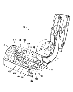
[0015] Turning now to FIG. 3, a close-up perspective view of a vacuum cleaner
10 having one
embodiment of an illumination system 102 consistent with the present
disclosure is generally
illustrated. As used herein, the term vacuum cleaner 10 is intended to refer
to any type of
vacuum cleaner including, but not limited to, hand-held vacuum cleaners 100
and robot vacuum
cleaners 200. As such, while the illumination system 102 is shown in
combination with a
surface treatment head 112 of a hand-held vacuum cleaner 100, it should be
appreciated that
the illumination system 102 may also be included in any vacuum cleaner
including, but not
limited to, a robot vacuum cleaner 200.
[0016] The vacuum cleaner 10 includes a vacuum body or housing 120 defining at
least one
air inlet 118. In the illustrated embodiment, the air inlet 118 is formed on a
bottom surface 302
of the vacuum housing 120. One or more agitators 114 are at least partially
disposed within
the vacuum housing 120, for example, within an agitator chamber 304 at least
partially formed
by the vacuum housing 120. A portion of the agitator 114 may extend beyond the
air inlet 118
and may be configured to contact a surface to be cleaned (e.g. a floor and/or
carpet). One or
more motors 306 may be directly or indirectly coupled (e.g., using a
drivetrain 308 such as
gears, belts, or the like) to the agitator 114 to rotate the agitator 114
within the air inlet 118
about a pivot axis PA in any manner known to those skilled in the art. The
agitator 114 may
include an agitator body 310 and one or more agitating features 312 such as,
but not limited to,
bristles (e.g., continuous and/or discontinuous rows of bristles and/or tufts
of bristles), felt,
flexible strips (e.g., rubber strips or the like), flexible and/or rigid
sidewalls, and/or the like).
The agitator body 310 may be referred to as an elongated agitator body 310
because the length
of the agitator body 310 along the pivot axis PA may be greater than the width
or height (e.g.,
the diameter) of the agitator body 310. For example, the length of the
agitator body 310 along
the pivot axis PA may be at least twice the width or height (e.g., the
diameter) of the agitator
body 310, or for example, at least four times the width or height (e.g., the
diameter) of the
agitator body 310.
[0017] With reference to FIG. 4, a cross-sectional view of the agitator body
310 of FIG. 3 is
generally illustrated. The agitator body 310 may include one or more
illumination chambers
4
CA 03114587 2021-03-26
WO 2020/072567
PCMJS2019/054176
402 configured to receive at least a portion of one or more illumination
systems 102. The
illumination chambers 402 may extend along all or a portion of the elongated
agitator body
310. For example, one or more of the illumination chambers 402 extend from a
first opening
disposed proximate a first end of the elongated agitator body 310 to a second,
oppositely
disposed opening disposed proximate a second, opposite end of the elongated
agitator body
310. Alternatively (or in addition), one or more of the illumination chambers
402 may be
disposed within a central region of the elongated agitator body 310 (i.e.,
which is not open to
the first and second ends) and/or may extend from one of the ends partially
towards the other
end of the elongated agitator body 310.
[0018] The illumination chambers 402 may be configured to receive at least a
portion of the
illumination system 102. For example, the illumination system 102 may include
one or more
light sources 404 coupled to a support surface 406. According to one
embodiment, the light
sources 404 may include one or more light emitting diodes (LEDs); however, it
should be
appreciated that the light sources 404 may include any light source known to
those skilled in
the art. According to one embodiment, one or more of the light sources 404 may
be configure
to emit light in the visible light spectrum. For example, one or more of the
light sources 404
may be configured to emit white light (i.e., containing a combination of light
in having
wavelengths from about 400 nm to about 700 nm). The white light may be used to
illuminate
an area proximate to the vacuum cleaner 10. Alternatively (or in addition),
one or more of the
light sources 404 may be configured to emit light having another color such
as, but not limited
to, red, yellow, blue, green, orange, and the like. The light sources 404 may
be configured to
emit light in specific wavelength ranges and/or patterns to convey information
to a user. For
example, the light sources 404 may emit light within one or more specific
wavelength ranges
and/or patterns to convey information about one or more parameters of the
vacuum cleaner 10
including, but not limited to, battery life, suction power, status of the
filters 106, remaining
capacity of the debris compartment 104, amount of debris being picked up
(i.e., how dirty the
surface is being vacuumed), remaining runtime, operating time (i.e., how long
the vacuum
cleaner has been operating), error and mode communication, or the like.
Alternatively (or in
addition), the light sources 404 may be adjustable by the user to emit light
in different
wavelength ranges.
[0019] According to one embodiment, one or more of the light sources 404 may
be configure
to emit light in the infrared (IR) light spectrum (i.e., light with a
wavelength from about 700
nm to 1 mm.) For example, the IR light emitted by the light sources 404 may be
used for
navigational purposes, for example, to detect obstacles in a room.
CA 03114587 2021-03-26
WO 2020/072567
PCMJS2019/054176
[0020] According to another embodiment, one or more of the light sources 404
may be
configured to emit light in the ultraviolet (UV) light spectrum (i.e., light
with
a wavelength from 10 nm to 400 nm). For example, the UV light emitted by the
light sources
404 may be used to disinfectant for the vacuum cleaner 10. The UV light may
therefore reduce
bacteria and/or mold growth on vacuum cleaner 10, for example, on the agitator
114 and/or
within the agitator chamber 118. Alternatively (or in addition), the UV light
emitted by the
light sources 40 may be configured to be absorbed by debris on the agitator
114 (e.g., debris
such as hair and/or fur wrapped around the agitator 114). The UV light may
break-down the
hair and/or fur. For example, the UV light may disrupt protein bonds within
the hair and/or
fur, thereby causing the hair/fur to more easily break into smaller
pieces/segments that can be
removed from the agitator 114 and collected in the debris compartment 104. The
agitator 114
and/or the vacuum housing 120 may optionally be formed from a UV resistant
material. For
example, the agitator 114 and/or the vacuum housing 120 may be formed from a
UV resistant
plastic and/or from a material having one or more UV resistant coatings/layers
and/or UV
stabilizers. Non-limiting examples of UV resistant plastic materials include
acrylic,
polyetherimide (PEI), polyvinylidene fluoride (PVDF), and
polytetrafluoroethylenez (PTFE).
[0021] One or more of the light sources 404 may be energized when the vacuum
cleaner 10 is
powered (i.e., when the vacuum cleaner 10 is operating to remove debris from a
surface). For
example, one or more of the light sources 404 may be energized whenever the
vacuum cleaner
is powered and/or one or more of the light sources 404 may be selectively
energized.
Alternatively (or in addition), one or more of the light sources 404 may be
energized when the
vacuum cleaner 10 is off (i.e., when the vacuum cleaner 10 is not operating to
remove debris
from a surface).
[0022] According to one embodiment, the light sources 404 may be energized
when the
vacuum cleaner 10 is placed on and/or in (e.g., coupled to) a storage dock.
Some or all of the
light sources 404 may be configured to emit light (e.g., but not limited to,
UV light) which is
contained substantially entirely within the vacuum cleaner 10 (e.g., the UV
light emitted by the
light sources 404 is generally not visible to a user). Such an embodiment may
allow the light
sources 404 to emit light over a longer period of time (thus enhancing the
ability of the light
source 404 to break-down debris wrapped around the agitator 114). As noted
above, the light
sources 404 may be coupled to one or more support surfaces 406. According to
one
embodiment, the support surface 406 may include a printed circuit board (PCB).
The PCB
may include any necessary circuitry such as, but not limited to, power
conditioners, voltage
6
CA 03114587 2021-03-26
WO 2020/072567
PCMJS2019/054176
regulators, sensors, or the like. Alternatively, the support surface 406 may
include any
mounting surface to which the light sources 404 may be secured.
[0023] According to one embodiment, the illumination system 102 is
stationarily disposed
within the illumination chamber 402 (i.e., the illumination system 102 does
not move relative
to the vacuum housing 120 and the agitator 114 rotates around the illumination
system 102)
about pivot axis PA. The agitator body 310 may be formed from a transparent
and/or semi-
transparent material that allows at least some of the light emitted by the
light sources 404 (such
as, but not limited to, visible light, UV light, and/or IR light) disposed
within the illumination
chamber 402 to pass through the agitator body 310. Optionally, one or more of
the agitating
features 312 may be formed from a transparent and/or semi-transparent material
that allows at
least some of the light emitted by the light sources 404 disposed within the
illumination
chamber 402 to pass through the agitating features 312. According to one
embodiment, a least
a portion of the body 120 may be formed from a transparent and/or semi-
transparent material
that allows at least some of the light emitted by the light sources 404
disposed within the
illumination chamber 402 to pass through the body 120. For example, the body
120 may
include a transparent and/or semi-transparent cover or lid 408 that extends
over (and optionally
partially defines) the agitator chamber 118. The cover/lid 408 may function as
a window that
allows a user to see at least partially into the agitator chamber 118 and
through which at least
a portion of the agitator 114 and the illumination system 102 may be visible
from the exterior
while the vacuum cleaner 10 is in normal use (i.e., while cleaning a floor).
As used herein, a
material is considered transparent if at least 90% of the light which
intersects with the material
passes through the material, and a material is considered semi-transparent if
at least 30% of the
light which intersects with the material passes through the material.
[0024] Optionally, one or more seals 410 (e.g., but not limited to, 0-rings or
the like) may be
provided to seal at least a portion of the illumination chamber 402 (e.g., the
portion which
includes the light sources 404) from debris in the agitation chamber 118. For
example, one or
more seals 410 may be disposed proximate each end of the illumination chamber
402.
[0025] According to another embodiment, the illumination system 102 may be
configured to
rotate with the agitator 114. The light sources 404 may be coupled directly to
the agitator body
310 and/or may be secured within one or more illumination chambers 402 formed
within the
agitator body 310. The light sources 402 may include a power source that is
separate from the
rest of the vacuum cleaner 10. For example, the light sources 404 may include
separate
batteries and/or may be powered by a magnetic induction system in which
rotation of the
agitator 114 may induce a current used to power the light sources 404.
Alternatively, one or
7
CA 03114587 2021-03-26
WO 2020/072567
PCMJS2019/054176
more rotatable electrical connections may be provided between the agitator 114
and the vacuum
housing 120 to provide electricity to the light sources 404.
[0026] Turning now to FIG. 5, one example of vacuum cleaner 10 including
another
embodiment of an illumination system 102 consistent with the present
disclosure is generally
illustrated. As noted previously, while the illumination system 102 is shown
in combination
with a surface treatment head 112 of a hand-held vacuum cleaner 100, it should
be appreciated
that the illumination system 102 may also be included in any vacuum cleaner
including, but
not limited to, a robot vacuum cleaner 200.
[0027] The illumination system 102 includes one or more light sources 404 and
one or more
waveguides, light guides, and/or light tubes 502. The light sources 404 may
include any light
source known to those skilled in the art including, but not limited to, one or
more LEDs. The
light sources 404 may be configured to emit light generally in the direction
of the waveguide,
light guide, and/or light tubes 502. The waveguides, light guides, and/or
light tubes 502 may
include one or more light receiving surfaces and one or more light emitting
surfaces.
Optionally, the waveguide, light guide, and/or light tube 502 may include one
or more lenses,
diffusers, or the like to configured to emit light in a desired illumination
pattern. One such
illumination pattern includes illuminating an area in proximate to and in
front of the vacuum
cleaner 10 (e.g., in front of and proximate to the surface treatment head 112
and/or the body
120).
[0028] The waveguide, light guide and/or light tube 502 may configured to
guide the light
passing therethrough from a first direction (i.e., the direction emitted from
the light source 404)
to a second, different direction (e.g., the desired illumination pattern). One
example of a
waveguide, light guide and/or light tube 502 may include a structure which
utilizes total
internal refraction. Some of the light emitted from the light sources 404 may
be used to
illuminate areas to the left and/or right of the vacuum cleaner 10 and/or in
front of (and/or
behind) the vacuum cleaner 10). According to one embodiment, the waveguide,
light guide
and/or light tube 502 may include at least an upper surface through which
substantially no light
passes through (i.e., less than 10% of light passes through). Preventing light
from being emitted
through this upper surface may generally prevent the light being emitted
directly towards the
user which could cause undesired glare.
[0029] The light guide 502 may be configured to receive at least a portion of
the light emitted
by one or more light sources 404. The light sources 404 may be mounted
anywhere on the
vacuum cleaner 10. For example, the light sources 404 may be disposed within
the agitation
chamber 304, within the illumination chamber 402, and/or external to the
agitation chamber
8
CA 03114587 2021-03-26
WO 2020/072567
PCMJS2019/054176
304 and the illumination chamber 402 (e.g., mounted on/in the vacuum housing
120).
According to one embodiment, the light guide 502 is formed by the transparent
agitator window
in the vacuum body 120. Alternatively (or in addition), the light guide 502 is
configured to
receive formed by the transparent agitator window in the vacuum body 120.
[0030] Turning back to FIGS. 1 and 2, the vacuum cleaner 10 may include one or
more debris
sensors 169. The debris sensor 169 may be configured to generate a signal
based on the amount
of debris within and/or proximate to the agitator chamber agitator chamber
304. The light
sources 404 of the illumination system 102 may be configured to change colors
based on the
amount of debris detected by the debris sensor 169.
[0031] While the principles of the invention have been described herein, it is
to be understood
by those skilled in the art that this description is made only by way of
example and not as a
limitation as to the scope of the invention. Other embodiments are
contemplated within the
scope of the present invention in addition to the exemplary embodiments shown
and described
herein. Modifications and substitutions by one of ordinary skill in the art
are considered to be
within the scope of the present invention, which is not to be limited except
by the following
claims.
9