Note: Descriptions are shown in the official language in which they were submitted.
CA 03114748 2021-03-29
WO 2020/072204 PCT/US2019/051850
PINCH CLAMP
BACKGROUND
[0001] Pinch clamps are commonly employed to obstruct tubing of an
intravenous or other
medical system. Pinch clamps oftentimes have a clam-shell design where an
upper arm is
connected to a lower arm via a living hinge. The lower arm is typically
configured to retain the
upper arm in a closed position in which the tubing is clamped between the two
arms.
[0002] Traditional pinch clamp designs suffer from various drawbacks. For
example, due to
the molding process, pinch clamps typically have sharp edges that may cause
patient discomfort.
The molding process also causes the pinch clamps to be relatively bulky. Many
pinch clamp
designs also allow the two arms to move laterally when in the closed position
leading to unintended
disengagement of the pinch clamp. Even when lateral disengagement features are
incorporated
into these designs, asymmetry in the features oftentimes leads to failure in
one direction.
[0003] Many pinch clamp designs also enable over-engagement which may
result in rebound.
Figures 1A-1C illustrate an example of how rebound may occur when a pinch
clamp 100 is over-
engaged. Pinch clamp 100 includes an upper arm 110 that is connected to a
lower arm 120 via a
living hinge 130. A terminal portion 140 (where "terminal" represents that
terminal portion 140
is towards the patient or distal end of tubing 190 relative to living hinge
130) extends upwardly
from lower arm 120 opposite living hinge 130. An engaging structure 141 is
formed at the upper
end of terminal portion 140. Engaging structure 141 forms an engaging surface
141 that is oriented
downwardly to enable the leading end 111 of upper arm 110 to be maintained
below engaging
surface 141 to thereby engage pinch clamp 100. In this engaged position, lower
clamping surface
-1-
CA 03114748 2021-03-29
WO 2020/072204 PCT/US2019/051850
151 and upper clamping surface 152 are positioned with sufficient proximity to
obstruct tubing
190 that extends through pinch clamp 100.
[0004] Figure 1A illustrates pinch clamp 100 when in the engaged position.
To move pinch
clamp 100 into this engaged position, the clinician will typically squeeze
upper and lower arms
110, 120 until leading end 111 of upper arm 110 drops below engaging surface
141. At that point,
the biased terminal portion 140 will maintain leading end 111 beneath engaging
surface 141.
Difficulties arise, however, due to the ability of upper arm 110 to travel
downwardly beyond what
is necessary to reach the engaged position. For example, Figure 1B illustrates
that upper arm 110
has been forced downward so that leading end 111 has traveled substantially
beyond engaging
surface 141a. As a result, upper clamping surface 152 has contacted lower
clamping surface 151
and traveled in a forward direction (i.e., towards terminal end 140) relative
to lower clamping
surface 151.
[0005] This forward movement of upper clamping surface 152 relative to
lower clamping
surface 151 results in "positive displacement" of the fluid within tubing 190
as represented by the
arrow in Figure 1B. In other words, the over-engagement of pinch clamp 100
will cause fluid
within tubing 190 to flow into or at least towards the patient. Positive
displacement is generally
desirable. However, in this scenario, because the positive displacement is a
result of over-
engagement, a rebound will occur as represented in Figure 1C. In Figure 1C, it
is assumed that
the clinician is no longer squeezing pinch clamp 100 and therefore, upper arm
110 has pivoted
upwardly back to the engaged position (i.e., until leading end 111 contacts
engaging surface 141a).
This upward movement of upper arm 110 relative to lower arm 120 will cause
upper clamping
surface 152 to also travel in an upward and somewhat backward direction. This
upward and
backward movement increases the internal volume of tubing 190 downstream from
the "pinch
-2-
CA 03114748 2021-03-29
WO 2020/072204 PCT/US2019/051850
point." (i.e., the point where lower clamping surface 151 and upper clamping
surface 152 occlude
tubing 190). As a result, fluid ¨ likely including blood ¨ will be sucked into
the catheter of other
device to which tubing 190 is coupled. The term rebound represents this
transition from the over-
engaged position depicted in Figure 1B to the engaged position depicted in
Figure 1C.
[0006] The reflux that results from a pinch clamp rebound creates a number
of problems. For
example, the reflux of blood can increase the risk of occlusion (e.g., due to
an intraluminal
thrombus within the catheter) which may prevent fluids from being infused
through the catheter
or prevent blood from being withdrawn. Even if occlusion does not occur, the
reflux can increase
the risk of infection.
SUMMARY
[0007] The present disclosure relates generally to pinch clamps that are
designed to provide
positive displacement while also preventing rebound. As a result, the design
of these pinch clamps
minimizes the occurrence of reflux. In addition to preventing rebound, the
design of the pinch
clamps can prevent lateral disengagement, minimize the force required for
engagement and
enhance patient comfort.
[0008] To prevent rebound while providing positive displacement, the upper
and lower
clamping surfaces may be configured to form a pinch profile along which the
tubing is compressed
with the pinch point being formed at the distal end of the pinch profile. To
further prevent rebound,
the lower arm of the pinch clamp can include blocking ribs that interface with
the upper clamping
surface to prevent distal travelling of the pinch point even if the upper arm
is forced into an over-
engaged position.
-3-
CA 03114748 2021-03-29
WO 2020/072204 PCT/US2019/051850
[0009] In some embodiments, the present invention is implemented as a pinch
clamp that
includes an upper arm having a proximal end and a distal end and a lower arm
having a proximal
end and a distal end where the proximal end of the lower arm is coupled to the
proximal end of the
upper arm via a hinge. The pinch clamp also includes a terminal end that
extends upwardly from
the distal end of the lower arm. The terminal end includes an engaging
structure that forms an
engaging surface that interfaces with the distal end of the upper arm to
retain the pinch clamp in
an engaged position. An upper clamping surface is formed on the upper arm and
has a proximal
portion and a distal portion. Also, a lower clamping surface is formed on the
lower arm and has a
proximal portion and a distal portion. When the pinch clamp is in the engaged
position, a distance
between the distal portion of the upper clamping surface and the distal
portion of the lower
clamping surface is less than a distance between the proximal portion of the
upper clamping
surface and the proximal portion of the lower clamping surface.
[0010] In other embodiments, the present invention is implemented as a
pinch clamp that
includes an upper arm having a proximal end and a distal end and a lower arm
having a proximal
end and a distal end where the proximal end of the lower arm is coupled to the
proximal end of the
upper arm via a hinge. The pinch clamp also includes a terminal end that
extends upwardly from
the distal end of the lower arm. The terminal end includes an engaging
structure that forms an
engaging surface that interfaces with the distal end of the upper arm to
retain the pinch clamp in
an engaged position. An upper clamping surface is formed on the upper arm and
has a proximal
portion and a distal portion. Also, a lower clamping surface is formed on the
lower arm and has a
proximal portion and a distal portion. The pinch clamp further includes
blocking ribs that are
positioned on opposing sides of the lower arm and extend distally from the
distal portion of the
lower clamping surface.
-4-
CA 03114748 2021-03-29
WO 2020/072204 PCT/US2019/051850
[0011] In other embodiments, the present invention is implemented as a
pinch clamp that
includes an upper arm having a proximal end and a distal end and a lower arm
having a proximal
end and a distal end where the proximal end of the lower arm is coupled to the
proximal end of the
upper arm via a hinge. The pinch clamp also includes a terminal end that
extends upwardly from
the distal end of the lower arm. The terminal end includes an engaging
structure that forms an
engaging surface that interfaces with the distal end of the upper arm to
retain the pinch clamp in
an engaged position. An upper clamping surface is formed on the upper arm and
has a flat
proximal portion and a distal portion that protrudes downwardly from the flat
proximal portion. A
lower clamping surface is formed on the lower arm and is flat.
[0012] It is to be understood that both the foregoing general description
and the following
detailed description are exemplary and explanatory and are not restrictive of
the invention, as
claimed. It should be understood that the various embodiments are not limited
to the arrangements
and instrumentality shown in the drawings. It should also be understood that
the embodiments may
be combined, or that other embodiments may be utilized and that structural
changes, unless so
claimed, may be made without departing from the scope of the various
embodiments of the present
invention. The following detailed description is, therefore, not to be taken
in a limiting sense.
BRIEF DESCRIPTION OF THE SEVERAL VIEWS OF THE DRAWINGS
[0013] Example embodiments will be described and explained with additional
specificity and
detail through the use of the accompanying drawings in which:
[0014] Figures 1A-1C illustrate a prior art pinch clamp including how the
pinch clamp causes
reflux when the pinch clamp is over-engaged;
-5-
CA 03114748 2021-03-29
WO 2020/072204 PCT/US2019/051850
[0015] Figure 2A provides a front perspective view of a pinch clamp
configured in accordance
with embodiments of the present invention;
[0016] Figure 2B provides a front view of the pinch clamp of Figure 2A;
[0017] Figure 2C provides a side view of the pinch clamp of Figure 2A;
[0018] Figure 2D provides a cross-sectional front view of the pinch clamp
of Figure 2A when
in the disengaged position;
[0019] Figure 2E provides a cross-sectional front view of the pinch clamp
of Figure 2A when
in the engaged position;
[0020] Figure 3 illustrates a pinch clamp configured in accordance with
another embodiment
of the present invention;
[0021] Figure 4 illustrates a pinch clamp configured in accordance with
another embodiment
of the present invention; and
[0022] Figure 5 illustrates a pinch clamp configured in accordance with
another embodiment
of the present invention.
DESCRIPTION OF EMBODIMENTS
[0023] Pinch clamps that are configured in accordance with the present
invention can provide
positive displacement while also preventing rebound to thereby minimize the
occurrence of reflux.
By structuring the upper and lower clamping surfaces to provide a pinch
profile, as opposed to a
single pinch point, the pinch clamps of the present invention can cause
positive displacement.
Additionally, the upper and lower clamping surfaces can be configured to form
the pinch point
towards the distal end of the pinch profile. The positioning of the pinch
point towards the distal
end can minimize the likelihood of rebound if the pinch clamp is over-engaged.
Alternatively or
additionally, the pinch clamps can include blocking ribs that interface with
the upper clamping
-6-
CA 03114748 2021-03-29
WO 2020/072204 PCT/US2019/051850
surface to prevent distal travelling of the pinch point even if the upper arm
is forced into an over-
engaged position
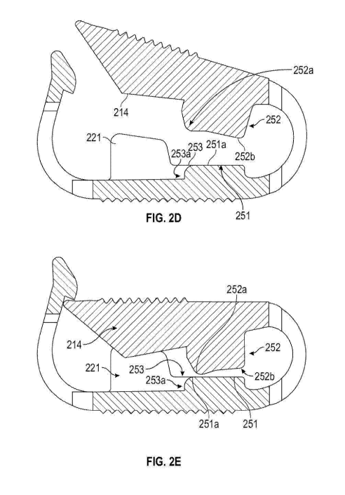
[0024] Figures 2A-2E provide various views of a pinch clamp 200 that is
configured in
accordance with embodiments of the present invention. Pinch clamp 200 includes
an upper arm
210, a lower arm 220, a living hinge 230 that couples the proximal ends of
upper and lower arms
210, 220 and a terminal end 240 that extends upwardly from the distal end of
lower arm 220.
Living hinge 230 and terminal end 240 form openings 230a and 240a respectively
through which
tubing (not shown) extends. An upper portion of terminal end 240 forms an
engaging structure
241 having a downward facing engaging surface 241a. Upper arm 210 pivots
relative to lower
arm 220 to allow leading end 211 of upper arm 210 to be secured under engaging
surface 241a to
thereby maintain pinch clamp 200 in the engaged position. In some embodiments,
leading end
211 may include a protruding portion 212 that extends outwardly from one side
of upper arm 210.
To enhance grip, upper arm 210 and lower arm 220 may include a series of
ridges 213 and 222
respectively that span the width of the respective arm.
[0025] To prevent lateral disengagement, lower arm 220 can include tabs 221
that extend
upwardly from opposing sides of lower arm 220 to thereby form a gap between
the tabs. Upper
arm 210 can include a rib 214 that extends downwardly from the underside of
upper arm 210 and
that is configured to insert into the gap between tabs 221. The interface
between rib 214 and tabs
221 will prevent upper arm 210 from moving laterally relative to lower arm 220
while in the
engaged position thereby preventing leading end 211 from becoming laterally
disengaged from
engaging surface 241a. As is best seen in Figure 2B, rib 214 and tabs 221 can
be positioned
towards terminal end 240. In addition to preventing lateral disengagement,
tabs 221 also function
to center the tubing between lower arm 210 and upper arm 220. In other
embodiments, pinch
-7-
CA 03114748 2021-03-29
WO 2020/072204 PCT/US2019/051850
clamp 200 may not include rib 214 as is shown in Figure 5. In such
embodiments, pinch clamp
200 can be disengaged by lateral movement but will still provide positive
displacement and center
the tubing.
[0026] As is best shown in Figure 2B, pinch clamp 200 can be configured so
that, when lower
arm 220 is horizontal and pinch clamp 220 is in the disengaged position, upper
arm 210 will be
oriented at an upward angle. Also, as best shown in Figure 2C, the outer edges
231 of upper arm
210 and lower arm 220 are rounded to eliminate sharp edges and thereby enhance
patient comfort.
[0027] Upper arm 210 forms an upper clamping surface 252 that is positioned
proximal to and
extends downwardly beyond rib 214. In some embodiments, including the
embodiment depicted
in Figures 2A-2E, upper clamping surface 252 includes a generally flat
proximal portion 252b and
a protruding distal portion 252a. In other embodiments, upper clamping surface
252 may not
include protruding distal portion 252a such that upper clamping surface 252 is
generally flat from
its proximal end to its distal end. Lower arm 220 forms a lower clamping
surface 251 that is
generally flat. Blocking ribs 253 extend distally beyond a distal end of lower
clamping surface
251 along opposing sides of lower arm 220. A gap 253a is thereby formed
between blocking ribs
253 distal to lower clamping surface 251. In some embodiments, tabs 221
comprise a raised
extension of blocking ribs 253.
[0028] Upper clamping surface 252 and lower clamping surface 251 are both
elongated to
thereby create a pinch profile when pinch clamp 200 is in the engaged
position. With reference to
Figures 2D and 2E, upper clamping surface 252 can be configured so that it is
angled upwardly in
a distal direction relative to lower clamping surface 251 when pinch clamp is
in the disengaged
position. Then, once pinch clamp 200 is transitioned into the engaged
position, upper clamping
surface 252 pivots into a downward orientation relative to lower clamping
surface 251. As part of
-8-
CA 03114748 2021-03-29
WO 2020/072204 PCT/US2019/051850
this transition, proximal portion 252b will first contact and compress the
tubing towards a proximal
end of lower clamping surface 251. This compression of the tubing will cause
positive
displacement. As pinch clamp 200 transitions fully into the engaged position
and due to the
downwardly angled orientation of upper clamping surface 252, distal portion
252a will contact,
compress and occlude the tubing (i.e., create the pinch point) towards a
distal end of lower
clamping surface 251. Accordingly, the pinch profile consists of compression
of the tubing
towards the proximal end of clamping surfaces 251/252 and occlusion of the
tubing at the distal
end of clamping surfaces 251/252.
[0029] The force required to occlude the tubing is minimized by providing
protruding distal
portion 252a. More specifically, protruding distal portion 252a minimizes the
length of the tubing
that is occluded thereby minimizing the squeezing force required to reach the
engaged position.
In contrast, if upper clamping surface 252 is flat, a greater length of tubing
would be compressed
and occluded thereby increasing the squeezing force required to reach the
engaged position.
[0030] Again with reference to Figure 2E, due to the positioning of
blocking ribs 253, if an
over-engaging force is applied to pinch clamp 200, upper clamping surface 252
will be blocked
from travelling in a downward direction relative to lower clamping surface
251. In other words,
blocking ribs 253 will prevent the pinch point from travelling in a distal
direction thereby
preventing rebound once the over-engaging force is removed. The generally flat
orientation of
lower clamping surface 251 and blocking ribs 253 combined with the downwardly
angled
orientation of upper clamping surface 252 will also convert the over-engaging
force on upper arm
220 into a pivoting force around distal portion 252a. This pivoting force will
minimize the
likelihood that upper clamping surface 252 will slide in a distal direction
relative to lower clamping
surface 251.
-9-
CA 03114748 2021-03-29
WO 2020/072204 PCT/US2019/051850
[0031] Figure 3 illustrates an alternate configuration of lower clamping
surface 251 and upper
clamping surface 252 that also provides a pinch profile. In this embodiment,
upper clamping
surface 252 includes a generally flat proximal portion 252b and a protruding
distal portion 252a
similar to what was described above. However, lower clamping surface 251 also
includes a
protruding distal portion 25 lb that generally aligns with distal portion 252a
but that is elongated
relative to distal portion 252a. In this configuration, the generally flat
proximal portions of upper
and lower clamping surfaces 252/251 will compress the tubing while distal
portions 252a/251a
will form the pinch point.
[0032] Figure 4 illustrates another alternate configuration of lower
clamping surface 251 and
upper clamping surface 252 that also provides a pinch profile. In this
embodiment, lower clamping
surface 251 is not flat, but includes a protruding proximal portion 25 lb in
addition to protruding
distal portion 251a. Proximal portion 251b protrudes upwardly farther than
distal portion 251a.
Upper clamping surface 252 includes protruding distal portion 252a as well as
a protruding
proximal portion 252b. A recessed portion 252c is formed between distal
portion 252a and
proximal portion 252b and has a curved shape that corresponds to the curved
shape of proximal
portion 25 lb. Proximal portion 25 lb inserts into recessed portion 252c which
in turn can prevent
over-engagement of the pinch clamp.
[0033] As shown in Figure 4, when in the engaged position, a generally
constant spacing is
formed between proximal portion 251b and recessed portion 252c and between
proximal portion
25 lb and proximal portion 252b. This constant spacing forms a channel in
which the tubing will
be compressed but not occluded. In contrast, in the engaged position, the
spacing between distal
portion 252a and distal portion 251a is less than the constant spacing between
the other portions
so that a pinch point is formed between distal portions 252a/251a.
-10-
CA 03114748 2021-03-29
WO 2020/072204 PCT/US2019/051850
[0034] In the embodiments shown in Figures 3 and 4, the elongated upper and
lower clamping
surfaces will provide positive displacement and will also prevent rebound.
Rebound is prevented
due to the pinch profile which positions the pinch point at the distal end of
the clamping surfaces.
[0035] In summary, the pinch clamps of the present invention include upper
and lower
clamping surfaces that are configured to provide a pinch profile. This pinch
profile provides
positive displacement by compressing the tubing towards the proximal end of
the clamping
surfaces and prevents rebound by positioning the pinch point towards the
distal end of the clamping
surfaces.
-11-