Note: Descriptions are shown in the official language in which they were submitted.
CA 03115229 2021-04-01
WO 2020/072410
PCT/US2019/053946
- 1 -
TITLE
IMPACT ATTENUATION STRUCTURE
CROSS-REFERENCE TO RELATED APPLICATION
[0001] This application claims the benefit of U.S. Provisional Application No.
62/740,666, filed October 3, 2018.
BACKGROUND OF THE INVENTION
Field of the Invention
[0002] This invention relates to vehicle systems for absorbing impact energy.
Description of the Related Art
[0003] Structures, sometimes referred to as crash boxes, are utilized in the
automotive field to lessen the severity of collisions. These structures are
designed to collapse upon impact and thereby absorb impact energy, both to
reduce vehicle speed more safely and to lower damage to vehicle components.
CA 03115229 2021-04-01
WO 2020/072410
PCT/US2019/053946
- 2 -
SUMMARY OF THE INVENTION
[0004] The present invention provides an impact structure intended to
attenuate
the severity of undesired forceful contact with other vehicles, fixed objects
and
the like.
[0005] In one aspect, the invention is directed to an impact structure for
attenuating longitudinally-directed vehicle impacts comprising first and
second
attenuation plates, where the plates are spaced apart from each other at a
mounting region of the impact structure and fixed to each other at an impact
region of the impact structure, and where the impact region is longitudinally
distal from the mounting region. There is an aperture pattern on each
attenuation
plate, where each aperture of the aperture pattern on each attenuation plate
has an
aspect ratio defined by the maximum size of the aperture in the longitudinal
direction divided by the maximum size of the aperture in a direction
approximately perpendicular to the longitudinal direction; and the aspect
ratio of
the apertures of the aperture pattern on each attenuation plate generally
increases
or decreases in the longitudinal direction between the mounting region and the
impact region.
[0006] In another aspect, the invention is directed to an impact structure for
attenuating longitudinally-directed vehicle impacts comprising first and
second
attenuation plates, where the plates are spaced apart from each other at a
mounting region of the impact structure and fixed to each other at an impact
region of the impact structure, and the impact region is longitudinally distal
from
the mounting region. There is an aperture pattern on each attenuation plate,
where the apertures of the aperture pattern on each aperture plate have an
increasing or decreasing aperture area in the longitudinal direction between
the
mounting region and the impact region, so that the amount of plate material
changes in the longitudinal direction between the mounting region and the
impact
region.
CA 03115229 2021-04-01
WO 2020/072410
PCT/US2019/053946
- 3 -
[0007] These and other aspects of the present invention are described in the
drawings annexed hereto, and in the description of the embodiments and claims
set forth below.
BRIEF DESCRIPTION OF THE DRAWINGS
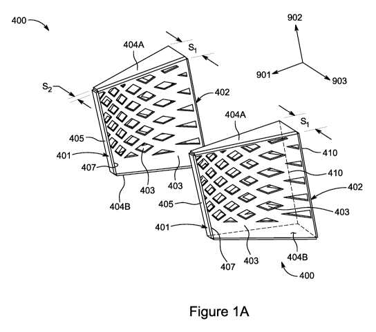
[0008] Figure 1A is a perspective view of a pair of impact structures in
accordance with one embodiment of the present invention, and Figure 1B depicts
a perspective view of the pair of impact structures depicted in Figure 1A
positioned at appropriate locations on the front of a chassis of a vehicle.
[0009] Figure 2A is a perspective view of a pair of impact structures in
accordance with a second embodiment of the present invention, and Figure 2B
depicts a perspective view of one of the pair of impact structures depicted in
Figure 2A positioned at an appropriate location on the rear of a chassis of a
vehicle.
[0010] Figure 3A is a plan view of an attenuation plate in accordance with one
embodiment of the present invention, and Figure 3B is the same plan view
illustrating certain geometrical relationships relating to the apertures in
the
attenuation plate.
[0011] Figure 4 is a plan view of an attenuation plate in accordance with the
second embodiment of the present invention.
DETAILED DESCRIPTION OF THE PREFERRED EMBODIMENTS
[0012] Figure 1A depicts one embodiment of the present invention, impact
structure 400. For convenience of reference, the "longitudinal" direction is
denoted by arrow 901, the "vertical" direction is denoted by arrow 902, and
the
"transverse" direction is denoted by arrow 903, which arrows are shown in
Figure
1A and elsewhere. For clarity, the vehicle on which impact structure 400 is
mounted, vehicle 10 (a portion of which is seen in Figure 1B) rolls (on a
straight
road) in the longitudinal direction; i.e., in the direction indicated by arrow
901.
CA 03115229 2021-04-01
WO 2020/072410
PCT/US2019/053946
- 4 -
[0013] Also for convenience of reference, reference in this disclosure to the
"forward" portion of a structure or component, and like references, refers to
the
portions of the structure or component positioned toward the head of the arrow
901, and correspondingly, reference herein to the "rearward" portion of a
structure or component, and like references, refers to the portions of the
structure
or component positioned away from the head of the arrow 901. Likewise for
convenience of reference, reference in this disclosure to the "top" portion of
a
structure or component, and like references, refers to the portions of the
structure
or component positioned toward the head of the arrow 902, and correspondingly,
reference herein to the "bottom" portion of a structure or component, and like
references, refers to the portions of the structure or component positioned
away
from the head of the arrow 902.
[0014] Still further for convenience of reference, the "length" of impact
structure 400 generally refers to its dimension in the direction of arrow 901,
the
"width" of impact structure 400 generally refers to its dimension in the
direction
of arrow 902, and the "thickness" of impact structure 400 generally refers to
its
dimension in the direction of arrow 903. Among the different embodiments
disclosed herein, like numerical designators refer to the same components.
[0015] Impact structure 400 is adapted for mounting to the forward or rear
portion of a chassis 15 of vehicle 10. The front of vehicle 10 is shown for
example in Figure 1B. Generally two or more of structures 400 are to be
arranged across the front of a chassis 15; thus the two structures 400 shown
in
Figure 1A are depicted in Figure 1B affixed to the front of the chassis 15 of
a
vehicle 10. Chassis 15 is characterized by a number of tubular members
fastened
to each other and arranged to form a three dimensional exoskeleton structure,
sometimes referred to as a space frame. Although described with respect to the
particular structure of chassis 15 for illustrative purposes, impact structure
400
and the inventions described herein can be utilized with a variety of
different
chassis designs.
CA 03115229 2021-04-01
WO 2020/072410
PCT/US2019/053946
- 5 -
[0016] In Figure IA, each impact structure 400 has two regions, impact region
401 and mounting region 402, and two principal operative components, namely
two attenuation plates 403, which are positioned between and join impact
region
401 and mounting region 402. In the embodiment shown, the attenuation plates
403 of each impact structure 400 are inclined toward each other in the
longitudinal direction from mounting region 402 to impact region 401, and the
rear edges 410 of the attenuation plates 403 of each impact structure 400 are
generally parallel.
[0017] Figure 3A depicts an attenuation plate 403 in plan view. Attenuation
plate 403 is a quadrilateral defined by forward edge 407, rear edge 410
(opposing
forward edge 407), top edge 408 and bottom edge 409 (opposing top edge 408).
Forward edge 407 and rear edge 410 are vertically oriented, and top edge 408
and
bottom edge 409 are longitudinally oriented. In this disclosure, a direction
is
considered to be in the "vertical direction," and a component is considered to
be
"vertically oriented," if the direction or component is oriented within 45
degrees
of the direction of arrow 902, and includes directions and orientations
exactly
oriented in the direction of arrow 902 as well as approximately oriented in
the
direction of arrow 902. Likewise in this disclosure, a direction is considered
to
be in the "longitudinal direction," and a component is considered to be
"longitudinally oriented," if the direction or component is oriented within 45
degrees of arrow 901, and includes directions and orientations exactly
oriented in
the direction of arrow 901 as well as approximately oriented in the direction
of
arrow 901.
[0018] In general, the shape and dimensions of attenuation plate 403 in plan
can
be varied to accommodate the dimensions of the vehicle structure to which
impact structure 400 is to be mounted, and/or to give impact structure 400 a
more
pleasing aesthetic, limited only by the desire not to significantly reduce the
amount of surface area of attenuation plate 403 from that which energy
absorption considerations may dictate, or the efficacy of that plate 403 to
absorb
impact energy, in the manner described below. For example, as shown in Figure
3A the length of forward edge 407 is less than the length of longitudinally
distal
CA 03115229 2021-04-01
WO 2020/072410
PCT/US2019/053946
- 6 -
opposing rear edge 410, whereas top and bottom edges 408, 409 have
approximately the same length. Further, the top edge 408 is shown in Figure 3A
as canted forward relative to bottom edge 409.
[0019] As shown in Figure 1A, the rear edges 410 of attenuation plates 403
proximate mounting region 402 are spaced apart a distance Si, and the edges of
attenuation plates 403 proximate impact region 401 are spaced apart a distance
52. In one embodiment, 52 is less than Si, so that impact structure 400, when
viewed from above, tapers in thickness from mounting region 402 to impact
region 401.
[0020] Attenuation plates 403 are joined by longitudinally oriented joinder
plates
404. In particular, the top opposed edges of attenuation plates 403 are joined
by
top joinder plate 404A, shown in Figure 1A, and the bottom opposed edges of
attenuation plates 403 are joined by bottom joinder plate 404B. The goal of
joinder plates 404 is to inhibit Euler-like buckling of plates 403 upon impact
of
impact structure 400, so that the collapse of plates 403 is maximally energy-
absorptive. One or more intermediate joinder plates 404C (not shown) may be
positioned between top joinder plate 404A and bottom joinder plate 404B as
desired to inhibit other higher order buckling modes.
[0021] The forward edges 407 of attenuation plates 403 are each fixed to the
other. Thus in the embodiment shown in Figure 1A, the forward edges 407 of
attenuation plates 403 proximate impact region 401 are joined by a nose strip
405, which is an elongate vertically oriented plate that separates those
forward
opposed edges by distance S2. The presence of nose strip 405 provides a narrow
surface that facilitates mounting a bumper or other fascia. Thus in the
embodiment of Figure 1A, impact structure 400 when viewed from above
appears as an isosceles trapezoid. In an alternative embodiment, the forward
edges 407 of attenuation plates 403 proximate impact region 401 are joined to
each other, such that distance S2 is approximately zero. In this embodiment,
impact structure 400 when viewed from above appears as an isosceles triangle.
CA 03115229 2021-04-01
WO 2020/072410
PCT/US2019/053946
- 7 -
[0022] Impact structure 400 is designed to offer progressively increasing
resistance to impact, and provide progressively increasing energy absorption,
as
an impact proceeds. That is, upon impact region 401 of impact structure 400
coming into contact with for example an object which significantly resists the
forward motion of vehicle 10, attenuation plates 403 at their forward edges
407
or rear edges 410 will begin to crumple (depending upon design), which absorbs
the kinetic energy of vehicle 10 and causes the rate of closure between the
object
and vehicle 10 to decrease. Additionally, the goal of the present invention is
for
crumpling not to occur longitudinally across attenuation plates 403 at the
same
time, but to start at the forward edges 407 or the rear edges 410 (depending
on
design) of attenuation plates 403, with the crumple front (the boundary
between
uncrumpled and crumpled portions of plates 403) moving in a longitudinal
direction between impact region 401 and mounting region 402. As it does so,
impact structure 400 offers progressively increasing amount of resistance to
impact, and absorbs progressively increasing amounts of energy. For example,
if
X is denominated the amount of energy absorbed in the collapse of the first
33%
of plates 403, then the amount of energy absorbed in the collapse of the next
33%
will not be X also, but Y, where Y is greater than X, with the value of Y
dependent upon the specific design of attenuation plates 403.
[0023] In one embodiment, impact structure 400 provides progressively
increasing resistance, and progressively increasing energy absorption, by
featuring a plurality of selectively shaped and/or positioned apertures 406 in
each
of attenuation plates 403, which in general results in there being changing
amounts of plate material in plates 403 in the longitudinal direction between
forward edges 407 of plates 403 and rear edges 410 of plates 403. In the
embodiment of attenuation plates 403 shown in Figures 3A and 3B, there is an
increasing amount of plate material in plates 403 in the longitudinal
direction
from forward edge 407 to rear edge 410. This characteristic is realized in the
embodiment of Figures 3A and 3B by providing a series of kite-shaped apertures
406 having a geometry as described herein.
CA 03115229 2021-04-01
WO 2020/072410
PCT/US2019/053946
- 8 -
[0024] In particular, referring to Figure 3A each kite-shaped aperture 406 is
defined by two interior vertical angles lAV and 2AV (a geometric line 411
joining the two interior vertical angles lAV and 2AV of each aperture 406 is
vertically oriented) and two interior longitudinal angles 1AL and 2AL (a
geometric line 412 joining the two interior angles 1AL and 2AL of each
aperture
406 is longitudinally oriented). Further, as shown in Figure 3B the apertures
406
are arranged in successive vertically oriented columns Cõ i in number. In
Figure
3B, there is depicted for illustration six columns, C1, C2, C3, C4, C5 and C6,
longitudinally arrayed across the face of an attenuation plate 403. The angles
1AVõ 2AV, of the apertures 406, of the C,th column preferably are vertically
oriented, one over the other. Thus for example, angles lAV, and 2AV1 of
aperture a-4061 of Column C, in Figure 3B are vertically oriented, one over
the
other, angles lAV, and 2AV1 of aperture b-4061 of Column C, in Figure 3B are
vertically oriented, one over the other, and the angles lAV, and 2AV1 of
aperture
a-4061 are vertically oriented over the angles lAV, and 2AV1 of aperture b-
4061.
[0025] In the nomenclature of Figure 3B, column C2 is longitudinally closer to
impact region 401 than column C1, and in general in Figure 3B column C,,, is
longitudinally closer to impact region 401 than column C. Where a portion of
an
aperture 406 would overlap with the forward edge 406 or a rear edge 410 of an
attenuation plate 403, an appropriate portion of a complete aperture can be
provided, such as aperture 406F and aperture 406R shown in the Figure 3A.
[0026] Additionally, for a given column C, as depicted in Figure 3B the angles
1AV, of each aperture 406 in column C, preferably are approximately the same
as
each other, and the angles 2AV, of each aperture 406 in column C, preferably
are
approximately the same as each other. Likewise for a given column C, the
angles
1AL, of each aperture 406 in column C, preferably are approximately the same
as
each other, and the angles 2AL, of each aperture 406 in column C, preferably
are
approximately the same as each other. The angles 1AV, and 2AV, of an aperture
406 in a column C, can be the same, or can differ, depending on design
preference. The angles 1AL, and 2AL, of an aperture 406 in a column C, also
can be the same, or can differ, depending on design preference.
CA 03115229 2021-04-01
WO 2020/072410
PCT/US2019/053946
- 9 -
[0027] On the other hand, between adjacent columns C, and C, 1, lAV,
preferably is not the same as 1AV, 1, 2AV, preferably is not the same as 2AV,
1,
1AL1 preferably is not the same as 1AL, 1, and 2AL, preferably is not the same
as
2AL, 1. In the embodiment depicted in Figures 3A and 3B, the longitudinal
angles 1AL, 2AL are greater for apertures 406 positioned longitudinally closer
to
impact region 401 than mounting region 402, and the vertical angles lAV, 2AV
are less for apertures 406 positioned longitudinally closer to impact region
401
than mounting region 402. Thus for example, the angles 1 AVi and 2AV1 of
column C1 are obtuse, where the angles 1AL1 and 2AL1 of column C1 are
generally acute. However, this relationship is markedly different in column
C6,
where the angles lAV6 and 2AV6 of column C6 are acute (or nearly so), and the
angles 1AL6 and 2AL6 are obtuse (or nearly so). Further, the foregoing
relationships permit the longitudinal distance between adjacent columns closer
to
impact region 401 (i.e., the longitudinal distance between columns Ci and C2)
to
decrease as compared to the longitudinal distance between adjacent columns
further from impact region 401. Thus for example in Figure 3B, the
longitudinal
distance D2 between columns C2 and C3 is less than the longitudinal distance
D1
between columns C1 and C2.
[0028] Correspondingly, in the embodiment depicted in Figures 3A and 3B the
aspect ratio of apertures 406 is lower for apertures 406 positioned
longitudinally
closer to impact region 401 than mounting region 402; in this disclosure, and
in
the case of apertures aligned as in the figures, the "aspect ratio" is the
maximum
distance ML across an aperture in the longitudinal direction divided by the
maximum distance MV across the aperture in the vertical direction. Thus for
the
kite-shaped aperture 4062 shown in Figure 3A, the aspect ratio is the
longitudinal
distance ML2 between angles 1AL2 and 2AL2 divided by the vertical distance
MV2 between angles lAV2 and 2AV2.
[0029] Patterning apertures 406 in accordance with the foregoing relationships
results in the sides of apertures 406 longitudinally closer to impact region
401
being more vertical than the sides of apertures 406 longitudinally more distal
from impact region 401. The result is to produce a structure that
progressively
CA 03115229 2021-04-01
WO 2020/072410
PCT/US2019/053946
- 10 -
offers more resistance and progressively requires more energy to crumple, the
more the distance (in the longitudinal direction) increases from impact region
401
and toward mounting region 402.
[0030] As an alternative to kite-shaped apertures 406, an array of elliptical
apertures can be provided in attenuation plates 403, where the aspect ratio of
the
elliptical apertures positioned longitudinally closer to impact region 401 is
lower
than those positioned longitudinally closer to mounting region 402. As yet
another alternative, circular apertures can be provided in attenuation plates
403,
where the diameters of the circular apertures positioned longitudinally closer
to
impact region 401 are greater or less (depending on design) than those of the
circular apertures positioned longitudinally further from impact region 401.
In
general, any aperture pattern for attenuation plates 403, or other means that
yields
a successive change in plate material in the longitudinal direction between
mounting region 402 and contact region 403, is in accord with the inventors'
objectives. The rate of change in plate material in the forward longitudinal
direction can be linear, stepped, or increasing in accordance with a selected
function, as desired.
[0031] Further, although the embodiment of Figures 3A and 3B offers
progressively more resistance to crumpling, and requires progressively more
energy to crumple plates 403, as the distance increases (in the longitudinal
direction) from impact region 401 toward mounting region 402, the patterning
producing this result can be reversed; for example, the sides of apertures 406
longitudinally closer to impact region 401 can be less vertical than the sides
of
apertures 406 longitudinally more distal from impact region 401. In the latter
instance, attenuation plates 403 offer progressively more resistance to
crumpling,
and progressively more energy is required to crumple plates 403, as the
distance
increases (in the longitudinal direction) from mounting region 402 toward
impact
region 401.
[0032] Attenuation plates 403 can be fabricated from any plate material that
tends to deform and crumple (as opposed to shattering) upon being subject to
CA 03115229 2021-04-01
WO 2020/072410
PCT/US2019/053946
- 11 -
loads above the elastic yield point, for example, aluminum plate. Impact
structure 400 can be secured to chassis 15 by suitable means such as by
welding
or utilizing bolts, including the means described in connection with impact
structure 500 below.
[0033] Figure 2A shows another embodiment of the present invention,
specifically two impact structures 500. Figure 2B depicts an impact structure
500
affixed to the rear of the chassis 15 of a vehicle 10, although generally two
or
more of structures 500 are to be arranged across the rear of a chassis 15. As
compared to impact structure 400, the shape in plan of the attenuation plates
403
are different in impact structure 500; the attenuation plates 403 are
generally
parallel in structure 500, and structure 500 is provided with a mounting
cradle
501 and mounting tabs 502, shown for example in Figure 4, which facilitate
positioning and securing impact structure 500 to upright tubular member 25D of
chassis 15, shown in Figure 2B.
[0034] In particular, tubular member 25D shown in Figure 2B can be drilled to
receive bolts, and after positioning impact structure 500 against tubular
members
25D, bolts can be inserted to secure structure 25D in place. Alternatively,
structures 400 and 500 can be secured to the tubular members of chassis 15
using
the boss designs and fastener systems disclosed in U.S. Nonprovisional Patent
Application No. 16/168,957 entitled "Invertible Reversible Multi-Application
Gearbox," filed Oct. 24, 2018 and having the same inventors as the subject
application; the disclosures relating to boss design and fastener systems in
U.S.
Nonprovisional Patent Application No. 16/168,957 are hereby incorporated by
reference as if fully set forth herein, particularly including the disclosures
relating
to boss design and the structures secured to an exoskeleton/space frame
chassis
using bosses and associated supporting elements, found for example at
paragraph
51 and Figure 2A thereof. Structures 400 and 500 can also be secured to the
tubular members of chassis 15 using the boss designs and fastener systems
disclosed in U.S. Nonprovisional Patent Application No. 16/168,978 entitled
"Gearbox Mounting System," filed Oct. 24, 2018 and having the same inventors
as the subject application; the disclosures relating to boss design and
fastener
CA 03115229 2021-04-01
WO 2020/072410
PCT/US2019/053946
- 12 -
systems in U.S. Nonprovisional Patent Application No. 16/168,978 are hereby
incorporated by reference as if fully set forth herein, particularly including
the
disclosures relating to boss design and the structures secured to an
exoskeleton/space frame chassis using bosses and associated supporting
elements, found for example at paragraphs 49-56 and 57 (1st and 2nd sentences)
and in Figures 4 and 5A-5D thereof. Still further, structures 400 and 500 can
be
secured to the tubular members of chassis 15 using the boss designs and
fastener
systems disclosed in U.S. Provisional Application No. 62/735,966 entitled
"Chassis Anchoring Systems" filed September 25, 2018; the contents of that
provisional application pertaining to boss design and fastener systems are
hereby
incorporated by reference as if fully set forth herein. Likewise, structures
400
and 500 can also be secured to the tubular members of chassis 15 using the
boss
designs and fastener systems disclosed in U.S. Nonprovisional Patent
Application
No. 16/579,554 entitled "Chassis Anchoring Systems", filed Sept. 23, 2019 and
having the same inventors as the subject application; the contents of U.S.
Nonprovisional Patent Application No. 16/579,554 pertaining to boss design and
fastener systems are hereby incorporated by reference as if fully set forth
herein,
found for example at paragraphs 60-67 and in Figures 5A, 5B and 6. The
mounting cradle 501 and mounting tabs 502 utilized for impact structure 500
can
also be employed to facilitate the positioning and mounting of impact
structure
400 to an appropriate portion of the front of chassis 15.
[0035] The foregoing detailed description is for illustration only and is not
to be
deemed as limiting the inventions, which are defined in the appended claims.