Note: Descriptions are shown in the official language in which they were submitted.
CA 03115786 2021-04-08
WO 2020/077194 PCT/US2019/055814
METHODS AND APPARATUS TO ADJUST A REACTIVE SYSTEM BASED ON A
SENSORY INPUT AND VEHICLES INCORPORATING SAME
CROSS-REFERENCE TO RELATED PATENT APPLICATION(S)
[0001] This application is a continuation-in-part (CIP) of International
Application No.
PCT/U52019/029793, filed on April 30, 2019, and entitled, "ARTICULATED
VEHICLES WITH
PAYLOAD-POSITIONING SYSTEMS," which in turn claims priority to U.S.
Application No.
62/664,656, filed April 30, 2018, and entitled "ARTICULATED VEHICLE." This
application also
claims priority to U.S. Application No. 62/745,038, filed on October 12, 2018,
and entitled
"APPARATUS FOR A REACTIVE CAMERA MONITORING SYSTEM AND METHODS
FOR THE SAME." Each of these applications is incorporated herein by reference
in its entirety.
BACKGROUND
[0002] A human-operated vehicle (e.g., an automobile) is typically controlled
by a driver located
in a cabin of the vehicle. In order to operate the vehicle safely, the driver
should preferably be
aware of objects (e.g., a person, a road barrier, another vehicle) near the
vehicle. However, the
driver's field of view (FOV) of the surrounding environment is limited
primarily to a region in
front of the driver's eyes due, in part, to the limited peripheral vision of
the human eye. The driver
should thus move their eyes and/or their head to shift their FOV in order to
check the surroundings
of the vehicle (e.g., checking blind spots when changing lanes), usually at
the expense of shifting
the driver's FOV away from the vehicle's direction of travel. The driver's FOV
may be further
limited by obstructions within the vehicle cabin, such as the cabin's
structure (e.g., the door panels,
the size of the windows, the A, B, or C pillars) or objects in the cabin
(e.g., another passenger,
large cargo).
[0003] Conventional vehicles typically include mirrors to expand the driver's
FOV. However, the
increase to the driver's FOV is limited. For example, traditional automotive
mirrors typically
provide a medium FOV to reduce distance distortion and to focus the driver's
attention on certain
areas around the vehicle. At a normal viewing distance, the horizontal FOV of
mirrors used in
automobiles is typically in the range of 10-15 , 23-28 , and 20-25 for the
driver side, center
(interior), and passenger side mirrors, respectively. Furthermore, a
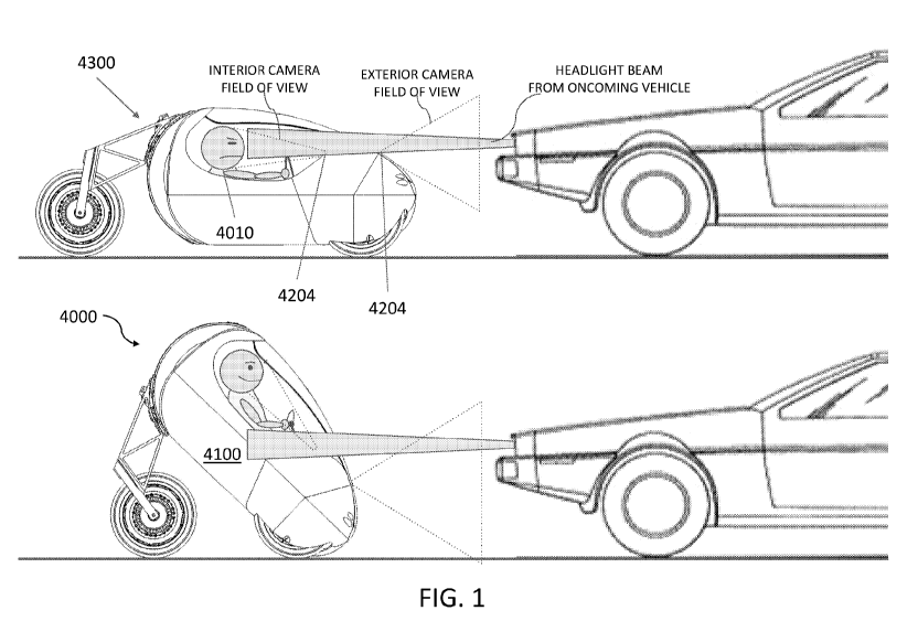
conventional vehicle is
1
CA 03115786 2021-04-08
WO 2020/077194 PCT/US2019/055814
predominantly a single rigid body during operation. Thus, the FOV of the cabin
is determined
primarily during the design phase of the vehicle and is thus not readily
reconfigurable after
production without expensive and/or time consuming modifications.
SUMMARY
[0004] Embodiments described herein are directed to a vehicle that includes a
reactive system that
responds, in part, to a change in the position and/or orientation of an
operator (also referred to as
a "driver"). (A vehicle with a reactive system may be called a reactive
vehicle.) For example, the
reactive system may adjust a FOV of the operator as the operator moves their
head. This may be
accomplished in several ways, such as by physically actuating an articulated
joint of the vehicle in
order to change the position of the operator with respect to the environment
or by adjusting video
imagery displayed to the operator of a region outside the vehicle. In this
manner, the reactive
system may extend the operator's FOV, thus providing the operator greater
situational awareness
of the vehicle's surroundings while enabling the operator to maintain
awareness along the vehicle's
direction of travel. The reactive system may also enable the operator to see
around and/or over
objects by adjusting a position of a camera on the vehicle or the vehicle
itself, which is not possible
with conventional vehicles.
[0005] In one aspect, the position and/or orientation of the driver may be
measured by one or more
sensors coupled to the vehicle. The sensors may be configured to capture
various types of data
associated with the operator. For example, the sensor may include a camera to
acquire red, green,
blue (RGB) imagery of the operator and a depth map sensor to acquire a depth
map of the operator.
The RGB imagery and the depth map may be used to determine coordinates of
various facial and/or
pose features associated with the operator, such as an ocular reference point
of the driver's head.
The coordinates of the various features of the operator may be measured as a
function of time and
used as input to actuate the reactive system.
[0006] The use of various data types to determine the features of the operator
may reduce the
occurrence of false positives (i.e., detecting spurious features) and enable
feature detection under
various lighting conditions. The detection of these features may be
accomplished using several
methods, such as a convolutional neural network. A motion filtering system
(e.g., a Kalman filter)
may also be used to ensure the measured features of the operator change
smoothly as a function of
2
CA 03115786 2021-04-08
WO 2020/077194 PCT/US2019/055814
time by reducing, for example, unwanted jitter in the RGB imagery of the
operator. The depth map
may also be used with the RGB image in several ways. For example, the depth
may mask the RGB
image such that a smaller portion of the RGB image is used for feature
detection thereby reducing
the computational cost.
[0007] The one or more sensors may also measure various environmental
conditions, such as the
type of road surface, the vehicle speed and acceleration, obstacles near the
vehicle, and/or the
presence of precipitation. The measured environmental conditions may also be
used as inputs to
the reactive system. For example, the environmental conditions may modify the
magnitude of a
response of the reactive system (e.g., adjustment to ride height) based on the
speed of the vehicle
(e.g., highway driving vs. city driving). In some cases, the environmental
conditions may also be
used as a gate where certain conditions (e.g., vehicle speed, turn rate, wheel
traction), if met, may
prohibit activation of the reactive system in order to maintain safety of the
operator and the vehicle.
[0008] The reactive system may include a video-based mirror assembled using a
camera and a
display. The camera may be coupled to the vehicle and oriented to acquire
video imagery of a
region outside the vehicle (e.g., the rear of the vehicle). The display may be
used to show the video
imagery of the region to the operator. As the driver moves, the video imagery
shown on the display
may be transformed in order to adjust the FOV of the region captured by the
camera. For instance,
the operator may rotate their head and the video imagery correspondingly
shifted (e.g., by panning
the camera or shifting the portion of the video imagery being shown on the
display) to emulate a
response similar to a conventional mirror. The reactive system may include
multiple cameras such
that the aggregate FOV of the cameras substantially covers the vehicle
surroundings, thus reducing
or, in some instances, eliminating the operator's blind spots when operating
the vehicle. The video
imagery acquired by the multiple cameras may be displayed on one or more
displays.
[0009] The reactive system may include an articulated joint to physically
change a configuration
of the vehicle. The articulated joint may include one or more mechanisms, such
as an active
suspension of a vehicle to adjust the tilt/ride height of the vehicle and/or a
hinge that causes the
body of the vehicle to change shape (e.g., rotating a front section of the
vehicle with respect to a
tail section of the vehicle). In one example, the articulated joint may
include a guide structure that
defines a path where a first portion of the vehicle is movable relative to a
second portion along the
path, a drive actuator to move the first portion of the vehicle along the
path, and a brake to hold
3
CA 03115786 2021-04-08
WO 2020/077194 PCT/US2019/055814
the first portion of the vehicle at a particular position along the path.
[0010] The articulated joint may be used to modify the position of the
operator with respect to the
environment. For example, the reactive system may use the articulated joint to
tilt the vehicle when
the operator tilts their head to look around an object (e.g., another
vehicle). In another example,
the reactive system may increase the ride height of the vehicle when the
operator pitches their head
upwards in order to look over an object (e.g., a barrier). In such cases, the
reactive system may be
configured to actuate the articulated joint in a manner that doesn't
compromise vehicle stability.
For instance, the reactive system may reduce the magnitude of the actuation
or, in some instances,
prevent the articulated joint from actuating when the vehicle is traveling at
high speeds. The
reactive system may also actuate the articulated joint in conjunction with
explicit operator
commands (e.g., commands received from input devices, such as a steering
wheel, an accelerator,
a brake).
[0011] Another method of operating a (reactive) vehicle includes receiving a
first input from an
operator of the vehicle using a first sensor and receiving a second input from
an environment
outside the vehicle using a second sensor. A processor identifies a
correlation between the first
and second inputs and generating a behavior-based command based on the
correlation. This
behavior-based command causes the vehicle to move with a pre-defined behavior
when applied to
an actuator of the vehicle. The processor generates a combined command based
on the behavior-
based command, an explicit command from the operator via an input device
operably coupled to
the processor, and the second input. It adjusts and/or filters the combined
command to maintain
stability of the vehicle, then actuates the actuator of the vehicle using the
adjusted and/or filtered
combined command.
[0012] Although the above examples of a reactive system are described in the
context of
modifying a FOV of an operator and/or a camera, the reactive system and the
various components
therein may also be used for other applications. For example, the reactive
system may be used as
a security system for the vehicle. The reactive system may recognize and allow
access to the
vehicle for approved individuals while impeding access for other individuals
(e.g., by actuating
the vehicle in order to prevent entry). In another example, the reactive
system may cause the
vehicle to via an articulated joint, emit a sound (e.g., honking), and/or to
turn on/flash its headlights
such that the operator is able to readily locate the vehicle (e.g., in a
parking lot containing a
4
CA 03115786 2021-04-08
WO 2020/077194 PCT/US2019/055814
plurality of vehicles). In another example, the vehicle may have an autonomous
mode of operation
where the reactive system is configured to command the vehicle to follow an
operator located
outside the vehicle. This may be used, for example, to record video imagery of
the operator as the
operator moves within an environment. In another example, the reactive system
may adjust the
position of the operator (e.g., via an articulated joint) in order to reduce
glare on the operator's
ocular region.
[0013] All combinations of the foregoing concepts and additional concepts
discussed in greater
detail below (provided such concepts are not mutually inconsistent) are
contemplated as being part
of the inventive subject matter disclosed herein. In particular, all
combinations of claimed subject
matter appearing at the end of this disclosure are contemplated as being part
of the inventive
subject matter disclosed herein. It should also be appreciated that
terminology explicitly employed
herein that also may appear in any disclosure incorporated by reference should
be accorded a
meaning most consistent with the particular concepts disclosed herein.
BRIEF DESCRIPTION OF THE DRAWINGS
[0014] The skilled artisan will understand that the drawings primarily are for
illustrative purposes
and are not intended to limit the scope of the inventive subject matter
described herein. The
drawings are not necessarily to scale; in some instances, various aspects of
the inventive subject
matter disclosed herein may be shown exaggerated or enlarged in the drawings
to facilitate an
understanding of different features. In the drawings, like reference
characters generally refer to
like features (e.g., functionally similar and/or structurally similar
elements).
[0015] FIG. 1 shows an articulated vehicle that articulates to shift the
driver's field of view in
response to a headlight beam from an oncoming vehicle.
[0016] FIG. 2 shows a coordinate system with an origin centered on the
driver's head.
[0017] FIG. 3 shows a seat with calibration features for a reactive vehicle
system.
[0018] FIG. 4 shows an exemplary reactive mirror in a vehicle.
[0019] FIG. 5A shows the various components of the reactive mirror of FIG. 4
disposed in and on
a conventional vehicle and the field of view (FOV) of each camera.
[0020] FIG. 5B shows the various components of the reactive mirror of FIG. 4
disposed in and on
CA 03115786 2021-04-08
WO 2020/077194 PCT/US2019/055814
an articulated vehicle and the FOV of each camera.
[0021] FIG. 6 illustrates a method for acquiring and transforming video
imagery acquired by the
cameras of the reactive mirror of FIG. 4 based on the position and/or
orientation of an operator.
[0022] FIG. 7A shows a side, cross-sectional view of an exemplary vehicle with
an articulated
joint.
[0023] FIG. 7B shows a side view of the vehicle of FIG. 7A.
[0024] FIG. 7C shows a top view of the vehicle of FIG. 7B.
[0025] FIG. 7D shows a side view of the vehicle of FIG. 7B in a low profile
configuration where
the outer shell of the tail section is removed.
[0026] FIG. 7E shows a side view of the vehicle of FIG. 7B in a high profile
configuration where
the outer shell of the tail section is removed.
[0027] FIG. 8A shows a perspective view of an exemplary articulated joint in a
vehicle.
[0028] FIG. 8B shows a side view of the articulated joint of FIG. 8A.
[0029] FIG. 8C shows atop, side perspective view of the articulated joint of
FIG. 8A.
[0030] FIG. 8D shows a bottom, side perspective view of the articulated joint
of FIG. 8A.
[0031] FIG. 8E shows a top, side perspective view of the carriage and the
track system in the guide
structure of FIG. 8A.
[0032] FIG. 8F shows a top, side perspective view of the track system of FIG.
8E.
[0033] FIG. 8G shows a cross-sectional view of a bearing in a rail in the
track system of FIG. 8F.
[0034] FIG. 9 shows a flow diagram of a method for operating a reactive system
of a vehicle.
[0035] FIG. 10A shows various input parameters associated with an operator
controlling a vehicle
and exemplary ranges of the input parameters when the vehicle is turning.
[0036] FIG. 10B shows various input parameters associated with an environment
surrounding the
vehicle and exemplary ranges of the input parameters when the vehicle is
turning.
[0037] FIG. 11A shows a displacement of an articulated vehicle along an
articulation axis as a
function of a driver position where the limit to the displacement is adjusted
to maintain stability.
6
CA 03115786 2021-04-08
WO 2020/077194 PCT/US2019/055814
[0038] FIG. 11B shows a displacement of an articulated vehicle along an
articulation axis as a
function of a driver position where the rate of change of the displacement is
adjusted to maintain
stability.
[0039] FIG. 12A shows an articulated vehicle equipped with a sensor to monitor
the position of a
second vehicle using video imagery and a depth map acquired by the sensor.
[0040] FIG. 12B shows the articulated vehicle of FIG. 12A being tilted, which
changes the
position of the second vehicle measured with respect to the sensor on the
articulated vehicle.
[0041] FIG. 13 shows an articulated vehicle whose ride height is adjusted to
increase the FOV of
an operator and/or a sensor.
[0042] FIG. 14A shows an articulated vehicle with a limited FOV due to the
presence of a second
vehicle.
[0043] FIG. 14B shows the articulated vehicle of FIG. 14A tilted to see around
the second vehicle.
[0044] FIG. 15A shows a top view of an articulated vehicle and the FOV of the
articulated vehicle.
[0045] FIG. 15B shows a front view of the articulated vehicle and the FOV of
the articulated
vehicle of FIG. 15A.
[0046] FIG. 15C shows a side view of the articulated vehicle of FIG. 15A
traversing a series of
steps.
[0047] FIG. 16 shows an articulated vehicle that identifies a person approach
the vehicle and, if
appropriate, reacts to prevent the person from accessing the articulated
vehicle.
[0048] FIG. 17 shows an articulated vehicle that acquires video imagery of an
operator located
outside the articulated vehicle.
DETAILED DESCRIPTION
[0049] Following below are more detailed descriptions of various concepts
related to, and
implementations of, a reactive vehicle system, a reactive mirror system, an
articulated vehicle, and
methods for using the foregoing. The concepts introduced above and discussed
in greater detail
below may be implemented in multiple ways. Examples of specific
implementations and
applications are provided primarily for illustrative purposes so as to enable
those skilled in the art
7
CA 03115786 2021-04-08
WO 2020/077194 PCT/US2019/055814
to practice the implementations and alternatives apparent to those skilled in
the art.
[0050] The figures and example implementations described below are not meant
to limit the scope
of the present implementations to a single embodiment. Other implementations
are possible by
way of interchange of some or all of the described or illustrated elements.
Moreover, where certain
elements of the disclosed example implementations may be partially or fully
implemented using
known components, in some instances only those portions of such known
components that are
necessary for an understanding of the present implementations are described,
and detailed
descriptions of other portions of such known components are omitted so as not
to obscure the
present implementations.
[0051] The discussion below describes various examples of a vehicle, a
reactive system, a reactive
mirror, and an articulated mechanism. One or more features discussed in
connection with a given
example may be employed in other examples according to the present disclosure,
such that the
various features disclosed herein may be readily combined in a given system
according to the
present disclosure (provided that respective features are not mutually
inconsistent).
A Vehicle with a Sensor and a Reactive System
[0052] FIG. 1 shows an (articulated) vehicle 4000 with a body 4100. One or
more sensors,
including an external camera 4202 and an internal camera 4204, may be mounted
to the body 4100
to measure various inputs associated with the vehicle 4000 including, but not
limited to a pose
and/or an orientation of an operator (e.g., a driver 4010), operating
parameters of the vehicle 4000
(e.g., speed, acceleration, wheel traction), and environmental conditions
(e.g., ambient lighting).
A reactive system (illustrated in FIG. 1 as an articulated joint 4300) may be
coupled to the vehicle
4000 to modify some aspect of the vehicle 4000 (e.g., changing a FOV of the
operator 4010,
traversing variable terrain, etc.) based, in part, on the inputs measured by
the sensors 4202 and
4204. In FIG. 1, for example, the reactive system 4300 articulates the vehicle
to move the user's
head out of the path of on an oncoming vehicle's headlight beam(s) as detected
by the external
camera 4204. The vehicle 4000 may also include a processor (not shown) to
manage the sensors
4202 and 4204 and the reactive system 4300 as well as the transfer of data
and/or commands
between various components in the vehicle 4000 and its respective subsystems.
[0053] The reactive system 4300 may include or be coupled to one or more
sensors to acquire
various types of data associated with the vehicle 4000. For example, the
interior camera 4204 may
8
CA 03115786 2021-04-08
WO 2020/077194 PCT/US2019/055814
acquire both depth and red-green-blue (RGB) data of the cabin of the vehicle
4000 and/or the
operator 4010. Each pixel of a depth frame may represent the distance between
an object
subtending the pixel and het capture source of the depth map sensor. The depth
frame may be
acquired using structured infrared (IR) projections and two cameras in a
stereo configuration (or
similar depth capture). The depth frames are used to generate a depth map
representation of the
operator 4010 and the vehicle cabin. RGB frames may be acquired using a
standard visible light
camera. Other types of data acquired by the sensor 4200 may include, but is
not limited to the
operator's heart rate, gait, and facial recognition of the operator 4010.
[0054] The external camera 4202 and/or other sensors, including inertial
measurement units or
gyroscopes, may be configured to acquire various vehicle parameters and/or
environmental
conditions including, but not limited to the orientation of the vehicle 4000,
the speed of the vehicle
4000, the suspension travel, the acceleration rate, the topology of the road
surface, precipitation,
day/night sensing, road surface type (e.g., paved smooth, paved rough, gravel,
dirt), other
objects/obstructions near the vehicle 4000 (e.g., another car, a person, a
barrier). The operational
frequency of these sensors may be at least 60 Hz and preferably 120 Hz.
[0055] Various operating parameters associated with each sensor may be stored
including, but not
limited to intrinsic parameters related to the sensor (e.g., resolution,
dimensions) and extrinsic
parameters (e.g., the position and/or orientation of the internal camera 4204
within the coordinate
space of the vehicle 4000). Each sensor's operating parameters may be used to
convert between a
local coordinate system associated with that sensor and the vehicle coordinate
system. For
reference, the coordinate system used herein may be a right-handed coordinate
system based on
International Organization for Standards (ISO) 16505-2015. In this coordinate
system, the positive
x-axis is pointed along the direction opposite to the direction of forward
movement of the vehicle
4000, the z-axis is orthogonal to the ground plane and points upwards, and the
y-axis points to the
right when viewing the forward movement direction.
[0056] The processor (also referred to herein as a "microcontroller") may be
used to perform
various functions including, but not limited to processing input data acquired
by the sensor(s) (e.g.,
filtering out noise, combining data from various sensors), calculating
transformations and/or
generating commands to modify the reactive system 4300, and communicatively
coupling the
various subsystems of the vehicle 4000 (e.g., the external camera 4204 to the
reactive system
9
CA 03115786 2021-04-08
WO 2020/077194 PCT/US2019/055814
4300). For example, the processor may be used to determine the position and/or
orientation of the
operator 4010 and generate an image transformation that is applied to video
imagery. The
processor may generally constitute one or more processors that are
communicatively coupled
together. In some cases, the processor may be a field programmable gate array
(FPGA).
[0057] As described above, the internal camera 4202 may detect the position
and/or orientation of
the operator 4010 (e.g., the operator's head or body) in vehicle coordinate
space. In the following
example, the internal camera 4202 acquires both depth and RGB data of the
operator 4010. Prior
to feature detection, the processor may first align the RGB imagery and depth
frames acquired by
the internal camera 4202 such that corresponding color or depth data may be
accessed using the
pixel coordinates of either frame of RGB and depth data. The processing of
depth maps typically
uses fewer computational resources compared to the processing of an RGB frame.
In some cases,
the depth map may be used to limit and/or mask an area of the RGB frame for
processing. For
example, the depth map may be used to extract a portion of the RGB frame
corresponding to a
depth range of about 0.1 m to about 1.5 m for feature detection. Reducing the
RGB frame in this
manner may substantially reduce the computational power used to process the
RGB frame as well
as reducing the occurrence of false positives.
[0058] Feature detection may be accomplished in several ways. For example, pre-
trained machine
learning models (e.g., convolutional neural networks) may utilize depth, RGB,
and/or a
combination (RGBD) data to detect features of the operator 4010. The output of
the model may
include pixel regions corresponding to the body, the head, and/or facial
features. The model may
also provide estimates of the operator's pose. In some cases, once the
processor 4400 identifies
the operator's head, the processor 4400 may then estimate an ocular reference
point of the operator
4010 (e.g., a middle point between the operator's eyes as shown in FIG. 2).
The ocular reference
point may then be de-projected and translated into coordinates within the
vehicle reference frame.
As described, feature detection may be a software construct, thus the models
used for feature
detection may be updated after the time of manufacture to incorporate advances
in computer vision
and/or to improve performance.
[0059] The sensors (e.g., the internal camera 4202) and the reactive system
4300 may also be
calibrated to the operator 4010. Generally, the operator's height and location
within the cabin of
the vehicle 4000 (e.g., a different driving position) may vary overtime.
Variations in the operator's
CA 03115786 2021-04-08
WO 2020/077194 PCT/US2019/055814
position and orientation may prevent the reactive system 4300 from being able
to properly adjust
the vehicle 4000 to aid the operator 4010 if the vehicle 4000 is not
calibrated specifically to the
operator 4010. The operator 4010 may activate a calibration mode using various
inputs in the
vehicle 4000 including, but not limited to pushing a physical button,
selecting a calibration option
on the control console of the vehicle 4000 (e.g., the infotainment system),
and/or using a voice
command.
[0060] Generally, calibrations may be divided into groups relating to (1) the
operator's physical
position and movement and (2) the operator's personal preferences.
Calibrations related to the
operator's physical position and movement may include establishing the
operator's default sitting
position and the operator's normal ocular point while operating the vehicle
4000 in vehicle
coordinates within the vehicle 4000 and the operator's range of motion, which
in turn affects the
response range of the reactive system 4300 to changes in the position of the
operator's head. The
sensor 4200 may be used to acquire the operator's physical position and
movement and the
resultant ocular reference point may be stored for later use when actuating
the reactive system
4300.
[0061] During calibration, the operator 4010 may be instructed to move their
body in a particular
manner. For example, audio or visual prompts from the vehicle's speakers and
display may prompt
the operator 4010 to sit normally, move to the right, or move to the left. The
processor records the
ocular reference point at each position to establish the default position and
the range of motion.
The prompts may be delivered to the operator 4010 in several ways, including,
but not limited to
visual cues and/or instructions shown on the vehicle's infotainment system and
audio instructions
through the vehicle's speakers. The processor may record the ocular reference
point in terms of
the coordinate system of the vehicle 4000 so that the ocular reference point
can be used as an input
for the various components in the reactive system 4300.
[0062] The internal camera 4202 may also be calibrated to a seat in the
vehicle 4000, which may
provide a more standardized reference to locate the internal camera 4202 (and
the driver 4010)
within the vehicle 4000. FIG. 3 shows a seat 4110 that includes calibration
patterns 4120 to be
detected by the sensor 4200. The shape and design of the calibration patterns
4120 may be known
beforehand. They may be printed in visible ink or in invisible ink (e.g., ink
visible only at near-
infrared wavelengths). Alternatively, or in addition, the seat 4110 may have a
distinctive shape or
11
CA 03115786 2021-04-08
WO 2020/077194 PCT/US2019/055814
features (e.g., asymmetric features) that can be used as fiducial markers for
calibration. By imaging
the calibration pattern 4120 (and the seat 4110), the relative distance and/or
orientation of the
sensor 4200 with respect the seat may be found. In some cases, the calibration
patterns 4120 may
be formed at visible wavelengths (e.g., directly observable with the human
eye) or infrared
wavelengths (e.g., invisible to the human eye and detectable using only
infrared imaging sensors).
[0063] Calibrations related to the operator's personal preferences may vary
based on the type of
reactive system 4300 being used. For example, the reactive system 4300 may
utilize a video-based
mirror that allows the operator 4010 to manually adjust video imagery shown in
a manner similar
to adjusting previous side-view mirrors. In another example, the reactive
system 4300 may include
an articulated joint. The operator 4010 may be able to tailor the magnitude
and/or rate of actuation
of the articulated joint (e.g., a gentler actuation may provide greater
comfort, a more rapid,
aggressive actuation may provide greater performance).
A Reactive System with a Video-Based Mirror
[0064] FIG. 4 shows an exemplary reactive system 4300 that includes a video-
based mirror 4320.
As shown, the mirror 4320 may include a camera 4330 coupled to the processor
4400 (also referred
to as a microcontroller unit (MCU) 4400) to acquire source video imagery 4332
(also referred to
as the "source video stream") of a region of the environment 4500 outside the
vehicle 4000. The
mirror 4320 may also include a display 4340 coupled to the MCU 4400 to show
transformed video
imagery 4342 (e.g., a portion of the source video imagery 4332) to the
operator 4010. The
processor 4400 may apply a transformation to the source video imagery 4332 to
adjust the
transformed video imagery 4342 (e.g., a FOV and/or an angle of view) shown to
the operator 4010
in response to the sensor 4200 detecting movement of the operator 4010. In
this manner, the video-
based mirror 4320 may supplement or replace conventional mirrors (e.g., a side-
view, a rear-view
mirror) in the vehicle 4000. For example, the video-based mirror 4320 may be
used to reduce
aerodynamic drag typically encountered when using conventional mirrors. In
some cases, the
mirror 4320 may be classified as a Camera Monitoring System (CMS) as defined
by ISO 16505-
2015 .
[0065] The mirror 4320 may acquire source video imagery 4332 that covers a
sufficient portion
of the vehicle surroundings to enable safe operation of the vehicle 4000.
Additionally, the mirror
4320 may reduce or mitigate scale and/or geometric distortion of the
transformed video imagery
12
CA 03115786 2021-04-08
WO 2020/077194 PCT/US2019/055814
4342 shown on the display 4340. The mirror 4320 may also be configured to
comply with local
regulations. Conventional driver side and center mirrors are generally unable
to exhibit these
desired properties. For example, side view and center mirrors should provide
unit magnification
in the United States, which means the angular height and width of objects
displayed should match
the angular height and width of the same object as viewed directly at the same
distance (Federal
Motor Vehicle Safety Standards No. 111).
[0066] The camera 4330 may be used individually or as part of an array of
cameras 4330 that each
cover a respective region of the environment 4500 outside the vehicle 4000.
The camera 4330 may
include a lens (not shown) and a sensor (not shown) to acquire the source
video imagery 4332 that,
in combination, defines a FOV 4334 of the camera 4330.
[0067] FIGS. 5A and 5B shows an articulated vehicle 4000 and a conventional
vehicle 4002 that
each includes camera 4330a, 4330b, and 4330c (collectively, cameras 4330) to
cover left side,
right side, and rear regions outside the vehicle 4000, respectively. Each
vehicle 4000, 4002 also
includes corresponding displays 4340a and 4340b showing transformed video
imagery 4342
acquired by the cameras 4330a, 4330b, and 4330c. (The conventional vehicle may
also include an
additional display 4340c in place of a rearview mirror.) As shown, the cameras
4330 may be
oriented to have a partially overlapping FOV 4334 such that no blind spots are
formed between
the different cameras 4330.
[0068] The placement of the cameras 4330 on the vehicle 4000 may depend on
several factors.
For example, the cameras 4330 may be placed on the body 4100 to capture a
desired FOV 4334
of the environment 4500 (as shown in FIGS. 5A and 5B). The cameras 4330 may
also be positioned
to reduce aerodynamic drag on the vehicle 4000. For example, each camera 4330
may be mounted
within a recessed opening on the door and/or side panel of the body 4100 or
the rearward-facing
portion of trunk of the vehicle 4000. The placement of the cameras 4330 may
also depend, in part,
on local regulations and/or guidelines based on the location in which the
vehicle 4000 is being
used (e.g., ISO 16505).
[0069] The FOVs 4334 of the cameras 4330 may be sufficiently large to support
one or more
desired image transformations applied to the source video imagery 4332 by the
processor 4400.
For example, the transformed video imagery 4342 shown on the display 4340 may
correspond to
a portion of the source video imagery 4332 acquired by the camera 4330 and
thus have a FOV
13
CA 03115786 2021-04-08
WO 2020/077194 PCT/US2019/055814
4344 smaller than the FOV 4334. The sensor of the camera 4330 may acquire the
source video
imagery 4332 at a sufficiently high resolution such that the transformed video
imagery 4342 at
least meets the lowest resolution of the display 4340 across the range of
supported image
transformations.
[0070] The size of the FOV 4334 may be based, in part, on the optics used in
the camera 4330.
For example, the camera 4330 may use a wide-angle lens in order to increase
the FOV 4334, thus
covering a larger region of the environment 4500. The FOV 4334 of the camera
4330 may also be
adjusted via a motorized mount that couples the camera 4330 to the body 4100
of the vehicle 4000.
The motorized mount may rotate and/or pan the camera 4330, thus shifting the
FOV 4334 of the
camera 4330. This may be used, for instance, when the camera 4330 includes a
lens with a longer
focal length. The motorized mount may be configured to actuate the camera 4330
at a frequency
that enables a desired responsiveness to the video imagery 4342 shown to the
operator 4010. For
example, the motorized mount may actuate the camera 4330 at about 60 Hz. In
cases where the
motorized mount actuates the camera 4330 at lower frequencies (e.g., 15 Hz),
the processor 4400
may generate additional frames (e.g., via interpolation) in order to up-sample
the video imagery
4342 shown on the display 4340.
[0071] Each camera 4330 may acquire the source video imagery 4332 at a
variable frame rate
depending on the lighting conditions and the desired exposure settings. For
instance, the camera
4330 may nominally acquire the source video imagery 4332 at a frame rate of at
least about 30
frames per second (FPS) and preferably 60 FPS. However, in low light
situations, the camera 4330
may acquire source video imagery 4332 at a lower frame rate at least about 15
FPS.
[0072] Each camera 4330 may also be configured to acquire source video imagery
4332 at various
wavelength ranges including, but not limited to visible, near-infrared (NIR),
mid-infrared (MIR),
and far-infrared (FIR) ranges. In some applications, an array of cameras 4330
disposed on the
vehicle 4000 may be used to cover one or more wavelength ranges (e.g., one
camera 4330 acquires
visible video imagery and another camera 4330 acquires NIR video imagery) in
order to enable
multiple modalities when operating the mirror 4320. For example, the processor
4400 may show
only IR video imagery on the display 4340 when the sensor 4200 detects the
vehicle 4000 is
operating in low visibility conditions (e.g., nighttime driving, fog).
[0073] The reactive system 4300 may store various operating parameters
associated with each
14
CA 03115786 2021-04-08
WO 2020/077194 PCT/US2019/055814
camera 4330 including, but not limited to intrinsic parameters related to the
properties of the optics
and/or the sensor (e.g., focal length, aspect ratio, sensor size), extrinsic
parameters (e.g., the
position and/or orientation of the camera 4330 within the coordinate space of
the vehicle 4000),
and distortion coefficients (e.g., radial lens distortion, tangential lens
distortion). The operating
parameters of the camera 4330 may be used to modify the transformations
applied to the source
video imagery 4332.
[0074] The display 4340 may be a device configured to show the transformed
video imagery 4342
corresponding to the FOV 4344. As shown in FIGS. 5A and 5B, the vehicle 4000
may include one
or more displays 4340. The display 4340 may generally show the video imagery
4332 acquired by
one or more cameras 4330. For example, the display 4340 may be configured to
show the
transformed video imagery 4342 of multiple cameras 4330 in a split-screen
arrangement (e.g., two
transformed video imagery 4342 displayed side-by-side). In another example,
the processor 4400
may transform the source video imagery 4332 acquired by multiple cameras 4330
such that the
transformed video imagery 4342 shown on the display 4340 transitions
seamlessly from one
camera 4330 to another camera 4330 (e.g., the source video imagery 4332 are
stitched together
seamlessly). The vehicle may also multiple displays 4340 that each correspond
to a camera 4330
on the vehicle 4000.
[0075] The placement of the display 4340 may depend on several factors. For
example, the
position and/or orientation of the display 4340 may be based, in part, on the
nominal position of
the operator 4010 or the driver's seat of the vehicle of the vehicle 4000. For
example, one display
4340 may be positioned to the left of a steering wheel and another display
4340 positioned to the
right of the steering wheel. The pair of displays 4340 may be used to show
transformed video
imagery 4342 from respective cameras 4330 located on the left and right sides
of the vehicle 4000.
The displays 4340 may be placed in a manner that allows the operator 4010 to
see the transformed
video imagery 4342 without having to lose sight of the vehicle's surroundings
along the direction
of travel. Additionally, the location of the display 4340 may also depend on
local regulations
and/or guidelines based on the location in which the vehicle 4000 is being
used similar to the
camera 4330.
[0076] In some cases, the display 4340 may also be touch sensitive in order to
provide the operator
4010 the ability to input explicit commands to control the video-based mirror
4320. For example,
CA 03115786 2021-04-08
WO 2020/077194 PCT/US2019/055814
the operator 4010 may touch the display 4340 with their hand and apply a
swiping motion in order
to pan and/or scale the portion of the transformed video imagery 4342 shown on
the display 4340.
When calibrating the video-based mirror 4320, the offset of the display 4340,
which will be
discussed in more detail below, may be adjusted via the touch interface.
Additionally, the operator
4010 may use the touch interface to adjust various settings of the display
4340 including, but not
limited to the brightness and contrast.
[0077] The reactive system 4300 may store various operating parameters
associated with each
display 4340 including, but not limited to intrinsic properties of the display
4340 (e.g., the display
resolution, refresh rate, touch sensitivity, display dimensions), extrinsic
properties (e.g., the
position and/or orientation of the display 4340 within the coordinate space of
the vehicle 4000),
and distortion coefficients (e.g., the curvature of the display 4340). The
operating parameters of
the display 4340 may be used by the processor 4400 to perform transformations
to the video
imagery 4332.
[0078] As described above, the processor 4400 may be used to control the
reactive system 4300.
In the case of the video-based mirror 4320, the processor 4400 may communicate
with the display
4340 and the camera 4330 using a high-speed communication bus based, in part,
on the particular
types of cameras 4330 and/or displays 4340 used (e.g., the bitrate of the
camera 4330, resolution
and/or refresh rate of the display 4340). In some cases, the communication bus
may also be based,
in part, on the type of processor 4400 used (e.g., the clock speed of a
central processing unit and/or
a graphics processing unit). The processor 4400 may also communicate with
various components
of the video-based mirror 4320 and/or other subsystems of the vehicle 4000
using a common
communication bus, such as a Controller Area Network (CAN) bus.
[0079] The video-based mirror 4320 in the reactive system 4300 may acquire
source video
imagery 4332 that is modified based on the movement of the operator 4010 and
shown as
transformed video imagery 4342 on the display 4340. These modifications may
include applying
a transformation to the source video imagery 4332 that extracts an appropriate
portion of the source
video imagery 4332 and prepares the portion of the video imagery 4332 to be
displayed to the
operator 4010. In another example, transformations may be used to modify the
FOV 4344 of the
transformed video imagery 4342 such that the mirror 4320 responds in a manner
similar to a
conventional mirror. For instance, the FOV 4344 may widen as the operator 4010
moves closer to
16
CA 03115786 2021-04-08
WO 2020/077194 PCT/US2019/055814
the display 4340. Additionally, the FOV 4344 of the transformed video imagery
4342 may pan as
the operator 4010 shifts side to side.
[0080] FIG. 6 shows a method 600 of transforming source video imagery 4332
acquired by the
camera 4330 based, in part, on changes to the position and/or orientation of
the head of the operator
4010. The method 600 may begin with sensing the position and/or orientation of
the operator's
head using the sensor 4200 (step 602). As described above, the sensor 4200 may
acquire data of
the operator's head (e.g., an RGB image and/or a depth map). The processor
4400 may then
determine an ocular reference point of the operator 4010 based on the data
acquired by the sensor
4200 (step 604). If the processor 4400 is able to determine the ocular
reference point (step 606), a
transformation is then computed and applied to modify the source video imagery
4332 (step 610).
[0081] The transformation may be calculated using a model of the video-based
mirror 4320 and
the sensor 4200 in the vehicle 4000. The model may receive various inputs
including, but not
limited to the ocular reference point, the operating parameters of the camera
4330 (e.g., intrinsic
and extrinsic parameters, distortion coefficients), the operating parameters
of the display
4340(e.g., intrinsic and extrinsic parameters, distortion coefficients), and
manufacturer and user
calibration parameters. Various types of transformations may be applied to the
source video
imagery 4332 including, but not limited to panning, rotating, and scaling. The
transformations may
include applying a series of matrix transformations and signal processing
operations to the source
video imagery 4332.
[0082] In one example, the transformation applied to the source video imagery
4332 may be based
only on the ocular reference point and the user calibration parameters. In
particular, the distance
between the ocular reference point and the default sitting position of the
operator 4010 (as
calibrated) may be used to pan and/or zoom in on a portion of the source video
imagery 4332 using
simple affine transformations. For instance, the magnitude of the
transformation may be scaled to
the calibrated range of motion of the operator 4010. Additionally, the pan
and/or zoom rate may
be constant such that the transformed video imagery 4342 responds uniformly to
movement by the
operator's head. In some cases, the uniform response of the mirror 4320 may
not depend on the
distance between the display 4340 and the ocular reference point of the
operator 4010.
[0083] This transformation may be preferable in vehicles 4000 where the
display(s) 4340 are
located in front of the operator 4010 and/or when the mirror 4320 is
configured to respond only to
17
CA 03115786 2021-04-08
WO 2020/077194 PCT/US2019/055814
changes in the position of the operator's head (and not changes to other
parameters such as the
viewing angle of the operator 4010 or distance between the display 4340 and
the operator 4010).
In this manner, this transformation may be simpler to implement and less
computationally
expensive (and thus faster to perform) while providing a more standardized
response for various
camera 4330 and display 4340 placements in the vehicle 4000. Additionally,
this transformation
may be applied to the source video imagery 4332 based on movement of the
operator's head.
[0084] In another example, the transformation applied to the source video
imagery 4332 may be
based, in part, on the viewing angle of the operator 4010 with respect to the
display 4340 and the
distance between the ocular reference point of the operator 4010 and the
display 4340. A
transformation that includes adjustments based on the position, viewing angle,
and distance of the
operator 4010 relative to the display 4340 may better emulate the behavior of
traditional mirrors
and, in turn, may feel more natural to the operator 4010. The processor 4400
may determine a
vector, f'
- operator, from the ocular reference point of the operator 4010 to a center
of the display
4340. The vector may then be used to determine a target FOV and pan position
for the transformed
video imagery 4342. For example, a ray casting approach may be used to define
the FOV where
rays are cast from the ocular reference point of the operator 4010 to the
respective corners of the
display 4340.
[0085] The next step is to extract a portion of the source video imagery 4332
corresponding to the
target FOV. This may involve determining the location and size of the portion
of source video
imagery 4332 used for the transformed video imagery 4342. The size of the
portion of source video
imagery 4332 may depend, in part, on the angular resolution of the camera 4330
(e.g., degrees per
pixel), which is one of the intrinsic parameters of the camera 4330. The
angular resolution of the
camera 4330 may be used to determine the dimensions of the portion of the
video imagery 4332
to be extracted. For example, the horizontal axis of the target FOV may cover
an angular range of
45 degrees. If the angular resolution of the camera 4330 is 0.1 degrees per
pixel, the portion of the
video imagery 4332 should have 450 pixels along the horizontal axis in order
to meet the target
FOV.
[0086] The location of the transformed video imagery 4342 extracted from the
source video
imagery 4332 captured by the camera 4330 may depend on the viewing angle of
the operator 4010
with respect to the display 4340. The viewing angle may be defined as the
angle between the vector
18
CA 03115786 2021-04-08
WO 2020/077194 PCT/US2019/055814
17operator and a vector,
- display, that intersects and is normal to the center of the display 4340.
Thus, collinearity of
operator and fdisplay would correspond to the ocular reference point of the
operator 4010 being aligned to the center of the display 4340. As the
operator's head moves, the
resultant viewing angle may cause the location of the transformed video
imagery 4342 to shift in
position within the source video imagery 4332. The shift in position may be
determined by
multiplying the respective components of the viewing angle (i.e., a horizontal
viewing angle and
a vertical viewing angle) by the angular resolution of the camera 4330. In
this manner, the center
point (e.g., the X and Y pixel positions) of the cropped portion may be found
with respect to the
source video imagery 4332.
[0087] If the processor 4400 is unable to determine the ocular reference point
of the operator 4010,
a default or previous transformation may be applied to the source video
imagery 4332 (step 608 in
FIG. 6). For example, a previous transformation corresponding to a previous
measurement of the
ocular reference point may be maintained such that the transformed video
imagery 4342 is not
changed if the ocular reference point is not detected. In another example, a
transformation may be
calculated based on predictions of the operator's movement. If the ocular
reference point is
measured as a function of time, previous measurements may be extrapolated to
predict the location
of the ocular reference point of the operator 4010. The extrapolation of
previous measurements
may be accomplished in one or more ways including, but not limited to a linear
extrapolation (e.g.,
the operator's movement is approximate as being linear with a sufficiently
small time increment)
and modeling of the operator's behaviors when performing certain actions
(e.g., the operator's
head moves towards the display 4340 in a substantially repeatable manner when
changing lanes).
In this manner, a sudden interruption to the detection of the ocular reference
point would not cause
the transformed video imagery 4342 to jump and/or appear choppy.
[0088] Once the transformation is determined (e.g., a new, calculated
transformation, a
default/previous transformation), the transformation is then applied to the
source video imagery
4332 to generate the transformed video imagery 4342, which is then shown on
the display 4340
(step 612 in FIG. 6). This method 600 of transforming source video imagery
4332 may be
performed at operating frequencies of at least about 60 Hz. Additionally, the
distortion coefficients
of the camera 4330 and/or the display 4340 may be used to correct radial
and/or tangential
distortion of the source video imagery 4332. Various techniques may be used to
correct distortion
19
CA 03115786 2021-04-08
WO 2020/077194 PCT/US2019/055814
such as calculating the corrected pixel positions based on prior calibration
and then remapping the
pixel positions of the source video imagery 4332 (i.e., the source video
stream) to the corrected
pixel positions in the transformed video imagery 4342 (i.e., the transformed
video stream).
[0089] As described above, the sensor 4200 and/or the reactive system 4300 may
be calibrated to
the operator 4010. For the video-based mirror 4320, calibration may include
adjusting the
transformed video imagery 4342 shown on the display 4340 to align with the
operator's head,
which may vary based on the operator's height and/or distance between the
operator's head and
the display 4340. Additionally, the operator's range of motion and/or default
position (e.g., the
operator's driving position in the vehicle 4000), as previously described, may
be used to adjust the
transformation applied to the source video imagery 4332. For example, the
operator's range of
motion may be used to scale the transformation such that the transformed video
imagery 4342 is
able to pan across the larger source video imagery 4332 (e.g., the FOV 4344 of
the transformed
video imagery 4342 may cover the FOV 4344 of the source video imagery 4332).
[0090] In another example, the operator's default position may be used as a
"baseline" position.
The baseline position may correspond to the operator 4010 having a preferred
FOV of each display
4340 (i.e., in vehicles 4000 with more than one display 4340). For example,
the transformed video
imagery 4342 shown on each display 4340 may be substantially centered with
respect to the source
video imagery 4332 acquired by each corresponding camera 4330. In another
example, the
preferred FOV may depend on local regulations or manufacturer specifications
for the vehicle
4000. In some cases, the default position of the operator 4010 may be
determined using a dynamic
calibration approach where the mirror 4320 adapts to different operators 4010
based on an
averaged position of the operator 4010 (e.g., the average position when the
operator 4010 is sitting)
and/or the range of motion as the operator 4010 uses the vehicle 4000.
[0091] The calibration of the mirror 4320 may be performed in a semi-automated
manner where
the operator 4010 is instructed to perform certain actions (e.g., moving their
extremities) in order
to measure the range of motion and default position. As previously described,
the operator 4010
may receive instructions for calibration using various systems, such as the
infotainment system of
the vehicle 4000 or the vehicle's speakers. For the video-based mirror 4320,
the display 4340 may
also be used to provide visual instructions and/or cues to the operator 4010.
The instructions and/or
cues may include one or more overlaid graphics of the vehicle 4000, the road,
and/or another
CA 03115786 2021-04-08
WO 2020/077194 PCT/US2019/055814
reference object that provides the operator 4010 a sense of scale and
orientation. Once these
measurements are performed, the processor 4400 may attempt to adjust the
transformed video
imagery 4342 shown on each display 4340 in order to provide a suitable FOV of
the vehicle
surroundings.
[0092] The operator 4010 may also be provided controls to directly adjust the
mirror 4320. In this
manner, the operator 4010 may calibrate the mirror 4320 according to their
personal preferences
similar to how a driver is able to adjust the side-view or rear-view mirrors
of a vehicle. Various
control inputs may be provided to the operator 4010 including, but not limited
to touch controls
(e.g., the infotainment system, the display 4340), physical buttons, and a
joystick. The control
inputs may allow the operator 4010 to manually pan the transformed video
imagery 4342 up, down,
left and right and/or adjust a magnification factor offset to
increase/decrease magnification of the
transformed video imagery 4342.
[0093] These adjustments may be performed by modifying the transformations
applied to the
source video imagery 4332 (e.g., adjusting the size and location of the
transformed video imagery
4342 extracted from the source video imagery 4332) and/or by physically
rotating and/or panning
the camera 4330. Additionally, the extent to which the transformed video
imagery 4342 may be
panned and/or scaled by the operator 4010 may be limited, in part, by the
source FOV 4334 and
the resolution of the source video imagery 4332. In some cases, local
regulations may also impose
limits to the panning and/or scaling adjustments applied to the transformed
video imagery 4342.
Furthermore, these manual adjustments may be made without the operator 4010
being positioned
in a particular manner (e.g., the operator 4010 does not need to be in the
default position).
[0094] After the mirror 4320 is calibrated, the operator's default position,
range of motion, and
individual offsets for each mirror 4320 in the vehicle 4000 may be stored.
Collectively, these
parameters may define the "center point" of each display 4340, which
represents the FOV of the
environment shown to the operator 4010 in the default position when
controlling the vehicle 4000.
The center point may be determined using only the default sitting position and
the offsets for each
display 4340. In some cases, the center point may correspond to a default FOV
4344 of the
transformed video imagery 4342 when the ocular reference point of the operator
4010 is not
detected.
[0095] The range of motion of the operator 4010 may be used to scale the rate
the transformed
21
CA 03115786 2021-04-08
WO 2020/077194 PCT/US2019/055814
video imagery 4342 is panned and/or scaled. Additionally, the range of motion
may be constrained
and/or otherwise obscured by the cabin of the vehicle 4000. Thus, adjusting
the magnification
scale factor of the transformed video imagery 4342 may depend, in part, on the
detectable range
of motion of the operator 4010 in the cabin of the vehicle 4000. If the
operator 4010 cannot be
located with sufficient certainty and within a predefined time period, the
mirror 4320 may default
to showing transformed video imagery 4342 corresponding to the calibrated
center point of each
display 4340.
A Reactive System with an Articulated Joint
[0096] The reactive system 4300 may also include an articulated joint that
changes the physical
configuration of the vehicle 4000 based, in part, on the behavior of the
operator 4010. For example,
the articulated joint may be part of an active suspension system on the
vehicle 4000 that adjusts
the distance between the wheel and the chassis of the vehicle 4000. The
vehicle 4000 may include
multiple, independently controlled articulated joints for each wheel to change
the ride height
and/or to tilt the vehicle 4000. In another example, the articulated joint may
change the form and/or
shape of the body 4100. This may include an articulated joint that actuates a
flatbed of a truck.
[0097] Additionally, the articulated joint may bend and/or otherwise contort
various sections of
the body 4100 (see exemplary vehicle 4000 in FIGS. 7A-7E). For example, one or
more articulated
joints and/or other actuators may actuate the payload support mechanism rather
than the vehicle
itself. For example, these actuators may adjust the position and recline angle
of the seat to
maximize comfort and/or visibility specifically for an individual operator
without necessarily
articulating the vehicle. The seat adjustment can be performed shortly after
or in anticipation of
the operator entering the vehicle. Subsequent adjustments to the seat portion
and recline angle may
be performed while the vehicle is moving, as the operator settles in over
time. In such a scenario,
it may be inefficient or unsafe to articulate the vehicle.
[0098] The articulation of both the vehicle's body 4100 and actuation of its
suspension may enable
several configurations that each provide certain desirable characteristics to
the performance and/or
operation of the vehicle 4000. The vehicle 4000 may be configured to actively
transition between
these configurations based on changes to the position and/or orientation of
the operator 4010 as
measured by the sensor 4200. In some cases, a combination of explicit inputs
by the operator 4010
(e.g., activating a lane change signal, lowering the window) and operator
behavior may control the
22
CA 03115786 2021-04-08
WO 2020/077194 PCT/US2019/055814
response of the articulated joint(s) in the vehicle 4000.
[0099] For example, the vehicle 4000 may support a low profile configuration
where the height of
the vehicle 4000 is lowered closer to the road (see FIG. 7D). The low
configuration may provide
improved aerodynamic performance by reducing the coefficient of drag and/or
reducing the frontal
area of the vehicle 4000. The low profile configuration may also increase the
wheelbase and/or
lower the center of gravity of the vehicle 4000, which improves driving
performance by providing
greater stability and cornering rates. The processor 4400 may transition
and/or maintain the vehicle
4000 at the low profile configuration when the processor 4400 determines
operator 4010 is focused
on driving the vehicle 4000 (e.g., the ocular reference point indicate the
operator 4010 is focused
on the surroundings directly in front of the vehicle 4000) and/or driving at
high speeds (e.g., on a
highway).
[0100] In another example, the vehicle 4000 may support a high profile
configuration where the
height of the vehicle 4000 is raised above the road (see FIG. 7E). The high
profile configuration
may be used to assist with ingress and/or egress of the vehicle 4000. If
combined with an
articulated seat mechanism, the seat (or more generally a cargo carrying
platform) may be
presented at a height appropriate for the operator 4010 (e.g., a worker, a
robotic automaton) to
access a payload stored in the vehicle 4000. An elevated position may also
increase the FOV of
the operator 4010 and/or any sensors disposed on the vehicle 4000 to monitor
the surrounding
environment, thus increasing situational awareness. The processor 4400 may
transition and/or
maintain the vehicle 4000 at the high profile configuration when the FOV of
the operator 4010 is
blocked by an obstruction in the environment (e.g., another vehicle, a
barrier, a person) and/or the
processor 4400 determines the operator 4010 is actively trying to look around
an obstruction (e.g.,
the ocular reference point indicates the operator's head is oriented upwards
to look over the
obstruction).
[0101] The vehicle 4000 may also support a medium profile configuration, which
may be defined
as an intermediate state between the low and high profile configurations
previously described. The
medium profile configuration may thus provide a mix of the low profile and
high profile
characteristics. For example, the medium profile configuration may provide
better visibility to the
operator 4010 while maintaining a low center of gravity for improved dynamic
performance. This
configuration may be used to accommodate a number of scenarios encountered
when operating
23
CA 03115786 2021-04-08
WO 2020/077194 PCT/US2019/055814
the vehicle 4000 in an urban environment and/or when interacting with other
vehicles or devices.
[0102] Various use cases of the medium profile configuration include but are
not limited to
adjusting the ride height to facilitate interaction with a mailbox, an
automatic teller machine
(ATM), a drive-through window, and another human standing on the side of the
road (e.g., a
neighbor or cyclist). If the vehicle 4000 is used to transport cargo (perhaps
autonomously), the
intermediate state allows for better ergonomic and mechanical interaction with
delivery and/or
loading docks, robots, and humans. These use cases may involve predictable
movement of the
operator 4010 (or the cargo). For example, the operator 4010 may lower the
window and stick their
hand out to interact with an object or person in the environment. If the
sensor 4200 detects the
window is lowered and the processor 4400 determines the operator 4010 is
sticking their hand out,
the processor 4400 may adjust the height of the vehicle 4000 to match the
height of an object
detected near the driver side window.
[0103] FIGS. 7A-7E show the vehicle 4000 that incorporates an articulated
joint 106 (also called
an articulation mechanism), a morphing section 123, and a payload positioning
joint 2100 (also
called a payload positioning mechanism) to support a payload 2000 (e.g., a
driver, a passenger,
cargo). In this example, the vehicle 4000 is a three-wheeled electric vehicle
with rear wheel
steering. The articulated joint 106 enables the vehicle 4000 to articulate or
bend about an
intermediate position along the length of the vehicle 4000, thus reconfiguring
the vehicle 4000.
[0104] The range of articulation of the vehicle 4000 may be defined by two
characteristic
configurations: (1) a low profile configuration where the wheelbase is
extended and the driver is
near the ground as shown in FIGS. 7A, 7B, 7D and (2) a high profile
configuration where the
driver is placed at an elevated position above the ground as shown in FIG. 7E.
The vehicle 4000
may be articulated to any configuration between the low profile and the high
profile configurations.
In some cases, the articulated joint 106 may limit the vehicle 4000 to a
discrete number of
configurations. This may be desirable in instances where a simpler and/or a
low power design for
the articulated joint 106 is preferred.
[0105] The vehicle 4000 may be subdivided into a front vehicle section 102 and
a tail section 104,
which are coupled together by the articulated joint 106. The front section 102
may include a body
108, which may be various types of vehicle support structures including, but
not limited to a
unibody, a monocoque frame/shell, a space frame, and a body-on-frame
construction (e.g., a body
24
CA 03115786 2021-04-08
WO 2020/077194 PCT/US2019/055814
mounted onto a chassis). In FIGS. 7A-7E, the body 108 is shown as a monocoque
frame. The body
108 may include detachable side panels (or wheel fairings) 116, fixed side
windows 125, a
transparent canopy 110 coupled to the vehicle 4000, and two front wheels 112
arranged in a
parallel configuration and mounted on the underlying body 108. The tail
section 104 may include
a rear outer shell 121, a rear windshield 124, and a steerable wheel 126. A
morphing section 123
may be coupled between the front section 102 and the tail section 104 to
maintain a smooth,
continuous exterior surface underneath the vehicle 4000 at various
configurations. In FIGS. 7D
and 7E, the rear outer shell 121 and the rear windshield 124 are removed so
that underlying
components related to at least the articulated joint 106 can be seen.
[0106] The canopy 110 may be coupled to the body 108 via a hinged arrangement
to allow the
canopy 110 to be opened and closed. In cases where the payload 2000 is a
driver, the canopy 110
may be hinged towards the top of the vehicle 4000 when in the high profile
configuration of FIG.
7E so that the driver may enter/exit the vehicle 4000 by stepping into/out of
the vehicle 4000
between the two front wheels 112.
[0107] The front wheels 112 may be powered by electric hub motors. The rear
wheel 126 may
also be powered by an electric hub motor. Some exemplary electric motors may
be found in U.S.
8,742,633, issued on June 14, 2014 and entitled "Rotary Drive with Two Degrees
of Movement"
and U.S. Pat. Pub. 2018/0072125, entitled "Guided Multi-Bar Linkage Electric
Drive System",
both of which are incorporated herein by reference in their entirety.
[0108] The rear surface of the front vehicle section 102 may be nested within
the rear outer shell
121 and shaped such that the gap between the rear outer shell 121 of the tail
section 104 and the
rear surface of the front vehicle section 102 remains small as the tail
section 104 moves relative to
the front section 102 via the articulated joint 106. As shown, the articulated
joint 106 may
reconfigure the vehicle 4000 by rotating the tail section 104 relative to the
front section 102 about
a rotation axis 111. In FIGS. 7B, 7C, and 7E, the axis of rotation 111 is
perpendicular to a plane,
which bisects the vehicle 4000. The plane may be defined to contain (1) a
longitudinal axis of the
vehicle 4000 (e.g., an axis that intersects the frontmost portion of the body
108 and the rearmost
portion of the rear outer shell 121) and (2) a vertical axis normal to a
horizontal surface onto which
the vehicle 4000 rests such.
[0109] The articulated joint 106 may include a guide structure 107 (also
called a guide mechanism)
CA 03115786 2021-04-08
WO 2020/077194 PCT/US2019/055814
that determines the articulated motion profile of the articulated joint 106.
In the exemplary vehicle
4000 shown in FIGS. 7A-7E, the guide structure 107 may include a track system
coupled to the
front section 102 and a carriage 538 coupled to the tail section 104.
Alternatively, the track system
536 may be coupled to tail section 104 and the carriage 538 coupled to the
front section 102. The
carriage 538 may move along a path defined by the track system 536, thus
causing the vehicle
4000 to change configuration. The articulated joint 106 may also include a
drive actuator 540 (also
called a drive mechanism) that moves the carriage 538 along the track system
536 to the desired
configuration. The drive actuator 540 may be electrically controllable. The
articulated joint 106
may also include a brake 1168 to hold the carriage 538 at a particular
position along the track
system 536, thus allowing the vehicle 4000 to maintain a desired
configuration.
[0110] The body 108 may also contain therein a payload positioning joint 2100.
The payload
positioning joint 2100 may orient the payload 2000 to a preferred orientation
as a function of the
vehicle 4000 configuration. As the articulated joint 106 changes the
configuration of the vehicle
4000, the payload positioning joint 2100 may simultaneously reconfigure the
orientation of the
payload 2000 with respect to the vehicle 4000 (the front section 102 in
particular). For example,
the payload positioning joint 2100 may be used to maintain a preferred driver
orientation with
respect to the ground such that the driver does not have to reposition their
head as the vehicle 4000
transitions from the low profile configuration to the high profile
configuration. In another example,
the payload positioning joint 2100 may be used to maintain a preferred
orientation of a package to
reduce the likelihood of damage to objects contained within the package as the
vehicle 4000
articulates.
[0111] The vehicle 4000 shown in FIGS. 7A-7E is one exemplary implementation
of the
articulated joint 106, the morphing section 123, and the payload positioning
joint 2100. Various
designs for the articulated joint 106, the morphing section 123, and the
payload positioning joint
2100, are respectively discussed with reference to the vehicle 4000. However,
the articulated joint
106, the morphing section 123, and the payload positioning joint 2100 may be
implemented in
other vehicle architectures either separately or in combination.
[0112] The articulated vehicle 4000 in FIGS. 7A-7E is shown to have a single
articulation DOF
(i.e., the rotation axis 111) where the tail section 104 rotates relative to
the front section 102 in
order to change the configuration of the vehicle 4000. This topology may be
preferable for a single
26
CA 03115786 2021-04-08
WO 2020/077194 PCT/US2019/055814
commuter or passenger traveling in both urban environments and the highway,
especially when
considering intermediate and endpoint interactions with the surrounding
environment (e.g.,
compact/nested parking, small space maneuverability, low speed visibility,
high speed
aerodynamic form). The various mechanisms that provide support for said
topology and use cases
may be applied more generally to a broader range of vehicles, fleet
configurations, and/or other
topologies.
[0113] For instance, the vehicle 4000 may support one or more DOF' s that may
each be
articulated. Articulation may occur about an axis resulting in rotational
motion, thus providing a
rotational DOF, such as the rotation axis 111 in FIGS. 7A-7E. Articulation may
also occur along
an axis resulting in translational motion and thus a translational DOF. The
various mechanisms
described herein (e.g., the articulated joint 106, the payload positioning
joint 2100) may also be
used to constrain motion along one or more DOF' s. For example, the
articulated joint 106 may
define a path along which a component of the vehicle 4000 moves along said
path (e.g., the carriage
538 is constrained to move along a path defined by the track system 536). The
articulated joint 106
may also define the range of motion along the path. This may be accomplished,
in part, by the
articulated joint 106 providing smooth motion induced by low force inputs
along a desired DOF
while providing mechanical constraints along other DOF' s using a combination
of high strength
and high stiffness components that are assembled using tight tolerances and/or
pressed into contact
via an external force.
[0114] The mechanisms described here may define motion with respect to an axis
or a point (e.g.,
a remote center of motion) that may or may not be physically located on the
articulated joint 106.
For example, the articulated joint 106 shown in FIGS. 7A-7E causes rotational
motion about the
rotation axis 111, which intersects the interior compartment of the body 108,
which is located
separately from the carriage 538 and the track system 536. In another example,
the payload
positioning joint 2100 may have one or more rails 2112 that define the
translational motion of a
platform (e.g., a driver's seat).
[0115] Additionally, motion along each DOF may also be independently
controllable. For
example, each desired DOF in the vehicle 4000 may have a separate
corresponding articulated
joint 106. The drive system of each articulated joint 106 may induce motion
along each DOF
independently from other DOF' s. With reference to FIGS. 7A-7E, the
articulated joint 106 that
27
CA 03115786 2021-04-08
WO 2020/077194 PCT/US2019/055814
causes rotation about the rotation axis 111 may not depend on other DOF' s
supported in the vehicle
4000.
[0116] In some cases, however, articulation along one DOF of the vehicle 4000
may be dependent
on another DOF of the vehicle 4000. For example, one or more components of the
vehicle 4000
may move relative to another component in response to the other component
being articulated.
This dependency may be achieved by mechanically coupling several DOF' s
together (e.g., one
articulated joint 106 is mechanically linked to another articulated joint 106
such that a single drive
actuator 540 may actuate both articulated joints 106 sequentially or
simultaneously). Another
approach is to electronically couple separate DOF' s by linking separate drive
actuators 540
together. For example, the payload positioning joint 2100 may actuate a driver
seat using an
onboard motor in response to the articulated joint 106 reconfiguring the
vehicle 4000 so that the
driver maintains a preferred orientation as the vehicle 4000 is reconfigured.
[0117] The articulated joint 106 may generally include a guide structure 107
that defines the
motion profile and, hence, the articulation DOF of the articulated joint 106.
The guide structure
107 may include two reference points that move relative to one another. A
first reference point
may be coupled to one component of the vehicle 4000 whilst a second reference
point may be
coupled to another component of the vehicle 4000. For example, the front
section 102 may be
coupled to a first reference point of the guide structure 107 and the tail
section 104 may be coupled
to a second reference point of the guide structure 107 such that the front
section 102 is articulated
relative to the tail section 104.
[0118] In one aspect, the guide structure 107 may provide articulation about
an axis and/or a point
that is not physically co-located with the articulated joint 106 itself. For
example, the articulated
joint 106 may be a remote center of motion (RCM) mechanism. The RCM mechanism
is defined
as having no physical revolute joint in the same location as the mechanism
that moves. Such RCM
mechanisms may be used, for instance, to provide a revolute joint located in
an otherwise
inconvenient portion of the vehicle 4000, such as the interior cabin of the
body 108 where the
payload 2000 is located or a vehicle subsystem, such as where a steering
assembly, battery pack,
or electronics resides.
[0119] The following describes several examples of the articulated joint 106
as an RCM
mechanism. However, the articulated joint 106 may not be an RCM mechanism
where the axis or
28
CA 03115786 2021-04-08
WO 2020/077194 PCT/US2019/055814
point about which the DOF is defined along may be located physically with the
components of the
articulated joint 106.
[0120] In one example, the guide structure 107 may be a carriage-track type
mechanism. The
articulated joint 106 shown in FIGS. 7A-7E is one example of this type of
mechanism. The guide
structure 107 may include the carriage and the track system 536, which are
shown in greater detail
in FIGS. 8A-8G. As shown in FIG. 8A, the track system 536 may be attached to
the front section
102. The carriage 538 may be part of the tail section 104. As shown in FIGS.
8E and 8F, the
carriage 538 may ride along a vertically oriented, curved path defined by the
track system 536.
The drive actuator 540 may be mounted on the carriage 538 to mechanically move
the carriage
538 along the track system 536 under electrical control.
[0121] The track system 536 may include two curved rails 642 that run parallel
to each other and
are both coupled to a back surface of the front vehicle section 102. The
curved rails 642 may be
similar in design. The body 108 may be made from a molded, rigid, carbon fiber
shell with a
convexly curved rear surface that forms the back surface onto which the rails
642 are attached (i.e.,
convex with respect to viewing the front vehicle section 102 from the back).
The region of the
back surface onto which the rails 642 are attached and to which they conform
represents a segment
of a cylindrical surface for which the axis corresponds to the axis of
rotation 111. In other words,
the rails 642 may have a constant radius of curvature through the region over
which the carriage
538 moves. The arc over which the rails 642 extend may be between about 90 to
about 120 .
[0122] Each rail 642 may also include a recessed region 643 that spans a
portion of the length of
the rail 642. The recessed region 643 may include one or more holes Z through
which bolts (not
shown) can attach the rail 642 to the carbon fiber shell 108. Each rail 642
may have a cross-section
substantially shaped to be an isosceles trapezoid where the narrow side of the
trapezoid is on the
bottom side of the rail 642 proximate to the front body shell 108 to which it
is attached and the
wider side of the trapezoid on the top side of the rail 642. The rails 642 may
be made of any
appropriate material including, but not limited to aluminum, hard-coated
aluminum (e.g., with
titanium nitride) to reduce oxidation, carbon fiber, fiberglass, hard plastic,
and hardened steel.
[0123] The carriage 538 shown in FIGS. 8A and 8E supports the tail section 104
of the vehicle
4000. The tail section 104 may further include the rear shell 121, the
steering mechanism 200, and
the wheel assembly 201. The carriage 538 may be coupled to the track system
536 using one or
29
CA 03115786 2021-04-08
WO 2020/077194 PCT/US2019/055814
more bearings. As shown in FIG. 8G, two bearings 644 are used for each rail
642. Each bearing
644 may include an assembly of three parts: an upper plate 645 and two tapered
side walls 646
fastened to the upper plate 645. The assembled bearing 644 may define an
opening with a cross-
section substantially similar to the rail 642 (e.g., an isosceles trapezoid),
which may be
dimensioned to be slightly larger than the rail 642 to facilitate motion
during use. The bearing 644,
as shown, may thus be coupled to the rail 642 to form a "curved dovetail"
arrangement where the
inner sidewalls of the bearing 644 may contact the tapered outer sidewalls of
the rail 642. The
bearing 644 may not be separated from the rail 642 along any other DOF besides
the desired DOF
defined by rotational motion about the rotation axis 111. FIG. 8G shows an
exaggerated
representation of the tolerances between the bearing 644 and the rail 642 for
purposes of
illustration. The tolerances, in practice, may be substantially smaller than
shown. The plate 645
and the side walls 646 may be curved to conform to the curved rail 642.
[0124] In one example, the bearing 644 may be a plain bearing where the inner
top and side
surfaces of the bearing 644 slide against the top and side wall surfaces,
respectively, of the rail 642
when mounted. The bearing 644 may also include screw holes in the top plate to
couple (e.g., via
bolts) the remainder of the carriage 538 to the track system 536.
[0125] The length of the bearing 644 (e.g., the length being defined along a
direction parallel to
the rail 642) may be greater than the width of the bearing 644. The ratio of
the length to the width
may be tuned to adjust the distribution of the load over the bearing surfaces
and to reduce the
possibility of binding between the bearing 644 and the rail 642. For example,
the ratio may be in
the range between about 3 to about 1. The bearing 644 may also have a low
friction, high force,
low wear working surface (e.g., especially the surface that contacts the rail
642). For example, the
working surface of the bearing 644 may include, but is not limited to a Teflon
coating, a graphite
coating, a lubricant, and a polished bearing 644 and/or rail 642.
Additionally, multiple bearings
644 may be arranged to have a footprint with a length to width ratio of
ranging between about 1 to
about 1.6 in order to reduce binding, increase stiffness, and increase the
range of motion. Typically,
a bearing 644 with a longer base may have a reduced range of motion whereas a
bearing 644 with
a narrower base may have a lower stiffness; hence, the length of the bearing
644 may be chosen to
balance the range of motion and stiffness, which may further depend upon other
constraints
imposed on the bearing 644 such as the size and/or the placement in the
vehicle 4000.
CA 03115786 2021-04-08
WO 2020/077194 PCT/US2019/055814
[0126] The carriage 538 may further include two frame members 539, where each
frame member
539 is aligned to a corresponding rail 642. On the side of the carriage 538
proximate to the rails
642, two cross bars 854 and 856 may be used to rigidly connect the two frame
members 539
together. The bearings 644 may be attached to the frame members 539 at four
attachment points
848a-d. On the side of the carriage 538 furthest from the rails 642, two
support bars 851 may be
used to support the wheel assembly 201 and the steering mechanism 200. The two
support bars
851 may be connected together by another cross bar 850.
[0127] The carriage 538 and the track system 536 described above is just one
example of a track-
type articulated joint 106. Other exemplary articulated joints 106 may include
a single rail or more
than two rails. As shown above, the RCM may be located in the cabin of the
vehicle 4000 where
the payload 2000 is located without having any components and/or structure
that intrudes into said
space. However, in other exemplary articulated joints 106, the RCM may be
located elsewhere
with respect to the vehicle 4000 including, but not limited to, on the
articulated joint 106, in vehicle
subsystems (e.g., in the front section 102, in the tail section 104), and
outside the vehicle 4000.
[0128] As described above, the articulated joint in the reactive system 4300
may change the
physical configuration of the vehicle 4000 in order to modify some aspect
and/or characteristic of
the vehicle 4000, such as the operator's FOV. However, in some cases, the
articulated joint may
be capable of modifying the physical configuration of the vehicle 4000 to such
an extent that the
vehicle 4000 becomes mechanically unstable, which may result in a partial or
complete loss of
control of the vehicle 4000. In order to prevent such a loss of stability when
operating the vehicle
4000, the reactive system 4300 may include a stability control unit that
imposes constraints on the
articulated joint (e.g., limiting the range of actuation, limiting the
actuation rate).
[0129] For example, the operator 4010 may lean to one side of the vehicle 4000
when changing
lanes in order to adjust their viewing angle of a rear view display, thus
enabling the operator 4010
to check whether any vehicles are approaching from behind. In response to the
operator's
movement, the articulated joint of the vehicle 4000 may actively roll the
vehicle 4000 in order to
increase the FOV available to the operator 4010. However, the amount of roll
commanded by the
processor 4400 to enhance the FOV may be limited or, in some instances,
superseded by the
stability control unit in order to prevent a loss of vehicle stability and/or
the vehicle 4000 from
rolling over.
31
CA 03115786 2021-04-08
WO 2020/077194 PCT/US2019/055814
[0130] The constraints imposed by the stability control unit on the
articulated joint may vary based
on the operating conditions of the vehicle 4000. For instance, the stability
control unit may impose
more limits on the amount of roll permissible when the vehicle 4000 is
traveling at low speeds
(e.g., changing lanes in traffic) compared to high speeds (e.g., a gyroscopic
stabilizing effect of
the spinning wheels provides greater vehicle stability). In this manner, the
stability control unit
may preemptively filter actuator commands for the articulated joint intended
to improve operator
comfort if vehicle stability is affected.
[0131] FIG. 9 depicts an exemplary control system 5000 that manages the
operation of the
articulated joint in the reactive system 4300. As shown, the control system
5000 includes a
behavioral control subsystem 5200 that generates a behavior-based command
based, in part, on an
operator's action. The control system 5000 may also include a vehicle control
subsystem 5100 that
receives inputs from the operator 4010, the environment 4500, and the
behavioral control
subsystem 5200 and generates a command based on the inputs that is then used
to actuate the
various actuators in the vehicle 4000 including the articulated joint.
[0132] The vehicle control subsystem 5100 may operate similarly to previous
vehicle control
systems. For example, the subsystem 5100 receives commands by the operator
4010 (e.g., a
steering input, an accelerator input, a brake input) and the environment 4500
(e.g., precipitation,
temperature) and assesses vehicle stability and/or modifies the commands
before execution. Thus,
the vehicle control subsystem 5100 may be viewed as being augmented by the
behavioral control
subsystem 5200, which provides additional functionality such as articulation
of the vehicle 4000
based on the operator's behavior.
[0133] The control system 5000 may receive operator-generated inputs 5010 and
environmentally
generated inputs 5020. The operator-generated inputs 5010 may include explicit
commands, i.e.,
commands originating from the operator 4010 physically interfacing with an
input device in the
vehicle 4000, such as a steering wheel, an accelerator pedal, a brake pedal,
and/or a turn signal
knob. The operator-generated inputs 5010 may also include implicit commands,
e.g., commands
generated based on the movement of the operator 4010, such as the operator
4010 tilting their head
to check a rear view display and/or the operator 4010 squinting their eyes due
to glare. The
environmentally generated inputs 5020 may include various environmental
conditions affecting
the operation of the vehicle 4000, such as road disturbances (e.g., potholes,
type of road surface),
32
CA 03115786 2021-04-08
WO 2020/077194 PCT/US2019/055814
weather-related effects (e.g., rain, snow, fog), road obstructions (e.g.,
other vehicles, pedestrians),
and/or the operator 4010 when not inside the vehicle 4000.
[0134] As shown in FIG. 9, the operator-generated inputs 5010 and the
environmentally generated
inputs 5020 may each be used as inputs for both the vehicle control subsystem
5100 and the
behavioral control subsystem 5200. The behavioral control subsystem 5200 may
include an
operating monitoring system 5210 and an exterior monitoring system 5220 that
includes various
sensors, human interface devices, and camera arrays to measure the operator-
generated inputs
5010 (both explicit and implicit commands) and the environmentally generated
inputs 5020. The
behavioral control subsystem 5200 may also include a situational awareness
engine 5230 that
processes and merges the operator-generated inputs 5010 and the
environmentally generated inputs
5020. The situational awareness engine 5230 may also filter the inputs 5010
and 5020 to reduce
the likelihood of unwanted articulation of the vehicle 4000 (e.g., the
articulated joint should not
be activated when the operator is looking at a passenger or moving their head
while listening to
music).
[0135] The situational awareness engine 5230 may transmit the combined inputs
to a behavior
engine 5240, which attempts to identify pre-defined correlations between the
combined inputs and
calibrated inputs associated with a particular vehicle behavior. For example,
various inputs (e.g.,
the steering wheel angle, the tilt of the operator's head, the gaze direction
of the operator 4010,
and/or the presence of a turn signal) may exhibit characteristic values when
the vehicle 4000 is
turning.
[0136] FIGS. 10A and 10B show respective tables of various exemplary operator-
generated inputs
5010 and environmentally generated inputs 5020, respectively, comparing the
nominal range of
the various inputs and the input values associated with the vehicle 4000
making a left turn. If the
behavior engine 5240 determines the combined inputs have values that are
substantially similar to
the characteristic input values associated the vehicle 4000 turning left, then
the behavior engine
may conclude the vehicle 4000 is turning left and generate an appropriate
behavior-based
command. Otherwise, the behavior engine 5240 may produce no behavior-based
command.
[0137] The behavior engine 5240 may perform this comparison between the
combined inputs and
calibrated inputs associated with a particular vehicle behavior in several
ways. For example, the
combined inputs may be represented as a two-dimensional matrix where each
entry corresponds
33
CA 03115786 2021-04-08
WO 2020/077194 PCT/US2019/055814
to a parameter value. The behavior engine 5240 may perform a cross-correlation
between the
combined inputs and a previously calibrated set of inputs. If the resultant
cross-correlation exhibits
a sufficient number of peaks (the peaks indicating one or more of the combined
inputs match the
values of the calibrated inputs), then the behavior engine 5240 may conclude
the vehicle 4000 is
exhibiting the particular behavior associated with the calibrated inputs.
[0138] If the behavior engine 5240 generates a behavior-based command, the
command is then
sent to a vehicle control unit 5110 in the vehicle control subsystem 5100. The
vehicle control unit
5110 may combine the behavior-based command with other inputs, such as
explicit commands by
the operator 4010 and environmentally generated inputs 5020, to generate a
combined set of
commands. The vehicle control unit 5110 may also include the stability control
unit previously
described. Thus, the vehicle control unit 5110 may evaluate whether the
combined set of
commands can be performed without a loss of vehicle stability.
[0139] If the vehicle control unit 5110 determines the combined set of
commands would cause the
vehicle 4000 to become unstable, the vehicle control unit 5110 may adjust
and/or filter the
commands to ensure vehicle stability is maintained. This may include reducing
the magnitude of
the behavior-based command with respect to the other inputs (e.g., by applying
a weighting factor).
Additionally, precedence may be given to certain inputs based on a predefined
set of rules. For
example, when the operator 4010 applies pressure to the brake pedal, the
vehicle control unit 5110
may ignore the behavior-based command to ensure the vehicle 4000 is able to
brake properly.
More generally, explicit commands provided by the operator 4010 may be given
precedence over
the behavior-based command to ensure safety of the vehicle 4000 and the
operator 4010. Once the
vehicle control unit 5110 validates the combined set of commands, the commands
are then applied
to the appropriate actuators 5120 of the vehicle to perform the desired
behavior.
[0140] FIGS. 11A and 11B show exemplary calibration maps of a commanded
vehicle roll angle,
yvande, with respect to the inertial reference frame (e.g., as set by the
gravity vector) as a function
of the leaning angle of the operator 4010, (ppassenger, with respect to the
vehicle reference frame. As
shown in FIG. 11A, yvande may remain small at smaller values of (ppassenger to
ensure the vehicle
4000 does not roll appreciably in response to small changes to the leaning
angle of the operator
4010, thus preventing unintended actuation of the vehicle 4000. As (ppassenger
increases, the yvande
increases rapidly before saturating. The saturation point may represent a
limit imposed by the
34
CA 03115786 2021-04-08
WO 2020/077194 PCT/US2019/055814
vehicle control unit 5110 to ensure stability is maintained.
[0141] The limits imposed by the vehicle control unit 5110 may vary based on
the operating
conditions of the vehicle 4000. For example, FIG. 11A shows the upper limit to
yvande may be
increased or decreased. Changes to the upper limit may be based, in part, the
speed of the vehicle
4000 and or the presence of other stabilizing effects (e.g., the gyroscopic
stabilizing effect of
spinning wheels). FIG. 11B shows the rate yvande changes may also be adjusted
to maintain
stability. The rate yvalicie changes as a function of q)passenger may vary
based on ride height of the
vehicle 4000. If the vehicle 4000 is in a low profile configuration, the
vehicle 4000 may have a
smaller moment of inertia and is thus able to roll at a faster rate without
losing stability.
[0142] As shown, the vehicle 4000 may continue to roll up to the saturation
limit as the operator
4010 tilts their head. Additionally, the vehicle 4000 may cease responding to
the operator 4010 if
the operator 4010 returns to their original position within the vehicle 4000.
The sensor 4200 may
continuously calibrate the operator's default position in the vehicle 4000 in
order to provide a
continuous update of the original position. In some cases, low-pass filtering
with a long time
constant may be used to determine a reference position that is treated as the
original position of
the operator 4010.
[0143] In one exemplary use case, the operator 4010 may tilt their head to
look around an
obstruction located near the vehicle 4000. Here, the operator-generated input
5010 may include
the tilt angle of the operator's head (taken with respect to the vehicle's
reference frame) and the
environmentally generated input 5020 may be the detection of the obstruction.
For example, the
environmentally generated input 5020 may be a visibility map constructed by
combining 1D or
2D range data (e.g., lidar, ultrasonic, radar data) with a front-facing RGB
camera as shown in
FIGS. 12A and 12B. The visibility map may indicate the presence of an
obstruction (e.g., another
vehicle) if the range data indicates the distance between the obstruction and
the vehicle 4000 is
below a pre-defined threshold (see black boxes in the obstruction mask of
FIGS. 12A and 12B).
For example, if the obstruction is 10 meters away from the vehicle 4000, the
operator 4010 is
unlikely leaning to look around the obstruction. However, if the obstruction
is less than 2 meters
away from the vehicle 4000, the operator 4010 may be deemed to be leaning to
look around the
obstruction.
Applications of a Reactive System
CA 03115786 2021-04-08
WO 2020/077194 PCT/US2019/055814
[0144] As described above, the sensor 4200 and the reactive system 4300 may
enable additional
vehicle modalities to improve the performance and/or usability of the vehicle
4000. For instance,
the above examples of the video-based mirror 4320 and the articulated joint
are primarily directed
to modifying the FOV of the operator 4010. As an exemplary use case, FIG. 13
shows a crosswalk
that is obscured by a parked vehicle near the vehicle 4000. If the vehicle
4000 includes an
articulated joint, the ride height of the vehicle 4000 may be increased to
enable the operator 4010
and/or sensors on the vehicle 4000 to detect and detect a cyclist on a
recumbent bicycle and a
miniature dachshund in the crosswalk.
[0145] In another example, the vehicle 4000 may have long travel suspension
elements to allow
the vehicle 4000 to lean (e.g., +/- 45 degrees) in response to the operator
4010 leaning in order to
modify vehicle geometry and improve vehicle dynamic performance. For instance,
a narrow
vehicle is preferable in terms of reducing aerodynamic drag and reducing the
urban
footprint/increasing maneuverability. However, narrow vehicles may suffer from
poor dynamic
stability, particularly when cornering due to the narrow track width. When the
operator 4010 is
cornering at a high rate, it may be beneficial for the vehicle 4000 to lean
into the turn like a
motorcycle.
[0146] FIGS. 14A and 14B show another exemplary use case where the vehicle
4000 is located
behind another vehicle. The operator 4010 may lean their head (or body) to
peek around the other
vehicle, thus increasing their FOV and their situational awareness. The
vehicle 4000 may detect
the operator 4010 is leaning within the cabin in order to look around the
other vehicle and may
respond by tilting the vehicle 4000 to further increase the FOV of the
operator 4010. In some cases,
the vehicle 4000 may also increase the ride height to further increase the FOV
as the vehicle 4000
tilts.
[0147] FIGS. 15A-15C show a case where the vehicle 4000 is used an automated
security drone.
In this case, the reactive system 4300 may respond entirely from
environmentally generated inputs.
The vehicle 4000 may include a camera that has a 360-degree FOV of the
surrounding
environment. The reactive system 4300 may be configured to respond in a
substantially similar
manner to the exemplary vehicles 4000 of FIGS. 14A and 14B, except in this
case the reactive
system 4300 responds to video imagery acquired by the camera of the
environment rather than
movement of the operator 4010. For example, the vehicle 4000 may be configured
to detect
36
CA 03115786 2021-04-08
WO 2020/077194 PCT/US2019/055814
obstructions in the environment and, in response, the reactive system 4300 may
actuate an
articulated joint to enable the camera to peer around the obstruction and/or
to avoid colliding with
the obstruction.
[0148] The camera may also be configured to detect uneven surfaces. To
traverse these surfaces,
the vehicle 4000 may be configured to use a walking motion. In some cases, the
vehicle 4000 may
include additional independent actuation of each wheel to extend static ride
height of the vehicle
4000. This walking motion may also be used to enable the vehicle 4000 to
traverse a set of stairs
(see FIG. 15C) by combining motions from the articulation DOF and/or the long
travel suspension
DOFs. This capability may enable safe operation of autonomous vehicles while
negotiating
uncontrolled environments. In cases where the vehicle 4000 has a cabin for an
operator 4010, the
cabin may be maintained at a desired orientation (e.g., substantially
horizontal) to reduce
discomfort to the operator 4010 as the vehicle 4000 travels along the uneven
surface.
[0149] The articulated joint may also provide several dynamic benefits to the
operation of the
vehicle 4000. For example, vehicle stability may be improved by using the
articulated joint to
make the vehicle 4000 lean into a turn, which shifts the center of mass in
such a way to increase
the stability margin, maintain traction, and avoid or, in some instances,
eliminate rollover. The
articulated joint may also enable greater traction by enabling active control
of the roll of the vehicle
4000 through dynamic geometric optimization of the articulated joints. The
cornering performance
of the vehicle 4000 may also be improved by leaning the vehicle 4000.
Additionally, the inverted
pendulum principle may be used, particularly at lower vehicle speeds in dense
urban environments,
by articulating the vehicle 4000 into the high profile configuration and
increasing the height of the
center of mass (COM). The vehicle 4000 may also prevent motion sickness by
anticipating and/or
mitigating dynamic motions that generally induce such discomfort in the
operator 4010.
[0150] The reactive system 4300 may also provide the operator 4010 the ability
to personalize
their vehicle 4000. For example, the vehicle 4000 may be configured to greet
and/or acknowledge
the presence of the operator 4010 by actuating an articulated joint such that
the vehicle 4000
wiggles and/or starts to move in a manner that indicates the vehicle 4000 is
aware of the operator's
presence. This may be used to greet the owner of the vehicle 4000 and/or a
customer (in the case
of a ride hailing or sharing application).
[0151] In another example, the vehicle 4000 may also be configured to have a
personality. For
37
CA 03115786 2021-04-08
WO 2020/077194 PCT/US2019/055814
instance, the vehicle 4000 may be configured to react to the environment 4500
and provide a
platform to communicate various goals and/or intentions to other individuals
or vehicles on the
road. For example, the vehicle 4000 may articulate to a high profile
configuration and lean to one
side to indicate the vehicle 4000 is yielding the right of way to another
vehicle (e.g., at an
intersection with a four-way stop sign). In another example, the vehicle 4000
may be traveling
along a highway. The vehicle 4000 may be configured to gently wiggle side to
side to indicate to
other vehicles the vehicle 4000 is letting them merge onto the highway. In
another example, the
vehicle 4000 may be configured to behave like an animal (e.g., dog-like, tiger-
like). In some cases,
the type of movements performed by the vehicle 4000 may be reconfigurable. For
example, it may
be possible to download, customize, trade, evolve, adapt, and/or otherwise
modify the personality
of the vehicle 4000 to suit the operator's preferences.
[0152] In another example, the articulated joint of the vehicle 4000 may also
be used to make the
vehicle 4000 known to the operator 4010 in, for example, a parking lot. People
often forget where
they've parked their vehicle in a crowded parking lot. In a sea of sport-
utility vehicles (SUVs) and
trucks, a very small and lightweight mobility platform may be difficult to
find. The articulation
and long-travel degrees of freedoms (D0Fs) of the vehicle 4000 may enable the
vehicle 4000 to
become quite visible by articulating the vehicle 4000 to adjust the height of
the vehicle 4000 and/or
to induce a swaying/twirling motion. In some cases, the vehicle 4000 may also
emit a sound (e.g.,
honking, making sound via the articulated joint) and/or flash the lights of
the vehicle 4000.
[0153] The vehicle 4000 may also provide other functions besides
transportation that can leverage
the reactive system 4300 including, but not limited to virtual reality,
augmented reality, gaming,
movies, music, tours through various locales, sleep/health monitoring,
meditation, and exercise.
As vehicles become more autonomous, the operator 4010 may have the freedom to
use some of
these services while traveling from place to place in the vehicle 4000.
Generally, the reactive
system 4300 may cause the vehicle 4000 to change shape to better suit one of
the additional
services provided by the vehicle 4000. For example, the vehicle 4000 may be
configured to adjust
its height while traveling across a bridge to provide the operator 4010 a
desirable view of the
scenery for a photo-op (e.g., for Instagram influencers).
[0154] The vehicle 4000 may also be articulated to reduce glare. For example,
the sensor 4200
may detect glare (e.g., from the Sun or the headlights of oncoming traffic) on
the operator's ocular
38
CA 03115786 2021-04-08
WO 2020/077194 PCT/US2019/055814
region based on the RGB image acquired by the sensor 4200. In response, the
vehicle 4000 may
adjust its ride height and/or tilt angle to change the position of the
operator's ocular region in order
to reduce the glare.
[0155] FIG. 16 shows another exemplary vehicle 4000 that includes an
articulated joint that is
used, in part, as a security system. In general, the vehicle 4000 may be
configured to make itself
noticed when a person is attempting to steal the vehicle 4000. For example,
the vehicle 4000 may
emit a sound, flash its lights, or be articulated. If an attempt is made to
steal the vehicle 4000, the
vehicle 4000 may also use the articulated joint to impede the would-be thief
by prevent entry into
the vehicle 4000 and/or striking the thief with the body of the vehicle 4000
(e.g., twirling the
vehicle 4000 with a bucking motion).
[0156] The vehicle 4000 may also include externally facing cameras to enhance
situational
awareness in order to preemptively ward off potential thieves. The cameras may
be used to perform
facial recognition on individuals approach the vehicle 4000 (e.g., from behind
the vehicle 4000).
The computed eigenface of the individual may be cross-referenced with a
database of approved
operators. If no match is found, the individual may then be cross-referenced
with a law
enforcement database to determine whether the individual is a criminal.
[0157] FIG. 17 shows another exemplary application where the vehicle 4000 is
used as a tool. The
vehicle 4000 may have a relatively compact footprint, range of articulation,
and spatial awareness
make it a promising tool for tasks beyond transportation. For example, the
vehicle 4000 may
include an onboard or mounted camera to simultaneously film, light, and
smoothly follow a news
anchor on location as shown in FIG. 17. Active suspension may be used to keep
the shot steady,
while articulation may maintain the camera at a preferred height. In another
application, the vehicle
4000 may be used to remotely monitor and/or inspect a site (e.g., for spatial
mapping) with onboard
cameras providing a 360 view of its surroundings.
[0158] The position and/or orientation and the camera data of the operator
4010 measured by the
sensor 4200 may also be used in other subsystems of the vehicle 4000. For
example, the desired
listening position (a "sweet spot") for typical multi-speaker configurations
is a small, fixed area
dependent on the speaker spacing, frequency response, and other spatial
characteristics. Stereo
immersion is greatest within the area of the desired listening position and
diminishes rapidly as
the listener moves out of and away from this area. The vehicle 4000 may
include an audio
39
CA 03115786 2021-04-08
WO 2020/077194 PCT/US2019/055814
subsystem that utilizes the position data of the operator 4010 and an acoustic
model of the cabin
of the vehicle 4000 to map the desired listening position onto the operator's
head. As the operator
4010 shifts within the cabin, the time delay, phase, and amplitude of each
speaker's signal may be
independently controlled to shift the desired listening position in order to
maintain the desired
listening position on the operator's head.
[0159] In another example, the depth map and the RGB camera data acquired by
the sensor 4200
may be used to identify the operator 4010. For example, the vehicle 4000 may
include an
identification subsystem that is able to identify the operator 4010 based on a
set of pre-trained
faces (or bodies). For example, the vehicle 4000 may acquire an image of the
operator 4010 when
initially calibrating the identification subsystem. The identification
subsystem may be used to
adjust various vehicle settings according to user profiles including, but not
limited to seat settings,
music, and destinations. The identification subsystem may also be used for
theft prevention by
preventing an unauthorized person from being able to access and/or operate the
vehicle 4000.
[0160] In another example, the depth map and the RGB camera data acquired by
the sensor 4200
may also be used to monitor the attentiveness of the operator 4010. For
instance, the fatigue of the
operator 4010 may be monitored based on the movement and/or position of the
operator's eyes
and/or head. If the operator 4010 is determined to be fatigued, the vehicle
4000 may provide a
message to the operator 4010 to pull over and rest.
Conclusion
[0161] All parameters, dimensions, materials, and configurations described
herein are meant to be
exemplary and the actual parameters, dimensions, materials, and/or
configurations will depend
upon the specific application or applications for which the inventive
teachings is/are used. It is to
be understood that the foregoing embodiments are presented primarily by way of
example and
that, within the scope of the appended claims and equivalents thereto,
inventive embodiments may
be practiced otherwise than as specifically described and claimed. Inventive
embodiments of the
present disclosure are directed to each individual feature, system, article,
material, kit, and/or
method described herein.
[0162] In addition, any combination of two or more such features, systems,
articles, materials,
kits, and/or methods, if such features, systems, articles, materials, kits,
and/or methods are not
mutually inconsistent, is included within the inventive scope of the present
disclosure. Other
CA 03115786 2021-04-08
WO 2020/077194 PCT/US2019/055814
substitutions, modifications, changes, and omissions may be made in the
design, operating
conditions and arrangement of respective elements of the exemplary
implementations without
departing from the scope of the present disclosure. The use of a numerical
range does not preclude
equivalents that fall outside the range that fulfill the same function, in the
same way, to produce
the same result.
[0163] The above-described embodiments can be implemented in multiple ways.
For example,
embodiments may be implemented using hardware, software or a combination
thereof. When
implemented in software, the software code can be executed on a suitable
processor or collection
of processors, whether provided in a single computer or distributed among
multiple computers.
[0164] Further, a computer may be embodied in any of a number of forms, such
as a rack-mounted
computer, a desktop computer, a laptop computer, or a tablet computer.
Additionally, a computer
may be embedded in a device not generally regarded as a computer but with
suitable processing
capabilities, including a Personal Digital Assistant (PDA), a smart phone or
any other suitable
portable or fixed electronic device.
[0165] Also, a computer may have one or more input and output devices. These
devices can be
used, among other things, to present a user interface. Examples of output
devices that can be used
to provide a user interface include printers or display screens for visual
presentation of output and
speakers or other sound generating devices for audible presentation of output.
Examples of input
devices that can be used for a user interface include keyboards, and pointing
devices, such as mice,
touch pads, and digitizing tablets. As another example, a computer may receive
input information
through speech recognition or in other audible format.
[0166] Such computers may be interconnected by one or more networks in a
suitable form,
including a local area network or a wide area network, such as an enterprise
network, an intelligent
network (IN) or the Internet. Such networks may be based on a suitable
technology, may operate
according to a suitable protocol, and may include wireless networks, wired
networks or fiber optic
networks.
[0167] The various methods or processes outlined herein may be coded as
software that is
executable on one or more processors that employ any one of a variety of
operating systems or
platforms. Additionally, such software may be written using any of a number of
suitable
programming languages and/or programming or scripting tools, and also may be
compiled as
41
CA 03115786 2021-04-08
WO 2020/077194 PCT/US2019/055814
executable machine language code or intermediate code that is executed on a
framework or virtual
machine. Some implementations may specifically employ one or more of a
particular operating
system or platform and a particular programming language and/or scripting tool
to facilitate
execution.
[0168] Also, various inventive concepts may be embodied as one or more
methods, of which at
least one example has been provided. The acts performed as part of the method
may in some
instances be ordered in different ways. Accordingly, in some inventive
implementations,
respective acts of a given method may be performed in an order different than
specifically
illustrated, which may include performing some acts simultaneously (even if
such acts are shown
as sequential acts in illustrative embodiments).
[0169] All publications, patent applications, patents, and other references
mentioned herein are
incorporated by reference in their entirety.
[0170] All definitions, as defined and used herein, should be understood to
control over dictionary
definitions, definitions in documents incorporated by reference, and/or
ordinary meanings of the
defined terms.
[0171] The indefinite articles "a" and "an," as used herein in the
specification and in the claims,
unless clearly indicated to the contrary, should be understood to mean "at
least one."
[0172] The phrase "and/or," as used herein in the specification and in the
claims, should be
understood to mean "either or both" of the elements so conjoined, i.e.,
elements that are
conjunctively present in some cases and disjunctively present in other cases.
Multiple elements
listed with "and/or" should be construed in the same fashion, i.e., "one or
more" of the elements
so conjoined. Other elements may optionally be present other than the elements
specifically
identified by the "and/or" clause, whether related or unrelated to those
elements specifically
identified. Thus, as a non-limiting example, a reference to "A and/or B", when
used in conjunction
with open-ended language such as "comprising" can refer, in one embodiment, to
A only
(optionally including elements other than B); in another embodiment, to B only
(optionally
including elements other than A); in yet another embodiment, to both A and B
(optionally
including other elements); etc.
[0173] As used herein in the specification and in the claims, "or" should be
understood to have
42
CA 03115786 2021-04-08
WO 2020/077194 PCT/US2019/055814
the same meaning as "and/or" as defined above. For example, when separating
items in a list, "or"
or "and/or" shall be interpreted as being inclusive, i.e., the inclusion of at
least one, but also
including more than one, of a number or list of elements, and, optionally,
additional unlisted items.
Only terms clearly indicated to the contrary, such as "only one of' or
"exactly one of," or, when
used in the claims, "consisting of," will refer to the inclusion of exactly
one element of a number
or list of elements. In general, the term "or" as used herein shall only be
interpreted as indicating
exclusive alternatives (i.e., "one or the other but not both") when preceded
by terms of exclusivity,
such as "either," "one of" "only one of" or "exactly one of" "Consisting
essentially of," when
used in the claims, shall have its ordinary meaning as used in the field of
patent law.
[0174] As used herein in the specification and in the claims, the phrase "at
least one," in reference
to a list of one or more elements, should be understood to mean at least one
element selected from
any one or more of the elements in the list of elements, but not necessarily
including at least one
of each and every element specifically listed within the list of elements and
not excluding any
combinations of elements in the list of elements. This definition also allows
that elements may
optionally be present other than the elements specifically identified within
the list of elements to
which the phrase "at least one" refers, whether related or unrelated to those
elements specifically
identified. Thus, as a non-limiting example, "at least one of A and B" (or,
equivalently, "at least
one of A or B," or, equivalently "at least one of A and/or B") can refer, in
one embodiment, to at
least one, optionally including more than one, A, with no B present (and
optionally including
elements other than B); in another embodiment, to at least one, optionally
including more than
one, B, with no A present (and optionally including elements other than A); in
yet another
embodiment, to at least one, optionally including more than one, A, and at
least one, optionally
including more than one, B (and optionally including other elements); etc.
[0175] In the claims, as well as in the specification above, all transitional
phrases such as
"comprising," "including," "carrying," "having," "containing," "involving,"
"holding,"
"composed of," and the like are to be understood to be open-ended, i.e., to
mean including but not
limited to. Only the transitional phrases "consisting of' and "consisting
essentially of' shall be
closed or semi-closed transitional phrases, respectively, as set forth in the
United States Patent
Office Manual of Patent Examining Procedures, Section 2111.03.
43