Note: Descriptions are shown in the official language in which they were submitted.
CA 03116040 2021-04-09
WO 2020/077018
PCT/US2019/055485
SYSTEM AND METHOD FOR SUPPORTING
VIDEO AND FILM RECORDING DEVICES
FIELD OF THE INVENTION
[0001] The present invention relates to supporting video and film cameras
(collectively
"video cameras" herein) and, in particular, to an apparatus and method for
supporting a
camera on the shoulder.
BACKGROUND
[0002] Professional-quality handheld video cameras can be quite heavy. In the
film and
television industry, cameras that are mounted on the shoulder can put
considerable load
on the shoulder and/or spine of the operator. While the weight of the
combination of a
camera, a lens and accessories may vary from project to project, it is not
uncommon for
the combined weight to fall in the range of 20-40 lbs or more.
[0003] An operator who uses such equipment for many hours per day may
experience
damage to the operator's body, sometimes permanently. For example, it is not
unusual
for an operator to suffer from major back/spine issues after years of
prolonged handheld
camerawork.
1
CA 03116040 2021-04-09
WO 2020/077018
PCT/US2019/055485
[0004] Consequently, there is a need in the art for a system and method for
reducing the
load that a handheld camera places on the back of the camera operator.
BRIEF SUMMARY OF THE INVENTION
[0005] An apparatus for supporting the weight of a video camera comprises a
false
shoulder having an upper surface and a lower surface. At least one support
strut is
connected to the false shoulder. A waist belt comprising a relatively rigid
portion to
which the at least one support strut is attached, the belt adapted to extend
and secure
about a waist of a camera operator.
[0006] In one embodiment, the apparatus has a first support strut and a second
support
strut, each strut connected to the false shoulder on one end and to the waist
belt on the
other end. At least one support strut may be adjustable in length, to
accommodate users
of different sizes and length preferences. In an alternative embodiment, the
apparatus has
three or more support struts.
[0007] In one embodiment, the false shoulder supports a camera without the
camera
being secured to the false shoulder. In other embodiments, the camera may be
secured to
the shoulder. Alternatively, the camera may be suspended from the false
shoulder with a
cable, elastic band, rope, or other type of support device.
[0008] Other optional features of embodiments of the invention, which may be
incorporated alone or in combination with another, are many. The upper surface
of the
false shoulder and/or the inner surface may be padded. The upper surface of
the false
2
CA 03116040 2021-04-09
WO 2020/077018
PCT/US2019/055485
shoulder may resist slippage of a camera resting thereupon. The waist belt may
optionally
comprise padding. The apparatus may include an optional torso strap, to secure
the
apparatus about the torso for stability.
[0009] In one approach, at least one support strut is resilient. The at least
one support
strut may act as a shock absorber, to protect the shoulder of the user and/or
to help keep
the camera steady despite up-and-down or other motion of the body.
[0010] Again, the inventive concept includes variations, and the optional
features noted
above may be added to embodiments of the invention, either alone or in various
combinations as appropriate.
BRIEF DESCRIPTION OF THE DRAWINGS
[0011] Fig. 1 illustrates an apparatus according to a first embodiment of the
present
invention;
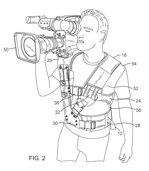
[0012] Fig. 2 illustrates a handheld professional video camera resting
unattached atop a
false shoulder of an embodiment of the present invention, as mounted on a
simulated
shoulder and torso;
[0013] Fig. 3 illustrates a second embodiment of the present invention;
[0014] Figs. 4 and 5 illustrate a third embodiment of the present invention;
[0015] Figs. 6-8 illustrate individual components of the side support
structure of the
embodiment of Figs. 4 and 5;
3
CA 03116040 2021-04-09
WO 2020/077018
PCT/US2019/055485
[0016] Fig. 9 illustrates a support part connected to the false shoulder,
allowing the rig to
support a suspended camera with a cable, elastic band, rope, or any other
support device
connected to it and
[0017] Fig. 10 illustrates a part in isolation according to Fig. 9
4
CA 03116040 2021-04-09
WO 2020/077018
PCT/US2019/055485
DETAILED DESCRIPTION
[0026] The present invention seeks to disperse the weight of a shoulder-
mounted camera
away from the back and onto the lower portion of the operator's body. For
example, in
one embodiment of the invention, much of the weight of the camera assembly is
transferred to the hips and legs. The load on the thoracic and lumbar of the
back is
reduced or eliminated, depending on the embodiment and/or the user's
preference. Most
embodiments will accommodate a variety of types and sizes of camera.
[0027] In one embodiment, an exoskeleton is created that extends over the
operator's
shoulder. A surface above the shoulder supports a camera that is typically not
attached to
the exoskeleton. In one embodiment, the structure of a camera-supporting rig
has struts
that come up one side of the body, over the shoulder, and down the other side
of the
body. The struts may be stabilized by one or more side middle straps to keep
the rig from
moving against body movement. The rig may include a mechanism for moving,
extending, and collapsing the struts. It may also have at least one movable
mid-strap to
adjust the rig to a desired height, preferably without affecting the overall
strut height.
This allows for adjustments for different body types, and also allows for
adjusting the
height of the camera-supporting surface between takes or from shot to shot.
[0028] A sliding adjustment mechanism on the back of the rig may be provided
to allow
for changing the position of the rear strut, while keeping the rest of the
system in place.
[0029] The top camera-supporting or "false shoulder" part may optionally be
made
available with a choice of different surfaces. In one embodiment, a resilient
surface
CA 03116040 2021-04-09
WO 2020/077018
PCT/US2019/055485
material is applied to the surface, for example. The resilient surface allows
for a slight
cradle for the bottom of a camera. The weight of the camera pushes down the
padded
surface, and allows for more stability by slightly grabbing sides of the
camera, for
example.
[0030] In one embodiment, there is also a slot in the top of at least one of
the struts to
allow adjustment of the camera-supporting surface of the false shoulder to
hinge slightly
towards or away from the operator, providing the operator the choice of a
desired angle
of the camera-supporting surface.
[0031] Turning now to specific exemplary embodiments, in one embodiment, as
shown
particularly in Fig. 1, a system for supporting a video recording device and
transferring
the load 10 includes a padded waist belt 12 that attaches to two main support
struts 14,
16. The waist belt may have a clasp closure 13, or other closure means known
in the art
such as, for example, a belt buckle. The belt 12 may be adjustable in size for
different
operator body types or comfort preferences. The belt may be made from any of a
variety
of materials, ranging from polymers to fabric to any other material known in
the art for
support belts. The belt may optionally be padded, as shown in Fig. 1, for user
comfort.
[0032] The struts 14, 16 rise up and meet a piece of padded, curved material
(a "false
shoulder") 18 that rests above the operator's shoulder. This false shoulder 18
may have a
base layer of a hard ridged or partially rigid plastic, carbon fiber, a
composite material, or
any suitable material. The shoulder may have an upper surface 20 on which a
camera will
rest, and an inner surface 22 which when the apparatus is mounted on the user,
generally
6
CA 03116040 2021-04-09
WO 2020/077018
PCT/US2019/055485
is situated a spaced distance above the user's actual shoulder (see Fig. 2).
In one non-
limiting embodiment, the spaced distance is just high enough to remove weight
from the
shoulder. This spacing can be adjusted by adjusting the height of one or more
of the
struts, for example, according to the operator's preference. The operator may
decide how
much contact (if any) they want between the false shoulder and their actual
shoulder.
This height adjustment can also be used to raise or lower the video/film
recording device
if the operator desires the shot to come from a higher or lower angle. In a
presently-
preferred use, the false shoulder will sit slightly above the operator's real
shoulder, just
high enough to take the weight off the shoulder, but low enough to let the
operator feel a
bit of contact with the rig, and thus the camera.
[0033] The apparatus may optionally include a strap 24 to extend around the
torso of the
user, which may have a clasp 26 or other securing means. The support struts
14, 16 may
be adjustable in height, to account for different user heights. In one
embodiment, each
support bean has a respective lower strut 28, 30 and an upper strut 32, 34.
Each
upper/lower strut combination is interconnected, with a length adjustment
mechanism 36,
38. One such mechanism as shown in Fig. 1 utilizes a series of openings and a
resilient
button (e.g. 40), which may be depressed to allow the upper and lower struts
to move
relative to one another before the button is allowed to extend through another
opening to
adjust the length. Alternatively, rather than using a resilient button, a
nut/bolt
combination may be employed. In another embodiment, the upper and lower struts
could
have horizontal ridges that line up with one another, allowing a tightening
mechanism to
7
CA 03116040 2021-04-09
WO 2020/077018
PCT/US2019/055485
hold them together, with the ridges supporting the struts together. This
tightening
mechanism could be easily opened and closed by the operator for fast
adjustments of the
length of the struts.
[0034] Referring to the embodiment of Figure 2, in use a camera 50 may rest
against the
upper surface 20 of the false shoulder. The camera 50 may optionally have, for
example,
one or more camera grips, as is common in many cases of handheld camera work,
though
not necessary or important in order to use the system for supporting a
video/film
recording device. For simplicity, Fig. 2 illustrates the torso 52 of an
imaginary user,
including an actual shoulder 54 and a waist 56, about which the belt 12
extends and to
which it is secured. In a preferred embodiment, the camera 50 is not secured
to the upper
surface 20 of the shoulder, but simply rests upon it.
[0035] The upper surface 20 may have a texture and/or be made of a material
that
prevents the camera from slipping on the surface and/or to hug the base of the
camera
slightly. By not being secured to the upper surface 50 of the false shoulder,
the camera
may be quickly set down and/or taken off of the apparatus. In one embodiment,
the top
includes a layer of leather (or similar durable fabric) covering a thin pad
atop a harder
layer of support material.
[0036] Resting atop the false shoulder, the camera 50 may be easily
repositioned, as
desired, for the desired tilt/pan/roll at a given moment. Figs. 3-6 illustrate
a prototype of
an embodiment of the present invention as it appears mounted on the upper body
of a
user.
8
CA 03116040 2021-04-09
WO 2020/077018
PCT/US2019/055485
[0037] The false shoulder may optionally be resilient and bend slightly when
weight is
applied, acting as a "shock absorber" when the operator is walking. The "shock
absorber" may optionally include more specific and targeted shock absorption,
such as by
making the support struts more flexible, and/or by including a spring-based or
hydraulic
shock absorption system or the like. The false shoulder may be able to bend
slightly when
weight is applied for the purpose of fitting different shoulder/body sizes. In
another
embodiment, both the false shoulder and the struts could be completely rigid,
and not flex
or bend at all.
[0038] In an alternative embodiment, beneath the false shoulder, there may
optionally be
a pad to allow the false shoulder to contact the user's shoulder if desired
for support or
stability. The support struts may also have small pads on the back to allow
for support
contact with the operator's chest and/or upper back. These pads could be
removable and
adjustable as to where they lay on the struts and false shoulder to allow for
maximum
comfort for the operator.
[0039] In a presently preferred embodiment, the false shoulder will hover
slightly above
the operator's real shoulder, so that weight is transferred from the shoulder
to the belt.
Typically, the belt is adequately padded, possibly with removable/addable pads
for the
user to customize, and might also include a hard plastic outer or inner
portion to which
the support struts connect. This may help spread the load as evenly as
possible on the
belt. The belt may include a quick release mechanism that is easy to
lock/unlock for fast
and simple taking on and off. For a right-handed operator, the support rods
may be
9
CA 03116040 2021-04-09
WO 2020/077018
PCT/US2019/055485
stabilized under the operator's right arm with, for example, a fabric tension
webbing that
stays tight against the operator's right rib cage, or with a harder material,
for example.
[0040] As discussed, in a presently preferred embodiment, the camera does not
attach to
the false shoulder. Instead, the camera is balanced atop the false shoulder by
the
operator, just as if it would be if the camera were on the operator's real
shoulder. The
operator is then free to pan,tilt, and/or roll the camera as if it were on
his/her shoulder.
He/she can also sit down, stand up, run, spin around, etc. as if he/she was
doing regular
handheld camerawork. Ideally, the system is compact and lightweight, so that
the
operator's movement is not hindered by a bulky apparatus.
[0041] In an alternative approach illustrated in Fig.3 , additional support
struts 214, 216
are added for heavier cameras and/or when the operator desires more support.
For
example, there may be two more support struts 214, 216 that connect to the
false shoulder
at or near the points that the main two support struts connect, at or near the
false
shoulder. These extra two struts 214, 216 serve to spread the weight out even
more to the
front left and back left of the belt. In a preferred embodiment, all four
support struts 114,
116, 214, 216 have upper and lower struts, and can adjust length via length
adjustment
mechanisms 136, 138, 236, 238 that adjust, then lock into place to accommodate
different
camera weights, desired camera height, and operator body types. In one
embodiment, the
additional support struts may be added and removed by the user, to spread the
wear and
tear on an operator's body throughout the working day, as well as to allow the
operator to
add or remove supports based on the desired shot and body position needed.
CA 03116040 2021-04-09
WO 2020/077018
PCT/US2019/055485
[0042] While the presently-preferred application is to assist camera
operators, the
apparatus could also be applied to non-camera related work. Weight that is
normally
carried on a shoulder is transferred to the user's hips/legs. For example,
construction
workers may use the apparatus in carrying heavy objects such as a bag of
cement or
heavy construction material, to reduce the risk of back injury at work.
[0043] Various further modifications may be made, either alone or in
combination with
other optional features. The support struts could attach to the belt in a way
that allows for
quick and easy adjustment to the portion of the belt they connect with. The
user could
slide the struts left or right along the belt for user comfort and to
accommodate different
body sizes and types. After being adjusted they would be locked into place via
a quick
locking/unlocking mechanism. Alternatively, there could be multiple holes
along the
sides of the belt that accept screws to secure the support struts, but would
allow the
support struts to still be moved side to side along the belt.
[0044] Another optional feature is that additional support struts beyond two
could be
made of fabric (nylon or another suitable material) straps or webbing that are
connected
to the primary support struts and the belt in the same positions as
illustrated with the
additional support struts. These straps would be more flexible and quickly
tightened/lengthened than the rigid support struts, and allow for a lighter
overall weight
of the apparatus.
[0045] In another embodiment, the false shoulder could include a lengthening
mechanism to adjust to different operator's body types. There could be a
sliding and
11
CA 03116040 2021-04-09
WO 2020/077018
PCT/US2019/055485
locking mechanism in the middle of the false shoulder, for example, allowing
the user to
slide the front and back of the false shoulder apart or closer together, and
then lock it in
place. This would be adjustable from the bottom of the false shoulder, on top
of the
optional pad, where the pad would hide this mechanism when not in use. In an
adjustable
embodiment, the top of the false shoulder would have two surfaces, one
directly on top of
the other, which would slide flush, in order to revise without causing a bulge
on the top
surface when adjusted.
[0046] In a further alternative embodiment, both the front and back struts are
wider
overall, roughly 2.5" wide as one non-limiting example. The top of these
vertical
structures will flare out to 5", for instance, to mount the curved shoulder
plate. The
bottom will also flare out where it is attached to the belt. The back strut is
adjustable as
to where it sits on the belt to allow for customization to different body
types. The rear
vertical structure base will have a continual horizontal adjustment +/- 4" for
waist size
adjustment relative to the front plate. There are removable pads that the
operator can
Velcro on the backs of both struts to fit between the structure and their body
to provide
padding, if desired. These struts both have two adjustable nobs that control
the height
adjustment of the struts.
[0047] In this embodiment, there is a piece of metal that sits in between the
top and
bottom metal plates that make up the strut. When the nobs are loosened, this
middle
metal plate is loosened, allowing the user to shorten or lengthen the strut,
and tighten it
12
CA 03116040 2021-04-09
WO 2020/077018
PCT/US2019/055485
back again at the desired length. The top and bottom parts that make up the
vertical struts
are slotted to allow this to slide up and down.
[0048] The midriff webbing strap may be wider and have slotted sliding plates
and be
adjustable via tri-glides to accommodate the size of the upper torso. There
may be a
shoulder strap that fits over the operator's left shoulder for added weight
support and to
help keep the rig in place relative to the operator's body. This is made of
textured nylon
and space mesh, and is removable through quick releases both in the front and
back.
[0049] Non-limiting examples of materials for the waist belt include textured
nylon and
polyester spacer mesh- 5" width with 1/8" and 1/16" polypropylene, 1" webbing
to
contain belt- horizontal 1/2" bubbled accessory webbing, and buckle hardware.
The
waist belt may be 5" wide, for example, and come in different sizes (small,
medium and
large, for instance). Accessory webbing loops may be on the belt, to allow the
user to
clip things like a phone case, walkie talkie, or other accessory to the belt.
[0050] The curved shoulder support "false shoulder" plate may have a heavy
saddle
leather surface, for example. Optionally, it may also include a crescent
shaped cut-out to
accommodate the operator's neck. The camera-supporting surface may also
include a side
to side tilt adjustment. The foregoing features of this alternative embodiment
may be
implemented either alone or in combination as described.
[0051] Considering now an additional embodiment, Figs. 4 and 5 illustrate
another
embodiment that has upper struts 232, 234 and lower struts 228, 230 that slide
relative to
one another to adjust the height of a false shoulder 218, on which a camera
will rest
13
CA 03116040 2021-04-09
WO 2020/077018
PCT/US2019/055485
without being secured to the false shoulder. In this embodiment, the false
shoulder 218
includes a padded upper surface 220. The pad may be secured to the false
shoulder
structure 219 via hook-and-loop material such as Velcro. A variety of pads of
different
materials, stiffnesses, and dimensions may be provided. A variety of pads may
also be
provided for the inner surface 222 of the false shoulder and selectively
attached with
hook-and-loop material or other attachment means.
[0052] The false shoulder structure 219 is typically a molded polymer, such as
ABS
plastic for example, that may flex somewhat when a camera is placed atop the
padded
upper surface 220. The false shoulder structure may have a thickness selected
by the
designer for specific camera weights, desired flexibility, and/or other design
factors.
[0053] The false shoulder structure 219 is secured to upper struts 232 and
234,
respectively, with nut-and-bolt fasteners 223, 225 or other suitable
fasteners. At least one
slot may be provided in conjunction with at least one fastener. For example,
slot 227
permits the location of fastener 223 to be adjusted, so that the false
shoulder 218 may be
tilted, as desired. The tilt may effect the angle at which the camera is
directed.
[0054] As seen, the upper struts 232, 234 have relatively narrow neck portions
that flair
outwardly to form a wider upper portion at which the false shoulder 218 is
bolted to the
upper struts.
[0055] The assembly also includes lower struts 228, 230, which are separate
pieces from
upper struts 232, 234. Fig. 6 illustrates an upper strut 232 in isolation. In
this
embodiment, the strut is about 5 inches at its widest, and about 2 1/2 inches
at its long
14
CA 03116040 2021-04-09
WO 2020/077018
PCT/US2019/055485
neck. The central slot is approximately 11 inches long and may be from 1/4
inch to 3/4 inch
wide.
[0056] Fig. 7 illustrates a lower strut 228 in isolation. In this embodiment,
the lower strut
is about 16 inches long, with a slot of approximately 8 inches. The neck
portion may be
about 10.5 inches long, with the wider base being about 5.5 inches in total
length and 6
inches at its widest point. Oh course, other dimensions may be used, depending
on the
design.
[0057] Fig. 8 illustrates a torso strap plate 250 in isolation. The torso
plate includes slots
through which the strap may loop, each slot being approximately 3 inches in
diameter,
with the ear through which the slots extend being approximately 3/4 inch in
width. The
main body of the plate is approximately 2 1/2 inches wide, with the plate
being about 4 1/2
inches long.
[0058] Referring back to Fig. 5, each of the upper struts 232, 234 has a
respective
longitudinal slot, and each of the lower struts 228, 230 has a corresponding
longitudinal
slot. Adjustment knob assemblies 256 and 258 interconnect the upper and lower
struts,
through the respective slots. When the adjustment knobs are loosened, the
upper strut is
free to slide relative to the lower strut. This permits the false shoulder to
be raised or
lowered, as desired. So, for example, with the knobs loosened, the upper strut
may slide
toward or away from the lower strut, thereby increasing or decreasing the
overall length
of the strut structure.
CA 03116040 2021-04-09
WO 2020/077018
PCT/US2019/055485
[0059] A torso strap plate 250 can also slide relative to the lower and upper
struts, to
adjust the height of the torso strap 224. The torso strap plate 250 also
includes strap
supports 252 and 254, through which torso strap 224 may be threaded and
secured. When
the user has adjusted the height of the false shoulder 218 to the desired
height, and has
adjusted the torso strap plate 250 to a desired height, the knobs are turned
to tighten and
to lock the pieces in place. Women, for example, can adjust the mid-rift strap
above or
below their chest for desired comfort by adjusting the torso plate 250 higher
or lower in
terms of where it sits on the struts. This can be done without affecting the
height of the
false shoulder.
[0060] Lower left struts 228, 230 each have a lower attachment plate. In Fig.
5, lower
attachment plate 260 attaches to the reinforced waist belt 212. The waist belt
212
includes a molded polymer frame, typically polypropylene as one example,
covered with
foam padding. The thickness of the molded polymer may be chosen for desired
structural
properties. The molded polymer may include threaded eyelets embedded therein
through
which a bolt/nut assembly may be secured. Consequently, Fig. 5 illustrates
lower
attachment plate 260 bolted and secured to reinforced waist belt 212.
[0061] Fig. 5 illustrates rivets 264. These are rivets that secure both sides
of the padding
to the interior support frame. The rivets help maintain the shape of the waist
belt as
weight is applied to it, and prevents the padding and interior support frame
from
separating.
16
CA 03116040 2021-04-09
WO 2020/077018
PCT/US2019/055485
[0062] As seen, the waist belt includes a clasp, the length of which can be
adjusted.
Similarly, the torso strap may be adjustable in length. Various other pads may
be
provided, such as for placing on the inside of the struts or elsewhere on the
apparatus. A
reverse coil zipper may be used at the waist, to not dig into the operator's
waist. Various
hardware may be optionally secured to the belt, with a securing portion of the
hardware
going all the way through the hard plastic inner structure, anchoring
everything to it to
keep the material from sliding/rotating on/around the inner harder structure
of the belt
when weight is put on the rig, and pressing down against an operator's body.
(see, e.g.,
eyelets 264 on Fig 5).
[0063] The system may include a belt extension option. A removeable/addable
portion
of the belt that can slide on the existing main nylon strap on the belt when
it is extended
longer than the existing belt. So, for example, a floating extra 5" or so
piece of belt can
be added if needed for more padding when the belt is extended for a larger
user.
[0064] Many camera operators often shoot with an "underslung" camera,
essentially
cradling it by their side to shoot from a lower angle. It can be dangerous to
hold a heavy
camera like that, so a support system can help prevent bodily injury.
[0065] One alternative embodiment includes a plate 400 (Figs. 9 and 10) or
other support
part connected to the false shoulder that would allow the rig to support a
suspended
camera, with similar weight transfer principals. This part (e.g. 400) could be
added on
and removable, or part of the false shoulder itself It would function to have
a cable,
elastic band, rope, or any other support device connect to it, with a camera
connected on
17
CA 03116040 2021-04-09
WO 2020/077018
PCT/US2019/055485
the opposite side. The top side is connected to the false shoulder directly
(Fig. 9), or to a
point that is offset from the false shoulder either to the side, or higher, or
lower -
wherever the operator desires their camera to be connected. In one embodiment,
a plate
roughly 6" long with a roughly 3/4" hole connects to the false shoulder and
provides a
hole that an elastic band can pass through.
[0066] In a different embodiment, there could be a riser attached that serves
to bring the
point from which the camera is suspended higher, above an operator's shoulder
for
example. Alternately, in another embodiment, an adapter could be used to bring
the pick
point lower.
[0067] In view of the many possible embodiments to which the principles of the
disclosed invention may be applied, it should be recognized that the
illustrated
embodiments are only preferred examples of the invention and should not be
taken as
limiting the scope of the invention.
18