Note: Descriptions are shown in the official language in which they were submitted.
CA 03116205 2021-04-12
WO 2020/106556
PCT/US2019/061613
DIELECTRIC SPECTROSCOPY SENSING APPARATUS AND METHOD OF
USE
BACKGROUND
[0001]
Dielectric spectroscopy (DS) has been described as a useful analytical
tool in the biomedical field as a label-free, non-destructive and real-time
method
to study the interaction of RF/microwave fields with biological/biochemical
samples while requiring minimal sample preparation. Molecular characteristics
of
biomaterials such as human blood, spinal fluid, breast tissue and skin have
been
studied using DS for applications in disease detection and clinical diagnosis.
Typical DS systems, however, tend to be large and expensive, making them cost-
prohibitive in certain circumstances.
[0002] US
9,995,701 B2 describes a DS system including a sensor having an
input configured to receive an input radio frequency (RF) signal and an output
to
provide an output RF signal to an analyzer device. The sensor also includes
substantially co-planar first and second sensing electrodes and a floating
electrode. The first sensing electrode is coupled to the input and the second
sensing electrode is coupled to the output. The floating electrode is spaced
apart
from the sensing electrodes by a space that defines a fluid channel that is
communicatively coupled to receive a fluid material via a fluid port.
[0003]
Improvements can be made in the aforementioned DS system to make
the system more intuitive and user friendly.
SUMMARY
[0004] In view
of the foregoing, a DS sensing apparatus includes a body
defining a test volume between a first surface and an opposing second surface
spaced from the first surface a distance that allows a fluid to enter the test
volume from a fluid inlet, which is communicatively coupled to the test
volume,
via capillary action. The electrodes provided on the body include a first
sensing
electrode on the first surface and configured to receive an input radio
frequency
(RF) signal, a second sensing electrode on the first surface spaced from the
first
sensing electrode and configured to deliver an output RF signal and a floating
electrode on the second surface.
1
CA 03116205 2021-04-12
WO 2020/106556
PCT/US2019/061613
BRIEF DESCRIPTION OF THE DRAWINGS
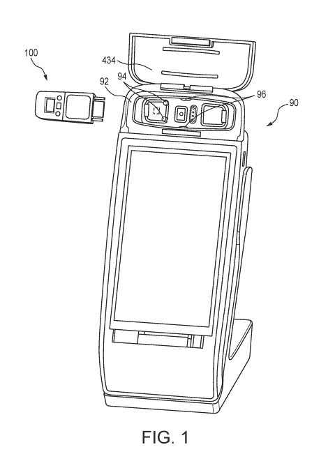
[0005] FIG. 1 is a perspective view of a DS sensing apparatus and an
analyzer device.
[0006] FIG. 2 is a perspective view of the DS sensing apparatus depicted in
FIG. 1.
[0007] FIG. 3 is a plan view of the DS sensing apparatus depicted in FIG.
1.
[0008] FIG. 4 is a side view of the DS sensing apparatus depicted in FIG.
1.
[0009] FIG. 5 is an exploded perspective view of the DS sensing apparatus
depicted in FIG. 1.
[0010] FIG. 6 is another exploded perspective view of the DS sensing
apparatus depicted in FIG. 1.
[0011] FIG. 7 is a disassembled plan view of the DS sensing apparatus
depicted in FIG. 1.
[0012] FIG. 8 is another disassembled plan view of the DS sensing apparatus
depicted in FIG. 1.
[0013] FIG. 9 is a plan view of the DS sensing apparatus and a analyzer
device according to another aspect of the present disclosure.
[0014] FIG. 10 is an exploded perspective view of a DS sensing apparatus
according to another aspect of the present disclosure.
[0015] FIG. 11 is another exploded perspective view of the DS sensing
apparatus of FIG. 10.
[0016] FIG. 12 is a cross-sectional side view of the DS sensing apparatus
of
FIG. 10.
[0017] FIG. 13 is an enlarged partial view of the DS sensing apparatus of
FIG.
12.
[0018] FIG. 14 is a flex circuit incorporated in the DS sensing apparatus
according to another aspect of the present disclosure.
[0019] FIG. 15 is a flex circuit incorporated in the DS sensing apparatus
according to another aspect of the present disclosure.
[0020] FIG. 16 is a flex circuit incorporated in the DS sensing apparatus
according to another aspect of the present disclosure.
[0021] FIG. 17 is a flex circuit incorporated in the DS sensing apparatus
according to another aspect of the present disclosure.
2
CA 03116205 2021-04-12
WO 2020/106556
PCT/US2019/061613
[0022] FIG. 18
is a flex circuit incorporated in the DS sensing apparatus
according to another aspect of the present disclosure.
[0023] FIG. 19
is a partial, cross-sectional view of the DS sensing apparatus
according to another aspect of the present disclosure.
[0024] FIG. 20
is a partial, cross-sectional view of the DS sensing apparatus
according to another aspect of the present disclosure.
[0025] FIG. 21
is a partial, cross-sectional view of the DS sensing apparatus
according to another aspect of the present disclosure.
[0026] FIG. 22
is a partial, cross-sectional view of the DS sensing apparatus
according to another aspect of the present disclosure.
[0027] FIG. 23
is a schematic cross-sectional view of the body of the DS
sensing apparatus according to another aspect of the present disclosure.
[0028] FIG. 24
is a schematic cross-sectional view of the body of the DS
sensing apparatus according to another aspect of the present disclosure.
[0029] FIG. 25
is a schematic cross-sectional view of the DS sensing
apparatus according to another aspect of the present disclosure.
[0030] FIG. 26
is a schematic cross-sectional view of the DS sensing
apparatus according to another aspect of the present disclosure.
[0031] FIG. 27
is a schematic cross-sectional view of the DS sensing
apparatus according to another aspect of the present disclosure.
[0032] FIG. 28
is a perspective view of the body of the DS sensing apparatus
according to another aspect of the present disclosure.
[0033] FIG. 29
is a perspective view of the body of the DS sensing apparatus
according to another aspect of the present disclosure.
[0034] FIG. 30
is a plan view of a DS sensing apparatus according to another
aspect of the present disclosure with a lid in an open position.
[0035] FIG. 31
is a perspective view of the DS sensing apparatus of FIG. 30
with the lid in an open locked position.
[0036] FIG. 32
is a plan view of the DS sensing apparatus of FIG. 30 with the
lid in a closed position.
[0037] FIG. 33
is a partial perspective view of the DS sensing apparatus of
FIG. 30 with the lid in the open locked position.
[0038] FIG. 34
is a perspective view of the DS sensing apparatus of FIG. 30
with the lid in the closed position.
3
CA 03116205 2021-04-12
WO 2020/106556
PCT/US2019/061613
[0039] FIG. 35
is an exploded perspective view of the DS sensing apparatus
of FIG. 30.
[0040] FIG. 36
is a perspective view of the DS sensing apparatus of FIG. 30
with the lid in the open locked position.
DETAILED DESCRIPTION
[0041] It
should, of course, be understood that the description and drawings
herein are merely illustrative and that various modifications and changes can
be
made in the structures disclosed without departing from the present
disclosure. Referring now to the drawings, wherein like numerals refer to like
parts throughout the several views,
[0042] FIG. 1
illustrates an analyzer device 90 including a housing 92 with
pogo pins 94 and mating features 96 corresponding with a DS sensing apparatus
100. The analyzer device 90 is configured for receiving the DS sensing
apparatus 100 in the housing 92, and connecting to the DS sensing apparatus
100 in a circuit via the pogo pins 94. FIGS. 2 ¨ 8 illustrate the DS sensing
apparatus 100 including a body 102 having a first body end portion 104 and a
second body end portion 110. The DS sensing apparatus 100 includes a cap
112 that cooperates with the first body end portion 104 and the second body
end
portion 110. The body 102 is made from an upper body 114, a lower body 120,
and a spacer 122 is interposed between the upper body 114 and the lower body
120 and connecting the upper body 114 with the lower body 120.
[0043] As
depicted in FIGS. 2 and 4 ¨6, the upper body 114 includes cut-outs
124 disposed between the first body end portion 104 and the second body end
portion 110 that align with the mating features 96 of the analyzer device 90.
In
this manner, the cut-outs 124 and the mating features 96 are configured to
ensure proper alignment between the DS sensing apparatus 100 and the
analyzer device 90 when the DS sensing apparatus 100 is inserted into the
analyzer device 90. Additionally, the cut-outs 124 each provide a gripping
section for convenient handling by a user.
[0044] The
spacer 122 is interposed between a first surface 130 defined by
the lower body 120, and a second surface 132 defined by the upper body 114
and spaced from the first surface 130. The spacer 122 has a thickness that
defines the spacing between the first surface 130 and the second surface
4
CA 03116205 2021-04-12
WO 2020/106556
PCT/US2019/061613
132. The spacer 122 thickness is 200 ¨ 300 microns, and according to at least
one embodiment, the spacer 122 thickness is 250 microns. The 250 micron
spacer 122 may include a tolerance in thickness of 10 percent (i.e. 25
microns).
The spacer 122 includes a first spacer surface 134 that is planar and a second
spacer surface 140 that is planar. When the DS sensing apparatus 100 is
assembled, the first spacer surface 134 contacts the first surface 130, and
the
second spacer surface 140 contacts the second surface 132. According to at
least one embodiment, the spacer 122 is a double-sided adhesive tape.
[0045] As
depicted in FIGS. 5 ¨ 8, a first assembly pin 142 and a first
assembly hole 144 are provided on the first surface 130, disposed on the body
102 of the lower body 120. A first assembly aperture 150 defined by the spacer
122 is located to receive the first assembly pin 142 therethrough when the
upper
body 114 and the lower body 120 are assembled. A second assembly pin 152
and a second assembly hole 154 corresponding to the first assembly pin 142 and
the first assembly hole 144 are provided on the second surface 132 and
disposed
on the body 102 of the lower body 120. A second assembly aperture 160 defined
by the spacer 122 is located to receive the second assembly pin 152
therethrough when the upper body 114 and the lower body 120 are assembled.
The assembly pins 128, 152 and assembly holes 144, 154 are configured
respectively to snap together when the upper body 114 and the lower body 120
are assembled. Once the assembly pins 128, 152 and assembly holes 144, 154
are snapped together, a user cannot disassemble the lower body 120 and upper
body 114 without damaging a portion of the DS sensing apparatus 100. In an
embodiment, the upper body 114 and the lower body 120 are respectively fixed
to the spacer 122 using at least one solvent weld. In an alternative
embodiment,
the upper body 114 and lower body 120 are fixed directly to each other using
at
least one solvent weld. One having ordinary skill in the art would appreciate
that
the same locking relationship between the assembly pins 128, 152 and
corresponding assembly holes 144, 154 could be achieved by switching, or
otherwise relocating the assembly pins 128, 152 and corresponding assembly
holes 144, 154 about the first and second surfaces 130, 132.
[0046] As
depicted in FIGS. 2 ¨ 5, a buckle 162 provided at the first body end
portion 104 of the lower body 120 includes a first lower finger 164, a second
lower finger 170, and a lower support 172. The buckle 162 further includes a
first
CA 03116205 2021-04-12
WO 2020/106556
PCT/US2019/061613
upper finger 174, a second upper finger 180, and an upper support 182
extending
from the upper body 114. The first lower finger 164 and the second lower
finger
170 are each spaced from, and provided on opposite sides of the lower support
172. The first lower finger 164 and the second lower finger 170 are configured
to
deflect towards the lower support 172 when pushed toward the lower support
172. The first upper finger 174 and the second upper finger 180 are each
spaced
from, and provided on opposite sides of the upper support 182. The first upper
finger 174 and the second upper finger 180 are configured to deflect towards
the
upper support 182 when pushed toward the lower support 172.
[0047] A first
protuberance 184, a second protuberance 190, a third
protuberance 192, and a fourth protuberance 194 are disposed on the first
lower
finger 164, second lower finger 170, first upper finger 174 and second upper
finger 180 respectively. The protuberances 184, 190 disposed on the first
lower
finger 164 and the second lower finger 170 extend in a direction opposite from
the lower support 172, and the protuberances 184, 190 disposed on the first
upper finger 174 and the second upper finger 180 extend in a direction
opposite
from the upper support 182.
[0048] The cap
112 includes a first cap side wall 200 that defines a first cap
opening 202 and a second cap side wall 204 that defines a second cap opening
210. Each of the first cap opening 202 and the second cap opening 210 is
configured to receive two of the first, second, third, and fourth
protuberances 184,
190, 192, 194 when the cap 112 is connected with the first body end portion
104,
thereby locking the cap 112 in a fixed position relative to the body 102.
Notably,
the cap 112 is reversible with respect to the first body end portion 104, such
that
each of the first cap opening 202 and second cap opening 210 are configured to
receive either the first and third protuberances 184, 192 or second and fourth
protuberances 190, 194. In this manner, the cap 112 may engage the first body
end portion 104 in two orientations distinguished by a 180 degree rotation of
the
cap 112 with respect to the first body end portion 104. To remove the cap 112
from the fixed position with the first body end portion 104, the protuberances
184,
190, 192, 194 are pushed inwards, out of the receiving cap openings 202, 210,
thereby unlocking the cap 112 from the fixed position. As the protuberances
184,
190, 192, 194 are pushed out of the cap openings 202, 210, the fingers 164,
170,
174, 180 deflect toward the supports 172, 182, and the fingers 164, 170, 174,
6
CA 03116205 2021-04-12
WO 2020/106556
PCT/US2019/061613
180 are configured to retract to an undeflected position further away from the
supports 172, 182 when not pushed inwards. In this manner, once connected,
the cap 112 and the first body end portion 104 are configured to be
disassembled
without damaging any portion of the DS sensing apparatus 100.
[0049] As
depicted in FIGS. 2 ¨ 8, the second body end portion 110 is
provided on an opposite end of the body 102, in a direction opposite from the
first
body end portion 104. The second body end portion 110 includes a fluid inlet
212
defined by a cantilever portion including a first fin 214 and a second fin 220
extending from the body 102 as part of the second body end portion 110. More
specifically, the cantilever portion extends from a pedestal surface 222 that
is
offset from a ledge surface 224. The first fin 214 is integrally formed from
the
upper body 114 and extends the first surface 130 defined by the upper body
114,
and the second fin 220 is integrally formed from the lower body 120 and
extends
the second surface 132 defined by the lower body 120. Both the pedestal
surface 222 and the ledge surface 224 reside in respective planes that are
normal to the direction in which the fins 214, 220 extend from the pedestal
surface 222.
[0050] The
pedestal surface 222 and the fins 214, 220 define a neck down
portion 230. More specifically, each of the first fin 214 and the second fin
220
respectively includes a first side edge 232, 234 and a second side edge 240,
242
disposed inwards of an outer edge 244 of the pedestal surface 222. In this
manner, as shown in FIG. 2, the first fin 214 and the second fin 220 define
the
fluid inlet 212 that has a thinner front view profile than the pedestal
surface 222
and the ledge surface 224.
[0051] The
first surface 130 and the second surface 132 are spaced from
each other such that the fins 214, 220 define a test volume 250 which fluid
enters
via capillary action from the fluid inlet 212, which is communicatively
coupled to
the test volume 250. The test volume 250 is less than 18 pL, and in accordance
with at least one embodiment of the DS sensing apparatus 100, the test volume
is about 9 pL. The fluid inlet 212 and test volume 250 are configured such
that
fluid entering the fluid inlet 212 and the test volume 250 via capillary
action is
drawn without a wicking element. Instead, the capillary action driving fluid
flow is
facilitated by the spacing between the upper body 114 and the lower body 120.
7
CA 03116205 2021-04-12
WO 2020/106556
PCT/US2019/061613
[0052] As
depicted in FIGS. 2, 4, and 5, the first fin 214 includes a first
peripheral edge 252 that is angled from a first outer surface 254, toward the
first
surface 130 and the fluid inlet 212. The second fin 220 similarly includes a
second peripheral edge 260 that is angled from a second outer surface 262
toward the second surface 132 and the fluid inlet 212.
[0053] The
fluid inlet 212 in the illustrated embodiment is configured to receive
fluid along the peripheral edges 252, 260 of the fins 214, 220. With reference
to
FIG. 4, the peripheral edges 252, 260 form a "less than" symbol ("<") shape
taken
from a side view of the body 102. This configuration allows a user of the DS
sensing apparatus 100 to prick his/her skin, for example at one's finger, to
deposit a droplet of blood between the first peripheral edge 252 and the
second
peripheral edge 260, which will then be drawn into the test volume 250, which
obviates the need for a pipette or dropper to load the test volume 250 with a
fluid
to be tested. As shown in FIG. 3, the test volume 250 is generally rectangular
when taken from a front view. As shown in FIGS. 3 and 4, the peripheral edges
252, 260 and side edges 232, 234, 240, 242 of the fins 214, 220 provide a
rectangular test volume 250 that is open to ambient air when the cap 112 is
not
placed on the body 102.
[0054] When the
fins 214, 220 take configurations other than rectangular, the
peripheral edges 252, 260 can also take configurations other than linear.
Also,
the profile of each peripheral edge 252, 260 can be one of (1) a chamfer,
which is
shown in FIGS. 2, 4, and 5, (2) a radius, or (3) a combination of a chamfer
and a
radius. Also, indicia 264 such as frosting (stippled region in FIG. 3) on the
fins
214, 220 can provide opaque or translucent sections that outline the test
volume
250 and provide a location for a user to target a blood droplet. For example,
as
shown in FIG. 2, the test volume 250 is outlined by a visibly clear section
270
configured to provide visual indication to a user when fluid resides in a test
volume 250.
[0055] As shown
in FIGS. 3 and 5 ¨ 8, electrodes, or at least portions thereof,
reside in the test volume 250 to allow DS testing to be undertaken on the
fluid
within the test volume 250. After the fluid is loaded into the test volume 250
and
the cap 112 is closed, the DS sensing apparatus 100 is configured to be
inserted
into the analyzer device 90 so that DS testing can be performed on the fluid
within the test volume 250.
8
CA 03116205 2021-04-12
WO 2020/106556
PCT/US2019/061613
[0056] A first
sensing electrode 272 and a second sensing electrode 274 are
provided on the second surface 132 of the upper body 114 and extend from a
respective first terminal end 280, 282 located on the second surface 132
within
the test volume 250 to a respective second terminal end 284, 290 that is
located
on an opposite side of the pedestal surface 222. An adhesive is deposited
between the spacer 122 and the first surface 130, and between the spacer 122
and the second surface 132 such that when fluid is provided in the test volume
250, the fluid is precluded from traveling between the spacer 122 and the
first
surface 130, and the spacer 122 and the second surface 132. With this
construction, the sensing electrodes 272, 274 are deposited, e.g. printed onto
the
second surface 132 in such a manner that when covered by the spacer 122,
which has adhesive deposited thereon, fluid in the test volume 250 is
precluded
from traveling beyond the pedestal surface 222 toward the second terminal ends
284, 290 of the respective sensing electrodes 272, 274. A floating electrode
292
is provided on the first surface 130 of the lower body 120 and is spaced from
the
sensing electrodes 272, 274 across the test volume 250. Each of the sensing
electrodes 272, 274 and the floating electrode 292 can be an electrically
conductive material (e.g., gold, copper or aluminum) deposited on the
appropriate
surface by, for example, sputter deposition using a shadow mask and lift-off
process. In such an embodiment, each of the sensing electrodes 272, 274 and
the floating electrode 292 can be formed with a thickness of 25 microns or
less.
[0057] As shown
in FIGS. 5 and 6, the spacer 122 includes pin apertures 294,
300 that correspond with the second terminal ends 284, 290 of the sensing
electrodes 272, 274 and pin openings 302, 304 of the upper body 114 when the
spacer 122 is assembled with the upper body 114, exposing the second terminal
ends 284, 290 to an exterior of the DS sensing apparatus 100 accessible to the
analyzer device 90. As shown in FIGS. 2, 3, and 5, the second body end portion
110 of the upper body 114 defines the pin openings 302, 304 disposed between
the pedestal surface 222 and the ledge surface 224. The pin openings 302, 304
align with the pin apertures 294, 300, respectively, in the spacer 122 when
the
spacer 122 is positioned on the upper body 114.
[0058]
Connector or pogo pins 94 of the analyzer device 90 can extend
through the pin openings 302, 304 and the pin apertures 294, 300 to provide
for
an electrical connection with the second terminal ends 284, 290 of the
respective
9
CA 03116205 2021-04-12
WO 2020/106556
PCT/US2019/061613
sensing electrodes 272, 274 and provide the appropriate input and output RF
signals to the sensing electrodes 272, 274 which is described in more detail
in
US 9,995,701 B2. Specifically, the first sensing electrode 272 on the second
surface 132 is configured to receive an input RF frequency signal and the
second
sensing electrode 274 on the second surface 132, spaced from the first sensing
electrode 272, is configured to deliver an output RF signal. When a sample is
analyzed, the input RF signal bridges the test volume 250 through the sample,
connecting the floating electrode 292 on the first surface 130 to the first
sensing
electrode 272 and the second sensing electrode 274 in a circuit.
[0059] As shown
in FIGS. 2 - 6, the second body end portion 110 includes a
first locking mechanism 310 integrally formed from the first outer surface 254
between the pedestal surface 222 and the ledge surface 224 of the lower body
120. The second body end portion 110 further includes a second locking
mechanism 312 integrally formed from the second outer surface 262 between the
pedestal surface 222 and the ledge surface 224, and further located between
the
pin openings 302, 304.
According to one embodiment, the first locking
mechanism 310 and the second locking mechanism 312 are integrally formed
from the upper body 114 and the lower body 120, respectively.
[0060] Each of
the first locking mechanism 310 and the second locking
mechanism 312 are shaped as a wedge having a sloped face 314, 320 adjacent
to the second body end portion 110, with each wedge shape pointing toward the
test volume 250. The first and second locking mechanisms 310, 312 each
respectively include a substantially vertical face 322, 324 adjacent to the
respective sloped face 314, 320. The
sloped faces 314, 320 and the
substantially vertical faces 322, 324 respectively meet to form outward
pointing
edges 330, 332. The first and second locking mechanisms 310, 312 each
respectively include two lateral faces 334, 340, 342, 344 disposed between the
sloped faces 314, 320 and substantially vertical faces 322, 324. The sloped
faces 314, 320, substantially vertical faces 322, 324, and lateral faces 334,
340,
342, 344 together respectively form the wedge shapes defining the first and
second locking mechanisms 310, 312.
[0061] As shown
in FIGS. 2, 3, 5, and 6, the cap 112 defines a first notch 350
within an upper cap wall 352 and a second notch 354 within a lower cap wall
360.
As the cap 112 is connected with the second body end portion 110, inner
CA 03116205 2021-04-12
WO 2020/106556
PCT/US2019/061613
surfaces 362, 364 of the upper cap wall 352 and lower cap wall 360
respectively
slide over the sloped faces 314, 320 of the first locking mechanism 310 and
the
second locking mechanism 312. Each notch 350, 354 is capable of receiving
either the first locking mechanism 310 or the second locking mechanism 312
when the cap 112 connects with the second body end portion 110. Once the
locking mechanisms 310, 312 have engaged the notches 350, 354, the inner
surfaces 362, 364 of the upper cap wall 352 and the lower cap wall 360 are
unable to pass over the edges 330, 332 to disconnect the cap 112 from the
second body end portion 110. In this manner, both the first locking mechanism
310 and the second locking mechanism 312 are configured to engage either the
first notch 350 or the second notch 354 in a locked position. Once in the
locked
position with either the first notch 350 or the second notch 354, neither the
first
locking mechanism 310 nor the second locking mechanism 312 can be removed
from the receiving notch 350, 354 without damaging a portion of the DS sensing
apparatus 100. As a result, once the cap 112 is connected with the second body
end portion 110, the cap 112 cannot be removed from the second body end
portion 110 without damaging the DS sensing apparatus 100. One having
ordinary skill in the art would appreciate that the same locking relationship
between the cap 112 and the second body end portion 110 can be achieved by
switching the locations of the first locking mechanism 310 and the second
locking
mechanism 312 with the locations of the first notch 350 and the second notch
354, respectively.
[0062] The cap
112 features pin holes 370, 372 defined within the upper cap
wall 352, and pin holes 374, 380 defined within the lower cap wall 360. The
pin
holes 370, 372, 374, 380 are configured to receive the pogo pins 94 of the
analyzer device 90, allowing the analyzer device 90 to access the pin openings
302, 304 when the cap 112 is assembled with the second body end portion 110.
The pin holes 370, 372 on the upper cap wall 352 are coaxial with the pin
holes
374, 380 on the lower cap wall 360. As a result, the cap 112 is reversible
about
the second body end portion 110, i.e. the cap 112 may engage the second body
end portion 110 in two orientations distinguished by a 180 degree rotation of
the
cap 112 with respect to the second body end portion 110, and in each position
the pin openings 302, 304 are accessible by the pogo pins 94.
11
CA 03116205 2021-04-12
WO 2020/106556
PCT/US2019/061613
[0063] As shown
in FIGS. 2 ¨ 6, the second body end portion 110 includes a
gasket 382 disposed around the periphery of the second body end portion 110,
located between the pin openings 302, 304 and the test volume 250. More
specifically, the gasket 382 is located between the pin openings 302, 304 and
the
pedestal surface 222. When the cap 112 is assembled with the second body end
portion 110, the cap 112 is disposed over the test volume 250, and the gasket
382 and the cap 112 form a liquid-tight seal such that fluid deposited at the
fluid
inlet 212 cannot pass over the gasket 382 toward the pin openings 302, 304. As
a result, the liquid-tight seal prevents contamination of the pin openings
302, 304
by fluid in the test volume 250 when the cap 112 is connected with the second
body end portion 110. Additionally, the cap 112 and the liquid-tight seal
together
are configured to close the second body end portion 110 from ambient air when
the cap 112 is connected with the second body end portion 110, thereby
preventing air from entering the test volume when the cap 112 is connected
with
the second body end portion 110. A liquid-tight seal can also be achieved, for
example, by plastic-to-plastic contact between the cap 112 and the second body
end portion 110.
[0064] As shown
in FIGS. 2, 3, and 5 ¨ 8 the DS sensing apparatus 100 may
include a heating system configured for heating the test volume 250, including
the sensing electrodes 272, 274 and test sample a (not shown), to a
predetermined temperature. The heating system of the DS sensing apparatus
100 may be configured to heat the test volume 250 to 37 C 0.5 C within 30
seconds. In another embodiment, the test volume 250 may be heated to 37 C
0.5 C within 60 seconds. As shown in FIGS. 5 ¨ 8, the DS sensing apparatus
100 heating system includes a support 384 that is a circuit support, which is
a
printed circuit board (PCB) in the depicted embodiment, provided between the
upper body 114 and the lower body 120. More specifically, the support 384 is
interposed between the upper body 114 and the spacer 122. A first support
surface 390 is planar and contacts the second spacer surface 140. The support
384 is disposed within the body 102, including a first support end portion 392
disposed toward the first body end portion 104, and a second support end
portion
394 extending in an opposite direction and toward the second body end portion
110. The second support end portion 394 extends into the second body end
portion 110, terminating before reaching the gasket 382. In
alternative
12
CA 03116205 2021-04-12
WO 2020/106556
PCT/US2019/061613
embodiments similar to those illustrated in FIGS. 18- 21, 27, and 28, the
second
support end portion 394 does not terminate prior to reaching the gasket 382,
and
extends further into the second body end portion 110.
[0065] Also
shown in FIGS. 5 - 7, the heating system of the DS sensing
apparatus 100 features at least one heater 400, a first thermistor 402, a
conductive insert 404, and heating system circuitry connected with contacts
410,
412, 414, 420. Each of the first thermistor 402, the at least one heater 400,
and
the electrode contacts 410, 412, 414, 420 are disposed on a second support
surface 422. The second support surface 422 is planar. The at least one heater
400 and the first thermistor 402 are disposed on the second support end
portion
394. The at least one heater 400 is positioned on an opposite side of a liquid-
tight seal as compared to the test volume 250 so as to preclude liquid from
contacting the at least one heater 400.
[0066] With
reference back to FIG. 6, the upper body 114 accommodates the
heating system including the support 384, the at least one heater 400, and the
first thermistor 402 in an upper body cavity 424. In this manner, while
mounted
on the support 384, the at least one heater 400 and the first thermistor 402
are
spaced from the second surface 132 of the upper body 114. In an embodiment,
the heating system components including the support 384, the at least one
heater
400, and the first thermistor 402 are each spaced from the second surface 132
by
about 5 millimeters in the upper body cavity 424. In an
embodiment, the at
least one heater 400 may perform cyclical thermal loading within a temperature
range of 60 C to 80 C to bring the test volume 250 to a predetermined
temperature. One having ordinary skill in the art would appreciate that
placing
the at least one heater 400 closer to the test volume 250 provides a greater
level
of control and efficiency in heating the test volume 250, and that this
advantage
can be further improved by insulating the at least one heater 400 and test
volume
250 together from ambient temperature.
[0067] As shown
in FIGS. 5 - 7, the heating system electrode contacts 410,
412, 414, 420 are disposed on the first support end portion 392. The contacts
410, 412, 414, 420 are laterally aligned in a row across the body 102. With
respect to the body 102, the medial electrode contacts 412, 414 correspond to
the first thermistor 402, and the lateral electrode contacts 410, 420
correspond to
the at least one heater 400. The contacts are accessible to pogo pins 94 of
the
13
CA 03116205 2021-04-12
WO 2020/106556
PCT/US2019/061613
analyzer device 90 from the exterior of the DS sensing apparatus 100 through
an
upper body hole 430 defined by the upper body 114. One having ordinary skill
in
the art would appreciate that, while four electrode contacts are illustrated
in FIGS.
¨ 7, electrodes and corresponding contacts may be added or rearranged as
necessary to the support 384 in order to modify the heating system
performance.
[0068] FIG. 9
illustrates an embodiment of the DS sensing apparatus 100
featuring a barcode 432 disposed thereon. As shown, the barcode 432 is a QR
code which may be used to identify a specific DS sensing apparatus 100. The
housing 92 of the analyzer device 90 includes a door 434 for securing the DS
sensing apparatus 100 in the analyzer device 90. The door 434 secures the DS
sensing apparatus 100 in the housing 92 when the door 434 is closed over the
DS sensing apparatus 100 in the housing 92. The analyzer device 90 is
configured to scan the barcode 432 when the DS sensing apparatus 100 is
placed in the housing 92.
[0069] FIGS. 10
¨ 13 illustrate an alternate embodiment of the DS sensing
apparatus 100 of FIGS. 1 ¨8. In the embodiment of FIGS. 10¨ 13, like elements
with the DS sensing apparatus 100 of FIGS. 1 ¨ 8 are denoted with the same
reference numerals but followed by a primed suffix (I FIG. 10 illustrates an
embodiment of the DS sensing apparatus 100 including a flex circuit 440
featuring a support 442 that is a circuit support with the contacts 410',
412', 414',
420' disposed on the support 442, specifically a first support end portion
444. As
shown, the support 442 is configured for insertion into the body 102' such
that the
support 442 is interposed between the upper body 114' and the lower body 120'.
To this end, the lower body 120' features a lower body support cavity 450
defined
in the first surface 130' configured for receiving the support 442, and the
second
surface 132' features a raised portion 452 corresponding to the lower body
support cavity 450 that is configured to press the support 442 into the lower
body
support cavity 450 when the DS sensing apparatus 100 is assembled.
[0070] When the
support 442 is assembled with the body 102', the first
support end portion 444 is disposed toward the first body end portion 104',
terminating before the lower support 172' and the upper support 182'. A second
support end portion 454 of the support 442 extends in an opposite direction
from
the first support end portion 444 such that when the support 442 is assembled
with the body 102' the second support end portion 454 is disposed toward the
14
CA 03116205 2021-04-12
WO 2020/106556
PCT/US2019/061613
second body end portion 110'. A tab 460 integrally formed from the second
support end portion 454 extends with a first tab surface 462 disposed along a
downward sloping face 464 of the raised portion 452 and an offset face 470 of
the upper body 114' that is offset from the raised portion 452. A distal end
472 of
the tab 460 extends along the offset face 470 toward a first face 474 of a
first
injection molded step 480, ending on a side of the first injection molded step
480
opposite the test volume 250'. The first thermistor 402' is disposed at the
distal
end 472 of the tab 460, on a second tab surface 482 opposite the first tab
surface
462. As shown, the second support end portion 454 extends through the second
body end portion 110' to the fins 214', 220', between a first insert 484 and
the
lower body 120' such that the second support end portion 444 is separated from
the fluid inlet 212' by the first insert 484 and housed in the lower body
support
cavity 450 at the second body end portion 110'.
[0071] As shown
in FIG. 10, the first sensing electrode 272' and the second
sensing electrode 274' are disposed on the first insert 484 which, as shown in
FIGS. 12 and 13, forms at least a portion of the second fin 220' including the
peripheral edge 260'. The first insert 484 is configured for assembly with the
lower body 120' at the second body end portion 110', such that the first
insert 484
is disposed over the first surface 130' defined by the lower body 120' at the
second body end portion 110'. To this end, the lower body 120' features a
lower
body insert cavity 490 configured for receiving the first insert 484, and the
first
insert 484 includes at least one ridge 492 configured for engaging the flex
circuit
440 in the lower body insert cavity 490. As shown in FIG. 11, the upper body
114' includes an upper body insert cavity 494 configured for receiving the
first
insert 484 such that the first insert 484 is disposed within the lower body
insert
cavity 490 and the upper body insert cavity 494 when the DS sensing apparatus
100 is assembled.
[0072] As shown
in FIG. 11, the floating electrode 292' is disposed on a
second insert 500, the second insert 500 being configured for assembly with
the
upper body 114' at the second body end portion 110'. As shown in FIGS. 12 and
13, when the second insert 500 is assembled with the upper body 114', the
second insert 500 forms at least a portion of the first fin 214' including the
peripheral edge 252', and the second surface 132' at the second body end
portion 110' to define the test volume 250'. With this construction, the
second
CA 03116205 2021-04-12
WO 2020/106556
PCT/US2019/061613
peripheral edge 260' defined by the first insert 484 and the first peripheral
edge
252' defined by the second insert 500 together form the fluid inlet 212',
while an
inner surface 276' of the first insert 484 and an inner surface 278' of the
second
insert 500 define the test volume 250'. The offset face 470 of the upper body
114' is offset from the raised portion 452 a distance that aligns the second
tab
surface 482 with the inner surface 278' of the first insert 484 to position
the first
thermistor 402' at a same elevation as the test volume 250' on a side of the
injection molded step 480 opposite the test volume 250'.
[0073] In
preparing the first insert 484 and the second insert 500 for assembly
in the DS sensing apparatus 100, the first sensing electrode 272', the second
sensing electrode 274' and the floating electrode 292' are disposed on a
plurality
of such inserts in a mass production fashion. As a result, depositing the
first
sensing electrode 272' and the second sensing electrode 274' on the first
insert
484 and the floating electrode 292' on the second insert 500 improves the
manufacturability of the DS sensing apparatus 100. As mentioned above, each
of the sensing electrodes 272', 274' and the floating electrode 292' can be an
electrically conductive material (e.g., gold, copper or aluminum) deposited on
the
appropriate surface by, for example, sputter deposition using a shadow mask
and
lift-off process. As opposed to having to mask the entire upper body 114 or
lower
body 120, for example in the embodiment depicted in FIGS. 2 ¨ 8, in the
embodiment depicted in in FIGS. 10 ¨ 13, only the respective inserts 484, 500
need to be masked. As such, many more parts can be processed at the same
manufacturing stage due to the relative small size of the inserts 484, 500 as
compared to the upper body 114 or lower body 120. This can greatly reduce
manufacturing costs.
[0074] As shown
in FIG. 10, a third assembly hole 502 and a fourth assembly
hole 504 are defined in the first surface 130' defined by the lower body 120'.
The
third assembly hole 502 and the fourth assembly hole 504 are laterally
centered
on the first surface 130', and as shown in FIG. 11, correspond with a third
assembly pin 510 and a fourth assembly pin 512 which extend from the second
surface 132' defined by the upper body 114' toward the lower body 120' when
the
DS sensing apparatus 100 is assembled. The third assembly pin 510 and the
fourth assembly pin 512 are laterally centered on the second surface 132', and
the flex circuit 440 defines a corresponding first flex circuit assembly
aperture 514
16
CA 03116205 2021-04-12
WO 2020/106556
PCT/US2019/061613
and a second flex circuit assembly aperture 520. Notably, providing the DS
sensing apparatus 100 with a plurality of flex circuit assembly apertures such
as
the first flex circuit assembly aperture 514 and the second flex circuit
assembly
aperture 520 prevents rotation of the flex circuit 440 relative to the upper
body
114' and the lower body 120' when the DS sensing apparatus 100 is assembled.
[0075] The
third assembly pin 510 and the fourth assembly pin 512 are
respectively configured to snap with the third assembly hole 502 and the
fourth
assembly hole 504 when the upper body 114' and the lower body 120' are
assembled. Once the third assembly pin 510 has formed a snap connection with
the third assembly hole 502, and the fourth assembly pin 512 has formed a snap
connection with the fourth assembly hole 504, a user cannot disassemble the
lower body 120' and the upper body 114' without damaging a portion of the DS
sensing apparatus 100. In an embodiment, the upper body 114' and the lower
body 120' are respectively fixed to the support 442 and each other using at
least
one solvent weld. One having ordinary skill in the art would appreciate that
the
same locking relationships between the third assembly pin 510, the fourth
assembly pin 512, the third assembly hole 502, and the fourth assembly hole
504
could be achieved by switching, or otherwise relocating the assembly pins 510,
512 and corresponding assembly holes 502, 504 about the first surface 130' and
the second surface 132'.
[0076] As shown
in FIGS. 12 and 13, when the DS sensing apparatus 100 is
assembled the second insert 500 is seated on a first ledge surface 522 of the
upper body 114' and abuts a second face 524 of the first injection molded step
480, the second face 524 of the first injection molded step 480 defining an
opposite side of the first injection molded step 480 opposite from the first
face
474 of the first injection molded step 480. A second ledge surface 530 is
offset
from the first ledge surface 522 by the first injection molded step 480, with
the
second ledge surface 530 formed as a part of the upper body insert cavity 494.
With the first insert 484 disposed between the upper body 114' and the lower
body 120' in the lower body insert cavity 490 and the upper body insert cavity
494, the first insert 484 is seated on the second ledge surface 530 and abuts
a
second injection molded step 532 formed from the raised portion 452 of the
upper
body 114'. The seated relationship of the first insert 484 and the second
ledge
surface 530 provides a seal therebetween that is impermeable to fluid from the
17
CA 03116205 2021-04-12
WO 2020/106556
PCT/US2019/061613
test volume 250' such that a test sample in the test volume 250' is restricted
from
flowing between the first insert 484 and the second ledge surface 530 of the
upper body 114'. A height of the second injection molded step 532 matches that
of the first insert 484 from the second ledge surface 530 such that the first
insert
484 is flush with the raised portion 452 of the upper body 114'. With this
construction, a height of the test volume 250' is the offset distance between
the
first insert 484 and the second insert 500 defined by a height of the first
injection
molded step 480 over the second insert 500. The first insert 484, which is
disposed in the upper body insert cavity 494, overlaps the flex circuit 440
disposed in the lower body support cavity 450 such that the flex circuit 440
is
between the first insert 484 and the lower body 120' such that the second
support
end portion 444 is separated from the fluid inlet 212' by the first insert 484
and
housed in the lower body support cavity 450 at the second body end portion
110'.
[0077] When the
DS sensing apparatus 100 is assembled, the at least one
ridge 464 spaces the first insert 484 from the flex circuit 440. In this
manner, the
first insert 484 and the flex circuit 440 are configured for accommodating the
heater 400' on the second support end portion 454, on a side of the first
insert
484 opposite the test volume 250', and the first thermistor 402' on the second
tab
surface 482 at the same elevation as the test volume 250', on a side of the
first
injection molded step 480 opposite the test volume 250'. Notably, positioning
the
first thermistor 402' at the same elevation as the test volume 250' is
advantageous for tracking a temperature of the test volume 250'.
[0078] The
first insert 484 includes at least one heating system cavity defined
by the at least one ridge 492. As shown in FIG. 11, the first insert 484
includes a
first heating system cavity 534 and a second heating system cavity 540 defined
by the at least one ridge 492. The at least one ridge 492 includes a first
side
ridge 542 disposed on a side of the first insert 484 in a longitudinal
direction of
the first insert 484, a second side ridge 544 disposed on another side of the
first
insert 484 in the longitudinal direction of the first insert 484, and an
intermediate
ridge 550 disposed laterally across the first insert 484 between the first
side ridge
542 and the second side ridge 544 so as to connect the first side ridge 542
and
the second side ridge 544. The second heating system cavity 540 is further
defined by a first insert projection 552 that connects the first side ridge
542 and
the second side ridge 544.
18
CA 03116205 2021-04-12
WO 2020/106556
PCT/US2019/061613
[0079] Each of
the first heating system cavity 534 and the second heating
system cavity 540 is configured for receiving components of the heating system
including the at least one heater 400' and the first thermistor 402'. The at
least
one heater 400' and the first thermistor 402' can be received in various
combinations and positions within the first heating system cavity 534 and the
second heating system cavity 540 relative to the test volume 250'. For
example,
the at least one heater 400' may be disposed in the first heating system
cavity
534 with the first thermistor 402' disposed in the second heating system
cavity
540. Alternatively, the first thermistor 402' may be disposed in the first
heating
system cavity 534 with the at least one heater 400' disposed in the second
heating system cavity 540. With this construction, the at least one heater
400' is
separated from the first thermistor 402' by the intermediate ridge 550. Also,
the
at least one heater 400' and the first thermistor 402' may be disposed
together in
the first heating system cavity 534 or the second heating system cavity 540.
[0080] As shown
in FIG. 10, the flex circuit 440 includes the heater 400' and
the first thermistor 402' disposed on the support 442. In the
illustrated
embodiment, the heater 400' is located in front of the first thermistor 402'
with
respect to the test volume 250'. A plurality of heaters 400' may be assembled
with the first thermistor 402 in varying configurations. For example, FIG. 14
depicts an alternative embodiment of the flex circuit 440 featuring two
heaters
400 with the first thermistor 402 located closer to the test volume 250' and
farther
from the first support end portion 444 than the first thermistor 402 with
respect to
the test volume 250'. FIG. 15 depicts an alternative embodiment of the flex
circuit 440 featuring two heaters 400 located farther from the test volume
250'
and closer to the first support end portion 444 than the first thermistor 402.
FIG.
16 depicts an alternative embodiment of the flex circuit 440 featuring one
heater
400 located closer to the test volume 250' and farther from the first support
end
portion 444 than the first thermistor 402 with respect to the test volume 250.
FIG. 17 depicts an alternative embodiment of the flex circuit 440 featuring
one
heater 400 located farther from the test volume 250' and closer to the first
support end portion 444 than the first thermistor 402. FIG. 18 depicts an
alternative embodiment of the flex circuit 440 featuring two heaters 400
respectively disposed closer to and farther from the test volume 250' than the
first
thermistor 402.
19
CA 03116205 2021-04-12
WO 2020/106556
PCT/US2019/061613
[0081] In an
embodiment, a second thermistor (not shown) is disposed within
the DS sensing apparatus 100 and configured for measuring ambient
temperature. The second thermistor is disposed within the DS sensing apparatus
100 such that the second thermistor is not accessible or visible from the
exterior
of the DS sensing apparatus 100. In an embodiment, ambient temperatures
which the DS sensing apparatus 100 is designed to operate under range from 15
C to 35 C.
[0082] Heating
the test volume 250' may be accomplished with a variety of
heater configurations. As another example, with reference to FIG. 19, an
embodiment of the DS sensing apparatus 100 features end portion inserts
including an upper insert 806 overmolded into the first fin 214, and a lower
insert
808 overmolded into the second fin 220. Each of the upper insert 806 and the
lower insert 808 may be made from steel, or another material appropriate for
providing an induced current and generating heat. When the DS sensing
apparatus 100 is inserted into an analyzer device 812, an induction coil 816
disposed within the analyzer device 812 and aligned with each insert 806, 808
is
configured to induce a current in each insert 806, 808 that results in heating
the
test volume 250.
[0083] FIG. 20
illustrates an embodiment of the DS sensing apparatus 100
featuring an overmolded cap insert 904 made of copper and disposed within the
upper cap wall 352, lower cap wall 360, and a top 906 of the cap 112. When the
cap 112 is connected with the second body end portion 110, the cap insert 904
faces the test volume 250 from at least three sides. An analyzer device heater
910 disposed within the analyzer device 812 is configured to generate thermal
energy, and conduct thermal energy through thermal vies 912 to the cap insert
904 when the DS sensing apparatus 100 is inserted into the analyzer device
812.
As thermal energy is conducted from the analyzer device heater 910 to the cap
insert 904 disposed around the test volume 250, the cap insert 904 dissipates
thermal energy within an interior of the cap 112 surrounding the test volume
250,
thereby heating the test volume 250. In one method of use, the cap 112 may be
preheated over a sufficient period of time to avoid any portion of the cap 112
exceeding a user contact temperature of 41 C.
[0084] FIG. 21
illustrates an embodiment of the DS sensing apparatus 100
featuring a modified upper insert 1004 and a modified lower insert 1006, each
CA 03116205 2021-04-12
WO 2020/106556
PCT/US2019/061613
including a portion exposed to the exterior of the DS sensing apparatus 100.
As
depicted, each of the upper insert 1004 and the lower insert 1006 are made
from
copper, and are partially exposed to the exterior of the DS sensing apparatus
100. The exposed portions of the upper and lower inserts 1004, 1006 are
configured to connect with the cap insert 904 when the cap 112 is connected
with
the second body end portion 110. As a result, when the analyzer device heater
910 conducts thermal energy to the cap insert 904, in addition to dissipating
thermal energy within the interior of the cap 112, the cap insert 904 conducts
thermal energy to the upper and lower inserts 1004, 1006. In this manner,
thermal energy is conducted within the first fin 214 and second fin 220, more
directly heating the test volume 250 relative to the embodiment illustrated in
FIG.
20.
[0085] FIG. 22
illustrates an embodiment of the DS sensing apparatus 100
featuring a modified upper insert 1104 disposed in the first fin 214, and a
portion
of the upper insert 1104 extends passed the gasket 382, terminating within the
second body end portion 110. A modified lower insert 1106 is disposed in the
second fin 220, and a portion of the lower insert 1106 extends passed the
gasket
382, terminating within the second body end portion 110. Each of the upper
insert
1104 and the lower insert 1106 is connected to a heater 1110 disposed in the
support 384, and configured to conduct thermal energy from the heater 1110 to
the test volume 250, thereby heating the test volume 250. The heater 1110 is
powered by an energy storage unit (not shown) which may be a capacitor. As a
capacitor, the energy storage unit may also be a supercapacitor. The energy
storage unit is connected to the heater and charged from an external power
source, such as the analyzer device 812. Further, contacts similar to contacts
410, 412, 414, 420, can be provided on the support 384 to receive power from
the analyzer device 812 prior to a patient loading the test volume 250 with
blood.
[0086]
Independent from the heating system embodiments of the DS sensing
apparatus 100, one having ordinary skill in the art would also appreciate that
alternatives to the spacer 122 as double sided adhesive tape may be provided
to
otherwise space the upper body 114 and lower body 120. For example, FIG. 23
illustrates a modified spacer 1280 as a solid acrylic plate having a thickness
of
250 microns, and fixed between the upper body 114 and the lower body 120.
The modified spacer 1280 may include a tolerance of 10 percent (i.e. 25
21
CA 03116205 2021-04-12
WO 2020/106556
PCT/US2019/061613
microns). In an alternative embodiment illustrated in FIG. 24, the DS sensing
apparatus 100 features an injection molded step 1282 formed on the second
surface 132 of the upper body 114, spacing a portion of the lower body 120 and
upper body 114 according to the height of the injection molded step 1282. The
injection molded step 1282 is 250 microns and may include a tolerance of 10
percent (i.e. 25 microns). One having ordinary skill in the art would
appreciate
that the injection molded step 1282 may be formed either from the upper body
114 or lower body 120.
[0087] FIG. 25
illustrates an embodiment of the DS sensing apparatus 100
featuring the at least one heater 400 embedded in the first fin 214. The first
fin
214 features a recess 1404 configured for receiving the at least one heater
400
such that an exterior surface 1410 of the at least one heater 400 is flush
with the
second outer surface 262 of the second fin 220. The support 384 extends to the
at least one heater 400 from the body 102. The first thermistor 402 is
disposed
on the support 384, within the body 102.
[0088] FIG. 26
illustrates an embodiment of the DS sensing apparatus 100
featuring the at least one heater 400 and the first thermistor 402 adjacent to
each
other, and interposed between the upper body 114 and the spacer 122. The at
least one heater 400 is disposed in the body 102, while the first thermistor
402 is
disposed in the first fin 214. The at least one heater 400 and the first
thermistor
402 are connected to the support 384, which is disposed within the body 102 on
an opposite side of the liquid-tight seal (for example provided by the gasket
382)
as the test volume 250. Each of the first thermistor 402, the at least one
heater
400, and the support 384 are received in an upper body recess 1504 defined in
the upper body 114.
[0089] FIG. 27
illustrates an embodiment of the DS sensing apparatus 100
featuring the at least one heater 400 and the first thermistor 402 interposed
between the lower body 120 and the upper body 114, within a gap having a depth
defined by the spacer 122. The at least one heater 400 and the first
thermistor
402 are connected to the support 384, which is disposed within the body 102 on
an opposite side of the liquid-tight seal (for example provided by the gasket
382)
as the test volume 250. The upper body 114 features an upper body heater
cavity 1604 configured for receiving the at least one heater 400, and the
lower
22
CA 03116205 2021-04-12
WO 2020/106556
PCT/US2019/061613
body 120 features a lower body heater cavity 1610 configured for receiving the
at
least one heater 400.
[0090] FIG. 28
illustrates an embodiment of the DS sensing apparatus 100
featuring the at least one heater 400 between the test volume 250 and the
first
thermistor 402, while FIG. 29 illustrates an embodiment of the DS sensing
apparatus 100 featuring the first thermistor 402 disposed between the at least
one heater 400 and the test volume 250. In this manner, the first thermistor
402
may be disposed either in front of or behind the at least one heater 400 with
respect to the test volume 250. Also, each of FIGS. 28 and 29 illustrate an
embodiment of the DS sensing apparatus 100 featuring heating system
electrodes 1704, 1706, 1710, 1714 with corresponding contacts 1716, 1720,
1722 aligned in a row, laterally across the body 102. The medial contact 1720
corresponds to both the at least one heater 400 and the first thermistor 402,
while
the lateral contacts correspond to the at least one heater 400. The conductive
insert 404 may be an overmolded copper insert connected to the at least one
heater 400 and configured to conduct heat towards the test volume 250.
Notably,
incorporating the first thermistor 402 into the DS sensing apparatus 100
heating
system enables the DS sensing apparatus 100 to receive a temperature data
input used to regulate the at least one heater 400, thereby improving accuracy
in
maintaining the temperature of the sample in the test volume 250 within a
desired
range.
[0091] FIGS. 30
¨ 36 depict a DS sensing apparatus 1920 including a body
1922 and a cap 1924 that cooperates with the body 1922. The body 1922
defines a test volume 1926 into which fluid enters from a fluid inlet 1928 via
capillary action. Electrodes, or at least portions thereof, reside in the test
volume
1926 (see FIG. 30) to allow DS testing to be undertaken on the fluid within
the
test volume 1926. After the fluid is loaded into the test volume 1926 and the
cap
1924 is closed (see FIG. 32), the DS sensing apparatus 1920 is configured to
be
inserted into an analyzer device (not shown) so that DS testing can be
performed
on the fluid within the test volume 1926.
[0092] The body
1922 and the cap 1924 can be fabricated from poly(methyl
methacrylate) (PMMA), also known as acrylic or acrylic glass. Accordingly, the
body 1922 and the cap 1924 can be clear, which can allow for visual indication
to
the user that fluid resides in the test volume 1926 and also provides an
indication
23
CA 03116205 2021-04-12
WO 2020/106556
PCT/US2019/061613
of the location of the sensing electrodes 1932, 1934 and the floating
electrode
1936.
[0093] When
finally assembled, the body 1922 includes a base portion 1940
and a cantilever portion 1942 that extends from the base portion 1940. With
reference to FIGS. 31 and 32, the cantilever portion 1942 includes a first fin
1944
and a second fin 1946 each extending from the base portion 1940. With
particular reference to FIG. 32, which does not show the electrodes 1932,
1934,
1936, the first fin 1944 defines a first inner surface 1948 and the second fin
1946
defines an opposing second inner surface 1952 spaced from the first inner
surface 1948. The first inner surface 1948 is spaced from the second inner
surface 1952 a distance that allows the fluid to enter the test volume 1926
from
the fluid inlet 1928 via capillary action. In the illustrated embodiment, the
first
inner surface 1948 is planar (flat) and parallel with the second inner surface
1952, which is also planar. The first inner surface 1948 can be spaced from
the
second inner surface 1952 less than about 500 pm and preferably about 50 pm.
The first sensing electrode 1932 and the second sensing electrode 1934 are
provided on the first inner surface 1948 and the floating electrode 1936 is
provided on the second inner surface 1952 so as to be spaced apart from the
sensing electrodes 1932, 1934 within the test volume 1926. The fins 1944, 1946
in the illustrated embodiment are shown as rectangular in plan view, however,
the
fins 1944, 1946 can take other shapes, e.g., they may have a curved periphery.
[0094] The
first fin 1944 includes a beveled peripheral edge 1954 that is
angled from a first outer surface 1956 toward the base portion 1940 to the
first
inner surface 1948 and the fluid inlet 1928. The second fin 1946 similarly
includes a beveled peripheral edge 1958 that is angled from a second outer
surface 1960 toward the base portion 1940 to the second inner surface 1952 and
the fluid inlet 1928.
[0095] The
fluid inlet 1928 in the illustrated embodiment is disposed along a
peripheral edge of the test volume 1926. With reference to FIG. 31, the fluid
inlet
1928 is L-shaped in plan view. This configuration allows a user of the DS
sensing apparatus 1920 to prick his/her skin, for example at one's finger, to
deposit a droplet of blood on the beveled peripheral edge 1954, 1958, which
will
then be drawn into the test volume, which obviates the need for a pipette or
dropper to load the test volume 1926 with a fluid to be tested. In the
illustrated
24
CA 03116205 2021-04-12
WO 2020/106556
PCT/US2019/061613
embodiment, the fluid inlet 1928 is along a linear edge of the test volume
1926
that is spaced farthest from the base portion 1940 and also includes a side
peripheral edge extending from the farthest edge of the test volume 1926 and
towards the base portion 1940. In the illustrated embodiment, the test volume
1926 is generally rectangular in plan view (see FIG. 30) and the fluid inlet
1928 is
located along two adjacent sides of this rectangle. As such, the fluid inlet
1928 is
relatively long and nearly equal to the longest dimension of the test volume
1926.
In the illustrated embodiment, two sides of the rectangular test volume 1926
are
closed, i.e. not open to ambient when the cap 1924 is not placed on the body
1922, however, at least one, e.g. a side parallel to the side extending
between
the farthest edge and the base portion 1940 can be opened to ambient.
[0096] When the
fins 1944, 1946 take configurations other than rectangular,
the beveled peripheral edges 1954, 1958 can also take configurations other
than
linear. lndicia, such as frosting on the fins 1944, 1946 to provide opaque or
translucent sections, can outline the test volume 1926 and provide a location
for
a user to target a blood droplet, for example. Also, the profile of each
beveled
edge can be one of (1) a chamfer, which is shown in FIGS. 30¨ 36, (2) a
radius,
or (3) a combination of a chamfer and a radius.
[0097] The body
1922 further includes cap catches 1962 and 1964 extending
away from the base portion 1940 in the same direction that the fins 1944 and
1946 extend from the base portion 1940. Both the fins 1944, 1946 and the cap
catches 1962, 1964 extend from a pedestal surface 1966 that is offset from a
ledge surface 1968, which defines an edge of the base portion 1940 closest to
the cantilever portion 1942. Both the pedestal surface 1966 and the ledge
surface 1968 reside in respective planes that are normal to the direction in
which
the fins 1944, 1946 extend from the base portion 1940. The cap catches 1962,
1964 cooperate with the cap 1924 so as to preclude removal of the cap 1924
from the body 1922 once the cap 1924 has been brought into the closed
position,
which is shown in FIG. 32. As such, the DS sensing apparatus 1920 can be a
"single use" device in that opening the cap 1924 after the cap 1924 has been
placed into the closed position shown in FIG. 31 is precluded unless the cap
catches 1962, 1964 and/or the cap 1924 are broken. With reference back to FIG.
33, a gasket 1970 can surround a pedestal 1972 (an upper surface of which is
the pedestal surface 1966) to cooperate with the cap 1924 when the cap 1924 is
CA 03116205 2021-04-12
WO 2020/106556
PCT/US2019/061613
in the closed position with respect to the body 1922 so as to preclude fluid
from
escaping the DS sensing apparatus 1920.
[0098] With
reference to FIG. 34, the body 1922 includes a lid connector
recess 2700 provided along a peripheral edge 2702 of the body 1922 and more
particularly in the base portion 1940 of the body 1922. The lid connector
recess
2700 is shaped to receive a corresponding protuberance 2704 provided on the
cap 1924 so as to fix the cap 1924 with respect to the body 1922 when the cap
1924 is in the open locked position (see FIG. 31). When in the open locked
position, the protuberance 2704 frictionally engages side surfaces of the lid
connector recess 2700 when received in the lid connector recess 2700. This
fixes the location of the cap 1924 with respect to the body 1922, which
facilitates
loading the test volume 1926 in that the user need not hold the cap 1924 to
inhibit
the cap 1924 from moving with respect to the body 1922. The protuberance
2704 is removable from the lid connector recess 2700 by overcoming the
frictional force between the protuberance 2704 and the side surfaces of the
lid
connector recess 2700, which allows pivotal movement of the cap 1924 with
respect to the body 1922 (see FIG. 30) to allow the DS sensing apparatus 1920
to move from the open locked position shown in FIG. 31 through the open
position shown in FIG. 30 to the closed position shown in FIG. 32.
[0099] With
continued reference to FIG. 34, the body 1922 includes a hinge
connector recess, hereinafter the body hinge connector recess 2706. Similarly,
the cap 1924 includes a hinge connector recess, which will be referred to as
the
cap hinge connector recess 2708. A hinge connector linkage 1992 is received in
the body hinge connector recess 2706 and the cap hinge connector recess 2708
and is connected to each of the body 1922 and the cap 1924 to allow for
movement of the cap 1924 with respect to the body 1922 from the open position
(shown in FIG. 31) to the closed position (shown in FIG. 32). The hinge
connector linkage 1992 also allows for some translational movement of the cap
1924 with respect to the body 1922.
[00100] FIG. 35 depicts an exploded view of the body 1922, which can be
made up of a first (top) part 2722, a second (bottom) part 2724, and a spacer
2726 interposed between the top part 2722 and the bottom part 2724 (see FIG.
33). The spacer 2726 can be a double-sided adhesive tape that is used to
connect to the top part 2722 with the bottom part 2724 and to provide the
26
CA 03116205 2021-04-12
WO 2020/106556
PCT/US2019/061613
appropriate spacing between the first inner surface 1948 and the second inner
surface 1952 to provide for the test volume 1926. The spacer 2726 could also
be
made from poly(methyl methacrylate) (PMMA) and an adhesive could be applied
to the opposing surfaces to allow for the attachment of the top part 2722 to
the
bottom part 2724.
[00101] Each of the sensing electrodes 1932, 1934 are provided on the top part
2722 and extend from a respective first terminal end 2012, 2014 located on the
first inner surface 1948 within the test volume 1926 on the first fin 1944
into the
base portion 1940 to a respective second terminal end 2016, 2018 that is
located
within the base portion 1940. The sensing electrodes 1932, 1934 are deposited
along, e.g. printed, the first inner surface 1948 in such a manner that when
covered by the spacer 2726, which has adhesive deposited thereon, with the
bottom part 2724 also adhered to the spacer 2726, fluid in the test volume
1926
is precluded from traveling beyond the pedestal surface 1966 towards the
second
terminal ends 2016, 2018 of the respective sensing electrodes 1932, 1934. The
floating electrode 1936 is provided on the second inner surface 1952 on the
bottom part 2724. Each of the sensing electrodes 1932, 1934 and the floating
electrode 1936 can be an electrically conductive material (e.g., gold, copper
or
aluminum) deposited on the appropriate surface by, for example, sputter
deposition using a shadow mask and lift-off process. As an example, each of
the
sensing electrodes 1932, 1934 and the floating electrode 1936 can be formed
with a thickness of 1000 angstroms or less.
[00102] The spacer 2726 includes pin openings 2742, 2744 that align with the
respective second terminal ends 2016, 2018 of the sensing electrodes 1932,
1934 when the spacer 2726 is appropriately positioned on the first inner
surface
1948 of the base portion 1940 of the top part 2722. Similarly, the bottom part
2724 includes pin openings 2746, 2748 which align with the pin openings 2742,
2744, respectively, in the spacer 2726 when the spacer 2726 is appropriately
positioned on the top part 2722 and the bottom part 2724 is appropriately
positioned on the spacer 2726. Connector or pogo pins can extend through the
openings 2746, 2742 and the openings 2748, 2744 to provide for an electrical
connection with the second terminal ends 2016, 2018 of the respective sensing
electrodes 1932, 1934 to provide the appropriate input and output RF signals
to
27
CA 03116205 2021-04-12
WO 2020/106556
PCT/US2019/061613
the sensing electrodes 1932, 1934, which is described in more detail in US
9,995,701 B2.
[00103] The spacer 2726, which has been described above as an adhesive
tape, has a peripheral edge that matches the peripheral edge of the top part
2722
and the bottom part 2724 in the base portion 1940. Little, if any, of the
spacer
2726 extends into the cantilever portion 1942 of the body 1922. The spacer
2726
may, however, include a finger-like extension 2032 that extends into the
cantilever portion along one edge of each fin 1944, 1946. As such, as
described
above the fluid inlet 1928 may only be on two edges of each rectangular fin
1944,
1946 because of the location of the finger-like extension 2032. With reference
to
FIG. 33, with the exception of the finger-like extension 2032, the periphery
of the
spacer 2726 terminates so as to be co-planar with the pedestal surface 1966
and
the ledge surface 1968 such that one edge of the spacer 2726 is co-planar with
the pedestal surface 1966, which defines one edge of the test volume 1926.
[00104] The cap 1924 is hinged to the body 1922 via the hinge connector
linkage 1992. The hinge connector linkage 1992 can connect with the cap 1924
and the body 1922 in a manner that allows both pivotal and translational
movement of the cap 1924 with respect to the body 1922. The cap 1924 includes
a receptacle 2800 in which the cantilever portion 1942 of the body 1922 is
received when the cap 1924 is in the closed position (see FIG. 32). The cap
1924 can also include a recessed ledge 2802 that is similar and in
configuration
to the pedestal 1972 so as to cooperate with the gasket 1970, should one be
provided. When the cap 1924 is in the closed position, the fluid within the
test
volume 1926 is sealed from ambient so as to preclude evaporation of the fluid
therein for at least 30 minutes so that DS testing can be performed. With
particular reference to FIG. 36, an angled protrusion 2804 provided in the cap
1924 can cooperate with the fins 1944, 1946, and more particularly the beveled
peripheral edges 1954, 1958 of the fins 1944, 1946 to maintain desired spacing
between first inner surface 1948 and the second inner surface 1952 while DS
testing is being performed on the fluid within the test volume 1926. The
angled
surfaces of the angled protrusion 2804 can match the angled surfaces of the
beveled peripheral edges 1954, 1958.
[00105] In use, the DS sensing apparatus 1920 can be packaged with the cap
1924 in the open locked position shown in FIGS. 31 and 33. A droplet of fluid,
28
CA 03116205 2021-04-12
WO 2020/106556
PCT/US2019/061613
e.g., blood, can be deposited on the beveled peripheral edges 1954, 1958
directly from a user's finger, for example. The droplet of fluid is then drawn
through the fluid inlet 1928 into the test volume 1926 via capillary action
without
the need for a wicking element. The cap 1924 is then closed (FIG. 32) and the
DS sensing apparatus 1920 can be loaded into an analyzer device (not shown)
where pogo pins, for example, are in contact with the respective second
terminal
ends 2016, 2018.
[00106] It will be appreciated that variations of the above-disclosed and
other
features and functions, or alternatives or varieties thereof, may be desirably
combined into many other different systems or applications. Also that various
presently unforeseen or unanticipated alternatives, modifications, variations
or
improvements therein may be subsequently made by those skilled in the art
which are also intended to be encompassed by the following claims.
29