Note: Descriptions are shown in the official language in which they were submitted.
CA 03116305 2021-04-13
WO 2020/106193 PCT/SE2018/051198
1
A DRYING SECTION OF A PAPERMAKING MACHINE COMPRISING ONE OR
MORE THROUGH AIR DRYING CYLINDERS
FIELD OF THE INVENTION
The present invention relates to a drying section of a papermaking machine
which
drying section comprises one or more through air drying cylinders, i.e. a TAD
drying
section.
BACKGROUND OF THE INVENTION
In a papermaking machine using through-air drying (TAD), a permeable fabric
carries a
fibrous web over one or a plurality of through-air drying cylinders (TAD
cylinders) and
air (usually hot air) is blown or drawn through the fibrous web. During the
process of
drying, cellulosic fibres and chemicals tend to be caught in the permeable
fabric that
carries the fibrous web. If nothing is done to counteract this, the
permeability of the
fabric will be progressively reduced which in turn leads to reduced and uneven
drying
and which may also increase the risk that web transfer will not function
properly. In
order to avoid this, the fabric is reconditioned in a process in which fibre
residue and/or
chemicals are removed from the fabric. US patent No. 6,440,273 discloses the
need for
fabric cleaning in a paper making machine utilizing through air drying
cylinders. US
patent No. 6,451,171 discloses a device for fabric dewatering which may be
used in a
machine using through-air drying. US patent No. 7,303,655 discloses a system
for
conditioning a fabric in a paper making machine using through-air drying. That
patent
discloses how the fabric may be cleaned by showers and subsequently dewatered.
It is
an object of the present invention to provide a drying section for a paper
making
machine which drying section uses through-air drying cylinders and has an
adequate
system for fabric conditioning.
DISCLOSURE OF THE INVENTION
The present invention relates to a drying section of a paper making machine
which
drying section is designed to perform drying of a fibrous web. The inventive
drying
section of a paper making machine comprises one, two or more through air
drying
cylinders (TAD cylinders) each of which has an outer circumference and which
through
air drying cylinder (or cylinders) is (are) arranged to be rotatable. The
drying section
CA 03116305 2021-04-13
WO 2020/106193 PCT/SE2018/051198
2
further comprises a fabric that is permeable to air and arranged to run in a
loop and
which wraps a part of the outer circumference of each through air drying
cylinder. The
fabric is further arranged to run in a predetermined direction of movement and
the loop
of the fabric is divided in a web-carrying part in which the fabric wraps the
through air
cylinder or cylinders and a conditioning part. One side of the fabric is
arranged to
contact the fibrous web in the web-carrying part and constitutes a web-
contacting side
of the fabric. The web-carrying part extends from a receiving point to a
transfer point
where the drying section of the paper making machine is designed to transfer
the fibrous
web from the fabric to a further machine component. The receiving point may be
a pick-
up point where a suction device inside the loop of the fabric is arranged to
pick up a still
wet fibrous web from a previous section or it may be a point on the fabric
where the
fibrous web is first formed if the fabric also serves as a forming fabric. The
conditioning part of the fabric loop extends in the predetermined direction of
movement
of the fabric from the transfer point to the receiving point. For each through
air drying
cylinder, the inventive drying section has a hood that covers the part of the
outer
circumference of the through air drying cylinder about which the fabric is
wrapped. The
inventive drying section also comprises a plurality of lead rolls supporting
the fabric in
its loop. In the conditioning part of the fabric loop, there is a cleaning
section that
comprises at least one shower arranged to act on the fabric to wash away
contaminants
such as fibre residue and chemicals from the fabric and a pair of seals
located opposite
each other on each side of the fabric which pair of seals is located at the
end of the
cleaning section and defines the end of the cleaning section. In the
conditioning part of
the fabric loop, there is also a dewatering section that is arranged to act on
the fabric in
the conditioning part of the fabric loop to dewater the fabric in an area that
lies after the
cleaning section in the predetermined direction of movement of the fabric. The
dewatering section comprises one or several suction dewatering devices
including but
not limited to suction dewatering boxes and/or air knives._Furthermore, an
applicator
section is also arranged in the conditioning part of the fabric loop in an
area that lies
after the dewatering section in the predetermined direction of movement of the
fabric.
The applicator section comprises at least one applicator that is arranged to
apply a
release agent on the fabric for facilitating release of a fibrous web from the
fabric at a
later stage after the fibrous web has been dried on said one or more through
air drying
cylinders. According to an important aspect of the invention, the dewatering
part of the
fabric loop comprises a vertical run of the fabric and at least one suction
dewatering
device that is placed along the vertical run of the fabric and located on the
web-
contacting side of the fabric such that it can perform dewatering on the web-
contacting
side of the fabric. Furthermore, the dewatering section either comprises an
additional
CA 03116305 2021-04-13
WO 2020/106193 PCT/SE2018/051198
3
suction dewatering device placed along the vertical run of the fabric on the
side of the
fabric that is opposite the web-contacting side or that the dewatering section
is
dimensioned and designed such that it has room for installing (on the side
opposite the
web-contacting side of the fabric) an additional suction dewatering device of
at least the
same size as the suction dewatering device that is located on the web-
contacting side of
the fabric. The predetermined direction of movement of the fabric in the
vertical run of
the fabric loop along which the at least one suction dewatering device is
placed is an
upward direction.
In preferred embodiments of the invention, the dewatering section comprises at
least
two suction dewatering devices that are placed on opposite sides of the fabric
such that
dewatering can be performed from both sides of the fabric.
In advantageous embodiments, the fabric wraps a lead roll at the beginning of
the part
of the fabric loop where the fabric extends vertically, and two doctors may
preferably be
arranged to act on that lead roll to remove contaminants from that lead roll.
When two
doctors are placed to act against that roll, a misting shower may
advantageously be
arranged between the two doctors.
With regard to the cleaning section, at least a part of the cleaning section
may
advantageously be arranged in a part of the fabric loop in which the
predetermined
direction of movement of the fabric is a downward direction.
The inventive drying section has a machine direction defined as the direction
in which it
is arranged to carry the fibrous web through itself. In advantageous
embodiments, the
inventive drying section may further comprise a Yankee drying cylinder with a
smooth
outer surface. In embodiments comprising a Yankee drying cylinder, the fabric
will be
arranged to transfer the fibrous web at the transfer point (i.e. the transfer
point where the
drying section is designed to transfer the fibrous web from the fabric to a
further
machine component) to either the smooth outer surface of the Yankee drying
cylinder or
to a transfer fabric which is arranged to carry the fibrous web from the
transfer point to
the smooth outer surface of the Yankee drying cylinder. The conditioning part
of the
fabric loop is preferably located in a position vertically above the web-
carrying part of
the fabric loop and a suction and blowing device may advantageously be located
above
the conditioning part of the fabric loop and be arranged to suck in air and
blow it away
in a direction which is horizontal and perpendicular to the machine direction.
A hood
may optionally be placed over at least a part of the conditioning part of the
fabric loop
to prevent fibre residue to fall on the conditioning part of the fabric loop
and to remove
excessive mist. If a suction/blowing device and a hood are placed over the
conditioning
CA 03116305 2021-04-13
WO 2020/106193 PCT/SE2018/051198
4
part of the fabric loop, the suction/blowing device may advantageously be
integrated
with the hood.
In advantageous embodiments, the last part of the cleaning section is located
on a part
of the fabric run of the fabric which part of the fabric run is substantially
horizontal and
which substantially horizontal part of the fabric run is either horizontal or
does not
deviate from a horizontal plane by more than 150 and extends between two lead
rolls.
The pair of seals that defines the end of the cleaning section are then
located at a point
of the part of the fabric run that is substantially horizontal and extends
between two lead
rolls. A pan may then be arranged above part of the fabric run that is
substantially
horizontal and extends between two lead rolls.
Preferably, an initial part of the cleaning section is located on a part of
the fabric run
that is vertical and precedes the substantially horizontal part of the fabric
run above
which the pan is arranged. A blade/foil may then be arranged in that vertical
part of the
fabric run and this blade/foil would be arranged to act against the fabric to
wipe off
water from the fabric and guide water and contaminants that have been wiped
from the
fabric into the pan.
The pan has a bottom wall that faces the fabric. Preferably, at least one
shower is
arranged to wash away fibre residue from the bottom wall.
In some embodiments of the invention, the shortest distance in the
predetermined
direction of movement of the fabric between the pair of seals that defines the
end of the
cleaning section and a suction dewatering device in the dewatering section may
be
selected to lie in the range of 2.5 m ¨ 6 m, preferably in the range of 3 m ¨
5 m.
BRIEF DESCRIPTION OF THE DRAWINGS
Figure 1 shows the layout of a paper making machine in which the inventive
drying
section may be used.
Figure 2 is a view of the entire drying section which shows a possible general
layout of
the drying section.
Figure 3 is a view similar to that of Fig. 2
Figure 4 shows in greater detail a part of the drying section shown in Fig. 2.
Figure 5 is a view similar to Fig. 4 but highlighting another feature of the
invention.
CA 03116305 2021-04-13
WO 2020/106193 PCT/SE2018/051198
Figure 6 shows a detail of the part shown in Fig. 4.
Figure 7 is a view substantially similar to Fig. 1 but illustrating a
technical problem
related to the operation of the drying section.
Figure 8 is a view similar to that of Fig. 7 but illustrating the solution to
the technical
5 problem explained with reference to Fig. 7.
Figure 9 shows the same solution as illustrated in Fig. 8 but as seen from
above.
Figure 10 is a figure similar to Fig. 1 but showing an alternative layout in
which the
inventive drying section may also be used.
DETAILED DESCRIPTION OF THE INVENTION
With reference to Fig, 1, a paper making machine 1 is shown in which the
inventive
drying section 2 may be used. The drying section 2 is designed to perform
drying of a
fibrous web W. The paper making machine 1 of Fig. 1 comprises a forming
section 14
in which a head box 36 is arranged to inject stock into a gap between a first
forming
fabric 38 and a second forming fabric 39. The forming fabrics 38, 39 may be
forming
wires. A forming roll 37 is shown as being placed within the loop of the
second forming
fabric 39. During operation of the paper making machine 1, the forming fabrics
38, 39
will move in the direction indicated by arrows "A". A fibrous web W is formed
between the forming fabrics 38, 39 and the still wet fibrous web W will be
carried by
the second forming fabric 39 to the receiving point 12 for a fabric 9 where
the fibrous
web W is transferred to the fabric 9. In this embodiment, the receiving point
12 can also
be named pick-up point since the fibrous web W is picked up at this point by
the fabric
9. The transfer to the fabric 9 can be assisted by a suction device 13 such as
a suction
roll as indicated in Fig. 1 but the suction device 13 may also be a suction
box/vacuum
box. A molding box 52 is arranged inside the loop of the fabric 9. The fabric
9 which is
permeable to air and is a TAD fabric that is used in the inventive drying
section 2 and
the fabric 9 carries the fibrous web W to at least one through air drying
cylinder (TAD
cylinder). In the embodiment shown in Fig. 1, the drying section 2 comprises a
first
through air drying cylinder 3 and a second through air drying cylinder 5.
While only
two TAD cylinders (through air drying cylinders) are shown in Fig. 1, it
should be
understood that the inventive drying section 2 may comprise more than two TAD
cylinders. For example, the inventive drying section 2 may comprise three TAD
cylinders or four TAD cylinders or conceivably even more than four TAD
cylinders. It
should also be understood that embodiments with only one through air drying
cylinder
CA 03116305 2021-04-13
WO 2020/106193 PCT/SE2018/051198
6
are conceivable, Each through air drying cylinder 3, 5 is arranged to be
rotatable and the
direction of rotation during operation is indicated by the arrows "R". Each of
the
through air drying cylinders 3, 5 has an outer circumference 4, 6 and the air
permeable
fabric 9 is arranged to run in a loop that wraps a part of the outer
circumference 4, 6 of
each through air drying cylinder 3, 5. Each through air drying cylinder 3, 5
has a hood
7, 8 as is known in the art. Each hood 7, 8 covers the part of the outer
circumference 4,
6 of each through air drying cylinder 3, 5 about which the fabric 9 is
wrapped. The
fabric 9 may be, for example, such a fabric as is disclosed in US patent No.
7,114,529,
US patent No. 9,422,666 or US patent No. 5,554,467 but other kinds of TAD
fabrics
may also be used. The fabric 9 is designed to create a three-dimensional
structured
pattern in the fibrous web W and the molding box 52 serves to draw the fibrous
web W
into the fabric 9 such that the fibrous web will get a three-dimensional
pattern from the
fabric 9. The molding box 52 may be, for example, such a suction device as
disclosed in
WO 2017/082788 but other kinds of molding boxes may also be used. There may
also
be a speed difference between the forming fabric 39 and the fabric 9 to
further facilitate
the creation of the three-dimensional structured pattern.
The fabric 9 is arranged to run in a predetermined direction of movement as
indicated
by the arrow "A". In doing so, it will carry the fibrous web W over the
through air
drying cylinders 3, 5 such that the fibrous web is dried. When the fabric 9
has carried
the fibrous web W over the through air drying cylinders 3, 5, the fabric
transports the
fibrous web further to a transfer point 15 where the fibrous web W is
transferred to
either the smooth outer surface 27 of a Yankee drying cylinder 16 or to
another machine
component (not shown). In the embodiment of Fig. 1, the Yankee drying cylinder
1 is
arranged to be rotatable in the direction of arrow "R". In advantageous
embodiments,
the Yankee drying cylinder 16 has a Yankee hood 42. The Yankee hood 42 may be,
for
example, a Yankee hood as disclosed in EP 2963176 B1 but other designs for the
Yankee hood are also conceivable. On the Yankee drying cylinder 16, the
fibrous web is
subjected to further drying. The design of the Yankee drying cylinder may be,
for
example, as disclosed in EP 2126203 B1 but the Yankee drying cylinder can also
be
designed in other ways as is known to those skilled in the art of papermaking.
The
Yankee drying cylinder is preferably heated from inside by hot steam. In the
embodiment of Fig. 1, a doctor 40 is arranged to crepe off the ready-dried
fibrous web
W from the smooth outer surface 27 of the Yankee drying cylinder 16 and the
fibrous
web W will then travel to a reel-up 35 where the fibrous web will be wound
into a roll
42. The transfer from the air permeable fabric 9 to the smooth surface 27 of
the Yankee
drying cylinder 16 may be achieved in a nip between the Yankee drying cylinder
16 and
CA 03116305 2021-04-13
WO 2020/106193 PCT/SE2018/051198
7
a roll 43. The reel-up 42 may be, for example, such a reel-up as disclosed in
US patent
No. 5,901,918 but reel-ups using another design may also be used.
With reference to Fig. 2 and Fig. 3, the loop of the air permeable fabric 9 is
divided into
a web-carrying part 10 and a conditioning part 11. In the web-carrying part 10
of the
fabric loop, the fabric 9 carries the web W. One side of the fabric 9 is
arranged to
contact the fibrous web W in the web-carrying part 10 and thus constitutes a
web-
contacting side of the fabric 9, The web-carrying part 10 extends from the
receiving
point 12 (pick-up point 12) from a previous section 14 (in the embodiment of
Fig. 10,
the previous section 14 is the forming section) where the fabric 9 picks up
the fibrous
web W to the transfer point 15 where the drying section 2 is designed to
transfer the
fibrous web W from the fabric 9 to a further machine component (in the
embodiment of
Fig. 1, the further machine component is the Yankee drying cylinder 16). As
the fabric
9 carries the fibrous web W in the web-carrying part 10, the fabric 9
inevitably picks
residue from the fibres in the fibrous web W and possibly also other
contaminants. Fibre
residue and other contaminants may clog the fabric. If no action is taken to
remove
residue (and other contaminants), the permeability of the fabric 9 will be
reduced which
in turn can interfere with web transfer. Moreover, clogging in the fabric can
result in
defects in the fibrous web. Therefore, it is desirable to remove contaminants
from the
fabric 9 and this is done in the conditioning section 11. Along the run of the
loop
formed by the fabric 9, the conditioning section 11 extends, in the
predetermined
direction of movement of the fabric 9, from the transfer point 15 to the
receiving point
12 where the suction device 13 inside the loop of the fabric 9 is arranged to
pick up the
still wet fibrous web W from the previous section 14. It should be noted that
conditioning of the fabric 9 is normally not carried out all the way up to the
receiving
point 12. However, in the context of this patent application, the conditioning
part 11 of
the fabric loop is defined as the part of the fabric loop that extends from
the transfer
point 15 to the receiving point 12.
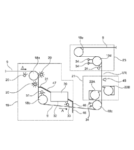
With reference to Fig. 4, the conditioning section 11 has a cleaning section
19 that
comprises at least one shower 20 arranged to act on the fabric 9 in the
conditioning part
11 of the fabric loop. The function of the shower or showers 20 is to wash
away
contaminants such as fibre residue from the fabric 9. In the embodiment shown
in Fig.
4, three showers 20 are shown as being arranged to act against the fabric 9
but it should
be understood that also embodiments with two showers 20 are possible and
embodiments with more than two showers 20, for example embodiments with three,
four, five or six showers 20 or even more than six showers 20. When more than
one
shower 20 is used, it is preferred that at least one shower 20 is arranged on
each side of
CA 03116305 2021-04-13
WO 2020/106193 PCT/SE2018/051198
8
the fabric 9. If only one shower 20 is used, this shower 20 should preferably
be arranged
to act against that side of the fabric 9 that has faced the fibrous web W and
come into
direct contact with the fibrous web W. At the end of the cleaning section, a
pair of seals
46 are arranged on opposite sides of the fabric 9 and opposite each other. In
this context,
it should be understood that the expression "opposite each other" does not
necessarily
mean that the seals 46 are placed exactly opposite each other since such a
positioning
could entail a risk that the seals 46 would pinch the fabric. To avoid the
risk of
pinching, the seals 46 may instead be placed such that there is a small offset
in the
machine direction between them. The seals 46 define the end of the cleaning
section. In
practice, the seals 46 may be, for example, a pair of foils made of a ceramic,
plastic or
metallic material. Conceivably, the seals 46 could also be rubber wipers. A
blade or foil
31 (for example a ceramic, plastic or metallic blade) may optionally be
arranged to wipe
off water from the fabric and guide water into a pan 30 over a guide 47. This
blade 31 is
placed in a position upstream (upstream in the direction of movement of the
fabric 9) of
the seals 46 that define the end of the cleaning section 19. The blade 31 has
the effect
that less water will pass into the nip between the fabric and the lower
turning roll 18
(see Fig. 4). This blade can also act to prevent contaminants freed by
previous showers
from being pressed back into the fabric 9 at the ingoing nip formed between
the fabric 9
and the rotating roll 18b._ A guide surface formed by an element 47 such as a
piece of
sheet metal forms a guide path for water such that water wiped off from the
fabric 9 by
the blade 31 can flow into a pan 30 that may suitably be arranged in the
cleaning
section.
After cleaning, the fabric 9 will have a substantial amount of water in it and
dewatering
is required to reduce energy consumption and to create optimum conditions for
the
application of a release agent and to aid with web transfer. Therefore, the
conditioning
section 11 also comprises a dewatering section 21 that is arranged to act on
the fabric 9
in the conditioning part 11 of the fabric loop in order to dewater the fabric
9 in an area
that lies after the cleaning section 19 in the predetermined direction of
movement of the
fabric 9. The dewatering section 21 comprises one or several suction
dewatering devices
22, 22A, 22B. The suction dewatering device(s) 22 dewater the fabric by means
of
suction. In the embodiment of Fig. 4, the dewatering section 21 has two
suction
dewatering devices 22A and 22B, one on each side of the fabric 9 but it should
be
understood that more than one suction dewatering device 22A, 22B may be used.
In Fig.
4, the suction dewatering device 22A is placed on the web-contacting side of
the fabric
9 and the suction dewatering device 22B is placed on the side of the fabric 9
that does
not contact the web W (when only the reference numeral 22 is used, it refers
to any
CA 03116305 2021-04-13
WO 2020/106193 PCT/SE2018/051198
9
suction dewatering device in the dewatering section). For example, there could
be three,
four, five or six such suction dewatering devices 22. Embodiments having only
one
such suction dewatering device 22 are also possible. When more than one
suction
dewatering device 22 is used, there should preferably be at least one suction
dewatering
device 22 on each side of the fabric 9.
In an area that lies after the dewatering section 21 in the predetermined
direction of
movement of the fabric 9, an applicator section 23 is arranged in the
conditioning part
11 of the fabric loop. The applicator section 23 comprises at least one
applicator 24 that
is arranged to apply a release agent on the fabric 9 for facilitating release
of a fibrous
web W from the fabric 9 at a later stage after the fibrous web W has been
dried on the
through air drying cylinder(s) 3, 5, in particular to facilitate release of
the fibrous web
W from the fabric 9 at the transfer point 15. The release agent may be, for
example, a
vegetable oil, a mineral oil or comprise vegetable and/or mineral oil.
According to the invention, the dewatering part of the fabric loop 9 comprises
a
substantially vertical run VR of the fabric 9 (see Fig. 4) and at least one
suction
dewatering device 22A is placed along the vertical run VR of the fabric 9 and
located on
the web-contacting side of the fabric 9 such that it can perform dewatering on
the web-
contacting side of the fabric 9. Furthermore, the dewatering section 21 is
designed such
that it either comprises a further suction dewatering device 22B that is
placed along the
vertical run VR of the fabric 9 on the side of the fabric 9 that is opposite
the web-
contacting side or that that the dewatering section 21 has room for installing
(along the
vertical run VR on the side opposite the web-contacting side of the fabric 9)
a further
suction dewatering device 22B of at least the same size as the suction
dewatering device
22A that is located on the web-contacting side of the fabric 9. The
predetermined
direction of movement of the fabric 9 in the vertical run VR of the fabric
loop along
which the at least one suction dewatering device 22A is placed is an upward
direction.
By placing the at least one suction dewatering device 22A along a vertical run
VR, the
advantage is attained that any water that leaves the fabric 9 as water mist or
droplets but
which is not sucked into any of the suction dewatering devices 22 will tend to
fall
downwards instead of instead of going in the direction in which the fabric 9
is moving.
In the context of this patent application, the term "substantially vertical"
should be
understood as meaning that the fabric run VR does not deviate more than 300
from a
perfectly vertical plane, preferably not more than 20 from a perfectly
vertical plane and
even more preferred not more than 10 . Ideally, the vertical run VR should be
perfectly
vertical and thus form an angle of 90 to the horizontal plane. However,
already
CA 03116305 2021-04-13
WO 2020/106193
PCT/SE2018/051198
inevitable imperfections in the manufacturing process and during the process
of
assembly may result in small deviations of one to four degrees. Already for
this reason,
the expression "substantially vertical" must be understood as including some
angles
having a small deviation from a perfectly vertical plane. Moreover,
limitations on
5 available space can sometimes make it necessary to deviate even more from
a perfectly
vertical plane. Deviations up to 100 are deemed by the inventors to have only
a small
detrimental effect while deviations larger than 30 are deemed totally
unacceptable.
When the suction dewatering box 22A is placed such that it can act on the web-
contacting side of the fabric 9, this entails the advantage that the advantage
that
10 rewetting of the fibrous web can be minimized when the fabric 9 contacts
the fibrous
web again. Since rewetting will be affected more by water remaining on the web-
contacting side of the fabric 9, it is especially important that dewatering is
achieved on
that side of the fabric 9.
If two suction dewatering devices 22 are placed along the vertical run VR on
opposite
sides of the fabric 9, the advantage is attained that dewatering can be
achieved with the
same efficiency on both sides of the fabric 9.
If only one suction dewatering box 22A is used in the dewatering section but
the
dewatering section has room for at least one additional suction dewatering box
22B on
the opposite side of the fabric 9, this entails the advantage that flexibility
is achieved. If
it is later found that more dewatering is required, an additional suction
dewatering box
22B can be added. Alternatively, other equipment can be added such as one or
several
sensors and/or one or several air knives.
An air knife 45 may advantageously be arranged to act against the fabric. The
air knife
(if one is used) can be placed in the dewatering section, for example after
the last
suction dewatering device 22, i.e. downstream of that suction dewatering
device 22 in
the predetermined direction of movement of the fabric 9. In the embodiment
shown in
Fig. 4, the air knife 45 is placed on the side of the fabric 9 that is
opposite the web-
contacting side of the fabric. As shown in Fig. 5, an air knife 45 may also be
placed on
that side of the fabric 9 that meets the fibrous web in the web-carrying part
of the fabric
loop.
One feature which may optionally be included in some embodiments of the
invention
will now be explained with reference to Fig. 5. In Fig. 5, some of the
components of
Fig. 4 are not shown since Fig.5 serves to explain a separate feature of the
invention.
The inventors of the present invention have found that, if the cleaning and
dewatering
sections are not sufficiently separated from each other, this may sometimes
have the
CA 03116305 2021-04-13
WO 2020/106193 PCT/SE2018/051198
11
consequence that water from the showers tends to carry along the fabric and
bypass the
dewatering equipment. This is undesirable since rewetting will occur with
adverse
effects to the subsequent transfer, molding and drying processes. While this
deficiency
may be less serious for slow speed machines, it can potentially become more
serious for
modern high-speed TAD machines that can operate at speeds of 1200 m/min or
higher.
Today (2018), new TAD machines are normally designed for speeds of about 1600
m/min but there is a general trend toward higher speeds and speeds of up to
2000 m/min
for TAD machines or even higher are conceivable and manufacturers of TAD
machines
need to consider what this may mean for the requirements of different machine
sections.
If the distance that separates the cleaning section from the dewatering
section is
increased, there will be more time for water to fall off from the fabric 9
such that the
fabric 9 will carry less water when it reaches the first suction dewatering
device 22 in
the dewatering section. The inventors have found that the risk of water being
carried
along and bypassing the dewatering equipment can be reduced if the shortest
distance in
the predetermined direction of movement of the fabric 9 between the end of the
cleaning
section 19 at the pair of seals 46 and a suction dewatering device 22 in the
dewatering
section 21 is selected to allow more water to fall off. With reference to Fig.
5, the
reference KA is used for the distance along the run of the fabric that extends
from the
point Sito the point S2., i.e. the shortest distance along the run of the
fabric 9 between
the end of the cleaning section 19 and a suction dewatering device 22 in the
dewatering
section. This can also be expressed in terms of the distance KA being the
distance from
the end of the cleaning section at the pair of seals 46 that define the end of
the cleaning
section 19 to the first suction dewatering device 22 in the dewatering
section. The
inventors have found that it is advantageous to select this distance such that
it lies in the
range of 2.5 m ¨ 6 m, (i.e. the distance KA from the pair of seals 46 to the
first suction
dewatering device 22 lies in that range). The distance 2.5 m is regarded as a
lower limit
for machine speeds of 1500 m/min while a larger distance may be desirable at
higher
speeds. At a machine speed of 2000 m/min, the shortest distance KA may be
selected to
be 3.5 m and could well be 5 m. For most practical applications with current
machine
speeds, it is deemed that a shortest distance KA may be in the range of 3 m ¨
5 m. For
machine speeds exceeding 2000 m/min, for example up to 2200 m/min, it may be
suitable to use a shortest distance KA which is up to 6 m. However, due to the
limitations imposed by available space, a distance exceeding 6 m is deemed
impractical
in most realistic cases. By selecting the shortest distance KA in the range of
2.5 m ¨ 6
m, the amount of water that is carried along by the fabric 9 to the dewatering
equipment
can be reduced such that the risk of disturbances to the subsequent transfer,
molding and
drying processes are correspondingly reduced. While such a selection of the
shortest
CA 03116305 2021-04-13
WO 2020/106193 PCT/SE2018/051198
12
distance KA can thus be advantageous, it should be understood that this
selection is an
optional feature and that embodiments of the invention are possible in which
the
shortest distance KA lies outside the range of 2.5 m ¨ 6 m. Embodiments of the
invention are thus conceivable in which the distance KA is significantly
smaller than
2.5 m. For example, the shortest distance KA may be only 1 m or even less than
1 m.
Likewise, embodiments are conceivable in which the shortest distance KA is
larger than
6 m. For example, it could be as large as 8 m or even more than 8 m. As
previously
mentioned, there may be a small offset between the seals 46. For clarity, it
may be
mentioned that for cases where there is an offset between the seals 46, the
point Si is
defined by that seal 46 which, in the direction of movement of the fabric 9,
is closest to
the first suction dewatering device 22 in the dewatering section.
Reference will now be made to Fig. 4 and to Fig. 6. In embodiments in which at
least a
part of the dewatering section 21 is located in a vertical run VR in which the
predetermined direction of movement of the fabric 9 is an upward direction, it
is
preferable that the fabric 9 wraps a lead roll 18c at the beginning of the
part of the fabric
loop where the fabric 9 extends vertically. That roll 18c will then serve as a
lower
turning roll around which the fabric 9 changes its direction of movement to an
upward
direction (see Fig. 4 and Fig. 6). Preferably, two doctors 34 are arranged to
act on that
lead roll 18c to remove contaminants such as fibre residue from the lead roll
18. With
continued reference to Fig. 6, contaminants tend to get stuck on the surface
of the lead
roll 18c and may form lumps 50 as indicated in Fig. 6. Contaminants (e.g.
fibres) within
the structure of the fabric 9 is detrimental to drying uniformity (In the
machine direction
MD and in the cross-machine direction CD) as well as overall TAD energy use.
For the
TAD (through air drying) fabric to function properly, it must have a high and
uniform
air permeability, hence the requirement for thorough cleaning of the web.
Larger pieces
of contaminants ¨ lumps ¨ embedded or pressed into the TAD fabric will impede
drying
in this localized area and create a weak spot. Even with a properly
functioning system of
showers 20 and suction dewatering devices 22, there are still contaminants
such as
residual fibre on and within the TAD fabric 9. These contaminants will
transfer to any
sheet side and non-sheet side and rolls that the fabric 9 contacts after
having left the
cleaning section. These contaminants must be removed from the rolls, otherwise
the
contaminants will build up to create larger lumps and be pressed or "ironed"
back into
the TAD fabric. The inventors have found from practical experience that, if
the
contaminants are pressed back into the TAD fabric, this will create a
"contaminated"
spot on the fabric 9 (the TAD fabric) which can interfere with sheet transfer.
Furthermore, this area is much less permeable to air and air permeability of
the fabric 9
CA 03116305 2021-04-13
WO 2020/106193 PCT/SE2018/051198
13
is required at the suction device 13 and the molding box 52. Air permeability
is also
required when the fabric 9 passes over through air drying cylinders 3, 5.
Those parts of
the fibrous web W that come into contact with contaminated spots of the fabric
9 will
not dry properly compared to the rest of the fibrous web thus creating wet
spots that
may create holes or other defects in the ready-dried paper product.
The inventors have found that the technical problem of contaminants on the
lower
turning roll can be counteracted by the use of double doctor blades on the
sheet side and
possibly non-sheet side rolls after the cleaning section. Possibly, double
doctors can
also be used on non-sheet side rolls. The double doctor blades will ensure the
roll 18c is
doctored twice every revolution so that any contaminants that might get past
the doctor
blade of the first doctor 34 will be captured and doctored by the second
doctor blade.
Therefore, the roll coming back to meet the fabric 9 will be contaminate free
which will
minimize if not eliminate the possibility of any contaminants (for example
fibre or fibre
lumps) from being pressed or "ironed" back into the air permeable fabric 9
creating a
wet spot and hole in the paper. Therefore, in order to remove contaminants
such as fibre
residue from the roll 18 that serves as a lower turning roll before the
suction dewatering
device(s) in the dewatering section 21, the inventors have found that two
doctor blades
34 should be arranged to act against that roll to scrape off contaminants from
the surface
of the roll. The inventors have found that just one doctor blade 34 is
insufficient and
that contaminants may pass such a single doctor blade 34 and be pressed into
the fabric
9.
To minimize the risk of roll wear from the application of double doctoring and
to assist
in removing contaminants (for example fibre residue), it might be necessary to
apply a
low pressure, low volume misting shower between the doctor blades to gently
lubricate
the roll and contaminants. As can be seen in Fig. 6, a misting shower 48 may
advantageously (but not necessarily) be arranged between the two doctors 34 to
minimize roll wear and assist in removing fibre and other contaminants.
The same arrangement with two doctors 34 can be used also on the lead roll 18d
at the
end of that part VR of the fabric loop where the fabric 9 extends vertically
and those
two doctors can act against the lead roll 18d to remove contaminants from the
lead roll
18d and a misting shower 48 may advantageously (but not necessarily) be placed
between those doctors 34.
Preferably, at least a part of the cleaning section 19 is arranged in a part
of the fabric
loop in which the predetermined direction of the fabric 9 is a downward
direction. This
entails the advantage that that it becomes easier to arrange at least a part
of the
CA 03116305 2021-04-13
WO 2020/106193 PCT/SE2018/051198
14
dewatering section 21 in an upward run without unduly increasing the overall
height of
the entire conditioning part 11.
Another feature of the inventive drying section which may advantageously be
included
in such embodiments of the invention that use a Yankee drying cylinder 16 with
a
smooth outer surface 27 will now be explained with reference to Fig. 7, Fig. 8
and Fig.
9. The inventors have found that the rotation of the Yankee drying cylinder 16
(indicated by arrow R) and the movement of the fabric 9 (indicated by arrow A)
will
cooperate to generate a stream of air in the direction of arrow L, i.e. upward
and against
the machine direction MD, see Fig. 7. Moreover, the inventors have found that
this
stream of air is likely to carry fibre particles that may subsequently fall
down on the
forming and drying sections. In preferred embodiments of the invention, the
conditioning part 11 of the loop of the air permeable fabric 9 is located
vertically above
the web-carrying part 10. Fibre particles entrained by the air stream L which
is
generated by the movement of the Yankee drying cylinder 16 and the fabric 9
will then
fall predominantly on the conditioning part 11. If fibre particles should fall
on the
conditioning part 11, this will counteract the cleaning which is performed and
is thus
highly undesirable. With reference to Fig. 8 and to Fig. 9, a suction and
blowing device
29 may be placed above a part of the conditioning part 11 of the fabric loop
located
adjacent the Yankee drying cylinder, i.e. in the area which will be reached by
the air
stream L generated by the fabric 9 and the Yankee drying cylinder 16. The
suction and
blowing device 29 is arranged suck in air and blow the air away from the area
above the
conditioning part 11 of the fabric loop. Preferably, the air is blown away
from the
suction/blowing device 29 in a direction indicated by arrow B in Fig. 9, i.e.
in the Cross
Direction (CD) which is horizontal and perpendicular to the machine direction
MD.
Here, it should be understood that the machine direction MD is defined as the
direction
in which the drying section 2 is arranged to carry the fibrous web W through
itself. The
idea of using a suction/blowing device 29 cooperates with the other features
of the
inventive drying section to improve conditioning of the fabric 9 but may also
be used
independently of how the conditioning part of the fabric loop is otherwise
designed.
Optionally, a hood 28 may be placed over at least a part of the conditioning
part 11 of
the fabric loop to prevent fibre residue to fall on the conditioning part 11,
preferably the
hood 28 should cover a part of the fabric 9 that lies in the area above that
TAD cylinder
that is closest to the Yankee drying cylinder 16. Instead of falling directly
on the
conditioning part 11, fibre residue will land on top of the hood 28, i.e. on
the roof of the
hood 28. In embodiments of the invention, the entire conditioning part 11 may
be
CA 03116305 2021-04-13
WO 2020/106193 PCT/SE2018/051198
covered by such a hood 28. If both a suction/blowing device 29 and a hood 28
are used,
the suction/blowing device 29 may be integrated with the hood 28.
With reference to Fig. 4 and Fig. 5, the cleaning section includes a vertical
or
substantially vertical run between an upper lead roll 18a and a lower lead
roll 18b which
5 upper and lower lead rolls 18a, 18b serve as turning rolls where the
fabric 9 changes its
course. A shower 51 may be arranged to act on the lower lead roll 18b (turning
roll 18b)
in the cleaning section to wash away fibre residue from that roll. Prior to
the
dewatering section 21, the fabric changes its direction of movement around a
lower lead
roll 18c (turning roll 18c) after which the fabric 9 runs along the upward
vertical run
10 YR. Between the lower lead rolls 18a, 18c, the fabric 9 follows a run
which is
horizontal or deviates from the horizontal plane by preferably not more than
15 and
even more preferred by not more than 50 and the last part of the cleaning
section with
the seals 46 is located on that substantially horizontal run between the lower
lead rolls.
In preferred embodiments, a pan 30 may be arranged above the substantially
horizontal
15 fabric run that extends between the lower lead rolls 18b, 18c and a
blade 31 which is
arranged in the vertical run between the upper and lower lead rolls 18a, 18b
is arranged
to act against the fabric 9 to wipe off water from the fabric 9 and guide
water that has
been wiped from the fabric 9 into the pan 30. In preferred embodiments, the
pan 30 has
a bottom wall 32 that faces the fabric 9 and at least one shower 33 is
arranged to wash
away fibre residue from the bottom wall 32. Embodiments are conceivable in
which
only one such shower 33 is used but embodiments using two, three or more than
three
showers are also conceivable. The at least one shower 33 that is arranged to
act against
the bottom wall 32 prevents or reduces the risk that fibre particles build up
to form great
lumps on the bottom wall 32. If great lumps of fibre build up on the bottom
wall 32,
such lumps will eventually fall onto the fabric 9 where they may cause
problems, for
example at the next lead roll 18c. While the upper seal 46 at the end of the
cleaning
section may wipe off such lumps, that could lead to a build-up of lumps at the
seal 46
which would also be undesirable. When the shower 33 acts on the bottom wall
32, the
fibres can be washed off continuously or intermittently before they have
formed lumps.
Preferably, the fibres are washed off intermittently from the bottom wall 32
by the
shower 33. It should be understood that more than one shower 33 may be
arranged to
act against the bottom wall 32. For example, there may be two showers 33,
three
showers 33 or more than three showers 33. Each part of the fabric 9 will
receive only a
small amount of fibre residue from the bottom wall 32 and such fibre residue
can be
more easily dealt with at following stations.
CA 03116305 2021-04-13
WO 2020/106193 PCT/SE2018/051198
16
In the embodiments described with reference to Fig. 1 ¨ Fig. 8, the fibrous
web W is
picked up by the fabric 9 from a fabric 39 that belongs to a preceding machine
section
14 such as the forming section and the fabric 39 may be one of the forming
fabrics or it
may be a fabric that as received the fibrous web from one of the forming
fabrics. An
alternative embodiment in which the inventive drying section may also be used
will
now be described with reference to Fig. 10. In the embodiment of Fig. 10, the
fabric 9
does not receive the fibrous web W from one of the forming fabrics (as shown
in Fig.
1). Instead, the fabric 9 is itself used as a forming fabric and wraps the
forming roll 37.
In this embodiment, the receiving point 12 is the point where the fabric 9
meets the
forming fabric 38 to cooperate with the forming fabric 38 to form an embryonic
web W.
Due to the different configuration of the paper making machine 1, the
direction of
rotation R of the through air drying cylinders 3, 5 is counter-clockwise, i.e.
opposite the
direction of rotation R that is shown in the embodiment of Fig. 1. With regard
to the
arrangement and operation of the conditioning part 11 of the loop of the
fabric 9, the
embodiment of Fig. 10 functions in the same way as the embodiment described
with
reference to Fig. 1 ¨ Fig. 8 and Fig. 9. In this context, it should be
understood that the
TAD section with the through air drying cylinders 3, 5 may have many different
configurations and the configurations shown in Fig. 1 and Fig 10 are only
examples of
possible configurations. For example, the TAD section could be designed such
that it
comprises only one through air drying cylinder which may optionally be
combined with
a Yankee drying cylinder that follows the through air drying cylinder. Each
through air
drying cylinder and its associated hood 7, 8 may be designed for blowing air
from the
hood and into the through air drying cylinder or for blowing air from the
inside of the
through air drying cylinder into the associated hood 7,8.
The inventive way of conditioning the fabric 9 may conceivably also be used in
other
kinds of paper making machines than machines using through air drying
cylinders. For
example, the inventive way of conditioning the fabric may be used for a
machine in
which a structured fabric 9 as described previously is used in a press nip in
which a
three-dimensional pattern is created in a fibrous web when a patterned side of
the fabric
contacts the fibrous web in a press nip whereafter the fibrous web is carried
by the
structured/textured fabric 9 to a Yankee drying cylinder where the fibrous web
is
transferred from the structured/textured fabric 9 to the surface of the Yankee
drying
cylinder. After the structured/textured fabric has delivered the fibrous web
to the
Yankee drying cylinder, the structured/textured fabric may need conditioning
which
may be carried out in a conditioning section as described in this patent
application.