Note: Descriptions are shown in the official language in which they were submitted.
CA 03116439 2021-04-14
PCT/EP2019/074699 / 2018P23158W0
1
Description
Pneumatic brake for a rail vehicle
Technical field
The invention relates to a pneumatic brake for a rail vehicle.
Prior art
Rail vehicles are overwhelmingly fitted with pneumatic brakes.
Two significant forms of embodiment can be distinguished here.
In a first embodiment, which is mainly used for standard
railroads, the pneumatic pressure acts in a cylinder and
presses a friction lining onto an opposite surface. The
compressed air is in this case supplied via a compressed air
line extending throughout the train, by means of which
auxiliary air reservoirs arranged in the cars are filled. The
application of the brakes is initiated by reducing the
pressure in the compressed air line, wherein a control valve
uses the pressure stored in the auxiliary air reservoirs to
press on the friction linings. The advantage of this
embodiment is that if the pressure supply fails or a leak
occurs, braking is performed automatically. In the case of
other trains, for example subway trains, brakes are also used
in which the pneumatic pressure for pressing the brake linings
is regulated by an electrically actuated brake valve. In this
form of embodiment a defect in the pneumatic system is more
critical, and in addition a series of further systems is
frequently supplied from the same compressed air system (door
drives, coupling actuation, flange lubrication, etc.) so that
the number of potentially faulty components and thus the
probability of failure of the entire compressed air system is
Date Recue/Date Received 2021-04-14
CA 03116439 2021-04-14
PCT/EP2019/074699 / 2018P23158W0
2
increased. This can be countered by increasing redundancy,
wherein for example multiple air compressors are provided,
distributed over the train. Even if a component fails, for
example all brakes of a chassis, the braking rate values
required for approval must still be guaranteed. To this end,
what are known as brake air reservoirs can be used, which
store the compressed air needed for the immediate braking
operations and thus form a buffer between the brake system and
the general compressed air supply. This means that even if the
general compressed air supply fails, some braking operations
can still be performed, since the actual brake system is
connected to the general compressed air supply via a non-
return valve which prevents a return flow from the brake
system if the air pressure in the general compressed air
system drops. A brake air reservoir can be provided for each
chassis, so that any failure of a brake air reservoir affects
the brakes of one chassis. However, if only one brake air
reservoir is provided per vehicle, all the brakes of a vehicle
would be out of operation in the event of a failure (leak,
destruction, falling off the vehicle, etc.) of the brake air
reservoir. Likewise, a failure of a brake air reservoir means
that the rest of the compressed air system, e.g. the door
drives, are likewise no longer operable. Since the space
available on the chassis or beneath the underframe is
restricted, it is desirable for just one brake air reservoir
to have to be provided per car, though failure of this however
means the loss of all the brakes of a car.
Presentation of the invention
The object of the invention is hence to specify a pneumatic
brake for a rail vehicle which remains operable even if a
brake air reservoir fails.
Date Recue/Date Received 2021-04-14
CA 03116439 2021-04-14
PCT/EP2019/074699 / 2018P23158W0
3
The object is achieved by a pneumatic brake for a rail vehicle
having the features of claim 1 and a rail vehicle according to
claim 5. Advantageous embodiments are the subject matter of
subsidiary claims.
According to the basic idea of the invention, a pneumatic
brake for a rail vehicle is described, in which during a
braking operation friction linings are pressed onto friction
partners by means of pneumatic pressure from a brake air
reservoir and wherein the brake air reservoir is fed from a
compressed air supply and wherein the filling and outflow of
compressed air from the brake air reservoir takes place via a
flow limiting device.
As a result, the advantage can be achieved that even in the
event of a loss of pressure maintenance in the brake air
reservoir the operational capability of the brakes is still
retained, at least with reduced braking capacity. The reason
why the pressure maintenance in the brake air reservoir has
been reduced or has failed is irrelevant here. If there is a
compressed air supply in the vehicle, braking operations can
continue to be carried out even if the brake air reservoir
fails.
According to the invention, a flow limiting device is arranged
in the supply line to the brake air reservoir, via which each
inflow and outflow of compressed air takes place.
If there is a failure in pressure maintenance in the brake air
reservoir, the flow limiting device reduces the volume flow of
the compressed air flowing out of the brake system to a level
which can be subsequently delivered from the compressed air
supply without an excessive pressure drop thereby taking
Date Recue/Date Received 2021-04-14
CA 03116439 2021-04-14
PCT/EP2019/074699 / 2018P23158W0
4
place.
During the filling of the brake air reservoir the use of said
flow limiting device is irrelevant, since although the filling
therefore takes place more slowly, this does not represent a
disadvantage due to the substantially shorter brake setup time
when compared to the fill times. The air reservoir is filled
from the compressed air supply both during the journey and
while the vehicle is stationary, and compressed air is removed
from the brake air reservoir only directly during the
pressurization in the brake cylinders. In vehicles fitted with
wheel slip protection, a repeated discharge of compressed air
and subsequent refilling of the brake cylinders takes place
during braking with an engagement of the wheel slip protection
system, as a result of which the consumption of compressed air
is increased. Even in this operating state, a brake according
to the invention can make available the compressed air needed
for braking.
A first advantageous embodiment of the invention provides for
the flow limiting device to be formed from a parallel
connection of a non-return valve with a restrictor. In this
case the forward direction of the non-return valve is oriented
from the brake air reservoir to the brake system. In this way
compressed air can flow rapidly out of the brake air reservoir
to the brake cylinders during the braking operation, such that
even when the invention is used no disadvantageous braking
behavior occurs, since the braking pressure can be built up
just as rapidly as without the flow limiting device. In the
event of a loss of pressure maintenance in the brake air
reservoir, compressed air flows out of the compressed air
supply into the environment via the nozzle, rather than via
the non-return valve which in this case is self-closing. The
Date Recue/Date Received 2021-04-14
CA 03116439 2021-04-14
PCT/EP2019/074699 / 2018P23158W0
pressure drop in the pneumatic system occurring due to the
outflow of the compressed air via the nozzle is determined by
the open cross-section of the nozzle. The nozzle should be
dimensioned such that in the event of a failure an
impermissibly low pressure does not occur in the brake system
which reduces the braking behavior, i.e. the potential braking
rate. In this case the nozzle can be provided with a fixed
cross-section, or a variable, adjustable nozzle can be
employed.
A preferred embodiment of the invention provides that the non-
return valve and the nozzle can embodied as a unit with one
common housing. Thanks to this embodiment as a restrictor non-
return valve the complexity of the pneumatic tubing of the
brake system can be reduced.
A further preferred embodiment of the invention provides that
the flow limiting device is embodied in the form of an
overflow valve. An overflow valve such as this means that the
compressed air does not flow until a particular absolute
pressure is reached and in one form of embodiment it comprises
a non-return valve for the direction of drainage out of the
brake air reservoir toward the brakes. Using an overflow valve
means that even in the event of a failure, no pressure loss
occurs in the brake system.
Brief description of the drawings
These show by way of example:
Fig.1 Brake system with a flow limiting device.
Fig.2 Brake system with a flow limiting device in the form of
an overflow valve.
Date Recue/Date Received 2021-04-14
CA 03116439 2021-04-14
PCT/EP2019/074699 / 2018P23158W0
6
Explanation of the invention
Fig.1 shows by way of example and schematically a brake system
with a flow limiting device. The pneumatic circuit diagram of
part of a compressed air system of a rail vehicle with a
pneumatic brake 1 is illustrated. A compressed air supply 3 is
fitted with a main air reservoir 11, which serves to supply
compressed air, such that even when the requirement for
compressed air is briefly high, the pressure in the pneumatic
system does not drop sharply. The compressed air system
comprises a plurality of further components such as
compressors, pressure regulators, measuring devices and
consumer loads such as door drives, folding step drives, etc.
To simplify the illustration these are not shown in Fig.l. The
pneumatic brake system 1 is supplied with compressed air from
the general compressed air system, wherein a brake non-return
valve 4 prevents the return flow of compressed air from the
pneumatic brake system 1 into the general compressed air
system. Thus the pressure in the pneumatic brake system 1 is
maintained even if the general compressed air system is out of
operation, e.g. because of a defect in one of its components,
and the pressure in it drops or disappears completely. The
pneumatic brake system 1 comprises a brake valve 5 which can
be actuated by the train crew or the vehicle control system
and which in this case conducts a pneumatic pressure
proportional to the desired braking rate to the brake
actuators 6. The brake actuators 6 each comprise a pneumatic
cylinder, the force action of which is used to press brake
linings onto brake disks. In the exemplary embodiment shown,
two brake actuators 6 are represented in the embodiment as
disk brakes. However, the number and embodiment of the brake
actuators 6 is unimportant. The pneumatic brake 1 is
Date Recue/Date Received 2021-04-14
CA 03116439 2021-04-14
PCT/EP2019/074699 / 2018P23158W0
7
furthermore fitted with a brake air reservoir 2 which has a
supply of air available exclusively for braking operations and
which is also filled from the compressed air supply 3 via the
brake non-return valve 4. In conventional brake systems, in
the event of a defect (loss of pressure maintenance) in this
brake air reservoir 2 the pneumatic pressure in the pneumatic
brake 1 would, as a function of the cross-section of the
opening through which compressed air escapes and the volume
flow continuing to flow out of the compressed air supply 3,
drop so sharply that in some cases no further braking would be
possible. According to the invention, a restrictor non-return
valve 7 is therefore arranged in the supply line to the brake
air reservoir 2, and comprises a parallel connection of a
restrictor 8 and a non-return valve 9. In the event of a loss
of pressure maintenance of the brake air reservoir 2 the
pneumatic brake 1 thus vents into the open air via the
restrictor 8, wherein because of the outflow opening
restricted by the nozzle 8 the pressure drop in the pneumatic
brake 1 is sharply reduced and in any case still permits
braking so long as the compressed air supply 3 is in
operation. The non-return valve 9 connected in parallel to the
nozzle 8 permits a rapid removal of compressed air,
uninfluenced by the nozzle 8, from the brake air reservoir 2
in normal operation. The brake air reservoir 2 is filled from
the compressed air supply 3 at a somewhat reduced rate because
of the nozzle 8. In concrete forms of embodiment, pressure
measurement devices are also provided at the pneumatic brake
1, by means of which a pressure drop can be identified; these
are not illustrated in Fig.l.
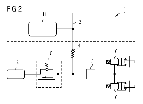
Fig.2 shows by way of example and schematically a brake system
with a flow limiting device in the form of an overflow valve.
The pneumatic circuit diagram of part of a compressed air
Date Recue/Date Received 2021-04-14
CA 03116439 2021-04-14
PCT/EP2019/074699 / 2018P23158W0
8
system of a rail vehicle with a pneumatic brake 1 as in Fig. 1
is illustrated. Except for the flow limiting device all the
components are identical. In the exemplary embodiment shown
this flow limiting device is constructed in the form of an
overflow valve 10 which in the event of a loss of pressure
maintenance of the brake air reservoir 2 prevents an
unrestricted outflow of compressed air, thus ensuring that the
air pressure in the pneumatic brake 1 remains sufficient for
braking operations.
Date Recue/Date Received 2021-04-14
CA 03116439 2021-04-14
PCT/EP2019/074699 / 2018P23158W0
9
List of reference characters
1 Pneumatic brake
2 Brake air reservoir
3 Compressed air supply
4 Brake non-return valve
Brake valve
6 Brake actuator
7 Restrictor non-return valve
8 Restrictor
9 Non-return valve
Overflow valve
11 Main air reservoir
Date Recue/Date Received 2021-04-14