Note: Descriptions are shown in the official language in which they were submitted.
CA 03116454 2021-04-14
WO 2020/079105 -1- PCT/EP2019/078128
Optical lens
FIELD OF THE INVENTION
The disclosure relates to a method implemented by computer means for
determining a lens element. The disclosure also relates to methods implemented
by
computer means for determining transfer laws associated with a coating process
of a
lens element.
Additionally, the disclosure relates to a lens element intended to be worn in
front of an eye of a person to slow down and/or prevent a progression of
abnormal
refractions of the eye such as myopia or hyperopia.
Furthermore, the disclosure relates to a method implemented by computer
means for determining a mold for a lens element.
Additionally, the disclosure relates to a mold for a lens element a plurality
of
optical elements having a targeted optical function and intended to be covered
by at
least one layer of at least one coating element.
BACKGROUND OF THE INVENTION
Myopia of an eye is characterized by the fact that the eye focuses distant
objects in front of its retina, hypermetropia is characterized by the fact
that the eye
focuses distant objects behind of its retina. Myopia is usually corrected
using a
concave lens providing negative dioptric power and hypermetropia is usually
corrected using a convex lens providing positive dioptric power.
It has been observed that some individuals when corrected using conventional
single vision optical lenses, in particular children, focus inaccurately when
they
observe an object which is situated at a short distance away, that is to say,
in near
vision conditions. Because of this focusing defect on the part of a myopic
child
which is corrected for his far vision, the image of an object close by is also
formed
behind his retina, even in the foveal area.
Such focusing defect may have an impact on the progression of myopia of
such individuals. One may observe that for most of said individual the myopia
defect
tends to increase over time partly caused by long and intensive near work
sessions.
CA 03116454 2021-04-14
WO 2020/079105 -2- PCT/EP2019/078128
In particular, studies carried out on monkeys have shown that strong
defocusing of the light behind the retina, which occurs away from the foveal
zone,
may cause the eye to extend and therefore may cause a myopia defect to
increase.
Optical lenses usually undergo numerous treatments adding multiple
properties to the lenses. For example, the use of anti-scratch and anti-
reflective
treatments have become commonplace. Such treatments mostly correspond to an
application of a coating layer on a surface of the optical lens, adding
specific
properties to said covered surface.
However, the use of classic treating methods is rendered difficult for lenses
having complex designs, such as the recently developed optical lenses
comprising
optical elements placed on its surface to prevent, or at least slow down, the
progression of abnormal refractions of an eye such as myopia or hyperopia.
Indeed, the thickness of the coating layer usually used to treat the surfaces
of
a lens is not negligible when compared to the size of optical elements placed
on said
surface. For example, the index of refraction of the coating layer covering
optical
elements may impact the light ray transmission and thus modify the optical
function
of said optical elements. Even a slight thickness heterogeneity of the coating
layer
covering the optical elements may modify the optical function of said optical
elements.
Therefore there is a need to provide a method to determine a lens element
comprising optical elements to prevent or at least slow down the progression
of the
abnormal refraction of the eye that would compensate and correct the
modification of
the lens element properties induced by a treatment of said lens element.
Additionally, there is a need to provide a method to determine a mold for lens
element comprising optical elements to prevent or at least slow down the
progression
of abnormal refraction of the eye of the wearer that would compensate and
correct
the modification of the lens element properties induced by a treatment of said
lens
element.
SUMMARY OF THE INVENTION
CA 03116454 2021-04-14
WO 2020/079105 -3- PCT/EP2019/078128
To this end, the invention proposes a method for example, implemented by
computer means for determining a lens element, the lens element comprising:
- a holder comprising a refraction area having a first refractive power;
- a plurality of optical elements placed on at least one surface of the
holder, the
plurality of optical elements having a second refractive power that differs
from the
first refractive power of the holder; and
- at least one layer of at least one coating element covering at least a
zone of at
least one optical elements and at least a zone of the holder on which the
optical
elements are placed,
wherein the method comprises:
- providing lens data, the lens data indicating at least a shape of the
lens
element to be determined, the shape of the lens element corresponding to a
shape of
the holder and to at least a shape of the optical elements of the lens
element, the
shape of the optical elements being associated with a targeted optical
function;
- providing a coating lens transfer law associated with a coating process of a
lens element comprising the optical elements, the coating process being
associated
with the coating element, the coating lens transfer law corresponding to
transformations to apply to the shape of the surface of the lens element
comprising
the optical elements for compensating modifications of the targeted optical
function
of said optical elements induced by the coating process; and
- determining the lens element, for example adapted for the wearer, based
at
least on the lens data and the coating lens transfer law.
Advantageously, determining the lens element based on the lens data and the
coating lens transfer law allows tuning the design of the uncovered lens
element in
order to obtain an accurate treated lens element having a targeted optical
function,
for example adapted for a wearer once covered by the coating layer.
According to further embodiments which can be considered alone or in
combination:
- the
method further comprises manufacturing a lens element based on
the determined lens element, for example adapted for a wearer; and/or
CA 03116454 2021-04-14
WO 2020/079105 -4-
PCT/EP2019/078128
- the
method further comprises coating at least a zone of the surface and
at least a zone of the at least one optical element with at least one coating
element
based on the coating process.
The disclosure further relates to a method implemented by computer means
for determining a transfer law associated with a coating process of a lens
element, the
method comprising:
- providing a lens element, the lens element comprising:
o a
holder comprising a refraction area having a first refractive power,
o at least one optical element having at least one targeted optical
function and placed on at least one surface of the holder, the at least
one targeted optical function being different from the first refractive
power,
- coating at least a zone of the holder and at least a zone of at least one
optical
element with at least one coating element based on a coating process, the
coating
process being associated with the at least one coating element;
- measuring at least one optical characteristic of at least a zone of the
at least
one optical element covered by the coating element;
- determining at least one optical characteristic error based on a
comparison of
the measured at least one optical characteristic of the coated optical element
and the
at least one targeted optical function;
- compiling information corresponding to the determined optical
characteristic
error into database as correction information;
-
determining a transfer law associated with the coating process and the at
least
one optical element based on the correction information of the database, the
transfer
law correcting an original shape of the surface of the lens element comprising
the at
least one optical element so that once coated by the at least one coating
element, said
at least one coated optical element reaches a targeted optical function.
According to further embodiments which can be considered alone or in
combination:
CA 03116454 2021-04-14
WO 2020/079105 -5- PCT/EP2019/078128
the method comprises, prior to the measuring step, a step of
polymerizing the at least one coating element covering a zone of the holder
and at
least a zone of at least one optical element; and/or
the method comprises, further to the coating step, a second step of
coating at least a zone of the holder and at least a zone of at least one
optical element
with at least one coating element based on a coating process, the coating
process
being associated with the at least one coating element; and/or
the at least one coating element comprises anti-abrasion features;
and/or
the method comprises a step S30a of providing a mold for a lens
element a person and a step S30b of obtaining a lens element a person by
molding it;
and/or
the transfer law is a coating lens transfer law for correcting an original
shape of the surface of the lens element comprising the at least one optical
element
so that once coated by the at least one coating element, said at least one
coated
optical element reaches a targeted optical function and/or
the transfer law is a coating mold transfer law for correcting an
original shape of a surface of the mold for a lens element comprising at least
one
surfacic element corresponding to the at least one optical element so that
once
molded and coated by the at least one coating element, the at least one coated
optical
element of the molded and coated lens reaches a targeted optical function.
Another aspect of the disclosure relates to a lens element, for example
adapted for a person, and comprising:
- a holder comprising a refraction area having a refractive power based on a
prescription for correcting an abnormal refraction of the person;
- a plurality of optical elements placed on at least one surface of the holder
so
as to at least one of slow down, retard or prevent a progress of the abnormal
refraction of the eye of the person; and
- at least one layer of at least one coating element covering at least a zone
of at
least one optical element and at least a zone of the holder on which the
optical
elements are placed,
CA 03116454 2021-04-14
WO 2020/079105 -6- PCT/EP2019/078128
wherein said at least one layer of at least one coating element adds an
optical power
of 0.1 diopter in absolute value in specific wearing conditions when measured
over
said zone of the optical element covered by said at least one layer of at
least one
coating element.
Advantageously, having the at least one layer of at least one coating element
participating to the optical power of the optical element allows obtaining a
lens
element comprising coated optical elements with a specific targeted optical
function
as well as specific treatments. In other words, the at least one layer of at
least one
coating element participates to the optical function of the coated optical
element
while providing specific features associated with the coating process of a
treatment.
According to further embodiments which can be considered alone or in
combination:
the specific wearing condition corresponds to the standard wearing
condition; and/or
the abnormal refraction of the eye is myopia; and/or
the at least one layer of a coating element covering at least one optical
element is thicker at the periphery of a surface of said coated optical
elements; and/or
the at least one layer of coating element covering at least one optical
element is thicker at the center of a surface of said coated optical elements
than at the
edge of the surface of said coated optical elements; and/or
at least a part of the plurality of optical elements are placed on at least
a ring on the at least one surface of the holder; and/or
the plurality of optical elements are placed on concentric rings on the
at least one surface of the holder; and/or
the mean sphere of all the coated optical elements placed on a
concentric ring is identical; and/or
the mean sphere of at least part of the coated optical elements varies
from the center to the edge of the lens element; and/or
the mean sphere of at least part of the coated optical elements
decreases from the center to the edge of the lens element; and/or
CA 03116454 2021-04-14
WO 2020/079105 -7- PCT/EP2019/078128
the mean sphere of at least part of the coated optical elements
increases from the center to the edge of the lens element; and/or
at least part of the optical elements are contiguous.
Another aspect of the disclosure relates to a method implemented by
computer means for determining a mold for a lens element and comprising
- a holder comprising a refraction area having a refractive power;
- a plurality of optical elements placed on at least one surface of the
holder and having a targeted refractive power different from the first
refractive
power of the holder; and
wherein at least a zone of at least one optical elements and at least a zone
of
the holder on which the optical elements are placed are intended to be covered
by at
least one layer of at least one coating element,
wherein the method comprises:
- providing mold
data indicating at least an initial shape of the mold, the
initial shape of the mold corresponding to a shape of the surface of the
holder and to
at least a shape of the optical elements of the lens element, the shape of the
optical
elements being associated with the targeted optical function;
- providing a coating mold transfer law associated with a coating
process of a lens element comprising the optical elements, the coating process
being
associated with the coating element, the coating mold transfer law
corresponding to
transformations to apply to the shape of the mold for compensating
modifications of
the targeted optical function of said optical elements induced by the coating
process;
and
- determining a
shape of the mold for a lens element based at least on
the mold data and the coating mold transfer law.
Advantageously, determining a mold for a lens element based on the mold
data and the coating mold transfer law allows tuning the design of the mold to
easily
produce a large number of uncovered lens element in order to obtain an
accurate
treated lens element, for example adapted for a wearer once covered by the
coating
layer.
CA 03116454 2021-04-14
WO 2020/079105 -8- PCT/EP2019/078128
According to further embodiments which can be considered alone or in
combination:
- the method further comprises providing a cooling transfer law
associated with a cooling process of a molded lens element comprising optical
elements, the cooling transfer law corresponding to transformations to apply
to the
shape of the mold for compensating modifications of the targeted optical
function of
said optical elements induced by the retraction of the lens element material
during
the cooling process, wherein the shape of the mold for a lens element is
determined
based on the mold data, the coating mold transfer law and the cooling transfer
law.
The disclosure further relates to a mold for a lens element comprising a
plurality of optical elements having a targeted optical function and intended
to be
covered by at least one layer of at least one coating element, comprising:
- a first molding element having a first surface, the first surface having
a first surfacic curvature and comprising a plurality of surfacic elements
having at
least a second surfacic curvature that differs from the first,
- a second molding element having a second surface,
- a gasket having an inner and an outer surfaces,
wherein the first surface of the first molding element, the second surface of
the second element and the inner surface of the gasket form a molding cavity
in
which a molding material is to be filled.
According to further embodiments which can be considered alone or in
combination:
the gasket comprises an opening through which the molding material
is injected in the molding cavity; and/or
the molding material is a thermo-plastic material injected in the
molding cavity; and/or
the molding material is a casting material casted into the molding
cavity and polymerized; and/or
at least part, for example 50%, preferably 80%, more preferably all the
surfacic elements of the plurality of surfacic elements present an axis of
symmetry
(Di); and/or
CA 03116454 2021-04-14
WO 2020/079105 -9- PCT/EP2019/078128
the plurality of surfacic elements have a contour shape being
inscribable in a circle (C) having a diameter greater than or equal to 0.8 mm
and
smaller than or equal to 3.0 mm; and/or
the axis of symmetry (Di) of the surfacic elements is also the center of
the corresponding circle (C); and/or
the mean surfacic curvature of the surfacic element in a central zone
of the surfacic element is different from the mean surfacic curvature of the
surfacic
element in a peripheral zone of the surfacic element, the central zone of the
surfacic
element corresponding to a circular zone comprised in the circle (C), having
the
same center as said circle (C) and a radius equal to 0.75 times the radius of
the circle
(C), the peripheral zone of the surfacic element corresponding to the
concentric ring
of the circle (C) distant by at least 0.75 times the radius of the surface of
the surfacic
element; and/or
along a section of the surfacic element passing through the
intersection point between the axis of symmetry (Di) of said surfacic element
and
said surfacic element, the surfacic curvature of the surfacic element
increases along
the section from said intersection to a first point and decreases from the
first point to
the periphery of the section; and/or
at least two of the plurality of surfacic elements are non-contiguous;
and/or
at least two of the plurality of surfacic elements are contiguous; and/or
the plurality of surfacic elements are positioned on a structured
network; and/or
the plurality of surfacic elements are positioned along a plurality of
concentric rings; and/or
the surfacic curvature of the surfacic elements placed on the same
concentric ring are identical
the plurality concentric rings of surfacic elements are centered on the
geometric center of the first surface of the first molding element; and/or
along at least one section of the first molding element, the surfacic
curvature of the plurality of surfacic elements increases from a point of said
section
towards the peripheral part of said section; and/or
CA 03116454 2021-04-14
WO 2020/079105 -10- PCT/EP2019/078128
along at least one section of the first molding element passing through
a geometric center of the first surface of said molding element, the surfacic
curvature
of the plurality of surfacic elements increases from said geometric center
towards the
peripheral part of said section; and/or
along at least one section of the first molding element, the surfacic
curvature of the plurality of surfacic elements increases from a first point
of said
section towards the peripheral part of said section and decreases from a
second point
of said section towards the peripheral part of said section, the second point
being
closer to the peripheral part of said section than the first point; and/or
for every circular zone having a radius comprised between 4 and
8 mm and comprising a geometrical center of the first surface of the first
molding
element greater than or equal to said radius + 5 mm, the ratio between the sum
of
areas of the parts of the plurality of surfacic elements located inside said
circular
zone and the area of said circular zone is comprised between 20% and 70%.
BRIEF DESCRIPTION OF THE DRAWINGS
Embodiments of the invention will now be described, by way of example
only, and with reference to the following drawings in which:
- Figure 1 illustrates a plan view of a lens element according to an
embodiment of
the disclosure,
- Figure 2 illustrates a general profile of a lens element according to an
embodiment of the disclosure,
- Figure 3 illustrates an exploded view of a mold for a lens element
according to
an embodiment of the disclosure,
- Figure 4 illustrates a chart-flow embodiment of the method for
determining a
lens element according to the disclosure,
- Figure 5 illustrates a chart-flow embodiment of the method for
determining a
mold for a lens element according to the disclosure,
- Figure 6 illustrates a chart-flow embodiment of the method for determining a
transfer law associated with a coating process of a surface of a lens element
according to the disclosure,
CA 03116454 2021-04-14
WO 2020/079105 -11- PCT/EP2019/078128
- Figure 7 illustrates a close up plan view of a coated optical element of
the lens
element according to an embodiment of the disclosure,
- Figures 8 illustrates different close up profile views of an optical
element of the
lens element according to an embodiment of the disclosure,
- Figure 9
illustrates a plan view of a lens element according to an embodiment of
the disclosure, and
- Figure 10 illustrates a plan view of a lens element according to an
embodiment
of the disclosure.
Elements in the figures are illustrated for simplicity and clarity and have
not
necessarily been drawn to scale. For example, the dimensions of some of the
elements in the figure may be exaggerated relative to other elements to help
to
improve the understanding of the embodiments of the present disclosure.
DETAILED DESCRIPTION OF EMBODIMENTS OF THE INVENTION
The disclosure relates to a method for determining a lens element, for
example adapted for a wearer.
In the context of the present disclosure, the term "lens element" can refer to
lens blank having a finished face and an unfinished face where the unfinished
is
intended to be surfaced to provide an uncut optical lens, an uncut optical
lens or a
spectacle optical lens edged to fit a specific spectacle frame or an
ophthalmic lens.
The lens element according to the disclosure is described as being adapted for
a person and intended to be worn in front of an eye of said person to prevent
or at
least slow down a progression of abnormal refractions of the eye such as
myopia or
hyperopia. However, it will appears clearly to the person skilled in the art
that the
lens element may have any optical function, for example an optical function
not
adapted to the wearer.
As illustrated on figure 1, the lens element 2 according to the disclosure
comprises a holder 4 having a refraction area 6 and a plurality of optical
elements 8
placed on at least one surface of said holder.
The holder 4 is, for example, made of polycarbonate material.
CA 03116454 2021-04-14
WO 2020/079105 -12- PCT/EP2019/078128
The refraction area 6 has a first refractive power, for example based on the
prescription of the eye of the person. The prescription is adapted for
correcting the
abnormal refraction of the eye of the person.
The term "prescription" is to be understood to mean a set of optical
characteristics of optical power, of astigmatism, of prismatic deviation,
determined
by an ophthalmologist or optometrist in order to correct the vision defects of
the eye,
for example by means of a lens positioned in front of his eye. For example,
the
prescription for a myopic eye comprises the values of optical power and of
astigmatism with an axis for the distance vision.
For example, the shape of a refraction area 6 is spherical. The shape of the
other face is configured so that the refraction area has an optical function
of focusing
an image on the retina.
For example the shape of said second face is sphero-torical. Advantageously,
the shape of said second face is aspherical and calculated by an optical
optimization
such that every light beam incident on the refraction area 6 is focused on the
retina of
the wearer when the lens is worn.
The refraction area 6 is preferably formed by the area not covered by any
optical element of the plurality of optical elements 8. In other words, the
refractive
area is the complementary area to the areas formed by the plurality of optical
elements 8.
According to different embodiments of the disclosure, the abnormal
refraction of the eye is myopia, hyperopia or astigmatism.
The lens element 2 according to the disclosure further comprises a plurality
of
optical elements 8. The optical elements 8 are placed on at least one surface
of the
holder 4. Preferably, the optical elements 8 are placed on the front face of
the lens
element 2. The front face of the lens element 2, or "object side" face,
corresponds to
the face of the lens element which is not facing the eye of the person.
In the sense of the disclosure, the term "plurality of' is to be understood as
"at least three".
At least one optical element of the plurality of optical elements 8 has a
second
optical function, for example an optical function of not focusing an image on
the
retina of the eye of the wearer. In other words, at least one optical element
of the
CA 03116454 2021-04-14
WO 2020/079105 -13- PCT/EP2019/078128
plurality of optical elements 8 has an optical function of focusing an image
in front
of and/or behind the retina of the wearer.
When the abnormal refraction of the eye of the person corresponds to myopia
the optical elements 8 have an optical function of focusing an image in front
of the
retina of the eye of the wearer when worn by the wearer.
When the abnormal refraction of the eye of the person corresponds to
hypermetropia the optical elements 8 have an optical function of focusing an
image
behind the retina of the eye of the wearer when worn by the wearer.
Preferably, at least 30%, for example at least 80%, for example all, of the
optical elements have an optical function of focusing an image on a position
other
than the retina.
In the sense of the disclosure "focusing" is to be understood as producing a
focusing spot with a circular section that can be reduced to a point in the
focal plane.
Advantageously, such optical function of the optical element produces an
optical signal that inhibits the deformation of the retina of the eye of the
wearer,
allowing to prevent or at least slow down the progression of the abnormal
refraction
of the eye of the person wearing the lens element 2.
As represented on figure 2, the lens element 2 comprises at least one layer 10
of at least one coating element. The at least one layer 10 of at least one
coating
element covers at least a zone of at least one optical element 8 and at least
a zone of
the holder 4 on which the optical elements are placed.
The at least one layer 10 of at least one coating element may be characterized
by different parameters such as an index of refraction and a thickness. The
coating
layer 10 is also defined by a coating process characterized by different
parameters
such as for example the curing time or the temperature and/or viscosity of the
coating
element during the coating operations.
The at least one layer 10 of at least one coating element is characterized by
a
refractive index and a local thickness, and thus participates to the optical
function of
the optical elements.
Moreover, when the at least one layer 10 of at least one coating element is
applied on the lens element, the viscosity of the at least one coating element
combined with the complex shape of the surface of the lens element comprising
the
CA 03116454 2021-04-14
WO 2020/079105 -14- PCT/EP2019/078128
plurality of optical elements may result in a non-homogenous repartition of
said at
least one coating element over the surface of the lens element.
As illustrated on figure 4, the method for determining a lens according to the
disclosure comprises a step S2 of providing lens data. The lens data indicates
at least
the shape of the lens element to be determined.
The shape of the lens element corresponds to a shape of the holder, and to at
least a shape of the optical elements of the lens element to be determined.
The shape
of the holder is associated with the prescription for correcting the abnormal
refraction of the eye of the person. The shape of the optical elements is
associated
with a target optical function of said optical elements.
The method for determining a lens element according to the disclosure further
comprises a step S4 of providing a coating lens transfer law associated with a
coating
process of the lens element comprising the optical elements. The coating
process is
associated with at least one coating element.
The coating process may further relate to the shape of the surface of the lens
element bearing the optical elements 8, the shape of the optical elements, a
targeted
thickness of the at least one coating layer 10 of at least one coating
element, and the
conditions of application of the at least one coating element.
For example, the conditions of application of the at least one coating element
may relate to the withdrawal speed for a dip-coating type process or the
rotation
speed for spin-coating. The conditions of application may also relate to
drying
parameters.
The coating lens transfer law corresponds to transformations to apply to the
shape of the surface of the lens element comprising the optical elements 8 for
compensating modifications of the targeted optical function of the optical
elements
induced by the coating process.
For example, for a specific coating process, the at least one coating layer 10
of at least one coating element may be thicker at proximity of the optical
center of
the optical element 8 than in the periphery of the optical element 8. This
will result in
a coated optical element 8 having an optical power different than its targeted
optical
power. In such case, the coating lens transfer law will correspond to the
transformations to apply to the shape of the surface of the lens element
comprising
CA 03116454 2021-04-14
WO 2020/079105 -15- PCT/EP2019/078128
the optical element 8 in order to obtain a coated optical element having an
optical
power as close as possible to the targeted optical power of the optical
element.
Advantageously, the coating lens transfer law may be determined by a
method according to another aspect of the disclosure.
The method for determining a lens element according to the disclosure further
comprises a step S6 of determining the lens element adapted to the wearer
based at
least on the lens data and the coating lens transfer law.
Advantageously, determining the lens element based on the lens data and the
coating lens transfer law allows tuning the design of the uncovered lens
element in
order to obtain an accurate treated lens element, for example adapted for a
wearer,
once covered by the coating layer.
According to an embodiment of the disclosure, the method for determining a
lens element may further comprise a step S8 of manufacturing the lens element
2
determined based on the lens data and the coating transfer law associated with
a
coating process.
Additionally, the method for determining a lens element may further
comprise a step S10 of coating at least a zone of the holder and a zone of at
least one
optical element with at least one coating element based on the coating
process.
Furthermore, the method for determining a lens element according to the
disclosure may further comprise a step of polymerizing the at least one
coating
element covering a zone of the holder and a zone of at least one optical
element.
The method according to the disclosure may comprise, further to the coating
step, a second step of coating at least a zone of the holder and a zone of at
least one
optical element with at least one coating element based on the coating
process.
The at least one coating element used during the second step of coating may
be identical to the at least one coating element used during the first step of
coating.
The at least one coating element may comprise features selected from the
group consisting of anti-scratch, anti-reflection, anti-smudge, anti-dust, UV-
filtration, blue light-filtration. Advantageously, the at least one coating
element may
comprise anti-abrasion features.
CA 03116454 2021-04-14
WO 2020/079105 -16- PCT/EP2019/078128
The disclosure further relates to a method implemented by computer means
for determining a mold for a lens element, for example a lens element.
As illustrated in figure 3, the mold 20 for a lens element 2 comprising a
plurality of optical elements 8 having a targeted optical function and
intended to be
covered by at least one layer of at least one coating element 10 according to
the
disclosure comprises a first molding element 21, a second molding element 22
and a
gasket 23.
The first molding element 21 has a first surface 24 having a first surfacic
curvature. For example the first surface 24 has a spherical surfacic
curvature.
Alternatively, the first surface 24 may have an aspherical surfacic curvature
and/or a
cylindrical surfacic curvature and/or a toric surfacic curvature. The first
surface 24 of
the first molding element 21 corresponds to the surface of the holder 4 of the
lens
element 2. For example, the first surface 24 may corresponds to the surface of
the
holder 4 having an optical function based on a prescription of a wearer.
The first molding element 21 further comprises a plurality of surfacic
elements 26 having at least a second surfacic curvature that differs from the
first
curvature of the first surface 24. For example, the surfacic elements 26 of
the first
surface 24 of the first molding element 21 may correspond to the optical
element 8 of
the lens 2.
Part of, preferably all of the plurality of surfacic elements 26 present an
axis
of symmetry (Di).
The plurality of surfacic elements 26 have a contour shape being inscribable
in a circle (C) having a diameter greater than or equal to 0.8 mm and smaller
than or
equal to 3.0 mm. The circle (C) may be a planar projection of the surface of
the
surfacic element, for example in a plane orthogonal to the axis of symmetry of
the
surfacic element.
The axis of symmetry of each surfacic elements 26 may correspond to the
center of circle in which each surfacic element is respectively inscribed.
The second surfacic curvature of at least one of the plurality of surfacic
elements 26 may be a spherical and/or aspherical and/or cylindrical and/or
toric
surfacic curvature. The plurality of surfacic elements 26 of the first molding
element
21 correspond to the optical elements 8 placed on the hold 4 of the lens
element 12.
CA 03116454 2021-04-14
WO 2020/079105 -17- PCT/EP2019/078128
In the sense of the disclosure, aspherical surfacic elements have a continuous
evolution over their surface.
For each surfacic element 26, one may define a central zone and a peripheral
zone of the surfacic element. The central zone of the surfacic element
corresponds to
a circular zone comprised in the circle (C), having the same center as circle
(C) and
having a radius equal to 0.75 tiles the radius of the circle (C). The
peripheral zone of
the surfacic element corresponds to the concentric ring of the circle (C)
distant by at
least 0.75 times the radius of the circle (C).
The mean surfacic curvature of the surfacic element in the central zone of
said surfacic element is different from the mean surfacic curvature of the
surfacic
element in the peripheral zone of said surfacic element. For example, the mean
surfacic curvature in the central zone is higher than the mean surfacic
curvature in
the peripheral zone of said surfacic element. Alternatively, the mean surfacic
curvature in the central zone may be lower than the mean surfacic curvature in
the
peripheral zone of said surfacic element.
Along a section of a surfacic element 26 a section passing through the axis of
symmetry (Di) of said surfacic element, the surfacic curvature of the surfacic
element
increases from the intersection between the axis of symmetry and the surface
of the
surfacic element to a first point, and decrease from said first point to the
periphery of
the surfacic element.
At least one, preferably 50%, more preferably more than 80% of the plurality
of surfacic elements 26 may have a toric surface. A toric surface is a surface
of
revolution that can be created by rotating a circle or arc about an axis of
revolution
(eventually positioned at infinity) that does not pass through its center of
curvature.
Toric surface elements have two different radial profiles at right angles to
each other.
The toric surfacic element may be a pure cylinder, meaning that minimum
meridian is zero, while maximum meridian is strictly positive.
According to an embodiment of the disclosure, at least two of the plurality of
surfacic elements 26 are non-contiguous. In the sense of the disclosure, two
surfacic
elements are non-contiguous if for all the paths linking the two surfacic
elements one
may measure at least along part of each path the first surfacic curvature of
the first
surface 24 of the first molding element 21.
CA 03116454 2021-04-14
WO 2020/079105 -18- PCT/EP2019/078128
According to an embodiment of the diclosure, at least two of the plurality of
surfacic elements 26 are contiguous. In the sense of the disclosure two
surfacic
elements are contiguous if for at least one path linking the two surfacic
elements one
may not measure along said at least one path the first surfacic curvature of
the first
surface 24 of the first molding element 21.
At least part, for example all of the plurality of surfacic elements 26 may be
positioned on a structured network.
According to an embodiment of the disclosure, the disposition of at least
part,
for example all of the plurality of surfacic elements 26 on the first surface
of the first
molding element exhibit symmetry of revolution about an axis, for example
centered
on the geometrical center of the first surface 24 of the first molding element
21. In
other words, at least part of the plurality of surfacic element 16 may be
regularly
distributed along at least one circle centered on the geometrical center of
the first
surface 24 of the first molding element 21.
According to an embodiment of the disclosure, at least part, for example all
of
the plurality of surfacic elements 26 are placed on at least a ring on the
first
surface 24 of the first molding element 21.
The plurality of surfacic elements may further be organized on concentric
rings on the first surface of the first molding element. For example, the
plurality of
surfacic elements 26 are positioned along a set of 11 concentric rings over
the entire
first surface 24 of the first molding element 21. The concentric rings of
surfacic
elements may be centered on the geometrical center of the first surface 24 of
the first
molding element 21.
The mean surfacic curvature of the plurality of surfacic elements 26 may be
identical for all the surfacic elements of the same concentric ring. In
particular, the
mean surfacic curvatures of the central zone of the surfacic elements 26 of
the same
concentric ring are identical.
According to other embodiments of the disclosure, the plurality of surfacic
elements 26 may be organized on different patterns, such as for example square
shaped pattern.
The plurality of surfacic elements 26 may be configured so that along at least
one section of the first molding element 21, the mean surfacic curvature of
the
plurality of surfacic elements, for example the mean surfacic curvature of the
central
CA 03116454 2021-04-14
WO 2020/079105 -19- PCT/EP2019/078128
zone of the plurality of surfacic elements 26 increases from a point of the
section
towards the peripheral part of said section.
The plurality of surfacic elements 26 may be configured so that along at least
one section of the first molding element 21 passing through a geometric center
of the
first surface 24 of said first molding element, the mean surfacic curvature of
the
plurality of surfacic elements 26 increases from said geometric center towards
the
peripheral part of said section. For example, the mean surfacic curvature of
the
central zone of the surfacic elements 26 increases along the section passing
through
the geometric center of the first surface of the first molding element from
said
geometric center to the periphery. Similarly, the mean surfacic curvature of
the
peripheral zone of the surfacic elements may increase along the section
passing
through the geometric center of the first surface of the first molding element
from
said geometric center to the periphery.
The plurality of surfacic elements 26 may be configured so that along at least
one section of the first molding element 21, for example a section passing
through
the geometric center of the first surface of the first molding element, the
mean
surfacic curvature of the plurality of surfacic elements 26, for example the
mean
surfacic curvature of the central zone of the plurality of surfacic element,
increases
from a first point of said section towards the peripheral part of said section
and
decreases from a second point of said section towards the peripheral part of
said
section, the second point being closer to the peripheral part of said section
than the
first point.
For every circular zone having a radius comprised between 4 and 8 mm
comprising a geometrical center of the first surface of the first molding
element
greater or equal to said radius + 5mm, the ratio between the sum of areas of
the
plurality of surfacic elements located inside said circular zone and the area
of said
circular zone is comprised between 20% and 70%.
The mold 20 for the lens element 2 further comprises a second molding
element 22. The second molding element 22 has a second surface 25. In figure
3, the
second surface 25 of the second molding element 22 is not represented as it
faces the
first surface 24 of the first molding element.
CA 03116454 2021-04-14
WO 2020/079105 -20- PCT/EP2019/078128
The mold 20 for the lens element 2 further comprises a gasket 23. The
gasket 23 has an annular form comprising an inner surface 23a and an outer
surface 23b. The gasket 23 further comprises an opening 27.
The gasket 23 seals the first and second molding elements 21 and 22 together
to form a molding cavity 28. The molding cavity 28 is defined by the first
surface 24
comprising the surfacic elements 26 of the first molding element 21, the
second
surface 25 of the second molding element 22, and the inner surface 23a of the
gasket 23.
The molding cavity 28 of the mold 20 for a lens element 2 is filled with a
molding material through the opening 27. Despite being represented in the
gasket 23,
the opening 27 may alternatively be placed on the first molding element or the
second molding element.
For example, the molding material may be a casting material poured into the
molding cavity through the opening 27 of the gasket 23. The casting material
in the
molding cavity is further polymerized into a lens material thereby forming the
lens
element 2.
Alternatively, the molding material may be a thermo-plastic material. The
thermo-plastic material which is in a first liquid state at a first
temperature is injected
into the mold cavity 28 through opening 27. During the cooling process, the
thermo-
plastic material changes from a first liquid state to a second solid state
corresponding
to the lens material of lens element 2.
As illustrated on figure 5, the method for determining a mold for a lens
according to the disclosure comprises a step S12 of providing mold data. The
mold
data indicates at least an initial shape of the mold for the lens element to
be
determined.
The initial shape of the mold for a lens element corresponds to a shape of the
first surface of the first molding element comprising the plurality of
surfacic
elements and to the shape of the surface of the plurality of surfacic
elements. The
shape of the first surface of the first molding element correspond to the
shape of the
holder of the lens element which is associated with the prescription for
correcting the
abnormal refraction of the eye of the person. The shape of the surface of
plurality of
CA 03116454 2021-04-14
WO 2020/079105 -21- PCT/EP2019/078128
surfacic elements correspond to the shape of the optical elements of the lens
element
which is associated with a targeted optical function of said optical elements.
The method for determining a mold for a lens element according to the
disclosure further comprises a step S14 of providing a coating mold transfer
law
associated with a coating process of the lens element comprising the optical
elements. The coating process is associated with at least one coating element.
The coating process may further relate to the shape of the surface of the lens
element bearing the optical elements 8, the shape of the optical elements, a
targeted
thickness of the at least one coating layer 10 of at least one coating
element, and the
conditions of application of the at least one coating element.
For example, the conditions of application of the at least one coating element
may relate to the withdrawal speed for a dip-coating type process or the
rotation
speed for spin-coating. The conditions of application may also relate to
drying
parameters.
The coating mold transfer law corresponds to transformations to apply to the
shape of the initial surface of the mold for the lens element for compensating
modifications of the targeted optical function of the optical elements induced
by the
coating process.
For example, for a specific coating process, the at least one coating layer 10
of at least one coating element may be thicker at proximity of the optical
center of
the optical element 8 than in the periphery of the optical element 8. This
will result in
a coated optical element 8 having an optical power different than its targeted
optical
power. In such case, the coating mold transfer law will correspond to the
transformations to apply to the shape of the initial first surface 24 of the
first molding
element 21 comprising the plurality of surfacic elements in order to obtain a
coated
optical element having an optical power as close as possible to the targeted
optical
power of the optical element.
Advantageously, the coating mold transfer law may be determined by a
method according to another aspect of the disclosure.
The method for determining a mold for a lens element according to the
disclosure further comprises a step S16 of determining a shape of the mold for
the
lens element adapted to the wearer based at least on the mold data and the
coating
mold transfer law.
CA 03116454 2021-04-14
WO 2020/079105 -22- PCT/EP2019/078128
Advantageously, determining the mold for the lens element based on the
mold data and the coating mold transfer law allows tuning the design of the
first
surface of the mold and of the surfacic elements to provide an uncovered lens
element adapted to become an accurate treated lens element, for example
adapted for
a wearer, once covered by the coating layer.
According to another embodiment of the disclosure, the method for
determining a mold for a lens element comprises prior to the step of
determining the
shape of the mold, a step S15 of providing a cooling transfer law.
The cooling transfer law is associated with a cooling process of a molded lens
element comprising optical elements.
The cooling transfer law corresponds to transformations to apply to the shape
of the mold for compensating modifications of a targeted optical function of
the
optical elements induced by the retraction of the lens element material during
the
cooling process.
The shape of the mold for a lens element may further be determined based on
the mold data, the coating mold transfer law and the cooling transfer law.
The method may further comprises a step S18 of manufacturing the lens
element. The lens element may be manufactured by casting a molding material
and
polymerizing said molding material or by injecting a molding material and
cooling
said molding material.
The method may further comprises a step S20 of coating the molded lens
element based on the coating process.
Another aspect of the disclosure relates to a method implemented by
computer means for determining a transfer law associated with a coating
process of a
lens element.
As represented on figure 6, the method for determining a transfer law
associated with a coating process of a lens element according to the
disclosure
comprises:
- a step 530a of providing a mold for a lens element and a step 530b of
obtaining a lens element,
- a step S32 of providing a lens element,
CA 03116454 2021-04-14
WO 2020/079105 -23- PCT/EP2019/078128
- a step S34 of coating at least a zone of the holder and at least a zone
of the at
least one optical element,
- a step S36 of measuring at least one optical characteristic of the at
least one
zone of the at least one optical element covered by the coating element,
- a step S38 of determining at least one optical characteristic error,
- a step S40 of compiling information corresponding to the determined
optical
characteristic error, and
- a step S42 of determining a transfer law.
During step S32, a lens element, for example adapted for a person, is
provided.
Alternatively, the method may comprise a step S30a of providing a mold for a
lens element and a step S30b of obtaining a lens element by molding it.
The lens element comprises a holder comprising a refraction area having a
first refractive power. For example, the lens element may be adapted for a
person and
the first refractive power may be based on a prescription for correcting an
abnormal
refraction of an eye of the person.
The lens element further comprises at least one optical element having at
least
one targeted optical function and placed on at least one surface of the
holder. The
targeted optical function of the at least one optical element may be to focus
an image
in front and/or behind the retina of the wearer so as to prevent or at least
slow down a
progress of the abnormal refraction of the eye of the person.
During step S34, at least a zone of the holder and at least a zone of at least
one optical element is coated with at least one coating element based on a
coating
process. The coating process is at least associated with the at least one
coating
element.
The coating process may further relate to a shape of the lens element, a shape
of the optical elements, a targeted thickness of the coating layer of at least
one
coating element, and conditions of the application of the at least one coating
element.
According to an embodiment of the disclosure, the method for determining a
transfer law associated with a coating process of a lens element may further
comprise, further to the coating step, a second step S342 of coating at least
a zone of
the holder and at least a zone of at least one optical element with at least
one coating
CA 03116454 2021-04-14
WO 2020/079105 -24- PCT/EP2019/078128
element based on a coating process. The coating process is associated with the
at
least one coating element.
The at least one coating element used during the coating step S34 may be
identical as the coating element used during the coating step S342.
Preferably, the at
least one coating element used during the coating step S342 is different from
the at
least one coating element used during the coating step S34.
The at least one coating element may comprise features selected from the
group consisting of anti-scratch, anti-reflection, anti-smudge, anti-dust, UV-
filtration, blue light-filtration. Advantageously, the at least one coating
element may
comprise anti-abrasion features.
The method according to the disclosure may further comprise a step S344 of
polymerizing the at least one coating element covering at least a zone of the
holder
and at least a zone of the at least one optical element.
The method according to the disclosure may further comprise, further to the
second coating step S342, a second step of polymerizing the at least one
coating
element covering at least a zone of the holder and at least a zone of the at
least one
optical element.
During step S36, at least one optical characteristic of at least a zone of the
at
least one optical element covered by the coating element is measured. The
optical
characteristic of a zone of the optical element refers at least to the optical
power.
During step S38, at least one optical characteristic error is determined based
on the comparison of the measured at least one optical characteristic of the
coated
optical element and the at least one targeted optical function.
During step S40, information corresponding to the determined optical
characteristic error is compiled into a database as correction information.
During step S42, a transfer law associated with the at least one coating
process and the at least one optical element is determined based on the
correction
information of the database.
The transfer law may be a coating lens transfer law used to correct an
original
shape of the surface of the lens element comprising the at least one optical
element
CA 03116454 2021-04-14
WO 2020/079105 -25- PCT/EP2019/078128
so that once coated by the at least one coating element, said at least one
coated
optical element reaches a targeted optical function.
Alternatively, the transfer law may be a coating mold transfer law used to
correct an original shape of a surface of the mold for a lens element
comprising at
least one surfacic element corresponding to the at least one optical element
so that
once molded and coated by the at least one coating element, the at least one
coated
optical element of the molded and coated lens reaches a targeted optical
function.
According to an embodiment of the disclosure, the method for determining a
transfer law associated with a coating process of a lens element may comprise
a step
of providing a lens element S32, a step of coating the lens element S24, a
step of
measuring optical characteristics S26, a step of determining an optical
characteristic
error S26, and a step of determining a transfer law based on the determined
optical
characteristics error, and wherein the steps are repeated until the most
adapted
transfer law is determined. The most adapted transfer law corresponds to the
transfer
law for which the modifications of the lens element characteristics induced by
the
coating layer are best compensated.
Another aspect of the disclosure relates to a lens element, for example
adapted for a wearer, the lens element comprising a holder 4 having a
refraction area
6, a plurality of optical elements 8 placed on at least one surface of said
holder, and
at least one coating layer 10 of at least one coating element covering at
least a zone
of at least an optical element 8 and at least a zone of the holder 4 on which
the
optical element are placed.
The at least one layer 10 of at least one coating element adds an optical
power
of 0.1 diopter in absolute value in specific wearing conditions when measured
over a
zone of the optical element covered by said layer of said coating element.
In other words, when the abnormal refraction of the eye of the person
corresponds to myopia, the at least one layer 10 of at least one coating
element
increases the optical power over a zone of the optical element covered by said
coating layer by 0.1 diopter in absolute value in specific wearing conditions.
When the abnormal refraction of the eye of the person corresponds to
hypermetropia, the at least one layer 10 of at least one coating element
reduces the
CA 03116454 2021-04-14
WO 2020/079105 -26- PCT/EP2019/078128
optical power over a zone of the optical element covered by said coating layer
by 0.1
diopter in specific wearing conditions.
Advantageously, having the at least one layer of at least one coating element
participating to the optical power of the optical element allows obtaining a
lens
element comprising coated optical elements with a specific targeted optical
function
as well as specific treatments. In other words, the at least one layer of at
least one
coating element participates to the optical function of the coated optical
element
while providing specific features associated with the coating process of a
treatment.
The specific wearing condition may be standard wearing conditions.
The specific wearing condition may be personalized wearing conditions that
are measured on the wearer when the wearer wears a spectacle frame he/she
chose.
The wearing conditions are to be understood as the position of the lens
element with relation to the eye of a wearer, for example defined by a
pantoscopic
angle, a Cornea to lens distance, a Pupil-cornea distance, a center of
rotation of the
eye (CRE) to pupil distance, a CRE to lens distance and a wrap angle.
The Cornea to lens distance is the distance along the visual axis of the eye
in
the primary position (usually taken to be the horizontal) between the cornea
and the
back surface of the lens; for example equal to 12mm.
The Pupil-cornea distance is the distance along the visual axis of the eye
between its pupil and cornea; usually equal to 2mm.
The CRE to pupil distance is the distance along the visual axis of the eye
between its center of rotation (CRE) and cornea; for example equal to 11.5mm.
The CRE to lens distance is the distance along the visual axis of the eye in
the
primary position (usually taken to be the horizontal) between the CRE of the
eye and
the back surface of the lens, for example equal to 25.5mm.
The pantoscopic angle is the angle in the vertical plane, at the intersection
between the back surface of the lens and the visual axis of the eye in the
primary
position (usually taken to be the horizontal), between the normal to the back
surface
of the lens and the visual axis of the eye in the primary position; for
example equal to
80.
The wrap angle is the angle in the horizontal plane, at the intersection
between the back surface of the lens and the visual axis of the eye in the
primary
CA 03116454 2021-04-14
WO 2020/079105 -27- PCT/EP2019/078128
position (usually taken to be the horizontal), between the normal to the back
surface
of the lens and the visual axis of the eye in the primary position for example
equal
to 0 .
An example of standard wearer condition may be defined by a pantoscopic
angle of 8 , a Cornea to lens distance of 12 mm, a Pupil-cornea distance of 2
mm, a
CRE to pupil distance of 11.5 mm, a CRE to lens distance of 25.5 mm and a wrap
angle of 0 .
According to an embodiment of the disclosure, for at least one coated optical
elements, the thickness of the at least one coating layer 10 of at least one
coating
element varies over the surface of the said optical element.
For each point of the lens element 2, the thickness of the coating layer 10 of
an abrasion resistant element corresponds to the length of the line orthogonal
to the
surface of the lens element at said specific point of said surface and passing
through
the at least one coating layer 10 of at least one coating element
In the sense of the disclosure, the coated optical elements corresponds to the
optical elements covered by the at least one coating layer 10 of at least one
coating
element
As represented on figure 7, the coated optical elements have a contour shape
being inscribable in a circle L, the circle L representing the surface of said
coated
optical element. The center 12 of the coated optical element is to be
understood as a
zone comprised in the circle L, having the same center as said circle L and a
radius
equal to 0.75 times the radius of the circle L. The periphery 14 of the coated
optical
elements is to be understood as the concentric ring of the circle L distant by
at least
0.75 times the radius of surface of the coated optical element.
Figure 8A illustrates a coated optical element covered by a uniform layer of
at
least one coating element.
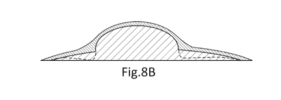
As represented on figure 8B, the at least one coating layer 10 of at least one
coating element may be thicker in the periphery of the surface of a coated
optical
element than in the optical center of said coated optical element.
CA 03116454 2021-04-14
WO 2020/079105 -28- PCT/EP2019/078128
As represented on figure 8C, the at least one coating layer 10 of at least one
coating element may be thicker in the center of the surface of a coated
optical
element than at the edge of the surface of said coated optical element.
With reference to figures 8B and 8C, the dotted lines represents the
modifications to apply to the shape of the optical element to compensate the
modification of the targeted optical function of said optical element induced
by the
coating process. This result in a coating element having a non-uniform
thickness over
said optical element.
The optical elements 8 may be as represented on figures 1, 2 and 9, non-
contiguous optical elements.
In the sense of the disclosure, two optical elements are non-contiguous if for
all the paths linking the two optical elements one may measure at least along
part of
each path the refractive power based on a prescription for the eye of the
person.
According to an embodiment of the disclosure, at least part of the plurality
of
optical elements are placed on at least a ring on the at least one surface of
the lens
element.
According to another embodiment of the disclosure, the plurality of optical
elements are organized on concentric rings on the at least one surface of the
lens
element 2.
With reference to figure 9, the plurality of coated optical elements are
positioned along a set of 11 concentric rings over the entire surface of the
lens
element.
According to other embodiments of the disclosure, the plurality of optical
elements may be organized on different patterns, such as for example square
shaped
pattern.
According to an embodiment of the disclosure, the mean sphere of all the
coated elements 8 placed on a ring is identical. In the sense of the
disclosure, the
term "identical" is to be understood as being within a range of more or less
5% of the
value.
Although being part of the technical knowledge of a person skilled in the art,
reference is made to the definition of mean sphere disclosed in WO
2016/146590.
According to another embodiment of the disclosure, the mean sphere of at
least part of the coated optical elements varies according to the optical
element
CA 03116454 2021-04-14
WO 2020/079105 -29- PCT/EP2019/078128
location on the lens element, more specifically according to the distance of
the
optical element from the geometrical center of the lens element.
According to an embodiment of the disclosure, the mean sphere of at least
part of the coated optical element increases from the center to the edge of
the lens
element.
According to an embodiment of the disclosure, the mean sphere of at least
part of the coated optical element decreases from the center to the edge of
the lens
element.
According to another embodiment of the disclosure, the mean sphere of at
least part of the coated optical element increases from the center to the edge
of the
lens element.
According to an embodiment of the disclosure illustrated on figure 10, the
coated optical elements are contiguous.
In the sense of the disclosure two optical elements are contiguous if for at
least one path linking the two optical elements one may not measure along said
at
least one path the refractive power based on a prescription for the eye of the
person.
Advantageously, each of these configurations of coated optical elements
allows providing a balance between slowing down the progression of the
abnormal
refraction of the eye of a person and maintaining acceptable vision
performance
and/or wearing comfort of said person.
The disclosure has been described above with the aid of embodiments
without limitation of the general inventive concept.
Many further modifications and variations will suggest themselves to those
skilled in the art upon making reference to the foregoing illustrative
embodiments,
which are given by way of example only and which are not intended to limit the
scope of the disclosure, that being determined solely by the appended claims.
In the claims, the word "comprising" does not exclude other elements or
steps, and the indefinite article "a" or "an" does not exclude a plurality.
The mere
fact that different features are recited in mutually different dependent
claims does not
indicate that a combination of these features cannot be advantageously used.
Any
reference signs in the claims should not be construed as limiting the scope of
the
disclosure.