Note: Descriptions are shown in the official language in which they were submitted.
CA 03116907 2021-04-16
WO 2020/092781
PCT/US2019/059178
PROPELLING DEVICES FOR PROPELLING THROUGH A MEDIUM, USING
EXTERNAL MAGNETIC STIMULI APPLIED THEREON
BACKGROUND OF THE INVENTION
Reproducible and accurate propulsion of nano-/micro-particles in different
biological
matrices poses a formidable challenge. Controlled motion of a micro robot
(also noted as
"microbot") in a biologically or medically relevant environment depends on
reliable
external force, as well as on the properties of respective nano-/micro-
particles of the
microbot.
Both normal and pathological tissues exhibit distinct biophysical microscale
features,
posing specific requirements on the particle's Shape-, Size-, Surface- and
material-
properties (e.g. Stiffness) ¨ also noted as "4S properties." Accordingly,
there is a need for
microbots that would answer these 4S properties challenges.
SUMMARY OF THE INVENTION
According to some embodiments of the invention, a propelling device and
methods of use
thereof are provided; the device is configured to propel through a medium,
using external
magnetic stimuli applied thereon; the device comprising: a propelling-element
and a magnet
in communication with the propelling element. According to some embodiments,
the
magnet is configured to respond to the applied magnetic stimuli and to rotate
the propelling-
element; the propelling-element is configured to convert rotary motion thereof
into
translation motion, and thereby to propel the device through the medium.
According to some embodiments of the invention, a propelling device is
provided,
configured to propel through a medium, using external magnetic stimuli applied
thereon,
the device comprising:
= a helical spring-like element; and
= a cube, cuboid, prism, ellipsoid, disc-like, cylindrical magnet,
accommodated within
the helical element, wherein their longitudinal axes are aligned.
CA 03116907 2021-04-16
WO 2020/092781
PCT/US2019/059178
According to some embodiments, the magnet is configured to respond to the
applied
magnetic stimuli and to rotate the helical element; and wherein the helical
element is
configured to convert rotary motion thereof into a translation motion along at
least one of:
the longitudinal axis, 2D trajectory, 3D trajectory; and thereby to propel the
device through
the medium.
According to some embodiments one of the following holds true:
= the medium comprises at least one material selected from: viscoelastic
medium,
extracellular matrix, interstitial space, biological compartment, biological
duct,
biological vessel, biological node, biological tissue, biological organ;
= the helical element comprises at least one material having Young's
modulus
stiffness above 1GPa, optionally selected from: Polypropylene, Polystyrene,
high
impact Polystyrene, Acrylonitrile butadiene styrene, Polyethylene
terephthalate,
Polyester, Polyamides (Nylons), Poly (vinyl chloride) (PVC), glass, ceramics,
metals selected from: copper, bronze titanium, titanium related alloys,
stainless
steel, gold;
= the magnet comprises:
_ at least one nickel-plated neodymium optionally selected from:
N35, N38,
N40, N42, N45, N48, N50, N52, and N55; or
_ at least one alternative permanent nano/micro magnet material selected
from: samarium cobalt (SmCo), alnico, ceramic, ferrite.
According to some embodiments, the front end of the helical element comprises
a sharp
and/or chiseled tip.
According to some embodiments, the magnet is accommodated at a front section,
at a center
section, or at a back section of the helical element.
According to some embodiments, the magnet is encased with a layer of titanium
vessel.
According to some embodiments, at least part of the device is covered with- or
embedded
into a matrix that contains- an imaging agent, configured to facilitate
visualization; the
imaging agent optionally comprising at least one of: Rhodamine B, Fluorescein,
2
CA 03116907 2021-04-16
WO 2020/092781
PCT/US2019/059178
microbubbles, microdefects, mesoporous silica nano- and micro- particles, and
Upconversion Phosphors.
According to some embodiments, the magnet is fixed to the helical element,
optionally via
an adhesive material comprising at least one of: epoxy, acrylics,
polyurethane, UV curable,
and cyanoacrylate based materials.
According to some embodiments, the adhesive material is incorporated with
mesoporous
nano- or micro- silica particles, configured to enhance contrast under
ultrasound radiation.
According to some embodiments:
= the helical element comprises:
_ outer diameter ranging between 0.66 - 1.2mm;
_ inner diameter ranging between 0.3 - 1.1mm;
_ pitch length ranging between 0.5 - 2.2mm;
_ length ranging between 1 - 5.6mm;
= the magnet comprises:
_ diameter ranging between 0.3 - 0.8mm;
_ length ranging between 0.5 - 1.5mm.
According to some embodiments od the invention, a propelling device is
provided,
configured to propel through a medium, using external magnetic stimuli applied
thereon,
the device comprising:
= a screw-like element characterized by conical- or cylindrical- core and a
helical
ridge;
= a cylindrical magnet, accommodated within a hole drilled in the
cylindrical core,
wherein their longitudinal axes are aligned.
According to some embodiments, the magnet is accommodated at a front section
or a back
section of the cylindrical core.
According to some embodiments, magnet is configured to respond to the applied
magnetic
stimuli and to rotate the helical element; and wherein the screw-like element
is configured
to convert rotary motion thereof into translation motion along at least one
of: the
3
CA 03116907 2021-04-16
WO 2020/092781
PCT/US2019/059178
longitudinal axis, 2D trajectory, 3D trajectory; and thereby to propel the
device through the
medium.
According to some embodiments, one of the following holds true:
= the medium comprises at least one material selected from: viscoelastic
medium,
extracellular matrix, interstitial space, biological compartment, biological
duct,
biological vessel, biological node, biological tissue, biological organ;
= the screw-like element comprises at least one material having Young's
modulus
stiffness above 1GPa, optionally selected from: Polypropylene, Polystyrene,
high
impact Polystyrene, Acrylonitrile butadiene styrene, Polyethylene
terephthalate,
Polyester, Polyamides (Nylons), Poly (vinyl chloride) (PVC), glass, ceramics,
metals selected from: copper, bronze titanium, titanium related alloys,
stainless
steel, gold;
= the magnet comprises:
_ at least one nickel-plated neodymium optionally selected from: N35,
N38, N40,
N42, N45, N48, N50, N52, and N55; or
_ at least one alternative permanent nano/micro magnet material selected from:
samarium cobalt (SmCo), alnico, ceramic, ferrite.
According to some embodiments,
= the screw-like element comprises:
_ length of ranging between 1.1 - 1.7mm;
_ outer diameter ranging between 0.57 - 0.65mm;
_ inner diameter ranging between 0.38 - 0.5mm;
_ pitch ranging between 0.34 - 0.60mm;
_ the hole diameter ranging between 0.2 - 0.4mm;
= the magnet comprises:
_ diameter ranging between 0.2 - 0.5mm;
_ length ranging between 0.5 - 1.5mm.
According to some embodiments of the invention, a propelling device is
provided,
configured to propel through a medium, using external magnetic stimuli applied
thereon,
the device comprising:
4
CA 03116907 2021-04-16
WO 2020/092781
PCT/US2019/059178
= a propelling element comprising:
_ a drill-bit-like element or a chisel-like, configured to vacate the
surrounding
medium as it rotates through; or
_ a screw-like element, characterized by a cylindrical core and a
helical ridge; or
_ a twisted-ribbon-like element;
= a cylindrical magnet, attached to the back end of the propelling element,
wherein
their longitudinal axes are aligned.
According to some embodiments, the diameter of the cylindrical magnet equals
to- or
smaller then- the outer diameter of the propelling element.
According to some embodiments, the magnet is attached to the back end of the
propelling
element via an adhesive material, optimally comprising at least one of: epoxy,
acrylics,
polyurethane, UV curable, and cyanoacrylate based materials.
According to some embodiments, the magnet is configured to respond to the
applied
magnetic stimuli and to rotate the propelling element; and wherein the
propelling element
is configured to convert rotary motion thereof into translation motion along
at least one of:
the longitudinal axis, 2D trajectory, 3D trajectory; and thereby to propel the
device through
the medium.
According to some embodiments, one of the following holds true:
= the medium comprises at least one material selected from: viscoelastic
medium,
extracellular matrix, interstitial space, biological compartment, biological
duct,
biological vessel, biological node, biological tissue, biological organ;
= the propelling element comprises at least one material having Young's
modulus
stiffness above 1GPa, optionally selected from: Polypropylene, Polystyrene,
high
impact Polystyrene, Acrylonitrile butadiene styrene, Polyethylene
terephthalate,
Polyester, Polyamides (Nylons), Poly (vinyl chloride) (PVC), glass, ceramics,
metals selected from: copper, bronze titanium, titanium related alloys,
stainless
steel, gold;
= the magnet comprises:
CA 03116907 2021-04-16
WO 2020/092781
PCT/US2019/059178
- at least one nickel-plated neodymium optionally selected from: N35, N38,
N40, N42, N45, N48, N50, N52, and N55; or
- at least one alternative permanent nano/micro magnet material selected
from: samarium cobalt (SmCo), alnico, ceramic, ferrite.
According to some embodiments,
= the device comprises:
- length of ranging between 1.0 - 3.3mm;
_ propelling element's outer diameter ranging between 0.5 - 1.5mm;
_ propelling element's inner diameter ranging between 0.2 - 0.85mm;
_ propelling element's pitch ranging between 0.44 - 0.81mm;
= the magnet comprises:
- diameter ranging between 0.2 - 0.6mm;
_ length ranging between 0.5 - 1.5mm.
According to some embodiments of the invention, a propelling device is
provided,
configured to propel through a medium, using external magnetic stimuli applied
thereon,
the device comprising:
= a tube, characterized by a carved helical-like front section;
= a cylindrical magnet, accommodated within the bore of the tube, at it's
back section,
wherein their longitudinal axes are aligned.
According to some embodiments, the magnet is configured to respond to the
applied
magnetic stimuli and to rotate the tube; and wherein the tube's carved helical-
like front
section is configured to convert rotary motion thereof into translation motion
along at least
one of: the longitudinal axis, 2D trajectory, 3D trajectory; and thereby to
propel the device
through the medium.
According to some embodiments, one of the following holds true:
= the medium comprises at least one material selected from: viscoelastic
medium,
extracellular matrix, interstitial space, biological compartment, biological
duct,
biological vessel, biological node, biological tissue, biological organ;
6
CA 03116907 2021-04-16
WO 2020/092781
PCT/US2019/059178
= the tube comprises at least one material having Young's modulus stiffness
above
1GPa, optionally selected from: Polypropylene, Polystyrene, high impact
Polystyrene, Acrylonitrile butadiene styrene, Polyethylene terephthalate,
Polyester,
Polyamides (Nylons), Poly (vinyl chloride) (PVC), glass, ceramics, metals
selected
from: copper, bronze titanium, titanium related alloys, stainless steel, gold;
= the magnet comprises:
_ at least one nickel-plated neodymium optionally selected from:
N35, N38,
N40, N42, N45, N48, N50, N52, and N55; or
_ at least one alternative permanent nano/micro magnet material selected
from: samarium cobalt (SmCo), alnico, ceramic, ferrite.
According to some embodiments:
= the tube comprises:
_ length of ranging between 1.7 - 3.5mm;
_ outer diameter ranging between 0.76 - 0.83mm;
_ inner diameter ranging between 0.3 - 0.6mm;
_ pitch of the helical section ranging between 0.51 ¨ 1.50mm;
= the magnet comprises:
_ diameter ranging between 0.3 - 0.6mm;
_ length ranging between 0.5 - 3.0mm.
According to some embodiments of the invention, a propelling device is
provided,
configured to propel through a medium, using external magnetic stimuli applied
thereon,
the device comprising:
= a wedge-like element, configured to pierce through the medium as it
translates
through; and
= a magnet, attached to the back end of the wedge-like element, wherein the
magnet's
longitudinal axis is parallel to the wedge-like element's back end wall.
According to some embodiments, the magnet is attached to the back end of the
wedge-like-
element via an adhesive material, optimally comprising at least one of: epoxy,
acrylics,
polyurethane, UV curable, and cyanoacrylate based materials.
7
CA 03116907 2021-04-16
WO 2020/092781
PCT/US2019/059178
According to some embodiments, the magnet is configured to respond to the
applied
magnetic stimuli and to translate the wedge-like-element, and thereby to
propel the device
through the medium.
According to some embodiments, one of the following holds true:
= the medium comprises at least one material selected from: viscoelastic
medium,
extracellular matrix, interstitial space, biological compartment, biological
duct,
biological vessel, biological node, biological tissue, biological organ;
= the wedge-like element comprises at least one material having Young's
modulus
stiffness above 1 GPa, optionally selected from: Polypropylene, Polystyrene,
high
impact Polystyrene, Acrylonitrile butadiene styrene, Polyethylene
terephthalate,
Polyester, Polyamides (Nylons), Poly (vinyl chloride) (PVC), glass, ceramics,
metals selected from: copper, bronze titanium, titanium related alloys,
stainless
steel, gold;
= the magnet comprises:
_ at least one nickel-plated neodymium optionally selected from: N35, N38,
N40,
N42, N45, N48, N50, N52, and N55; or
_ at least one alternative permanent nano/micro magnet material selected from:
samarium cobalt (SmCo), alnico, ceramic, ferrite.
According to some embodiments:
= the wide-like-element comprises:
_ side length ranging between 0.2 - 2.5mm;
_ height ranging between 0.2 - 5.0mm;
_ head angle ranging between 25 - 75deg;
= the magnet comprises:
_ diameter ranging between 0.2 - 0.6mm;
_ length ranging between 0.2 - 3.0mm.
BRIEF DESCRIPTION OF THE DRAWINGS
The subject matter regarded as the invention is particularly pointed out and
distinctly
claimed in the concluding portion of the specification. The invention,
however, both as to
8
CA 03116907 2021-04-16
WO 2020/092781
PCT/US2019/059178
organization and method of operation, together with objects, features, and
advantages
thereof, may best be understood by reference to the following detailed
description when read
with the accompanying drawings in which:
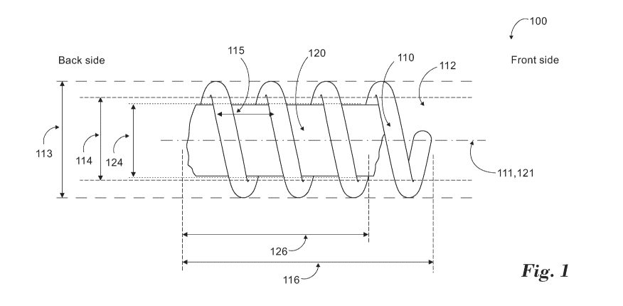
Fig. 1 demonstrates an example for a propelling device having a helical spring-
like element,
according to various embodiments of the invention;
Figs. 2A, 2B, 2C and 2D demonstrate four more examples for a propelling device
having a
helical spring-like element, according to various embodiments of the
invention;
Fig. 3 demonstrates an example for a propelling device comprising a screw-like
element,
according to various embodiments of the invention;
Figs. 4A, 4B, 4C and 4D demonstrate four examples for a propelling device
having a magnet
attached to a propelling element, according to various embodiments of the
invention;
Fig. 5 demonstrates another example for a propelling device having a magnet
attached to a
propelling element, according to various embodiments of the invention;
Fig. 6 demonstrates an example for a propelling device having a carved helical
section,
according to various embodiments of the invention;
Fig. 7 demonstrates an example for a propelling device having a wedge-like
element,
according to various embodiments of the invention;
Fig. 8 demonstrates an example for a method of inserting a propelling device
into an
anesthetized rat's liver, according to various embodiments of the invention;
Fig. 9 demonstrates an example for a method and an apparatus configured for
external
stimuli and control of a propelling device, according to various embodiments
of the
invention;
Fig. 10 demonstrates an example for a use of the apparatus for external
stimuli and control
of a propelling device, according to various embodiments of the invention;
Figs. 11A, 11B and 11C demonstrate test results for levels of representative
liver enzymes
(ALT, AST) at days 0, 1 and 14 post-treatment with SKC8 particle, according to
various
embodiments of the invention;
9
CA 03116907 2021-04-16
WO 2020/092781
PCT/US2019/059178
Figs. 12A, 12B and 12C demonstrate test results for levels of representative
liver enzymes
(ALT, AST) at days 0, 1 and 14 post-treatment with Hovo2 particle, according
to various
embodiments of the invention;
Figs. 13A, 13B, 13C, 13D and 13E demonstrate levels of representative liver
enzymes
(ALT, AST) at days 0, 1 and 14 post-treatment with Hovo2 particle and 20G
needle,
according to various embodiments of the invention;
Figs. 14A, 14B, 14C and 14D demonstrate images of liver damage of rat treated
with Hovo2
microbot taken at lhr, 3hr, 24hr, and 14 days, respectively;
Figs. 15A and 15B demonstrate liver injury score, observed in all sample's vs.
time after
treatment;
Fig. 16 demonstrates ultrasound image of spring based microbot, processed
using image
tracking software; and
Fig. 17 demonstrates a retraction device, which uses an Eppendorf tube with an
ND52
0.8mm magnet located on the tip.
It will be appreciated that for simplicity and clarity of illustration,
elements shown in the
figures have not necessarily been drawn to scale. For example, the dimensions
of some of
the elements may be exaggerated relative to other elements for clarity.
Further, where
considered appropriate, reference numerals may be repeated among the figures
to indicate
corresponding or analogous elements.
DETAILED DESCRIPTION OF THE PRESENT INVENTION
In the following detailed description, numerous specific details are set forth
in order to
provide a thorough understanding of the invention. However, it will be
understood by those
skilled in the art that the present invention may be practiced without these
specific details.
In other instances, well-known methods, procedures, and components have not
been
described in detail so as not to obscure the present invention.
Reproducible and accurate propulsion of nano-/micro- particles in different
biological
matrices poses a formidable challenge. Controlled motion of micro robot (also
noted as
"microbot") in a biologically or medically relevant environment depends on
reliable
CA 03116907 2021-04-16
WO 2020/092781
PCT/US2019/059178
external force, as well as on the properties of respective nano-/micro-
particles of the
microbot.
Both normal and pathological tissues exhibit distinct biophysical microscale
features,
posing specific requirements on the particle's Shape-, Size-, Surface- and
material-
properties (e.g. Stiffness) ¨ (also noted as "4S properties"). The various
embodiments of the
currently provided invention are configured to answer these challenges,
exhibiting varying
4S properties, as described in the following.
According to various embodiments of the present invention, a platform for
active and
accurate delivery of microparticles, is provided, endowed with diverse
therapeutic load(s)
and/or diagnostics to a specific location using external stimuli.
It is contemplated that propelling devices and microbots according to
embodiments of the
present invention will include particles described in International Patent
Application
PCT/US2018/030960 filed on May 3, 2018 and titled "METHODS AND SYSTEMS TO
CONTROL PARTICLES AND IMPLANTABLE DEVICES," which is hereby
incorporated by reference in its entirety. Briefly, such particles are
microelectromechanical
(MEM) propelling devices, which comprise: (i) an actuator; (ii) a responsive
element; (iii)
a sensor; and (iv) an electronic circuit; wherein: said actuator controls and
operates said
responsive element; said electronic circuit controls said actuator; and said
sensor receives
signals transmitted by a remote unit. It is also contemplated that propelling
devices and
microbots according to embodiments of the present invention will be included
in the
platforms described in International Patent Application PCT/US2018/030960.
Briefly, such
platforms comprise the following modules: (a) one or more propelling devices
or microbots
described herein and comprising embedded logic and various MEM components; (b)
a
delivery and/or retraction module, configured to deliver and/or retract the
devices; (c) an
external signal generator; (d) an imaging module, configured to monitor said
particles; and
(e) an integration module configured to receive inputs from and to provide
output control
commands to other modules; wherein: said modules are configured to
interact/communicate
with each other; and said modules are internally controlled, externally
controlled or both;
and wherein said platform provides active, pre-determined, fully controlled,
precise delivery
of said devices in vitro, in vivo, and/or in a patient.
11
CA 03116907 2021-04-16
WO 2020/092781
PCT/US2019/059178
Reference is now made to Figs. 1, 2A, 2B, 2C and 2D, which demonstrate
(helical) "spring
based" propelling microbots, as provided according to some embodiments of the
invention,
which are configured to provide a corkscrew-like motion, thereby an effective
propulsion
motion through varying viscoelastic media.
According to some embodiments, a propelling device (100) is provided,
configured to
propel through a medium, using external magnetic stimuli applied thereon, the
device
comprising:
= a helical spring-like element (110); and
= a cube, cuboid, prism, ellipsoid, disc-like, cylindrical magnet (120),
accommodated within the helical element, wherein their longitudinal axes
(111,121) are aligned.
According to some embodiments, the magnet is configured to respond to the
applied
magnetic stimuli and to rotate the helical element; and the helical element is
configured to
convert rotary motion thereof into a translation motion along at least one of:
the longitudinal
axis, 2D trajectory, 3D trajectory, and thereby to propel the device through
the medium.
According to some embodiments, the medium (not shown), mentioned above and/or
in the
following, comprises at least one of: viscoelastic medium, extracellular
matrix, interstitial
space, biological compartment, biological duct, biological vessel, biological
node,
biological tissue, biological organ.
According to some embodiments, the front end of the helical element comprises
a sharp
and/or chiseled tip (112).
According to some embodiments, the magnet is accommodated at a center section
of the
helical element (as demonstrated in Figs 2A-2D), at a front section of the
helical element
(not shown), or at a back section of the helical element (as demonstrated in
Fig. 1). It is
noted that the terms "front" and "back" are relative to the designed motion
direction of the
microbot particle. According to some embodiments, the location and the length
of the
magnet is determined based on the medium to propelled in.
12
CA 03116907 2021-04-16
WO 2020/092781
PCT/US2019/059178
According to some embodiments, the magnet is fixed to the helical element,
optionally via
an adhesive material. According to some embodiments, the adhesive material
comprises at
least one of: epoxy, acrylics, polyurethane, UV curable, and cyanoacrylate
based materials.
According to some embodiments, while the spring-based microbots provide
efficient
motion under ultrasonic images, due to the lack of its metallic components,
their signal-to-
noise ratio of ultrasonic responses may be improved. This may become
problematic in vivo
due to copious cavities present in organs of interest. According to some
embodiments, a
solution is provided by incorporating various diameters of mesoporous silica
particles into
the spring-based microbots.
According to such embodiments, the adhesive material is incorporated with
mesoporous
nano- or micro- silica particles, configured to enhance contrast under
ultrasound radiation.
Therefore, a "sonic spring based" microbot is provided.
An example for fabricating such a sonic spring based microbot includes a
fabrication
process which is nearly identical to that of spring-based microbots described
above.
Stainless steel micro-springs of inner diameters ranging from 0.4mm to 1.1mm
with wire
diameters ranging from 0.150mm to 0.255mm were extended with equal force on
each end
until the pitch of the spring was between 0.7mm and 1.5mm. Then, an end of
this extended
spring was clipped off with a nipper plier. Afterwards, an N52 magnet was
inserted within
the extended spring and axially aligned with the spring. A few milligrams (mg)
of
mesoporous silica particles were mixed in with epoxy. This mesoporous silica-
incorporated
epoxy was then applied uniformly around the magnet to affix it to the exterior
spring. Fig.
2B demonstrates a typical sonic spring-based microbot. According to some
further
experiments, when the spring-based microbots were embedded with 1p m
mesoporous silica
particles, there was a significant increase in brightness. This is due to the
air-bubbles present
in silica pore responding to the incident ultrasound.
According to some embodiments, in order to reduce variability in preparing the
spring-
based magnetic particles, microbots that do not require any adhesives, but fit
snugly within
the spring are provided herein. According to such embodiments, the magnet is
encased with
a layer of titanium vessel, before it is inserted into the helical element.
13
CA 03116907 2021-04-16
WO 2020/092781
PCT/US2019/059178
A non-limiting example is demonstrated in Fig. 1, showing an N52 magnet with
an outer
diameter of 0.5 millimeter (mm) and a length of lmm, which was encased in a
thin layer of
titanium vessel. Then, the titanium vessel containing the magnet was
physically inserted
inside the spring (110) with inner diameter of 0.61mm and wire thickness
(diameter) of
0.152mm. The no-adhesive spring-based microbots were examined in freshly
euthanized rat
liver in vivo to exhibit good mobility under rotating magnetic field gradient.
Subsequently,
single microbot, presented in Fig. 1, traversed through various liver sub-
compartments of
eight rats at magnetic field strength of ¨250mT and a gradient of 10 T/m
without any damage
or degradation.
According to some embodiments, at least part of the device is covered with- or
embedded
into a matrix that contains- an imaging agent, configured to facilitate its
visualization ex
vivo or in-vivo. The imaging agent optionally comprises at least one of:
Rhodamine B,
Fluorescein, microdefects, microbubbles, microdefects, mesoporous silica nano-
and micro-
particles, and Upconversion Phosphors.
According to some embodiments, the helical element comprises a material having
Young's
modulus stiffness above 1 Giga Pascal (GPa), optionally selected from:
Polypropylene,
Polystyrene, high impact Polystyrene, Acrylonitrile butadiene styrene,
Polyethylene
terephthalate, Polyester, Polyamides (Nylons), Poly (vinyl chloride) (PVC),
glass, ceramics,
metals, titanium, titanium related alloys, stainless steel, gold.
According to some embodiments, the magnet (mentioned above and/or in the
following)
comprises:
_ at least one nickel-plated neodymium optionally selected from: N35,
N38, N40,
N42, N45, N48, N50, N52, and N55; or
_ at least one alternative permanent nano/micro magnet material selected from:
samarium cobalt (SmCo), alnico, ceramic, ferrite.
According to some embodiments, the helical element comprises:
_ outer diameter (113) ranging between 0.66 - 1.2mm;
_ inner diameter (114) ranging between 0.3 - 1.1mm;
_ pitch (115) length ranging between 0.5 - 2.2mm;
_ length (116) ranging between 1 - 5.6mm.
14
CA 03116907 2021-04-16
WO 2020/092781
PCT/US2019/059178
According to some embodiments, the magnet comprises:
_ outer diameter (124) ranging between 0.3 - 0.8mm;
_ length (126) ranging between 0.5 - 1.5mm.
Examples for "spring-based" microbots: Stainless steel micro-springs of inner
diameters,
ranging from 0.4mm to 1.1mm with wire diameters ranging from 0.150mm to
0.255mm, were
extended with equal force on each end until the pitch of the spring was
between 0.7mm and
1.5mm. Then, an end of this extended spring was clipped off with a nipper
plier. This created
a sharp and chiseled tip for the microbot. Afterwards, a nickel-plated
neodymium 52 (N52)
magnet of varying diameters and lengths (diameters ranging from 0.3mm to 0.8mm
and
lengths ranging from 0.5mm to 1.5mm) were inserted within the extended spring
and were
axially aligned. The distance from the edge of the magnet to the tip of the
spring was
measured to be between 0.3mm and 1.22mm. Once the magnet was aligned with the
spring's
axis, it was fixed to the spring with a small amount of epoxy or cyanoacrylate
and allowed it
to cure for 8 his.
Figs. 2A and 2B are representative images of spring-based particles, where the
magnet was
affixed to the spring with cyanoacrylate and epoxy, respectively. It was
demonstrated that
microbots fixed with epoxy tend to have a more rounded body than those glued
with
cyanoacrylate.
To aid the process of ex vivo and in vivo injection of the microbots into
tissue, where there
is limited visibility, various imaging agents were incorporated onto the
microbots. When
the magnets were glued to the springs using cyanoacrylate, the imaging agent
(e.g.
Rhodamine B, Fluorescein, Upconversion Phosphors) was first dusted on top of
the magnet
and afterwards cyanoacrylate was deposited on top to seal the imaging agents
to the magnet.
This process was repeated three times and after the deposition of third layer,
final layer of
cyanoacrylate was deposited. For the microbots glued with epoxy, the imaging
agents were
added to the epoxy mixture and mixed in prior to applying it on the microbot.
Fig. 2C is a representative image of spring-based microbots that has been
dusted with
Rhodamine B prior to application of cyanoacrylate. Likewise, Fig. 2D shows a
spring-based
microbot that has been affixed with Rhodamine B-suspended epoxy.
CA 03116907 2021-04-16
WO 2020/092781
PCT/US2019/059178
Particle propulsion was tested using both uniform (0.17) and gradient-based
magnetic
devices in order to select best performing system and particles.
(i) In Agar Under Gradient, Rotating Magnetic Field. Spring-based microbots
were
inserted into a piece of agar and subsequently placed at the predetermined
distance
away from the magnetic surface of the propulsion device (ca. 17-20mm away from
the center of the magnet in the gradient magnetic system), where the field
strength is
measured to be around 340mT and its gradient 12T/m. Upon application of
magnetic
field rotation of ¨1Hz, rotation of movement of spring-based microbots were
observed
and their travel time recorded to calculate the average speed. 97% of spring-
based
microbots successfully traversed through agar and the average speed was
0.7mm/sec.
(ii) In Agar Under Uniform, Rotating Magnetic Field. The mobility test results
of the
spring-based microbots showed varying results. The microbots that moved most
efficiently in rotating uniform field tend to move faster than average spring-
based
microbots in rotating gradient field as it is demonstrated in Table 1.
(iii)In Vivo Rat Liver, Rotating Gradient Magnetic Field. One spring-based
microbot
("SKC8") traversed through four different rats' livers in vivo for the purpose
of
preliminary safety testing of the spring-based microbots. Based on injection
position
and retraction point, positive movement was confirmed under magnetic field
strength
of 280mT and a gradient of 8T/m.
Field type Medium Success
Rate 1%) Average Speed (minis) Field Strength (Ti Gradient (Tim)
Uniform Rotating Agar 13.33333331 1,559 0.11 0
Rotating Gradient. Agar 96.66666667 0.724 0.3381 12
Uniform Rotating Rat liver in vivo 0/0 N/A NJA N/A
Rotaing Gradient Rat iiVer. in vivo 4/4 No info 0281 8
Table I Summary a mowity te515 Or spring-based fTliU0b015
Reference is now made to Fig. 3, which demonstrates a "screw-shaped"
propelling
microbot, provided according to some embodiments of the invention. According
to some
embodiments, this configuration closely mimics the shape of a screw, with a
sharp tip and
a base with constant pitch. The screw-shape microbot configured to:
_ reduce the total length of the microbot, thereby minimize damage that may be
caused to the organ of interest; and
_ produce a screw-like motion that aids with propulsion in vivo.
16
CA 03116907 2021-04-16
WO 2020/092781
PCT/US2019/059178
According to some embodiments, a propelling device (200) is provided,
configured to
propel through a medium, using external magnetic stimuli applied thereon, the
device
comprising:
= a screw-like element (210), characterized by a conical-core (not shown)
or a
cylindrical-core (211) and a helical ridge (212);
= a cylindrical magnet (220), accommodated within a hole (213) drilled in
the
cylindrical core, wherein their longitudinal axes (214,224) are aligned.
According to some embodiments, the magnet is accommodated at a back section of
the
cylindrical core. According to some embodiments, the magnet is provided at a
front section
of the cylindrical core (not shown), in such embodiments, the length of the
provided magnet
is smaller than the length of the drilled hole.
According to some embodiments, the magnet is configured to respond to the
applied
magnetic stimuli and to rotate the helical element; and the screw-like element
is configured
to convert rotary motion thereof into translation motion along at least one
of: the
longitudinal axis, 2D trajectory, 3D trajectory; and thereby to propel the
device through the
medium.
According to some embodiments, the screw-like element comprises at least one
material
having Young's modulus stiffness above 1GPa, optionally selected from:
Polypropylene,
Polystyrene, high impact Polystyrene, Acrylonitrile butadiene styrene,
Polyethylene
terephthalate, Polyester, Polyamides (Nylons), Poly (vinyl chloride) (PVC),
glass, ceramics,
metals selected from: copper, bronze titanium, titanium related alloys,
stainless steel, gold.
According to some embodiments, the screw-like element comprises:
_ length (215) of ranging between 1.1 - 1.7mm;
_ outer diameter (216) ranging between 0.57 - 0.65mm;
_ inner diameter (217) ranging between 0.38 - 0.5mm;
_ pitch (218) ranging between 0.34 - 0.60mm;
_ the hole diameter (219) ranging between 0.2 - 0.4mm.
According to some embodiments, the magnet (220) comprises:
_ outer diameter ranging between 0.2 - 0.5mm:
17
CA 03116907 2021-04-16
WO 2020/092781
PCT/US2019/059178
_ length ranging between 0.5 - 1.5mm.
Example for "screw-based" microbot: A screw-like gold casing was fabricated
with a
length of 1.5mm and total width (diameter) of 0.54mm. The pitch of the screw
was measured
to be 0.39mm. Afterwards, a small hole with a diameter of 0.3mm was drilled
into the screw
end. An N52 magnet with a diameter of 0.3mm and length of lmm was inserted
into the
hole. A representative image of such a screw-shaped microbot is provided in
Fig. 3.
Under rotating a magnetic field gradient, when the screw-shaped microbots were
embedded
in agar, the microbots traveled at a comparable speed as those of spring
microbots in agar
under similar conditions. When they were inserted in freshly euthanized rat
liver, however,
the propulsion was slower as compared to the spring-based particles.
Reference is now made to Figs. 4A-4D and Fig. 5, which demonstrate propelling
microbots
comprising a magnet attached to a propelling element, provided according to
some
embodiments of the invention.
Microdrill bits are configured to provide a unique topology optimized to
vacate the
surrounding medium as they rotate through. Due to the limited inner diameter
of the drill
bit core, largest hole that can be drilled without compromising the integrity
is about 0.1mm,
which may be too small to insert any magnets. Therefore, a provided solution
is to attach a
magnet at the base of the microdrill bit.
According to some embodiments, a propelling device (301,304,305), is provided
configured
to propel through a medium, using external magnetic stimuli applied thereon,
the device
comprising:
= a propelling element comprising:
_ a drill-bit-like element (Figs. 4A-4B, 310) or a chisel-like (not shown),
configured to vacate the surrounding medium as it rotates through; or
_ a screw-like element (Figs. 4C-4D, 330), characterized by a cylindrical core
(338) and a helical ridge (339); or
_ a twisted-ribbon-like element (Fig. 5, 340);
18
CA 03116907 2021-04-16
WO 2020/092781
PCT/US2019/059178
= a cube, cuboid, prism, ellipsoid, disc-like, cylindrical magnet (320),
attached to the
back end of the propelling element, wherein their longitudinal axes
(314/334/344,324) are aligned.
According to some embodiments, the diameter (321) of the cylindrical magnet
equals to- or
smaller then- the outer diameter (311/331/341) of the propelling element.
According to some embodiments, the magnet is attached to the back end of the
propelling
element via an adhesive material, optimally comprising at least one of: epoxy,
acrylics,
polyurethane, UV curable, and cyanoacrylate based materials.
According to some embodiments, the magnet is configured to respond to the
applied
magnetic stimuli and to rotate the propelling element; and wherein the
propelling element
is configured to convert rotary motion thereof into translation motion along
at least one of:
the longitudinal axis, 2D trajectory, 3D trajectory; and thereby to propel the
device through
the medium.
According to some embodiments, the propelling element comprises at least one
material
having Young's modulus stiffness above 1GPa, optionally selected from:
Polypropylene,
Polystyrene, high impact Polystyrene, Acrylonitrile butadiene styrene,
Polyethylene
terephthalate, Polyester, Polyamides (Nylons), Poly (vinyl chloride) (PVC),
glass, ceramics,
metals selected from: copper, bronze titanium, titanium related alloys,
stainless steel, gold.
According to some embodiments, the device (301,304,305) comprises:
_ length (351,353,354) of ranging between 1.0 - 3.3mm;
_ propelling element's outer diameter (311,331,341) ranging between 0.5 -
1.5mm;
_ if relevant, propelling element's inner diameter (312,332) ranging
between 0.20 -
0.85mm;
_ propelling element's pitch ranging (315,335,345) between 0.44 - 0.81mm.
According to some embodiments, the magnet (320) comprises:
_ outer diameter ranging between 0.2 - 0.6mm;
_ length ranging between 0.5 - 1.5mm.
19
CA 03116907 2021-04-16
WO 2020/092781
PCT/US2019/059178
Examples for "drill-bit / screw-like" microbots (with back attached magnets):
N52
magnets with a diameter of 0.6mm and length of lmm were attached to two
different types
of tips (propelling elements). First, various configurations of microdrill
bits were purchased
and sent for post processing to laser-cut the drill bit tips to lengths of
2mm. A representative
image of these microdrill tip is provided in Fig. 4A. A second set of tips
were fabricated to
1.5 mm long micro-screws with outer diameter of 0.75 mm and pitches of either
2 turns/mm
or 3 turns/mm (Fig. 4C).
A piece of N52 magnet with an outer diameter of 0.6mm and length of lmm was
dipped into
epoxy and was fixed to the base of either the microdrill bit tips and the
micro-screw tips and
held together by hand for a couple of minutes until they remained stationary.
Afterwards,
the microbots were left in air overnight for curing. Representative images of
microbots
fabricated with micro-drill bit tips and micro-screw tips are presented in
Fig. 4B and Fig.
4D, respectively.
Two drill-bit-based microbots that had been assembled thus far, exhibited
slower movement
in agar under rotating gradient field (under 0.05 mm/s) as compared to the
spring-based
particles.
Reference is now made to Fig. 6, which demonstrates a "carved helix"
propelling, provided
according to some embodiments of the invention.
According to some embodiments, by carving out a hollow metal tube (including
but not
limited to titanium and stainless steel) into a helical shape, it allows one
to control various
physical parameters such as pitch and wire thickness. Furthermore, the use of
thicker
helices, provides more rigidity to the helices, thereby provides more support
during
propulsion.
According to some embodiments, a propelling device (400) is provided,
configured to
propel through a medium, using external magnetic stimuli applied thereon, the
device
comprising:
= a tube (410), characterized by a carved helical-like front section (411);
= a cube, cuboid, prism, ellipsoid, disc-like, cylindrical magnet (420),
accommodated within the bore of the tube, at its back section, wherein their
longitudinal axes (414,424) are aligned.
CA 03116907 2021-04-16
WO 2020/092781
PCT/US2019/059178
According to some embodiments, the magnet is configured to respond to the
applied
magnetic stimuli and to rotate the tube; and wherein the tube's carved helical-
like front
section is configured to convert rotary motion thereof into translation motion
along at least
one of: the longitudinal axis, 2D trajectory, 3D trajectory; and thereby to
propel the device
through the medium.
According to some embodiments, the tube comprises at least one material having
Young's
modulus stiffness above 1GPa, optionally selected from: Polypropylene,
Polystyrene, high
impact Polystyrene, Acrylonitrile butadiene styrene, Polyethylene
terephthalate, Polyester,
Polyamides (Nylons), Poly (vinyl chloride) (PVC), glass, ceramics, metals
selected from:
copper, bronze titanium, titanium related alloys, stainless steel, gold.
According to some embodiments, the tube comprises:
_ length (415) of ranging between 1.7 - 3.5mm;
_ outer diameter (412) ranging between 0.76 - 0.83mm;
_ inner diameter (413) ranging between 0.3 - 0.6mm;
_ pitch (416) of the helical section ranging between 0.51 - 1.50mm.
According to some embodiments, the magnet (420) comprises:
_ outer diameter ranging between 0.3 - 0.6mm;
_ length ranging between 0.5 - 3.0mm.
An example for a carved-helix microbot is provided in Fig. 6, where an N52
magnet
(hidden, 420) was inserted into the base of a metallic tube (410) with an
inner diameter that
matches the outer diameter of the magnet. Subsequently, the tip of the
metallic tube was
carved out (411) with a metal cutting device such as diamond tip cutter,
laser, CNC tool,
and other micro-cutting techniques to create helices. A representative image
of the carved-
helix microbot (400) is provided in Fig 6.
A representative carved-helix microbot was tested and traveled at a speed of
¨0.5mm/s in
agar; notes: (1) the speed was estimated and not rigorously measured, (2) the
test was
conducted with Macho 3.0 and therefore cannot be directly compared with speeds
of other
microbots. According to the test's results, the tube's length and the ratio
between the helical
section and smooth magnetic casing influences on microbot mobility.
21
CA 03116907 2021-04-16
WO 2020/092781
PCT/US2019/059178
According to some embodiments, and as demonstrated in Fig. 7, a propelling
device (500)
is provided, configured to propel through a medium, using external magnetic
stimuli applied
thereon, the device comprising:
= a wedge-like element (510), configured to pierce through the medium as it
translates through; and
= a magnet (520), attached to the back end of the wedge-like element,
wherein the
magnet's longitudinal axis (524) is parallel to the wedge-like element's back
end
wall.
According to some embodiments, the magnet is attached to the back end of the
wedge-like-
element via an adhesive material, optimally comprising at least one of: epoxy,
acrylics,
polyurethane, UV curable, and cyanoacrylate based materials.
According to some embodiments, the magnet is configured to respond to the
applied
magnetic stimuli and to translate the wedge-like-element, and thereby to
propel the device
through the medium.
According to some embodiments, the wedge-like element comprises at least one
material
having Young's modulus stiffness above 1GPa, optionally selected from:
Polypropylene,
Polystyrene, high impact Polystyrene, Acrylonitrile butadiene styrene,
Polyethylene
terephthalate, Polyester, Polyamides (Nylons), Poly (vinyl chloride) (PVC),
glass, ceramics,
metals selected from: copper, bronze titanium, titanium related alloys,
stainless steel, gold.
According to some embodiments, the wide-like-element (520) comprises:
_ side length (511) ranging between 0.2 - 2.5mm;
_ height ranging (512) between 0.2 - 5.0mm;
_ head angle (513) ranging between 25 - 75deg;
According to some embodiments, the magnet (520) comprises:
_ outer diameter ranging between 0.2 - 0.6mm;
_ length ranging between 0.2 - 3.0mm.
According to some embodiments, the above-mentioned magnets can comprise a
cylinder, a
ring, or a tube configuration. It is noted herein that when the "outer"
diameter of the magnet
22
CA 03116907 2021-04-16
WO 2020/092781
PCT/US2019/059178
is referred to, it may also refer to a cylinder's diameter; or if the magnet's
diameter is
mentioned, if relevant it may refer to the outer diameter.
Microbots dimension examples: The above-mentioned propelling devices were test
with
various shapes and surfaces. Further, within same shape and surface
properties, various
dimensions were tested to demonstrate the effects that physical dimensions
have on
microbot mobility. Table 2 provides the dimension ranges per class of
microbot.
Bor. Type Length (nun) Or Diameter (turn') Diner Diameter (mm)
Ptch (mm)
Spring-Eased Microbots 1.4-5.6 0.66-1.2 0.41-1 0.67-2.17
Screw-Shaped btierob0 1.1-17 0.57-0.65 0.3 0 -0.45
Prefabricated Pats 2.6-3.3 0.71-0.83 0.41-0.64 10.44-0.81
No Adhesive Spring-Based. Wertabots 1.74.2 0.94-1.3 0.67-0.83 1
0.43-0.82
C.arved Helix Micrabots 1.7-3.4 O76-3 0.50-0.55
10.51-1.5
Sonic...Sprig-Based Mierobots 0.66-1.2 0.41-1 0.67-2.17
Side Length (mm) Height (mm) Head Are (deg)
Wedge-Shaped Microbots 2.6 681
Table 2: range of dimensions
Tests and results
Highly localized and patient-specific treatment of multiple diseases,
including cancer is an
emerging strategy due to its enhanced clinical efficacy-safety outcome. A
platform was
provided for active and accurate delivery of microparticles endowed with
diverse
therapeutic load(s) and/or diagnostics to a specific location using external
stimuli. In these
tests, tissue damage was investigated, caused by representative devices or a
needle (positive
control) in vivo. The propulsion of the currently provided particles through
the liver tissue
was safe and well tolerated in both mice and rats (N=40 total). No significant
differences
were detected in the livers of animals treated with the needle or the current
particles.
Notably, all treated rodents (mice/rat) survived and behaved normally. liver
recovery was
observed and confirmed complete, by day 14 post-treatment using both histology
and
representative biomarkers (ALT/AST).
The ability to deliver drugs through diverse heterogeneous tissue in a highly
controlled and
safe manner both spatially and longitudinally is anticipated to enhance safety-
efficacy
profile of multiple therapeutic agents and to address patient-specific
conditions. The focus
of the currently provided technology is active and precise delivery of diverse
therapeutics
and/or diagnostics agents to a tissue of interest including liver. The
technology is likely to
become a standalone approach or supplement the existing standards of care
suitable for the
23
CA 03116907 2021-04-16
WO 2020/092781
PCT/US2019/059178
treatment of localized conditions including but not limited to tumors,
inflammation, chronic
pain, eye and/or muscle degenerative disorders and bacterial infections.
Towards this goal,
a multimodal platform was developed that includes magnetic propulsion,
versatile
microparticles, imaging-/image- analysis and particle delivery and retraction
modules.
Notably, the provided particle is capable of delivering diverse payloads
including drugs and
diagnostics, both small molecules and biologics to remote, hard to reach
locations in the
human body in a minimally invasive manner. The currently provided
microparticles
(microbots) can move with high degree of accuracy in a variety of biological
media
including liver, gastric, vitreous tissues and deliver diverse targeted
payloads to treat
affected areas of up to 7 cm3 in volume using a single device.
In the initial proof-of-concept studies, hepatocellular carcinoma (HCC) were
selected as the
therapeutic focus. HCC is the most common type of primary liver cancer in
adults and is
the most common cause of death in people with liver cirrhosis. While there are
a number of
accepted cytotoxic drugs (e.g., doxorubicin), targeted drugs (e.g.,
NexavarTm), as well as
novel immuno-oncology therapies (e.g., IpilimumabTm), these drugs rarely
result in durable
benefit and/or may result in serious systemic side effects. While several drug
delivery
systems have been proposed and developed, these agents are still administered
systemically
and have not met their potential due to multiple challenges including
inadequate efficacy.
In the series of experiments described herein, preliminary safety studies were
conducted in
rodents (N=40, 36 rats and 4 mice) aimed at assessment of the general liver
safety/toxicity
associated with the particle motion through the organ. Specifically, two
distinct
representative microbots were used to propel through the designated liver
compartments,
analyzed time-dependent (1hr, 3hrs, 24hrs and 14 days) liver damage and
compared it to
positive control animal group treated with injection needle.
The examined data suggests that the currently provided particles traversed
reliably,
reproducibly and safely through the liver without causing general tissue
damage.
Longitudinal studies of the liver toxicity further indicate that both needle
and microparticle
treatment caused rapid and transient changes to the liver histology 3hrs post-
treatment. The
pathology was dramatically reduced by day 7 and the liver tissue was
completely recovered
at day 14 post-treatment. These acute changes and recovery of the liver tissue
by day 14
24
CA 03116907 2021-04-16
WO 2020/092781
PCT/US2019/059178
were further corroborated via measurements of representative blood biomarkers
ALT and
AST.
Visualizing and tracking movement of the microbots, through the liver, to
estimate the
accuracy of propulsion, were enabled using ultrasound imaging. Moreover, a
prototype
device was also designed, which is suitable for safe and accurate delivery and
retraction of
the particles, and these experiments were validated in both ex vivo and in
vivo in murine
models.
The primary purpose of the study was to evaluate the ability for the provided
particle to
move through a heterogeneous tissue (the liver) without causing non-transient
toxicity.
Primary test goals of the study:
a. to propel a particle through organ/tissue of therapeutic interest (e.g.,
liver) in vivo
using external magnetic stimuli followed by histopathological assessment of
tissue
damage;
b. to examine the initial time course (14 days) of tissue regeneration post-
traumatic
treatment with the particle(s) vs. needle (same outer diameter) as a positive
control;
Secondary test goals of the study:
c. to visualize and track movement of the devices through tissue such as
liver.
d. to determine distance traveled by the particle.
e. to develop a protocol for preliminary particle insertion-retraction
protocol suitable
for further optimization.
Procedure:
a) Animals: 6-8 weeks old female Sprague-Dawley (SD) rats (N=36) and 10 weeks
old male BALBc mice (N=4).
b) Administration of Anesthesia (Isoflarane): The rat was anesthetized using
5%
isoflurane in 100% 02 with sedation to be confirmed with a toe pinch. The
anesthesia was maintained at 1-2% isoflurane by inhalation and ventilation
throughout the procedure. The surgical area was prepared by shaving and
removing
hair (if needed), cleansing the skin by wiping with 70% ethanol.
c) Intra-hepatic Implantation of the particle: Following anesthesia induction,
a
midline incision was made in the skin of the abdomen and a second incision was
CA 03116907 2021-04-16
WO 2020/092781
PCT/US2019/059178
made into the peritoneal cavity using blunt scissors. Insertion and retraction
of the
particle was performed on the surgical table. A particle was inserted
completely into
either Right Medial Lobe or Left Lateral Lobe of the liver using plastic
forceps. Fig.
8 demonstrates particle insertion in the liver (right medial lobe) of
anesthetized rat
using plastic forceps. Needle (20G, ca. 0.91mm outer diameter) puncture was
used
as a positive control to assess the liver damage. The puncture was performed
via the
open-wound procedure to emulate the particle insertion sequence or in situ
through
skin.
d) External Rotating Magnets: After inserting the particle, the anesthetized
rat was
moved to a device platform next to the external magnets. Figs. 9 and 10
demonstrate
an external propulsion platform, based on rotating permanent magnets;
demonstrated
are: the rotating magnets' set-up; the anesthetized animal; a platform for the
animal;
and an US probe. The position of the rat was adjusted so that the inserted
particle is
facing the center of the magnet at a predetermined distance (-20mm) using the
proprietary fixed magnets platform (as in Figs. 9 and 10). The particle was
initiated
and propelled using the external rotating magnets while being continuously
observed
as the device traversed the liver. Once the particle was ready to exit the
liver as
evidenced via visual observation, the rotating magnet was stopped. The animal
was
moved to the surgical table to retrieve the particle using Nd52 micromagnet
(0.8 X
2mm) attached to a plastic holder. Fig. 10 demonstrates relative position of
the rat to
the magnet; shown are: the surface of magnetic set-up, and approximate
particle
position. The distance traveled by the particle in the liver was measured
using
calipers (5-8mm on average). The peritoneal cavity was closed post-procedure
using
nylon or polypropylene sutures. The animal was returned to the individual cage
to
recover with ad libitum access to food and water. Generally, the recovery from
anesthesia took 25-30 min. All animals were monitored every 15min post-surgery
for ca. 3hrs to ascertain overall well-being and normal physiological
behavior.
Notably, no animals were lost due to the procedure in either control (needle)
or
particle test groups. Moreover, all test animals seemed to have recovered
completely
within lhr post procedure.
Study design, group 1:
26
CA 03116907 2021-04-16
WO 2020/092781 PCT/US2019/059178
Bleeds on Day 14
No. #Animals Particle
Day 0, 1 and 14 Liver Histology
SKC8
1 4 Yes Yes
(Fig. 2C)
Hovo2
2 3 Yes Yes
(Fig. 1)
Table 3
Blood and liver tissue collection: On Day 0, Day 1 and Day 14 post-procedure
blood was
collected by tail vein for measuring representative liver enzymes (ALT and
AST, selected
as dynamic markers based on the initial calibration studies). On Day 14, a
specific liver
tissue was collected (area traversed by the particle) for histology (H&E,
hematoxylin and
eosin staining).
Study design, group 2:
Needle / Time # Bleeds on Day 0, 1 Liver
Particle Point Animals and 14 Histology
1 Hovo2 lhr 3 No Yes
20G needle No
2 lhr 3 Yes
open wound
3 Hovo2 3hrs 4 No Yes
20G needle 3hrs No
4 3 Yes
open wound
Hovo2 24hrs 4 No Yes
20G needle No
6 24hrs 4 Yes
open wound
7 Hovo2 14 days 5 Yes Yes
20G needle Yes
8 14 days 3 Yes
open wound
Table 4
Liver tissue collection: lhr, 3hrs, 24hrs and 14 days post-procedure, liver
tissue (area
traversed by the particle) was collected for histology (H&E, hematoxylin and
eosin
staining).
Results for diverse particles (SKC8 and Hovo2): In the toxicity assessment
tests, several
representative particles were used that illustrate at least two diverse
designs including 'string
based particle' with a magnet accommodated in the center of the spring (SKC8),
as
27
CA 03116907 2021-04-16
WO 2020/092781 PCT/US2019/059178
demonstrated in Fig. 2C and 'spring based particle' with a magnet accommodated
in the
back of the spring (Hovo2), as shown in Fig. 1. Particles design and
dimensions are
summarized in Table 5.
Particle Length Outer Diameter Inner Diameter
Pitch
(mm) (mm) (mm) (mm)
Hovo2 (Fig. 1) 2.0 0.97 0.57 0.5
SKC8 (Fig. 2C) 2.8 0.66 0.38 1.6
Table 5
SKC8 blood ALT and AST levels on Day 0, 1 and 14: No significant changes were
observed in blood ALT and AST levels over 14 days following the particle
insertion in
control vs particle treated animals. AST levels were transiently elevated day
1 post-
procedure but returned to normal at day 14. Figs. 11A-11C demonstrate levels
of
representative liver enzymes (ALT, AST) at days 0, 1 and 14 post-treatment
with SKC8
particle; Fig. 11A demonstrates overall profile of liver enzymes, Figs. 11B
and 11C
demonstrate individual profile for the liver enzymes ALT and AST,
respectively, where
each differently colored circle represents an individual animal, N of 4
animals.
Hovo2 blood ALT and AST levels on Day 0, 1 and 14: For the Hovo2 particle
propulsion
studies, significant changes in both ALT (56 vs. 82 IU/L) and AST (119 vs. 186
IU/L) were
observed on Day 1 following particle insertion. On day 14, ALT and AST levels
were
similar to day 1 levels and were not significant. Figs. 12A-12C demonstrate
test results for
levels of representative liver enzymes (ALT, AST) at days 0, 1 and 14 post-
treatment with
Hovo2 particle; Fig. 12A demonstrates overall profile of liver enzymes; Figs.
12B and 12C
demonstrate individual profile for the liver enzymes ALT and AST,
respectively, where
each differently colored circle represents an individual animal, N of 3
animals.
Time course study - Hovo2 vs. Needle controls blood ALT and AST levels on Day
0, 1
and 14: As anticipated, in the Hovo2 and the positive control experiments
(using 20G
needle, internal diameter of 0.6mm, outer diameter of 0.91mm), blood values
for ALT and
AST were higher on Day 1 compared to Day 0, presumably due to acute local
trauma
(Ogawa et al, Healing of focal injury in rat liver. American Journal of
Pathology (1985)
119: 158-167).
28
CA 03116907 2021-04-16
WO 2020/092781
PCT/US2019/059178
Figs. 13A-13E demonstrate levels of representative liver enzymes (ALT, AST) at
days 0, 1
and 14 post-treatment with Hovo2 particle (N=5) and 20G needle (N=3); Fig. 13A
demonstrates overall profile of liver enzymes; Figs. 13B and 13C demonstrate
individual
profile for Hovo2 (ALT and AST, respectively); and Figs. 13D and 13E
demonstrate
individual profile for 20G needle group (where each differently colored circle
represents
individual animal, N of 5 for Hovo2 group and N of 3 for 20G needle group).
Liver injury histology data. In general, livers collected from both the
particle (Hovo2) and
needle (20G) treated animals at lhr, 3hrs and 24hrs post-procedure exhibited
similar organ
lesions including acute hepatic necrosis, hemorrhage, edema, neutrophilic
inflammation and
capsule damage. Interestingly, animals in the t = 3hrs and 24hrs post
treatment groups
exhibited more pronounced histopathological markers of the liver damage vs.
lhr cohort, as
evidenced by hepatic necrosis, edema, inflammation, hemorrhage and capsule
damage. Day
14 post-treatment animals consistently exhibited mild to no lesions compared
to lhr, 3hrs
and 24hrs groups. Pathological areas either were absent or limited to capsular
or subcapsular
areas.
Figs. 14A-14D show images of liver damage of rat treated with Hovo2 microbot
taken at
lhr, 3hr, 24hr, and 14 days respectively.
Figs. 15A and 15B demonstrate liver injury score, observed in all sample's vs.
time after
treatment; Fig. 15A denotes injury score for animals treated with the Hovo2
microbot; Fig.
15B denotes injury score for animals treated with a 20G needle.
A similar study in a small group of mice (BALBc, N=4) suggested that all
treated animals
recovered within lhr post procedure with either needle (G25) or particle
(SKC8), similar to
rats. No discomfort was observed or other treatment effects for the duration
of the
experiment (14 days). Limited liver damage analysis with particles suggested
that the liver
showed trend towards recovery by day 7 and recovered completely by day 14 of
the studies.
Secondary test goals: In order to meet the secondary goals defined above, we
also validated
the ultrasound-based visualization as potential imaging technique suitable to
track the
movement of the devices through tissue such as liver. The tracking software
takes a frame
by frame comparison of the ultrasound video pixel by pixel to track the
microbot. The
comparison is made using color schemes in Python software environment via
OpenCV. If
29
CA 03116907 2021-04-16
WO 2020/092781
PCT/US2019/059178
there is a large difference with subsequent frame with the previous one at
certain pixels, past
a predetermined motion threshold, the code recognizes this as the robot in
motion. Fig. 16
demonstrates ultrasound image of spring based inicrobot, processed using image
tracking
software.
Furthermore, particles were reliably and reproducibly propelled ex vivo and in
vivo for 5-
12mm distances in order to completely traverse a specific liver lobe. Table 6
below shows
representative examples of in vivo evaluation of two particles vs. their
traveling distance in
through the liver in anesthetized rats.
Bot Rat Distance Traveled Anatomical Position
(anesthetized)
SKC8 #1 12mm Left Lateral
SKC8 #2 >5mm Left Lateral
SKC8 #3 >5mm Left Lateral
Hovo2 #4 8 mm Left Lateral
Hovo2 #5 8 mm Left Lateral
Hovo2 #6 3 mm Left Lateral
Hovo2 #7 6mm Right Medial Lobe
Table 6
Also identified is a concept for the design and optimization of a magnetic
particle retraction
device suitable for safe, reliable and reproducible particles collection. The
retraction device
uses an Eppendorf tube with an ND52 0.8mm magnet located on the tip as
demonstrated in
Fig. 17 including the microbot retraction prototype device in the top left
corner. The device
was used successfully for in vivo retrieval of the particles post treatment
experiments.
Tests Summary: Particles were successfully propelled through the liver in vivo
using
mouse and rat models and external magnetic stimuli. The histopathological
assessment of
tissue damage suggested that the liver sustained transient damage at both 3
and 24hrs post-
treatment. Key pathological observations included: hepatic necrosis,
hemorrhage, edema,
inflammation and capsule damage. Both particle and needle treated animals
showed
elevated liver enzymes at 24hrs post treatment that correlated with the
observed liver
CA 03116907 2021-04-16
WO 2020/092781
PCT/US2019/059178
histopathology. In general, particle treated animals showed tendency for a
comparable tissue
damage and faster recovery as compared to the needle treated control group.
All particles
and needle-treated animals displayed complete recovery by day14 post treatment
as
evidenced by both histology and representative blood biomarkers (ALT/AST). It
was found
that the propulsion of the currently provided particles through the liver
tissue is safe and
well tolerated in both mice and rats (N=40 total). No significant differences
were detected
in the livers of animals treated with the needle or the tested particle.
Notably, all treated
rodents (mice/rat) survived and behaved normally.
Using ultrasound, movement of the microbots through the liver was visualized
and tracked
and thereby the accuracy of propulsion was estimated. Moreover, a prototype
device was
designed, suitable for safe and accurate delivery & retraction of the
particles and validated
it both ex vivo and in vivo in murine models.
While certain features of the invention have been illustrated and described
herein, many
modifications, substitutions, changes, and equivalents will now occur to those
of ordinary
skill in the art. It is, therefore, to be understood that the appended claims
are intended to
cover all such modifications and changes as fall within the true spirit of the
invention.
31