Note: Descriptions are shown in the official language in which they were submitted.
CA 03117496 2021-04-23
WO 2020/082180
PCT/CA2019/051506
METHOD AND APPARATUS FOR AUTOMATED DE-ICING OF AIRCRAFT
Cross-reference to other applications
The application claims priority from US Provisional Application No. 62/749,185
filed
October 23, 2018 which is hereby incorporated by reference.
Field
The disclosure is generally directed at aircraft, and more specifically, at a
method and
apparatus for automating the de-icing process for an aircraft.
Summary
Airport and airline de-icing management for decision making, marshalling,
spraying,
inspection, scheduling and provisioning of the radio direction finder (RDF)
are for the most part
manual. Some advanced information systems are used to reduce manual
involvement and
costs. However, this only partially mitigates or reduces the risks and
shortcomings of the
system, with human performance the single most critical and difficult part of
process, leading to
serious breakdowns and delays to winter flight schedules. The method and
apparatus of the
disclosure overcomes at least one of these disadvantages.
The apparatus may be seen as including two different innovations. A first
innovation
may be seen as a drive platform, which may also be described as an autonomous
mobile
platform (AMP), and a second innovation may be seen as the integration of a
set of spray arms
(for delivering de-icing fluid) with the AMP.
In one embodiment, the AMP is multi-wheeled chassis that can navigate and
traverse
throughout the aerodrome (or airport) autonomously or under remote control.
In another
embodiment, the set of spray arms that are integrated with the AMP is built to
carry out a specific
task, which in the current embodiment, is to deliver the de-icing fluid. In
another embodiment,
the set of spray arms may be used to apply other fluids to aircraft.
In an aspect of the disclosure, there is provided a system for automated de-
icing of an
aircraft including a mobile platform, the mobile platform including a set of
wheels and a swerve
drive for controlling movement of the set of wheels; a contamination removal
apparatus mounted
to the mobile platform for delivering contamination removal treatment to the
aircraft; and; a
processor for receiving instructions associated with the contamination removal
treatment from
an external party and for controlling the mobile platform and contamination
removal apparatus
to deliver the contamination removal treatment.
1
CA 03117496 2021-04-23
WO 2020/082180
PCT/CA2019/051506
In another aspect, the contamination removal apparatus includes a crane am
portion;
and at least one spray arm portion. In an aspect, the crane arm portion is
mounted to the mobile
platform and the at least one spray arm portion is pivotally connected to the
crane arm portion.
In yet another aspect,
the at least one spray arm portion includes an upper spray arm portion and a
lower spray arm
portion.
In another aspect, the upper spray arm portion is pivotally connected to the
lower spray
arm portion. In a further aspect, each of the upper spray arm portion and the
lower spray arm
portion comprise nozzles to deliver de-icing fluid or compressed gas to the
aircraft. In another
aspect, the system further includes set of sensor for determining
environmental conditions and
for communicating the environmental conditions to the processor. In yet
another aspect, the
system includes a set of LEDs for indicating operational status and/or event
status of the system.
In another aspect, the nozzle individually articulates in axes parallel and
perpendicular to the
spray arm portion to which it is attached.
Description of the Drawings
Embodiments of the present disclosure will now be described, by way of example
only,
with reference to the attached Figures.
Figure 1 is a schematic diagram of an apparatus for automated de-icing of an
aircraft;
Figure 2 is a schematic diagram of a crane arm portion and spray arm portions
of the
apparatus of Figure 1;
Figure 3a is a schematic view of a system for automated de-icing of an
aircraft;
Figure 3b is another schematic view of a system for automated de-icing of an
aircraft;
Figures 4a to 4c are further schematic views of a system for automated de-
icing of an
aircraft;
Figure 5a, 5b and Sc are top views of a stages for a single apparatus system
for
automated de-icing of an aircraft; and
Figure 6 is another schematic diagram of an embodiment of apparatus for
automated
de-icing of an aircraft.
Detailed Description
The disclosure is directed at a method and system for automating the de-icing
of an
aircraft. In one embodiment, the system may be seen as a mobile de-icing
machine that includes
a mobile platform (which may be seen as a swerve platform or an autonomous
mobile platform)
2
CA 03117496 2021-04-23
WO 2020/082180
PCT/CA2019/051506
which enables the system to move around an airport to get from a starting
location to a de-icing
location. In one embodiment, the starting location may be where the de-icing
machine is located
and the de-icing location is where the aircraft that needs de-icing is
located.
During operation, the system may traverse the outline of the aircraft to apply
or spray the
de-icing fluid on the fuselage and tail (and other parts) of the aircraft in a
continuous motion.
The mobile platform preferably includes a set of wheels that are able to
swerve whereby the
mobile platform may also be seen as a swerve drive platform. In one
embodiment, this allows
the apparatus to pivot 90 degrees without having to move from a stationary
position.
In another embodiment of the disclosure, the system includes a swerve drive
platform
and a dedicated/dynamic de-icing fluid and/or compressed gas spray system. The
apparatus
may further include ice detection camera technology for monitoring the de-
icing process or for
assisting in determining where de-icing is required. The apparatus is
preferably integrated as
part of an overall de-icing management system that is able to provide at
least, but is not limited
to, job identification information, location information, aircraft type
information, fluid monitoring
information and/or pilot management information.
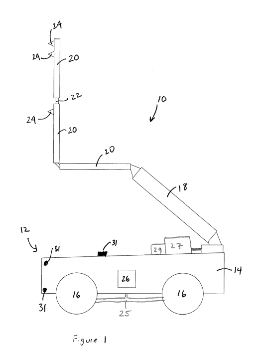
Turning to Figure 1, a schematic diagram of a system for automated de-icing of
an
aircraft is shown. The system 10 includes a mobile platform 12, which itself
includes a platform
14 and a set of wheels 16 mounted to the platform 14 allowing the system 10 to
move from a
starting location to a de-icing location. In a preferred embodiment, the
wheels 16 are able to
swivel or swerve with respect to the platform 14. This may be enabled by a
swerve drive 25.
More importantly, the swerving of the wheels can be performed when the system
or apparatus
10 is in a stationary position.
In the current embodiment, mounted to the platform 14 is a crane arm portion
18. The
crane arm portion 18 is mounted such that it can swivel or move with respect
to the platform 14.
De-icing spray arm portions 20 are mounted to the crane arm portion 18.
Although three
separate de-icing spray arm portions are shown in Figure 1, it will be
understood that the design
of the spray arm portions 20 may be based on the requirements of the system
10. In a preferred
embodiment, the system includes a system drivetrain to control the crane arm
portion and the
de-icing spray arm portions. In a preferred embodiment, the spray arm portions
are electrically
powered by a single battery. In another embodiment, the spray arm portions may
telescope
with respect to each other.
The integration of the spray arm portions 20 with each other and with the
crane arm
portion 18 is preferably via individual joints 22 that allow the spray arm
portions 20 and the crane
arm portion 18 to pivot with respect to each other. In Figure 1, the apparatus
is seen as being
3
CA 03117496 2021-04-23
WO 2020/082180
PCT/CA2019/051506
in one of many operational positions whereby the spray arm portions 20 are
ready to deliver the
de-icing fluid. Alternatively, the spray arm portions may deliver compressed
gas to remove the
contamination or a combination of de-icing fluid and compressed gas. The spray
arms portions
20 further include a set of de-icing nozzles 24 that deliver the de-icing
fluid (and/or compressed
gas) to the aircraft. Each nozzle 24 is able to individually articulate in
both the parallel and
perpendicular axis' relative to the boom or spray arm portion. The apparatus
10 may also
include a de-icing fluid delivery mechanism and storage 27. The mechanism and
storage
include pumps that assist in delivering the de-icing fluid or compressed gas
to the spray arm
portion 20 and the de-icing prays 24). In one embodiment, the pumps are
electric diaphragm
pumps. In the current embodiment, the system further includes a heating
apparatus 29 to heat
the de-icing fluid, however, this may be heated in another location and then
placed into the
storage 27 at a predetermined temperature that is maintained by the storage
27.
The apparatus 10 also includes a processor 26 that controls the apparatus 10.
The
processor 26 may be located, integrated or mounted anywhere within the
apparatus, such as
within or atop the wheeled platform 14 or within the crane arm portion 18. In
the current
embodiment, the processor 26 is located within the platform 14. The processor
26 is preferably
protected from damage via a housing or by different components of the
apparatus 10. The
processor 26 preferably includes a communication module that allows it to
communicate with
external parties using a wireless communication protocol. The processor may
also process
messages or instructions that are received from the external party. The
processor may also
transmit information such as, but not limited to, apparatus state and current
operational
progress, reporting faults, incomplete operations, or uncompletable jobs. The
system may also
be able to determine the level of remaining fluid to determine when its
reservoirs may need to
be re-filled. The processor may also receive movement instructions, such as a
path of motion
or may receive control instructions from a joystick controlled by a remote
user.
The apparatus may further include a set of sensors 31 that assist in
determining safe
operating conditions which may include wind speed, temperature and other
environmental
conditions. The set of sensors and cameras may further determine contamination
levels.
Use of a swerve platform, whereby the wheels 16 can, for example, turn 90
degrees
when in a stationary position, is novel to the de-icing industry and provides
advantages that
were not previously recognized. Also, by enabling the apparatus to move
autonomously (or at
least without a driver), the de-icing process may be performed without needing
a human being
to be present to manually control the mobile platform 12 and/or the spray arm
portions 20 and
the crane arm portion 18.
4
CA 03117496 2021-04-23
WO 2020/082180
PCT/CA2019/051506
In a further embodiment, the apparatus includes components to communicate with
the
external party to transmit information so that the external party is able to
coordinate a fleet of
mobile de-icing machines to effectively address complex winter operational
requirements. In
one embodiment, each apparatus may include a Visual Indicating Process System
(VIPS) that
includes high intensity LEDs to communicate the operational status and mode of
the mobile de-
icing machine. Different colours indicate when the de-icing machine is safe to
approach for
ground personnel as well as the ability for a remote operator, using a camera
system (described
below), to interpret what a state that the de-icing machine is in which
correlates to the a
predetermined system. In one embodiment, the colours may be used in a
following manner
(although it will be understood that colours can be matched with other
operation states and
events).
LED Colour Operational State
OFF De-icing machine off! powered
down
ROTATING CAUTION AMBER LIGHT Powered / In Operation
LED Colour Event Status
YELLOW Truck Safe
ORANGE Spraying Type I Fluid
GREEN Spraying Type IV Fluid
BLUE Treatment Complete
In a further embodiment, the apparatus may include functionality to self test
in order to
detect if it is operating efficiently and as intended. This self test may
include all systems and
subsystems aboard the mobile platform or apparatus. The built in self test
(BIST) preferably runs
upon startup, periodically throughout operation and when switching between
operational modes
and configurations. The mobile platform is also able to detect errors or
failures as they occur
during operations. The mobile platform will communicate these errors and
alarms to the relevant
external third parties.
Turning to Figure 2, a schematic view of another embodiment of a crane arm
portion 18
and de-icing spray portions 20 in a retracted position is shown. In the
current embodiment, there
are only two spray arm portions 20. As discussed above, the crane arm portion
18 is connected
to one of the de-icing spray arm portions 20 via the pivot joint 22. In the
current embodiment,
the de-icing spray arm portions 20 includes a bottom spray arm portion 28 and
a top spray arm
5
CA 03117496 2021-04-23
WO 2020/082180
PCT/CA2019/051506
portion 30 whereby the two spray arm portions 28 and 30 are connected by pivot
joint 22. The
pivot joints 22 enable the apparatus to move from this retracted position to
one of the operational
positions such as the position schematically shown in Figure 1. The apparatus
may further
include an ice blaster spray 32 that is dedicated to de-icing areas that are
typically harder to de-
ice with the de-icing sprays 24. In the current embodiment, the bottom spray
arm portion 28
may be seen as an ice blade de-icing portion while the top spray arm portion
30 may be seen
as an ice hammer de-icing portion which is used for the fuselage of the
aircraft. The ice blade
de-icing portion may be used to scrape excess ice off the fuselage of the
aircraft while the ice
hammer de-icing portion may be used to break off larger ice build-up on the
fuselage of the
aircraft.
Turning to Figure 3a, a schematic front view of a system for automated de-
icing of an
aircraft is shown. In the current embodiment, the system includes a pair of
apparatus 10 for
performing the automated de-icing of an aircraft 50 whereby each of the
apparatus 10 de-ice
one side of an aircraft 50.
In operation, each of the apparatus 10 preferably receive instructions from an
external
party or a remote controller such as a joystick controlled by de-icing
personnel. These
instructions may include a location (or the de-icing location) of the aircraft
to be de-iced within
an airport (such as global positioning system (GPS) co-ordinates), the type of
aircraft being de-
iced and the type of de-icing required. The type of de-icing required may
include locations on
the aircraft that require de-icing or the type of de-icing liquid or liquids
required for de-icing of
the aircraft or both. Other de-icing information may also be transmitted as
will be understood by
one skilled in the art.
It is assumed that each of the apparatus 10 may be located anywhere in the
airport (the
starting location), such as in a different hanger or a different de-icing
facility but that this starting
location is known by the external party. Alternatively, each apparatus 10 may
be located in the
same de-icing facility but may be located within another aircraft bay. By
having mobile de-icing
apparatus 10, less equipment may be required since one mobile de-icing machine
may be able
to service multiple aircraft bays as compared to some current systems where
each aircraft de-
icing bay has its own, static, de-icing equipment and is generally operated by
on-site de-icing
personnel.
After receiving the instructions, the apparatus 10 travel through the airport
from the
starting location to the de-icing location or the location of the aircraft
that it has been instructed
to de-ice. During travel, the crane arm portion 18 and the spray arm portions
20 are preferably
to be in the retracted position. After reaching the de-icing location, the
crane arm portion 18 and
6
CA 03117496 2021-04-23
WO 2020/082180
PCT/CA2019/051506
the spray arm portions 20 move from the retracted position to an operational
position such as
schematically shown in Figure 3a. Operational positions of the spray arm
portions are preferably
determined by the instructions received from the external party and may change
during the
decontamination removal treatment.
The apparatus 10 may then start the de-icing process based on the instructions
received.
As the instructions preferably include the type of aircraft being serviced,
based on the de-icing
location information and the type of aircraft information, each apparatus 10
travels the
circumference or outline of the aircraft along one side of the aircraft
applying or spraying the de-
icing fluid (and/or compressed gas). In some cases, motion of the mobile
platform may be
continuous and in some cases, the mobile platform may stop so that the
extended de-icing or
contamination removal may be performed. As shown in Figure 3a, the apparatus
are spraying,
or applying de-icing fluid, to each side of the body of the aircraft 50.
As the de-icing fluid is sprayed on to the aircraft 50, the apparatus moves
adjacent the
aircraft such as from the front to the rear of the aircraft. In order to
enable lateral movement of
the apparatus, the wheeled platform preferably includes rotating wheels, such
as enabled by a
swerve drive. While each apparatus moves alongside the aircraft 50, the crane
arm portion 18
and the spray arm portions 20 may also move accordingly based on the
instructions received
as the mobile platform travels the outline of the aircraft.
Turning to Figure 3b, another schematic front view of a system for automated
de-icing
of an aircraft is shown. As can be seen in this figure, the spray arm portions
20 are in another
operational position whereby the fuselage and the tail of the aircraft 50 is
being de-iced. The
position of the spray arm portions 20 is controlled by the processor 26 via
the instructions
supplied to it by the external party. Movement of the spray arm portions 20
and the crane arm
portion 18 are preferably controlled by the processor 26. In a preferred
embodiment, movement
of the mobile platform 14 and swerve drive 25 is also controlled by the
processor 26. Although
not shown, it would be understood that different safety measures may also be
implemented,
such as, but not limited to, Light Detection and Ranging (LI DAR) in order to
reduce the likelihood
of collisions or accidents involving the apparatus. Other safety measures
associated with self-
driving automobiles are also contemplated.
For some de-icing operations, as they may require the combined efforts of
multiple
mobile de-icing machines to complete the operation, such as schematically
shown in Figures 3a
and 3b, the mobile de-icing machines may be assigned different portions of the
operation either
individually or as a group. The de-icing process may be broken into parts;
such as a mobile de-
icing machine or a group of mobile de-icing machines may be assigned a
particular area of the
7
CA 03117496 2021-04-23
WO 2020/082180
PCT/CA2019/051506
aircraft (e.g. left wing) or a mobile dse-icing machine could be assigned to
apply a specific fluid
type or a de-icing fluid at a specific temperature or a specific
concentration. Each mobile de-
icing machine also be assigned to a "standby" mode, ready to take the place of
another mobile
de-icing machine in a "hot swap" fashion, should the need arise due to fluid
refilling needs or
unexpected maintenance.
Each apparatus 10 preferably has the functionality to communicate with other
apparatus
to share information and reach consensus on environmental and operating
conditions.
Sharing meteorological data (collected both on and off the platform) the
mobile platform has the
ability to determine if the environmental conditions are safe for de-icing
operations. (e.g.
10 windspeed to determine if it is safe to extend the boom).
In a preferred embodiment, the external party has the ability to issue a stop
command,
immediately halting all current operations and entering a "safe mode". In this
safe mode, all
positions of the wheels, booms, sprays and other moving pieces of the
apparatus 10 are
immediately suspended and held. If any portion of the apparatus is moving at
the time a stop
command is issued, it will immediately, within the constraints of predefined
velocities, come to
a stop and hold the position. Also, each apparatus 10 preferably has the
functionality to issue a
stop command should they detect unintended physical contact with the aircraft,
other mobile
platforms, obstacles or itself (e.g. boom hitting body). Other apparatus
working in coordination
with the apparatus that raised the stop command shall also abide to the stop
command until a
third party has corrected the fault or deemed the situation safe for continued
operation.
Turning to Figure 4a, another schematic front view of a system for automated
de-icing
of an aircraft is shown. In the current embodiment, along with the apparatus
10 that are used
to de-ice the aircraft 50, the system may further include a set of cameras
that are used to assist
in monitoring the de-icing process. One set of cameras 52 may be mounted to
poles 54 remote
from the aircraft in locations where they are able to capture perspective
views of the aircraft. As
shown, the cameras 52 are directed at the body of the aircraft to capture
images of the aircraft
body during the de-icing process. In one embodiment, the set of cameras 52 may
be obtaining
thermal images. The images captured by these cameras 52 may be used by an
individual to
confirm that adequate de-icing has been completed by the apparatus 10 or may
be used to issue
further de-icing instructions for areas that require further de-icing or
contamination removal.
The system may include a further set of cameras 56, such as ones mounted to
the
apparatus 10, to obtain images of the aircraft body. These images, such as
schematically shown
in Figure 4a and labelled as lcebot view, may be transmitted to predetermined
personnel. It will
be understood that in some embodiments, only one of the sets of cameras may be
used. Any
8
CA 03117496 2021-04-23
WO 2020/082180
PCT/CA2019/051506
of the images captured by either set of cameras may be transmitted to
predetermined personnel.
The images may be transmitted from the cameras to the pilots or a remote
display for viewing
by the predetermined personnel. Based on these images, the pilots may be given
the go-ahead
to proceed to a runway or the apparatus may be instructed to do some further
de-icing.
As shown in the bottom of Figure 4a, the images may be delivered to the pilot
such that
the pilot may also provide treatment confirmations or that the pilot is
content with the
performance of the de-icing apparatus. Alternatively, the pilot treatment
confirmations may also
be requests from the pilot for de-icing and may form part of the instructions
that are delivered to
the apparatus 10 by the external party. By understanding the locations of each
of the apparatus
under its control, a main control system may be able to provide an overview or
geospatial
management screen so that the location of each of the apparatus may be
monitored.
Figure 4b is another schematic front view of a system for automated de-icing
of an
aircraft whereby the apparatus are de-icing the tail of the aircraft. Figure
4c is a view similar to
Figure 4a with the geospatial view replaced by an operational control
interface. In a preferred
embodiment, control of the apparatus is preferably via a de-icing control
management system,
which may also be seen as the external party.
Turning to Figures 5a and 5b, schematic views of a single apparatus system is
shown.
Figure 5a is a top view of the action of the single apparatus with respect to
a Boeing 777 aircraft.
As shown in Figure 5a, one embodiment of the stages where the single apparatus
may stop in
order to de-ice the aircraft are shown. In this embodiment, the apparatus 10
stops in twenty
stages around the circumference of the aircraft in order to apply or spray the
de-icing fluid based
on the instructions from the external party, however the number of stages and
location of stages
may be different. In one embodiment, the apparatus follows in the directions
of the arrows
although it will be understood that the apparatus may travel in the opposite
direction of the
arrows. Figure 5b shows a top view of the action of the single apparatus
system with respect to
a Boeing 747. Figure Sc provides a similar top view along with screens that
may be displayed
to personnel based on information delivered by the apparatus.
Turning to Figure 6, another schematic diagram of the apparatus is shown.
In an alternative embodiment, the mobile platform supports 60000 lbs, includes
safety
measures such as ground collision avoidance, is able to receive a set of
Latitude and Longitude
measurements and co-ordinates and be able to track straight line vectors
between points while
maintaining platform X, Y attitude such that the platform does not rotate
while traversing a vector
segment, define low and high speeds and be able to be remotely controlled.
9
CA 03117496 2021-04-23
WO 2020/082180
PCT/CA2019/051506
The spray arm portions are preferably able to communicate with the processor
to indicate
possible incursion/collisions to enable corrections in direction of travel of
the platform or
apparatus. The processor preferably includes the functionality to determine
fuel capacity ¨
battery and diesel. The apparatus is preferably able to store type 1 and type
4 fluid tanks. The
apparatus is also preferably able to provide operational power for a
predetermined time frame,
such as eight hours.
Some technical requirements for the spray arm portions may include that its
power
requirement be electric and hydraulic. In the preferred embodiment, the spray
arm portions, or
the crane arm portion, are bolted to the platform although other fastening
methods are
contemplated. The spray arm portions preferably include an articulating arm
that can extend,
retract and/or move vertically. Furthermore, the spray arm portions preferably
include an
articulating hand on the terminus that houses pre- and post-fluid application
analysis sensor
packages, fluid and air application nozzles. The apparatus may further include
sensors that
measure flow rates, temperatures and densities of fluids. In the preferred
embodiment, the fluids
are applied autonomously.
Overall control of the apparatus preferably includes computer system or
modules that
runs the chassis drives and sensors of the wheeled platform; implement
controls for the spray
arm portions; and combine central intelligence for overall command and control
that coordinates
the apparatus.
Although the present disclosure has been illustrated and described herein with
reference
to preferred embodiments and specific examples thereof, it will be readily
apparent to those of
ordinary skill in the art that other embodiments and examples may perform
similar functions
and/or achieve like results. All such equivalent embodiments and examples are
within the spirit
and scope of the present disclosure.
In the preceding description, for purposes of explanation, numerous details
are set forth
in order to provide a thorough understanding of the embodiments. However, it
will be apparent
to one skilled in the art that these specific details may not be required. In
other instances, well-
known structures may be shown in block diagram form in order not to obscure
the
understanding. For example, specific details are not provided as to whether
elements of the
embodiments described herein are implemented as a software routine, hardware
circuit,
firmware, or a combination thereof.
Embodiments of the disclosure or components thereof can be provided as or
represented as a computer program product stored in a machine-readable medium
(also
referred to as a computer-readable medium, a processor-readable medium, or a
computer
CA 03117496 2021-04-23
WO 2020/082180
PCT/CA2019/051506
usable medium having a computer-readable program code embodied therein). The
machine-
readable medium can be any suitable tangible, non-transitory medium, including
magnetic,
optical, or electrical storage medium including a diskette, compact disk read
only memory (CD-
ROM), memory device (volatile or non-volatile), or similar storage mechanism.
The machine-
readable medium can contain various sets of instructions, code sequences,
configuration
information, or other data, which, when executed, cause a processor or
controller to perform
steps in a method according to an embodiment of the disclosure. Those of
ordinary skill in the
art will appreciate that other instructions and operations necessary to
implement the described
implementations can also be stored on the machine-readable medium. The
instructions stored
on the machine-readable medium can be executed by a processor, controller or
other suitable
processing device, and can interface with circuitry to perform the described
tasks.
11