Note: Descriptions are shown in the official language in which they were submitted.
DESCRIPTION
FILTER CLOTH CLEANING METHOD OF FILTER PRESS
Technical Field
[0001]
The present invention relates to a filter cloth
cleaning method of a filter press which is used for treatment
of drinking water sludge and industrial water sludge and a
production process in the chemical industry, the pulp and
paper industry, and the like.
Background Art
[0002]
Patent Literature 1 describes a filter cloth cleaning
mechanism of a filter press which includes: vibration shafts
of a filter cloth arranged at both sides of the filter press
and provided with supply paths for cleaning liquid; and
cleaning nozzles which jet the cleaning liquid from the
vibration shafts toward the filter cloth.
Citation List
Patent Literature
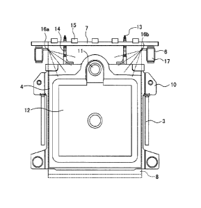
[0003]
Patent Literature 1: JP 2018-69105 A
Summary of Invention
[0004]
In the filter cloth cleaning mechanism of Patent
Literature 1, supply pipes of the cleaning liquid are
integrated with the vibration shafts of the filter cloth and
thus the number of components can be decreased. However,
1
Date Recue/Date Received 2021-04-23
the cleaning nozzles are arranged at only positions upper
right and left of the filter cloth.
[0005]
Cleaning of the filter cloth is performed by jetting
the cleaning liquid from the both sides toward the center of
the filter cloth. In the
cleaning, the cleaning liquid
jetted from the right and left collides with each other at
the center of the filter cloth and then the collided cleaning
liquid flows downward on the filter cloth. Thus, the
cleaning liquid does not reach portions of the filter cloth
in the diagonal directions, which results in uneven cleaning
in the filter cloth.
[0006]
An object of the present invention is to provide a
filter cloth cleaning method of a filter press which can
avoid uneven cleaning.
[0007]
A filter cloth cleaning method of a filter press in
accordance with some embodiments of the present invention is
a method of cleaning a filter cloth of a filter press
including a first cleaning nozzle and a second cleaning
nozzle which jet cleaning liquid from positions upper right
and left of the filter cloth toward respective diagonal
corners of the filter cloth, the method including: jetting
the cleaning liquid from only the first cleaning nozzle; and
jetting the cleaning liquid from only the second cleaning
nozzle.
[0008]
According to the above configuration, it is possible
to efficiently clean the whole surface of the filter cloth
2
Date Recue/Date Received 2021-04-23
of the filter press and thus avoid uneven cleaning. Moreover,
the whole surface of the filter cloth can be evenly cleaned
and thus it is possible to reduce the amount of cleaning
water and the cleaning time, for example.
[0009]
The method may further include jetting the cleaning
liquid simultaneously from both the first cleaning nozzle
and the second cleaning nozzle.
[0010]
According to the above configuration, it is possible
to concentratedly and intensively clean the center of the
filter cloth by the simultaneous cleaning from the right and
left.
[0011]
A liquid supply plate for supplying an original
solution may be fixed to an upper center of the filter cloth.
[0012]
According to the above configuration, it is possible
to easily clean the liquid supply plate and prevent or
resolve clogging of an original solution path. It is also
possible to efficiently clean the filter cloth partially and
thus the amount of cleaning water and the cleaning time can
be reduced.
[0013]
A pair of guide rails may be provided on both sides of
the filter plate on which the filter cloth is stretched and
the filter plate may be supported by the pair of guide rails
via filter plate arms provided on both shoulders of the
filter plate.
[0014]
3
Date Recue/Date Received 2021-04-23
According to the above configuration, the first
cleaning nozzle and the second cleaning nozzle are arranged
to be directed to respective diagonal corners of the filter
cloth and the guide rails are arranged at both sides of the
filter plate. Thus, it is possible to prevent scatter of
the cleaning liquid to the outside of the apparatus.
[0015]
The first cleaning nozzle and the second cleaning
nozzle may be provided on vibration shafts which hang the
filter cloth and supply paths for the cleaning liquid may be
formed in the vibration shafts.
[0016]
According to the above configuration, it is possible
to decrease the number of components.
Brief Description of Drawings
[0017]
Fig. 1 is a side view of a filter press using a filter
cloth cleaning apparatus according to an embodiment of the
present invention.
Fig. 2 is a front view of the main portion of the
filter cloth cleaning apparatus according to the embodiment
of the present invention.
Fig. 3 is a front view of a filter cloth according to
the embodiment of the present invention.
Fig. 4 is a cross-sectional view of the main portions
of filter plates with the filter cloths being hung according
to the embodiment of the present invention.
Fig. 5 is a front view of the filter cloth during a
simultaneous jet cleaning according to the embodiment of the
4
Date Recue/Date Received 2021-04-23
present invention.
Fig. 6 is a front view of the filter cloth during a
one-side jet cleaning according to the embodiment of the
present invention.
Fig. 7 is a front view of the filter cloth during an
other-side jet cleaning according to the embodiment of the
present invention.
Description of Embodiments
[0018]
Description will be hereinbelow provided for
embodiments of the present invention by referring to the
drawings. It should be noted that the same or similar parts
and components throughout the following description of the
drawings will be denoted by the same or similar reference
signs. However, it should be noted that the drawings are
schematic and therefore ratios of dimensions are different
from the actual ones.
[0019]
Accordingly, specific dimensions and the like should
be determined in consideration of the following description.
Moreover, it is a matter of course that portions having
different dimensional relationships and ratios are included
between the drawings.
[0020]
Fig. 1 is a side view of a filter press 1 using a
filter cloth cleaning apparatus according to an embodiment
of the present invention. Fig. 2 is a front view of the
main portion of the filter cloth cleaning apparatus according
to the embodiment of the present invention. Fig. 3 is a
Date Recue/Date Received 2021-04-23
front view of a filter cloth 8 according to the embodiment
of the present invention. Fig. 4 is a cross-sectional view
of the main portions of filter plates 4 with the filter
cloths 8 being hung according to the embodiment of the
present invention. Fig. 5 is a front view of the filter
cloth 8 during a simultaneous jet cleaning according to the
embodiment of the present invention. Fig. 6 is a front view
of the filter cloth 8 during a one-side jet cleaning
according to the embodiment of the present invention. Fig.
7 is a front view of the filter cloth 8 during an other-side
jet cleaning according to the embodiment of the present
invention.
[0021]
As illustrated in Figs. 1 and 2, the filter press 1
includes frames 2 arranged at the right and left, a pair of
guide rails 3 supported between the frames 2, filter plates
4 movably arranged in parallel on the guide rails 3, and an
opening/closing device 5 which opens and closes the filter
plates 4.
[0022]
A pair of vibration shafts 6 are provided above the
filter plates 4 along the guide rails 3. At least one of
the pair of vibration shafts 6 is provided with a vibration
device such as a vibrator 9 and an air spring. A support
bar 7 bridged between the vibration shafts 6 and swingable
up and down is arranged above each filter plate 4. By
hanging the filter cloths 8 on the support bars 7, the filter
cloths 8 are arranged between the filter plates 4. When the
pair of vibration shafts 6 are vibrated by the vibrator 9,
the support bars 7 bridged between the vibration shafts 6
6
Date Recue/Date Received 2021-04-23
are also vibrated and the filter cloths 8 hung on the support
bars 7 are similarly vibrated.
[0023]
Both shoulders of each filter plate 4 are provided with
filter plate arms 10 which are supported between the guide
rails 3 and arrange the filter plates 4 in parallel on the
guide rails 3. An upper center of each filter plate 4 is
formed with an original solution supply path 11.
[0024]
As illustrated in Figs. 2 and 4, center portions of
each filter plate 4 are formed with concave filter beds 12
over which the filter cloths 8 are stretched. A filter
chamber is formed between the parallel-arranged filter
plates 4 by the filter beds 12 and an original solution is
supplied and dewatered between the filter cloths 8 arranged
in the filter chamber.
[0025]
Both shoulders of each filter plate 4 are provided with
upright guide shafts 13 which support the support bar 7.
Springs 14 are inserted around the guide shafts 13
respectively and the support bar 7 is supported by the
springs 14 so as to be elastically swingable. Both side
surfaces of each support bar 7 are provided with latches 15
for hanging the filter cloths 8.
[0026]
Since support bars 7 are bridged between the vibration
shafts 6, the filter cloths 8 hung on the support bars 7 are
vibrated by operating the vibrator 9 provided on the
vibration shaft 6 to separate dewatered cake adhered to the
filter cloths 8 from the filter cloths 8.
7
Date Recue/Date Received 2021-04-23
[0027]
When the vibration shafts 6 are vibrated up and down
by vibration of the vibrator 9 and the dewatered cake is
separated, the support bar 7 bridged between the vibration
shafts 6 is jumped up by the springs 14 inserted around the
guide shafts 13.
[0028]
Cleaning nozzles 16a and 16b are arranged on upper
sides of the vibration shafts 6 respectively. The cleaning
nozzles 16a and 16b are arranged to be directed to the filter
cloths 8 to clean the filter cloths 8 stretched on the filter
plates 4.
[0029]
The cleaning nozzles 16a and 16b are arranged with
their central axes directed in diagonal directions of each
filter cloth 8 respectively and this arrangement enables
cleaning of the whole surface of the filter cloths 8 with a
sufficient cleaning pressure. Moreover, since the cleaning
nozzles 16a and 16b jet the cleaning liquid toward the filter
cloths 8 in the respective diagonal directions of the filter
cloths 8, scattering of the cleaning liquid is prevented by
the guide rails 3 arranged on both sides of each filter plate
4.
[0030]
The inside of each vibration shaft 6 is hollow and
forms a supply path 17 of the cleaning liquid. The cleaning
liquid supplied from the supply paths 17 is jetted from the
cleaning nozzles 16a and 16b provided on the vibration shafts
6.
[0031]
8
Date Recue/Date Received 2021-04-23
The cleaning nozzles 16a and 16b are arranged between
the opened filter plates 4 at every space between the
adjacent filter plates 4 so that all the filter cloths 8 can
be cleaned simultaneously.
[0032]
In the present embodiment, the vibration shafts 6 are
provided with the cleaning nozzles 16a and 16b and the supply
paths 17. However, the present invention is not limited to
the above configuration as long as the cleaning nozzles 16a
and 16b are provided above both sides of each filter cloth
8 and the cleaning liquid can be supplied to the cleaning
nozzles 16a and 16b.
[0033]
Note that in the case where the vibration shafts 6 are
provided with the supply paths 17, one end of each vibration
shaft 6 is connected to the cleaning water storage tank 18
as illustrated in Fig. 1 and cleaning water is supplied to
each vibration shaft 6 by a cleaning water supply pump 19.
[0034]
As illustrated in Fig. 3, an upper edge of each filter
cloth 8 which is rectangular is formed with a bag portion
20. A filter cloth support bar 21 is inserted in the bag
portion 20 and the inserted filter cloth support bar 21 is
locked to the latches 15 of the support bar 7. The bag
portion 20 includes cutout holes 22 which open at positions
where the filter cloth support bar 21 is locked with the
latches 15. An upper
center of each filter cloth 8 is
provided with a through hole 23 which is in contact with the
original solution supply path 11 of the filter plate 4 and
supplies the original solution.
9
Date Recue/Date Received 2021-04-23
[0035]
As illustrated in Fig. 4, the filter cloth support bar
21 inserted into the bag portion 20 at an upper portion of
the filter cloth 8 illustrated in Fig. 3 is exposed from the
cutout holes 22 and then the filter cloth support bar 21
exposed from the cutout holes 22 is locked to the latches 15
of the support bar 7 provided at an upper portion of the
filter plate 4 illustrated in Fig. 2, and thereby hanging
the filter cloth 8. The filter cloths 8 are hung in front
of the filter beds 12 provided on the front and rear of each
filter plate 4.
[0036]
As illustrated in Fig. 4, a liquid supply plate 24 is
tied up (fixed) to one of a pair of the filter cloths 8 hung
between the filter plates 4. The original solution supply
path 11 formed in the filter plate 4 and the through hole 23
in the upper center of the filter cloth 8 are joined to an
original solution path 25 of the liquid supply plate 24, and
a liquid supply path 26 which is branched from the original
solution path 25 of the liquid supply plate 24 and supplies
the original solution to a filter surface of the filter cloth
8 is provided.
[0037]
The filter press 1 first operates the opening/closing
device 5 of the filter plates 4 and moves the filter plates
4 arranged in parallel along the guide rails 3 to one side
to close the filter plates 4. The filter
cloths 8 are
stretched over the filter beds 12 of opposing sides of the
closed filter plates 4 and the filter chamber is formed
between the filter cloths 8 stretched in between the filter
Date Recue/Date Received 2021-04-23
plates 4. The original solution is supplied to the filter
chamber through the original solution supply path 11 and the
original solution is dewatered. Filtrate passing through
the filter cloth 8 is discharged to the outside through an
illustrated discharge port provided in the filter bed 12.
[0038]
After completion of dewatering, the filter plates 4
are opened by the opening/closing device 5 and the dewatered
cake is discharged. The vibrator 9 provided on the vibration
shaft 6 is activated and the support bars 7 bridged between
the vibration shafts 6 are swung. When the dewatered cake
adhered to the filter cloths 8 is separated from the filter
cloths 8, the filter cloths 8 hung on the support bars 7 are
jumped up together with the support bars 7.
[0039]
After the dewatered cake is separated, the cleaning
water is jetted from the cleaning nozzles 16 provided on the
vibration shafts 6. The cleaning water is jetted from the
cleaning nozzles 16 toward the filter cloths 8 to clean the
filter cloths 8.
[0040]
After cleaning of the filter cloths 8 is completed,
the filter plates 4 are closed again to perform dewatering.
[0041]
Hereinafter, a filter cloth cleaning method of a filter
press according to an embodiment will be described in detail.
[0042]
The filter press 1 jets the cleaning liquid from the
cleaning nozzles 16 provided on the pair of vibration shafts
6 to clean the filter cloths 8. Accordingly, the filter
11
Date Recue/Date Received 2021-04-23
cloths 8 are cleaned by jetting the cleaning liquid from the
pair of cleaning nozzles 16a and 16b arranged at positions
upper right and left of the filter cloths 8.
[0043]
The pair of cleaning nozzles 16a and 16b respectively
operate jetting of the cleaning water and the filter cloths
8 are cleaned by performing: a simultaneous jet cleaning
step of jetting the cleaning liquid from both the pair of
cleaning nozzles 16a and 16b; a one-side jet cleaning step
of jetting the cleaning liquid from only the cleaning nozzle
16a which is one of the cleaning nozzles 16a and 16b; and an
other-side jet cleaning step of jetting the cleaning liquid
from only the cleaning nozzle 16b which is the other of the
cleaning nozzles 16a and 16b. By performing these steps,
the portion of the filter cloth 8 in the vicinity of the
liquid supply plate 24 can be concentratedly cleaned and the
whole surface of the filter cloth 8 also can be cleaned.
[0044]
Note that jetting of the pair of cleaning nozzles 16a
and 16b can be switched by a known technique such as ON/OFF
of the cleaning water supply pump 19 and switching of
opening/closing of valves.
[0045]
The simultaneous jet cleaning step will be described
with reference to Fig. 5.
[0046]
Since the liquid supply plate 24 is provided at the
upper center of the filter cloth 8, dirt is concentrated in
the portion of the filter cloth 8 in the vicinity of the
liquid supply plate 24. Therefore,
the simultaneous jet
12
Date Recue/Date Received 2021-04-23
cleaning step is performed first.
[0047]
In the simultaneous jet cleaning step, the cleaning
liquid is simultaneously jetted from the pair of cleaning
nozzles 16a and 16b. In this case, since the cleaning water
is simultaneously jetted from the right and left cleaning
nozzles 16a and 16b, the cleaning water collides with each
other in the center of the filter cloth 8. The collided
water flows downward.
[0048]
At this time, since the pair of cleaning nozzles 16a
and 16b are arranged to be directed to the respective
diagonal corners from positions upper right and left of the
filter cloth 8, the cleaning water does not reach lower right
and left portions of the filter cloth 8.
[0049]
The liquid supply plate 24 is arranged at the upper
center of the filter cloth 8 and the liquid supply plate 24
is cleaned intensively with the force of collision of the
cleaning water.
[0050]
After a prescribed time has elapsed, the simultaneous
jet cleaning step is completed.
[0051]
Next, the one-side jet cleaning step will be described
with reference to Fig. 6.
[0052]
After the simultaneous jet cleaning step is completed,
the step shifts to the one-side jet cleaning step.
[0053]
13
Date Recue/Date Received 2021-04-23
In the one-side jet cleaning step, the cleaning water
is jetted from the cleaning nozzle 16a which is one of the
pair of cleaning nozzles 16a and 16b. Since the cleaning
nozzle 16a is arranged to be directed to the diagonal corner
of the filter cloth 8, the cleaning liquid is jetted to the
diagonal lower portion of the filter cloth 8. In the
simultaneous jet cleaning step, the cleaning liquid does not
reach the diagonal corner of the filter cloth 8 due to
collision of the cleaning liquid from the right and left.
In contrast, in the one-side jet cleaning step, since the
cleaning liquid is jetted from only one cleaning nozzle 16a,
the cleaning liquid reaches the diagonal corner of the filter
cloth 8 and thus an uncleaned portion of the filter cloth 8
(the lower right of the filter cloth 8 in Fig. 6) can be
cleaned up.
[0054]
After a prescribed time has elapsed, the one-side jet
cleaning step is completed.
[0055]
Next, the other-side jet cleaning step will be
described with reference to Fig. 7.
[0056]
After the one-side jet cleaning step is completed, the
step shifts to the other-side jet cleaning step.
[0057]
In the other-side jet cleaning step, the cleaning water
is jetted from the cleaning nozzle 16b which is the other of
the pair of cleaning nozzles 16a and 16b. Since the cleaning
nozzle 16b is arranged to be directed to the diagonal corner
of the filter cloth 8, the cleaning liquid is jetted to the
14
Date Recue/Date Received 2021-04-23
diagonal lower portion of the filter cloth 8. In the
simultaneous jet cleaning step and the one-side jet cleaning
step, the cleaning liquid does not reach the diagonal corner
of the other cleaning nozzle 16b. In contrast, in the other-
side jet cleaning step, since the cleaning liquid is jetted
from only the other cleaning nozzle 16b, the cleaning liquid
reaches the diagonal corner of the filter cloth 8 and thus
an uncleaned portion of the filter cloth 8 (the lower left
of the filter cloth 8 in Fig. 7) can be cleaned up.
[0058]
After a prescribed time has elapsed, the other-side
jet cleaning step is completed.
[0059]
The simultaneous jet cleaning step, the one-side jet
cleaning step, and the other-side jet cleaning step can be
performed in any order and the portion of the filter cloth
8 in the vicinity of the liquid supply plate 24 can be
concentratedly cleaned and the whole area of the filter cloth
8 can be cleaned.
[0060]
Note that the simultaneous jet cleaning step may be
omitted depending on the state of dirt of the filter cloth
8 (the portion in the vicinity of the liquid supply plate
24, for example). In the state, the whole surface of the
filter cloth 8 can be cleaned by the one-side jet cleaning
step and the other-side jet cleaning step.
[0061]
The filter cloth cleaning method of the filter press
according to the embodiment is applicable to a filter press
in which a pair of cleaning nozzles are provided above a
Date Recue/Date Received 2021-04-23
filter cloth and the cleaning nozzles are directed in the
respective diagonal directions of the filter cloth. Since
the whole surface of the filter cloth is efficiently cleaned,
the amount of cleaning water and the cleaning time can be
reduced. The filter press can be used not only for drinking
water sludge and industrial water sludge, but also for a
production process in a chemical plant and the like.
[0062]
In this way, the present invention includes various
embodiments not described above. Therefore, the scope of
the present invention is determined only by the invention
identification matters according to claims reasonable from
the foregoing description.
16
Date Recue/Date Received 2022-03-29