Note: Descriptions are shown in the official language in which they were submitted.
PNEUMATICALLY COUPLED FLUID CONTROL SYSTEM AND PROCESS
WITH AIR DETECTION AND ELIMINATION
CROSS-REFERENCE TO RELATED APPLICATIONS
This application claims the benefit of U.S. Provisional Patent Application No.
61/826,863, filed May 23, 2013.
BACKGROUND
Fluid flow control is an essential part of medical devices such as intravenous
infusion pumps and enteral feeding systems. These fluid flow control systems
must meet
a complex and conflicting set of requirements, such as broad flow rate range,
wide
ranging fluid viscosity, inevitable presence of harmful amounts of gas,
changing source
pressure, changing patient pressure, variable patient line resistance, and a
wide range of tubing
configurations.
Reliability and ability to detect fault conditions are critical features of
such
flow control devices. Low acquisition and maintenance costs are important
characteristics also.
The usability of the system is vitally important, as it impacts the workflow
of
caregivers, which has a strong, but indirect, impact on the quality of patient
care. This
usability includes ease of loading the sterile tubing set, the need for
attention from the
caregiver during the fluid delivery period, and attending to unnecessary alarm
conditions.
Conventional fluid control or pumping mechanisms suffer from an unfavorable
tradeoff between sophistication and complexity. The added complexity of many
modern
systems has led to a lack of reliability, resulting in product performance
failures, high levels
of maintenance, product recalls by regulatory agencies, and documented high
rates of patient
harm.
One of the earlier types of fluid pump, as marketed by Harvard Apparatus
Company and
as replicated in the market hundreds of times thereafter, is a syringe pump.
In a syringe pump,
fluid is contained within a commonly found glass or plastic syringe,
manufactured with a well-
specified diameter and stroke length. These are the
Date Recue/Date Received 2021-07-06
WO 2014/190191
PCT/US2014/039211
same syringes that are used to provide manual injections of sterile fluid. The
piston of
the syringe is securely held and, usually with a lead screw mechanism, the
piston is
advanced in carefully timed steps of a motor. Each step of the motor expresses
a
known amount of liquid out of the syringe and into a line going to the
vasculature of
the patient. The syringe pump offers a very simple mechanism and an
extraordinarily
simple control system, consisting of a timer circuit, set by the desired fluid
flow rate.
Force and position sensors are often added to provide feedback regarding
occlusions,
misloading, and end of infusion. The syringe pump design is inherently
limited,
however, by the relatively small size of the syringe, in the amount of fluid
infused and
in the maximum fluid flow rate, so this design does not satisfy the needs of
many
clinical applications. Ironically, at the very small volumes and flow rates,
the syringe
pump suffers from a discontinuity of fluid flow, based on the high static
friction of the
syringe. Very small movements of the drive motor do not necessarily translate
into
movement of the piston and delivery of fluid; it may take multiple motor steps
and
multiple time intervals before the piston actually delivers fluid to the
patient. Long
delay periods between delivery are not desirable clinically. A further
deficiency in the
syringe pump is the improper impedance match with the patient's vasculature;
the
syringe pump motor drive is equipped with a motor that is capable of reliably
meeting
the maximum torque foreseen by the system. This powerful motor is also geared
down such that very low displacements can be achieved, giving the pump the
ability
to deliver at low flow rates. The combination of the powerful motor and the
gearing,
however, allows the syringe drive to generate fluid pressures that are far in
excess of
those needed to safely infuse a fluid into the vasculature of a patient. The
consequence of this potentially high pressure output is that harmful levels of
fluid
pressure can be applied to the patient, with deleterious effects, especially
in the event
of an extravasation of the infusion catheter or the creation of a bolus upon
release of a
temporary occlusion.
Variations of the syringe pump are to be found in the form of a reciprocating
piston that can draw from a fluid bag or vented bottle. Such devices, as found
with the
Abbott/Hospira PlumTM infusion device, overcome the volume limitation of a
syringe
pump. Added complexity for valving serves to increase cost and reduce
reliability. A
large volume pump, because of its multiple fluid connections and air spaces,
creates
an environment, not found with syringe pumps, for the introduction of harmful
air
bubbles, which must be detected and accommodated. These reciprocating piston
2
Date Recue/Date Received 2021-05-07
WO 2014/190191
PCT/US2014/039211
pumps still retain the disadvantage of impedance mismatch described above for
syringe pumps.
The most common form of infusion pump is the peristaltic pump, whereupon
fingers or rollers occlude a section of flexible tubing in peristaltic
fashion, expressing
fluid out the tube toward the patient. This mechanism provides the simplest
configuration to carry the sterile fluid in the form a simple flexible tube.
The
peristaltic pump suffers the same impedance mismatch fate as the syringe pump,
because the forces required to faithfully occlude a portion of the flexible
tube are
great, allowing the pump to generate harmfully high infusion pressures. This
.. potentially high pressure can be mitigated through the use of force sensors
on the
tubing, adding complexity and cost. The problem with air ingress to the
patient is the
same as with the reciprocating piston pump described above. The peristaltic
pump
introduced a new problem related to fluid flow accuracy, since the amount of
fluid
expressed to the patient is entirely dependent on the interior diameter of the
fluid
tubing in its uncompressed state. In fact the surface area error is a square
law function
of the error in the diameter, so a 10% error in the diameter would yield an
unacceptable 21% (1.12) error in the volume expressed to the patient.
Unfortunately,
there are two very common events that can reduce the effective diameter of the
tubing: one is the fatigue of the tubing as it is repeatedly worked by the
peristaltic
mechanism and the other is the failure of the tubing to refill completely due
to low
flow from the fluid source.
There is another class of pumps providing single flow rates using a constant
force spring, membrane, or gas reaction pushing fluid against a fixed,
calibrated
resistance. These devices do not provide the programmable variation of flow
rate
needed for most clinical applications.
One variation of the reciprocal piston pump was designed and marketed by
FluidSense Corporation of Newburyport, MA. It used a flexible membrane
connected
to a spring-loaded piston on one side and sterile fluid on the other. A low
cracking
pressure passive inlet valve and an actively operated momentary outlet valve
provided
for a pumping action if the spring loaded piston were "cocked" back to load
the
spring, providing a positive fluid force. A highly sensitive linear encoder
was used to
watch the position of the spring-loaded piston, providing information on the
fluid
pressure and volume. This design allowed for a simplified and more sensitive
pump
mechanism, but the flow was intermittent with the action of each pulse of the
outlet
3
Date Recue/Date Received 2021-05-07
WO 2014/190191
PCT/US2014/039211
valve and the driving pressure varied from 3 to 7 PSIg, higher than necessary
for most
clinical applications. It also suffered from the introduction of air bubbles,
as with all
large volume pumping systems.
Programmable infusion devices, as opposed to single rate delivery systems, all
suffer from two effects of electromechanical complexity. First, there are
usually tight
mechanical tolerances which can be disturbed by shock, vibration, temperature
shifts,
and aging. Infusion pumps arc often out of their performance specifications,
sometimes intermittently, making troubleshooting very expensive and difficult.
Secondly, these complex mechanisms are often difficult to disinfect. Customers
have
only recently become sensitized to the extremely high importance of
disinfecting
infusion pumps and other medical devices. Cross contamination of patients is
one of
the top healthcare issues in the acute care environment.
Another particular problem that patients and caregivers face with great
regularly is the presence of air bubbles in the fluid path. Conventional
infusion pumps
observe a segment of tubing via an ultrasonic or optical detector circuit.
They reliably
detect bubbles with high sensitivity. Unfortunately, the specificity of these
sensors is
low, so false alarms are commonplace. When these bubbles are detected, three
bad
things happen. First, the pump goes into an alarm condition and fluid flow to
the
patient is halted, which can often cause harm to the patient by withholding
needed
medication. Second, the alarm at the bedside causes significant distress to
the patient
and the patient's family. Third, the alarm disrupts the nurse's workflow,
taking time
away from other patients and directing the nurse's attention toward the
infusion pump
and away from the patient.
Air eliminating filters are commonly found in infusion therapy administration
sets. These filters fail to solve the problems identified above, because these
filters do
not function properly when exposed to negative gauge pressures if they are
positioned
proximal to the infusion pump. If these filters are placed below the infusion
pump,
then there is no way for the pump to verify that these filters are in place,
so the alarms
must still stay active. These filters must also incorporate hydrophilic
filters, which are
not compatible with certain medical fluids, such as whole blood.
SUMMARY OF THE INVENTION
The present invention relates to a fluid control system implemented as a
pneumatically coupled direct drive. The system is reliable, tolerant of
changing
4
Date Recue/Date Received 2021-05-07
WO 2014/190191
PCT/US2014/039211
conditions, and sensitive to conditions that prevent the accurate delivery of
fluid. The
system provides a simple actuating mechanism coupled with a low-pressure,
closed
loop control system, which overcomes the limitations of prior art systems
described
above.
The pneumatic drive of the fluid control system incorporates a linear actuator
that interfaces with a gas reservoir to effect known volume changes in the gas
reservoir. In one embodiment, the linear actuator comprises a drive motor
coupled to
a mechanism that provides linear motion to push or pull a reciprocating
element, such
as a bellows or a piston, by known linear increments. The reciprocating
element
translates bi-directionally in one dimension and has a fixed, known cross-
sectional
area, for example, in a plane orthogonal to the direction of translation.
Thus,
translation by a known distance results in a known volume change within the
gas
reservoir. The reciprocating element interfaces with a gas, typically air, in
the gas
reservoir such that translation of the reciprocating element increases or
decreases the
gas volume in the gas reservoir. The motor can be moved in either direction to
increase or decrease the gas volume. A pressure sensor in the gas reservoir
senses the
gas pressure therein. A vent valve to ambient is also provided in the gas
reservoir.
The gas reservoir is in fluid communication with a divided fluid chamber. The
fluid chamber is separated by a flexible membrane into a gas-side reservoir
and a
fluid-side reservoir. The gas in the gas-side reservoir is in fluid
communication with
the gas in the gas reservoir of the linear actuator. The fluid-side reservoir
is filled
primarily with a liquid, such as medication or a feeding solution for delivery
to the
vasculature of a patient. Reciprocal motion of the reciprocating element,
e.g., the
piston or bellows, under control of the drive motor, imposes positive or
negative
volume differences on the gas in the gas-side reservoir, which results in a
decrease or
an increase in the pressure of the gas. This in turn causes a flexing of the
membrane,
which communicates the pressure difference to any fluid in the fluid-side
reservoir.
Passive inlet and outlet check valves are disposed along the fluid flow path
through
the fluid-side reservoir. The inlet and outlet check valves open in response
to the
pressure changes in the fluid to create a unidirectional pumping action to
move the
fluid in through the inlet check valve and subsequently out through the outlet
check
valve.
The system includes a controller that operates the pneumatic drive. The
controller is operable to control delivery of liquid to the fluid sink by
determining a
5
Date Recue/Date Received 2021-05-07
WO 2014/190191
PCT/US2014/039211
volume of liquid to be delivered as the difference between a target volume of
liquid to
be delivered and a volume of liquid already delivered and operating the
pneumatic
drive in increments calculated to deliver the volume of liquid to be
delivered. The
controller is operable to calculate the volume of liquid to be delivered at
successive
time intervals and update the volume of liquid already delivered after each
calculation
of the volume of liquid already delivered.
The controller receives sensed pressure data from the pressure sensor at
regular time intervals, including before and after a controlled movement of
the
pneumatic drive, and compares the pressure data to a known change in gas
volume
resulting from said controlled movement. The controller calculates a volume of
gas
based on the pressure data and the known change in gas volume based on an
ideal gas
law relationship between the sensed pressure data and the known gas volume.
The controller is also operable to determine pressure trends indicative of
various conditions, such as an impedance or a resistance in the fluid flow
path from
the fluid source or to the fluid sink. The impedance or the resistance in the
fluid
source can be indicative of, for example, an occlusion in a line on the fluid
flow path,
an amount of liquid remaining in the fluid source, a viscous liquid at the
fluid source,
or the presence of a syringe. The impedance or the resistance in the fluid
flow path to
the fluid sink can be indicative of, for example, an occlusion in a line on
the fluid
flow path or a disconnected connection to the fluid sink.
In another aspect, the fluid control system incorporates an air detection and
active air elimination mechanism that has improved detection specificity and
is
operable to eliminate an unlimited amount of air so as to avoid the negative
aspects of
air bubbles. The air elimination mechanism includes a hydrophobic filter
material that
prevents passage of liquid and a one way valve through which air can leave the
system.
DESCRIPTION OF THE DRAWINGS
The invention will be more fully understood form the following detailed
description taken in conjunction with the accompanying drawings in which:
Fig. 1 is a schematic block diagram of one embodiment of a fluid control
system;
Fig. 2 is a schematic block diagram of a controller for use in the fluid
control
system of Fig. 1;
6
Date Recue/Date Received 2021-05-07
WO 2014/190191
PCT/US2014/039211
Fig. 3 is a schematic diagram illustrating positions of a linear actuator of
the
fluid control system at various states in a pumping cycle;
Fig. 4a is a schematic diagram of a pumping chamber of Fig. 1 including an
air elimination system;
Fig. 4b is an expanded schematic diagram of the air elimination system of Fig.
4a;
Fig. 5a is an isometric view of one embodiment of a fluid administration set
illustrating a cassette and a housing;
Fig. 5b is an isometric view of Fig. 5a illustrating the cassette inserted
within
the housing;
Fig. 6 is an exploded view of the cassette of Fig. 5a;
Fig. 7a is a cross-sectional view of the cassette;
Fig. 7b is a further cross-sectional view of the cassette;
Fig. 8 is a cross-sectional view of an inlet valve in the cassette;
Fig. 9 is a cross-sectional view of an air valve in the cassette;
Figs. 10a and 10b are isometric views illustrating an air filter for an air
elimination system used with the cassette;
Fig. 1 la is an isometric view of a by-pass valve assembly used with the
cassette;
Fig. 1 lb is an isometric view of the by-pass valve assembly in a closed
position;
Fig. 12a is an exploded view of the cassette illustrating a pneumatic pathway
within the cassette;
Fig. 12b is a top view of the cassette body illustrate the pneumatic pathway;
Fig. 13 is a schematic block diagram of an embodiment of a failsafe circuit
incorporating an additional vent valve;
Fig. 14 is a graph of a pressure response to a known decrease in gas volume;
Fig. 15 is a graph of a pressure response to a known increase in gas volume;
Fig. 16 depicts the change in pressure when a pressure-activated one way
valve is opened with increasing pressure;
Fig. 17 is a schematic graph of volume vs. time to illustrate flow
calculations
made during fluid delivery;
Fig. 18 depicts the change in pressure when the sink pressure changes;
Fig. 19 depicts the change in pressure when the sink impedance changes;
7
Date Recue/Date Received 2021-05-07
WO 2014/190191
PCT/US2014/039211
Fig. 20 depicts the differentiation between pressure and impedance changes in
the sink;
Fig. 21 depicts pressure responses over time during various conditions during
a fill cycle;
Fig. 22 depicts pressure responses over time during various conditions during
a delivery cycle; and
Fig. 23 depicts a pressure response over time during a portion of a fluid
delivery stroke.
DETAILED DESCRIPTION OF THE INVENTION
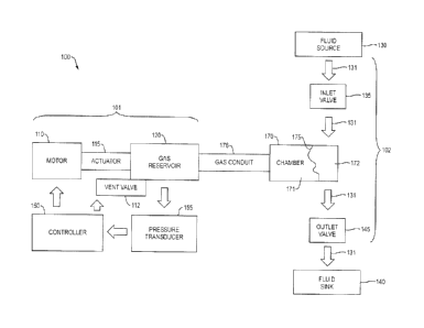
Fig. 1 depicts a schematic block diagram for one embodiment of a fluid
control system 100. The system incorporates a pneumatic drive 101 that
interfaces
with a fluid administration set 102 by which controlled amounts of fluid are
withdrawn from a fluid source 130 and delivered to a fluid sink 140, such as
the
vasculature of a patient. The fluid control system can be embodied as a stand-
alone
pumping system or as a subassembly that is coupled to another pumping system
that
includes other components, such as a user interface, drug safety software,
power
supply, chassis, etc.
The fluid source 130 may be, e.g., a fluid contained within a flexible bag, a
vented bottle, or a liquid filled syringe. The fluid flows on a flow path 131
through a
pumping chamber 170, which is a rigid body or housing having a fixed volume.
The
chamber is divided by a flexible membrane 175 that is impermeable to gas or
liquid
into a gas-side chamber 171 and a fluid-side chamber 172. The flexible
membrane
175 is sealingly fastened about its periphery within the chamber 170, but is
otherwise
free to move without restriction. Gas pressure within the gas-side chamber 171
imposes the same pressure within the fluid-side chamber 172. There is
effectively no
pressure differential across the flexible membrane 175. Pressure changes in
the gas-
side chamber are directly communicated to the fluid-side chamber via the
flexible
membrane and vice versa.
The fluid-side chamber 172 is disposed on the fluid flow path 131 and is in
fluid communication with the fluid source 130 via an inlet valve 135. The
fluid side
chamber 172 is also in fluid communication with the fluid sink 140 via an
outlet valve
145. The inlet valve and outlet valve each are passively operated one-way
check
valves and only open when the pressure differential between the upstream fluid
and
8
Date Recue/Date Received 2021-05-07
WO 2014/190191
PCT/US2014/039211
downstream fluid reaches a predetermined cracking pressure. The inlet valve
135 and
outlet valve 145 each are normally closed to flow and require a relatively
high
differential pressure to open them in a forward direction. No practical amount
of
differential pressure can open them in the reverse direction. In one
embodiment,
suitable as a medical infusion pump, both valves 135, 145 are selected to have
a
relatively high cracking pressure, on the order of 1 PSId. The particular
cracking
pressure depends on the application, as would be appreciated by one of skill
in the art.
The system also includes a pneumatic drive that is coupled to the gas-side
chamber 171 to effect known incremental positive or negative volume changes
that in
turn cause positive or negative pressure changes in the gas-side chamber that
are
communicated to the fluid-side chamber 172. In one embodiment, the pneumatic
drive includes a linear actuator, for example, a drive motor 110, such as a
stepper
motor or encoded DC motor or another electromechanical element that produces
accurate incremental bi-directional movements. The drive motor is coupled to a
cam
or a lead screw mechanism or other mechanism that outputs linear motion.
However,
any linear actuator mechanism could be used, so long as its position is known
and it
has negligible hysteresis or backlash. The drive motor 110 is coupled to a
reciprocating element 115 that reciprocates within a gas reservoir 120. The
reciprocating element 115, e.g., a bellows or piston, translates bi-
directionally in one
dimension. Thus, translation by a known distance results in a known volume
change.
The reciprocating element interfaces with a gas, typically air, in the gas
reservoir 120
such that translation of the reciprocating element increases or decreases the
gas
volume in the gas reservoir by a known amount. The reciprocating element 115
and
gas reservoir 120 together form a syringe-like mechanism.
The gas reservoir 120 is in fluid communication with the gas-side chamber
171. A gas conduit 178 may be provided to fluidly connect the gas reservoir
120 with
the gas-side chamber 171, depending on the configuration of the overall
pumping
system. A vent valve 112 is provided that can be opened to vent air in the gas
reservoir to ambient. Momentarily opening the vent valve equilibrates the
pressure in
the reservoir 120 and connected space (gas conduit 178 and gas-side chamber
171) to
atmospheric pressure. Any suitable vent valve can be used, such as an
electromechanical solenoid valve. A pressure sensor 155, such as any suitable
pressure transducer, is also provided to measure the pressure within the gas
reservoir
9
Date Recue/Date Received 2021-05-07
WO 2014/190191
PCT/US2014/039211
120, which also provides a measure of the pressure in the gas-side chamber and
the
fluid-side chamber of the pumping chamber.
A system controller 150 is provided in operative communication with the
motor 110 and the vent valve 112 and with the pressure sensor 155 to receive
pressure
data. The controller 150 includes a processor or microprocessor or the like
and
support electronics for communication, sensing, computation, and actuator
control.
The controller 150 includes non-volatile memory (e.g., ROM) for storage of
data and
instructions, volatile memory (e.g., RAM) for input and output, a clock, and
an
input/output (I/O) control unit. The controller 150 can be provided as a
microcontroller unit on a single chip. The controller can also interface with
another
computer or controller that is part of an overall pumping system or pumping
application, discussed further below.
The drive motor 110 is moved in known increments based on commands from
the controller 150, which in turn moves the reciprocating element 115 a known
length
to achieve a known change in gas volume in gas reservoir 120. The volume
change, in
turn, results in a change in pressure in reservoir 120. The gas pressure seen
at
reservoir 120 and gas conduit 178 is equilibrated with the gas pressure within
the gas-
side chamber 171 and imposes the same pressure within the fluid-side chamber
172
by flexing of the flexible membrane 175, as there is no differential pressure
across the
membrane.
In one embodiment, the reciprocating element 115 of the linear actuator is
formed as a bellows capable of controllable linear translation in one
dimension. One
end of the bellows is sealingly fixed to a rigid housing forming the gas
reservoir 120
via, for example, a flange, and the other end of the bellows is coupled to the
motor
110 for linear movement, via, for example, a flange or an end plate. Thus, the
diameter or cross-sectional area of the bellows is effectively fixed and
therefore
known. The interior of the bellows is open to and forms part of the gas
reservoir.
Accordingly, when the bellows translates linearly, generally in a direction
orthogonal
to the plane of the end plate of known diameter, the volume change can be
determined
from the length of translation multiplied by the cross-sectional area of the
bellows.
The length of translation is known, because it is determined by the
incremental
motion of the drive motor, which is controlled by the controller 150.
Implementation of the reciprocating element as a bellows is advantageous,
because the bellows is capable of linear translation without stiction or
friction against
Date Recue/Date Received 2021-05-07
WO 2014/190191
PCT/US2014/039211
a housing. The bellows can be designed and fabricated with a known stroke
length
and spring rate and operating pressure range on both sides of the bellows. Any
suitable material, such as stainless steel or another metal alloy, for
example, a
titanium alloy, can be used in forming the corrugations of the bellows.
Suitable
bellows are commercially available from, for example, BellowsTech, LLC, of
Florida.
In another embodiment, the reciprocating element of the linear actuator is
formed as a piston. The piston is coupled to the motor for linear translation
within a
cylinder that is coupled to or a part of the gas reservoir 120. The diameter
or cross-
sectional area of the piston end face (or cylinder) is fixed and known. Thus,
as with
the bellows, when the piston translates linearly, the volume change can be
determined
from the length of translation multiplied by the known, fixed cross-sectional
area of
the piston end face. The length of translation is known, because it is
determined by
the incremental motion of the drive motor, which is controlled by the
controller 150.
The linear actuator can also refer to an array of pistons, connected to a
single drive
motor. Various linear or rotary configurations of pistons can be used, for
example, to
meet packaging requirements.
The controller 150 can adjust pressure in three ways. To create increasing
gauge pressure within the gas reservoir 120 by the linear actuator 115, which
is then
communicated to the gas-side chamber 171 and then to the fluid-side chamber
172,
the controller 150 can move motor 110 in one direction, for example,
clockwise. To
create decreasing gauge pressure within the gas reservoir 120 by the linear
actuator
115, which is then communicated to the gas-side chamber 171 and then to the
fluid-
side chamber 172, controller 150 can move motor 110 in the opposite direction,
counterclockwise. To produce zero gauge pressure within the gas reservoir 120,
which is then communicated to the gas-side chamber 171 and then to the fluid
side
reservoir 172, the controller 150 can activate the vent valve 112.
By way of an overview, in operation to perform a FILL step, the vent valve
112 is closed and the linear actuator 115 is retracted, which increases the
volume and
decreases the pressure in the gas reservoir 120 and gas-side chamber 171. The
pressure in the fluid-side chamber 172 is similarly decreased, which leads to
a
pressure differential across the inlet valve 135. When the pressure
differential reaches
the cracking pressure of the inlet valve, the valve opens and fluid, primarily
liquid,
from the fluid source flows through the inlet valve into the fluid-side
chamber, in a
FILL step. To perform a DELIVER step, the vent valve is closed and the linear
11
Date Recue/Date Received 2021-05-07
WO 2014/190191
PCT/US2014/039211
actuator is advanced. The pressure in the gas-side chamber and the fluid-side
chamber
increases, which leads to a pressure differential across the outlet valve 145.
When the
pressure differential reaches the cracking pressure of the outlet valve, the
valve opens
and liquid from the fluid-side chamber flows through the outlet valve to the
fluid sink,
in an DELIVER step.
Referring now to FIG. 2, the controller 150 uses minimal inputs and outputs to
achieve flow control for the system. A point along the travel of the linear
actuator
115, a "home" or "park" position, is stored in storage 321. Maximum and
minimum
travel positions of the linear actuator during FILL and DELIVER steps are
stored as
well. Periodic measurements are made by the pressure sensor 155 and
transmitted as a
pressure signal 322 to the controller 150. Motor control signals 324 are
transmitted to
the motor drive 110 to move in either direction and over a wide range of
speeds. The
vent valve 112 is normally closed and can be opened programmatically via vent
control signals 325. The controller also includes a clock 326 for timing.
Commands from another controller or a host processor 380 from, for example,
an overall pumping system, can be exchanged digitally, for example, via serial
communication link 323. Only a small number of supported commands and queries
are needed. The communication link can use a common protocol such as Wi-Fi
(IEEE
802 wireless standards), I2C, SPI, ZigBee, USB, TCP/IP, BTLE, or other
protocols.
The use of a high level, simple communications system allows for simplified
software
architecture and a more reliable verification process. The other controller
380 can
reside on a mobile device, such as an iPhone, or a tablet device, such as an
iPad,
which contains a program or application (app) for receiving data from and
transmitting instructions to the system controller 150.
Fig. 3 shows various states and the association with positions of the linear
actuator 115. The linear actuator 115 can be moved by the motor 110 under
control of
the controller 150 to any position. Certain positions along the entire stroke
are
described as follows. The positions PARK 811 (the "home" position), MAX (or
MAX
PISTON) 812 (the position at which the linear actuator is fully retracted
during a
pumping cycle), and MIN 815 (or MIN PISTON) (the position at which the linear
actuator is least retracted (or fully advanced) during a pumping cycle) are
fixed
positions by design. The position POS CRACKING 813 (when the outlet valve
opens) and position NEG CRACKING 814 (when the inlet valve opens) are
variable,
depending upon the conditions of the infusion. The controller 150 includes
12
Date Recue/Date Received 2021-05-07
WO 2014/190191
PCT/US2014/039211
instructions that maintain the system in one of several states, which
determine the
movement of the linear actuator 115 and the interpretation of the pressure
signal 322.
When idle, the system is in the state UNLOCK 821 and the linear actuator is
brought
to the position PARK 811. Upon instruction to begin an infusion (which may be
transmitted by the host processor 380), the controller 150 enters the state TO
MIN
822 and the linear actuator 115 is brought to the position MIN 815 with the
vent valve
112 open. Once the infusion begins, the controller 150 enters the state CHANGE
NEG 823 and with the vent valve closed, the linear actuator 115 is gradually
moved
(retracted) until the inlet valve 135 opens at the position NEG CRACKING 814.
The
state FILL 824 begins, during which the fluid-side reservoir 172 fills with
liquid from
the source, and continues until the fluid-side reservoir 172 reaches its
maximally
filled position. In preparation to deliver fluid to the fluid sink 140, the
controller 150
moves the linear actuator 115 to the position MAX 812 with the vent valve 112
open
in the state TO MAX 825. The controller 150 enters the state CHANGE POS 826
and
with the vent valve closed, the linear actuator 115 is gradually moved
(advanced) until
the outlet valve 145 opens at position POS CRACKING 813. Finally, the linear
actuator 115 advances at a speed to deliver the proper amount of fluid in the
state
DELIVER 827. When the state DELIVER 827 is complete, the controller 150
reverts
back to the state TO MIN 822, continuing the cycle until the set target is
complete.
The reservoir 120 with connected dead space of the gas conduit 178 and the
pumping chamber 175 has a finite volume. The linear actuator 115 has a finite
length
of travel and can reach the limits of its position in either direction. If the
controller
150 seeks an increase in pressure when the linear actuator 115 is at position
MIN 815,
then it must move the linear actuator towards position MAX 812 while the vent
valve
112 is open. The use of the vent valve allows movement of the linear actuator
without
the generation of any pressure changes. Once the position MAX 812 is reached,
then
the vent valve 112 is closed and the linear actuator is moved towards the
position
MIN 815, reducing the effective volume of the reservoir 120 and increasing the
pressure of the gas-side chamber 171. Similarly, if the controller 150 seeks a
decrease
in pressure when the linear actuator 115 is at the position MAX 812, then it
must
move the linear actuator towards position MIN 815 while the vent valve 112 is
open.
Once the position MIN 815 is reached, then the vent valve 112 is closed and
the linear
actuator is moved towards the position MAX 812, increasing the effective
volume of
the reservoir 120 and decreasing the pressure of the gas-side chamber 171.
With the
13
Date Recue/Date Received 2021-05-07
WO 2014/190191
PCT/US2014/039211
vent valve closed, the displacement of the linear actuator 115 from the
position MAX
812 to the position MIN 815 creates a change in volume and a subsequent change
in
pressure large enough that it exceeds the cracking pressure of the outlet
valve. With
the vent valve closed, the displacement of the linear actuator 115 from the
position
MAX 812 to the position MN 815 creates a change in volume and a subsequent
change in pressure large enough to exceed the cracking pressure of the outlet
valve.
Similarly, with the vent valve closed, the displacement of the linear actuator
from the
position MIN to the position MAX creates a change in volume and a subsequent
change in pressure large enough to exceed the cracking pressure of the inlet
valve.
Fig. 4a depicts a portion of Fig.1 illustrating an air elimination system
(AES)
200 that forms part of the fluid control system 100. Fig. 4b depicts a
detailed view of
the elements of the air elimination system 200. Air bubbles 201 are shown
within the
fluid-side chamber 172, which is in direct contact with a hydrophobic filter
202. The
other side of the hydrophobic filter communicates via a conduit 203 with a one
way
valve 204, such as a check valve, leading to atmosphere.
In the course of filling and emptying the fluid side chamber 172, air bubbles
210 can enter fluid side chamber 172, for example, as a result of out-gassing,
making
new fluidic connections, emptying fluid source containers, and the like. The
fluid
delivery comprises repeated cycles of filling and emptying the fluid-side
chamber 172
by imposing negative and positive pressures in gas side chamber 171, allowing
the
flexible membrane 175 to freely move without differential pressure being
developed.
At the completion of a filling phase, negative pressure has been applied to
the gas-
side chamber 171 and to the fluid-side chamber 172, drawing fluid in from the
fluid
source 130 until such time that flexible membrane 175 hits a mechanical limit
imposed by the chamber 170. Following the activation of the vent valve 112,
the
controller 150 issues a command to the motor 110 to move the actuator 115
forward,
reducing the volume of gas reservoir 120. The resultant pressure change is
measured,
as discussed further below.
The cracking pressure of the outlet valve 145 must be substantially higher
than
the cracking pressure of one way valve 204. In the circumstance where air
bubbles
201 are present and in surface contact with the hydrophobic filter 202 and
where
pressure in the fluid-side chamber 172 is greater than in the conduit 203, air
bubbles
201 freely travel across the hydrophobic filter 202 until such time as there
is no
14
Date Recue/Date Received 2021-05-07
WO 2014/190191
PCT/US2014/039211
differential pressure across the hydrophobic filter 202. When gauge pressures
in the
conduit 203 are higher than the cracking pressure of the one way valve 204,
air travels
through the open one way valve into atmosphere. When the one way valve closes,
the
residual pressure in the conduit equals the cracking pressure of one way
valve. Liquid
is prevented from leaving or entering the system by virtue of the physical
properties
of the hydrophobic filter 202. Air from the atmosphere is prevented from
entering the
system due to the mechanical property of the one way valve 204.
In the filling phase of the system in which pressures in the fluid-side
chamber
172 are negative, a small amount of air trapped and pressurized in the conduit
203
may re-enter the fluid-side chamber 172, serving to push or clear away a
liquid barrier
from the surface of the hydrophobic filter 202. This small amount of air is an
insignificant volume relative to the fluid-side chamber 172, but does
represent a
regurgitation of volume that insignificantly reduces the efficiency of the
pumping
system. The clearing of the filter is, however, useful especially for long
term infusions
of colloidal suspensions, lipids, and other fluids with strong surface tension
properties.
The air filter 202 and one way valve 204 can be located in any suitable
location in the fluid-side chamber 172. In one embodiment, they are located in
a rigid
wall of the housing and vent gas to ambient. In another embodiment, they are
located
within the membrane 175 and vent gas into the gas-side chamber 171, discussed
further below.
In one embodiment, the fluid control system is implemented as two
subsystems. One subsystem encompasses the fluid administration set 102,
incorporating the pumping chamber 170, including the gas-side chamber 171 and
the
fluid-side chamber 172, the membrane 175, and the inlet and outlet valves 135,
145.
The fluid administration set can be disposable and can be maintained in a
sterile
condition. Tubing can be included as a part of the subsystem if desired,
either attached
to or attachable to the inlet and outlet valves.
The other subsystem encompasses the pneumatic drive 101, which can be
readily connected to the fluid administration set 102 via the conduit 178 from
the gas
reservoir 120 to the gas-side chamber. The conduit 178 can be of any length,
for
example, up to 40 feet or more. With a conduit of greater length, the fluid
administration subsystem can be removed from the vicinity of the pneumatic
drive
Date Recue/Date Received 2021-05-07
WO 2014/190191
PCT/US2014/039211
subsystem, which can be advantageous is some situations. For example, some
patients
are in imminent need of both an infusion of fluids and an MRI (magnetic
resonance
imaging) to, for example, detect internal bleeding. However, the electronics
of most
infusion pumps prevents these pumps from operating in the vicinity of the MRI
equipment. Thus, these patients must either delay the MRI until a necessary
infusion
is complete, or delay the infusion until the MRI is complete. The fluid
administration
subsystem 101 of the present fluid control system, however, contains no
electronics
and can be used in the vicinity of MRI equipment. Thus, by employing a conduit
of a
suitably long length, the fluid administration subsystem can be displaced a
distance
from the pneumatic drive subsystem 102 and can be taken into the vicinity of
the MRI
equipment, allowing the infusion to the patient to continue while the patient
receives
the MM.
In one embodiment, referring to Figs. 5a-12b, the fluid administration
subsystem 102 is implemented as a removable, and if desired, disposable,
cassette that
is supported by a housing that, in turn, interfaces with the pneumatic drive
102. The
cassette 210 creates a sterile pathway from the fluid source 130 to the fluid
sink 140,
i.e., the vasculaturc of a patient. A housing 260 interfaces with and retains
the cassette
210 in place so that pressure can be conveyed to the membrane 175 from the
pneumatic drive 102. The housing 260 creates an airtight interference fit with
a
cassette top 222, connecting an air sealing ring 212 with positive and
negative air
pressure connected to a pneumatic connection 261. Gas pressure generated in
the
linear actuator 115 is connected to the pneumatic connection 261 in the pump
housing
260. When coupled with the cassette inserted into the pump housing, as shown
in
FIG. 5b, an airtight seal is created between the pneumatic connection 261 and
the air
sealing ring 212. The flat surface of the cassette top that interfaces with
the housing
260, along with the pneumatic connection 261 that communicated from the linear
actuator to the gas-side chamber 171, provide surfaces that can be readily
kept clean
and disinfected.
Referring to FIG. 4, the cassette 210 includes a rigid molded cassette body
220
that forms a sandwich configuration with a rigid plate cassette bottom 225 and
with
the flexible membrane 175. The membrane 175 is a highly flexible, impermeable
feature of the cassette 210, separating the interior of the body into the
fluid-side
reservoir 172 and the gas¨side reservoir 171, as discussed above. A gas filter
216 is
secured into the cassette body 220. The inlet valve 135 and the outlet valve
145 are
16
Date Recue/Date Received 2021-05-07
WO 2014/190191
PCT/US2014/039211
assembled into cassette body 220, oriented in such a way that fluid flow can
only
proceed from an inlet tube 180 towards an outlet tube 190. The inlet valve 135
is a
one-way valve in the fluid path allowing flow from the source 130 to pumping
chamber 170 defined by the cassette body 220 and the cassette bottom 225,
after its
cracking pressure is reached.
The membrane 175 and the cassette bottom 225 are bonded to the cassette
body 220 to create a leak-free and sterile fluid pathway. An air check valve
215 is
assembled into the cassette body 220, and the cassette top 222 is bonded to
the
cassette body 220. A Bypass screw 265 provides manual opening of the flow
between
the inlet tube 180 and the outlet tube 175 and provides for manual enablernent
of fluid
flow when the cassette 210 is removed from the system. The air sealing ring
212 is
attached to the cassette top 222 above the cassette sealing surface 221.
FIG. 7a shows a cross-sectional view of the cassette 210. Gas pressure
communicates through the gas sealing ring 212 and the cassette sealing surface
221.
The pressure is normally blocked by the gas check valve 215 and communicates
via a
pneumatic pathway 227 to the gas-side reservoir 171. The membrane 175
separates
driving gas pressure from the fluid, which sits in the fluid side-reservoir
172. The
cassette body 220, cassette top 222, and cassette bottom 225 provide fluid
tight sealed
pathways. The bypass screw 265 normally blocks free flow between the inlet
tube 180
and the outlet tube 190. The gas filter 216 sits between the fluid-side
reservoir 172
and the gas check valve 215. FIG. 7b shows a cross-sectional view of the inlet
valve
135 and the outlet valve 145.
Referring to FIG. 7a, the membrane 175 creates a fluid/gas barrier. Fluid
occupies the fluid-side reservoir 172, between the inlet valve 135 and the
outlet valve
145, which are each one-way valves, allowing flow of fluid in only one
direction from
inlet tube 180 to outlet tube 190. The fluid held in the fluid-side reservoir
172 is kept
segregated from the gas-side reservoir 171 via the membrane 175. If the
membrane
175 is flexible and freely moving, then the differential pressure across the
membrane
is negligible. The fluid, while sitting in fluid side reservoir 172, is in
contact with a
gas filter 216, for active air elimination, as described above.
Referring to FIG. 7b, the inlet valve 135 and the outlet valve 145 are
symmetrical, both serving as passive check valves on either side of the fluid-
side
chamber 172. From the fluid-side chamber 172, fluid can be driven by positive
17
Date Recue/Date Received 2021-05-07
WO 2014/190191
PCT/US2014/039211
pressure through the outlet valve 145 to outlet tube 190, leading to the fluid
sink 140.
The entire pathway 131 from the source 130 to the sink 140 is sealed and
sterile.
FIG. 8 is a cross section of the inlet valve 135. The geometry and function of
the outlet valve 145 can be identical, so the same elements apply. The inlet
valve 135
is assembled onto the cassette body 220, and then the membrane 175 and
cassette
bottom 225 arc bonded to the cassette body 220 to create a fluid tight seal.
Fluid 50
communicates freely with a proximal valve chamber 235. Valve flow channels 237
provide a pathway to a distal valve chamber 236, but the inlet valve 135
prevents flow
of fluid because it is sealed at a valve seat 234. A gap is formed and fluid
flows at the
valve seat 234 from the proximal valve chamber 235 to the distal valve chamber
236
when the pressure differential pressure forces exceed the valve force 242. The
valve
force 242 is determined by the relative position of a valve retainer 233 and
the valve
seat 234. The flow of fluid exits the distal valve chamber 236 via the valve
inlet
channel 238, entering fluid-side reservoir 172.
Referring to FIG. 8, the fluid 50 comes from inlet tube 180 and sits in
proximal valve chamber 235, unless the differential pressure, as compared to
distal
valve chamber 236, is high enough to offset valve force 242 and cause the
inlet valve
135 to open. When the inlet valve 135 opens, fluid travels through valve flow
channels 237, across valve seat 234 and into distal valve chamber 236. In
conditions
where pressure is relatively negative in the fluid-side chamber 172, the fluid
travels
through the valve inlet channel 238.
Pressure in the fluid side reservoir 172 is communicated via the valve inlet
channel 238 to the distal valve chamber 236. If pressure in the distal valve
chamber
236 is greater than pressure in the proximal valve chamber 235, the forces at
the valve
seat 234 are increased and the inlet valve 135 remains closed to fluid flow.
If pressure
in the distal valve chamber 236 is less than pressure in the proximal valve
chamber
235, the forces at the valve seat 234 are decreased and inlet valve 135 opens
to fluid
flow. The force required to open the inlet valve 135 at the valve seat 234
depends on
the valve force 242, which for any given material, is a function of the
distance
between the valve retainer 233 and the valve seat 234. Increasing the gap
between the
valve retainer and the valve seat increases the valve force, requiring a
higher
differential pressure between the proximal valve chamber 235 and the distal
valve
chamber 236 to open the inlet valve 135. The function of the outlet valve 145
can be
identical to that of inlet valve 135.
18
Date Recue/Date Received 2021-05-07
WO 2014/190191
PCT/US2014/039211
In many pumping applications, the check valve function is attempting to have
perfect sealing against reverse flow and minimal forward pressure on the order
of 2
inches of water required for full flow. In the present fluid control system,
the forward
cracking pressures are purposefully high, on the order of 30 inches of water
or 1 PSId.
This high cracking pressure translates into a substantial dimensional
interference at
the valve seat 234 and a substantial valve force 242, so that the
manufacturing
tolerances of the interfering parts do not develop substantial variation in
cracking
pressures.
FIG. 9 shows a close up cross-sectional view of the center portion of the
cassette 210. Positive gas pressure is communicated through the gas sealing
ring 212,
via the cassette sealing surface 221, and upon the gas check valve 215. Gas
valve flow
channels 245 are blocked by the gas check valve 215 and no flow can enter
towards
the fluid-side reservoir 172. A certain level of negative gas pressure can
distort the
gas check valve 215, allowing flow through the gas valve flow channels 245
from the
fluid-side reservoir 172 towards the cassette sealing surface 221. Flow of
liquid is
stopped by the special physical properties of the gas filter 216, which is
interposed
between the fluid-side reservoir 172 and the cassette sealing surface 221. The
gas
filter 216 is formed of a hydrophobic material that allows the flow of gas
therethrough
but not the flow of liquid. The pressure needed to open the gas check valve
215 and
allow flow through the gas valve flow channels 245 is the differential
pressure
between the cassette sealing surface 221 and the fluid-side reservoir 172.
Since the
membrane 175 is freely moving, the pressure in the gas-side reservoir 171 is
effectively identical to that in the fluid-side reservoir 172.
The fluid 50 is, in practice for an infusion to a patient from a medical pump,
a
combination of air (the gas) and liquid. Especially during an initial priming
function
or when changes are made to the source container, quantities of air can appear
in the
fluid-side chamber 172. During the states CHANGE NEG 823 and FILL 824,
negative gauge pressures are created by the linear actuator 115. These
negative
pressures are seen at the cassette sealing surface 221 and the top of the gas
check
valve 215. If the fluid-side chamber 172 contains air that is touching the
surface of the
gas filter 216, then flow of air can travel from the fluid-side chamber 172 to
the
cassette sealing surface 211 via the gas check valve 215. Unlike the inlet
valve 135
and the outlet valve 145, which each have relatively high cracking pressures,
the gas
check valve 215 has a relatively low cracking pressure and opens easily. If
air is
19
Date Recue/Date Received 2021-05-07
WO 2014/190191
PCT/US2014/039211
contained within the fluid-side chamber 172, but is not touching the surface
of the gas
check valve 215, then it remains in fluid-side chamber 172. The requirement
for
detecting this residual air is still important, even though, in most
circumstances, an
unlimited amount of air can be removed.
FIG. 10 shows a close up view of the construction of the cassette 210 in the
vicinity of the air filter 216. The gas check valve 215 is inserted into the
cassette body
220 from the top. The gas filter 216 is fitted into a gas filter scat 252.
Fluid sits on top
of the membrane 175 in the space of the fluid-side reservoir (not shown in
Fig. 10)
and exits via the valve outlet channel 253. Fluid enters the fluid-side
reservoir 172 via
the valve inlet channel 238. FIG. 10b shows the relationship of the gas check
valve
215, the cassette body 220, and the gas filter 216 as assembled.
While the ability to infuse accurately over a wide flow rate range, monitor
conditions, and remove air bubbles are useful features of the present system,
there
may be times when manual control of fluid flow is required. FIGS. ha and 1 lb
illustrate one form of bypass valve 265 which can open a bypass channel 267
between
the inlet tube 180 and the outlet tube 190. The bypass channel 267 is a
feature in the
cassette 210 which creates a flow path from proximal to the inlet valve 135 to
distal of
the outlet valve 145. It is normally closed by the bypass valve. The bypass
valve
includes a screw 266 that fits within an internally threaded aperture 269 in
the cassette
body 220. The screw can be rotated by a handle 271 protruding from the
cassette body
220. An opening 268 is formed through the screw. Fig. 1 la shows the bypass
valve
rotated into the open position, in which the opening 268 is aligned with the
channel
267, allowing fluid to flow through the cassette. Fig. 1 lb shows the bypass
valve
rotated 90 into the closed position, in which the opening 268 is not aligned
with the
channel 267. Fluid flow is blocked from the channel 267 and diverted to the
inlet
valve 135.
FIG. 12a is an exploded view of the cassette 210. Gas pressure communicates
through the gas sealing ring 212 and the cassette sealing surface 221 before
traversing
to a pneumatic pathway 272 in the cassette body 220. A membrane gas
passthrough
276 in the membrane 175 allows gas to reach a bottom gas pathway 278 in the
cassette bottom 225. The bottom gas pathway 278 communicates to the gas-side
chamber 171, allowing the gas pressure to impinge upon the membrane 175 and
communicate to the fluid-side chamber 172. FIG. 12b is a top view of the
cassette
Date Recue/Date Received 2021-05-07
WO 2014/190191
PCT/US2014/039211
body 220, showing the pneumatic pathway 272. Also visible is the valve outlet
channel 281.
A primary requirement of any intravenous pump is to prevent a runaway
overinfusion to a patient when the administration set is removed from the
pump. The
cassette 210 is retained in its relationship to pump housing 260 until the
controller 150
goes to the state UNLOCK 821. The user can then remove the cassette 210 from
the
pump housing 260 and pressure is removed from the gas-side chamber 171. The
head
height of the source 130 is limited by the total tubing length of the inlet
tube 180 and
the outlet tube 190, so the driving pressure is limited to less than 2 PSIg.
The inlet and
outlet valves 135, 145 operate in series, each with a cracking pressure on the
order of
1 PSI, for a total cracking pressure of 2 PSI. In normal application, the
driving
pressure is far less than 2 PSI, so flow reliably stops and is never in a free
flow
condition.
One benefit of high cracking pressure check valves is the requirement of
significant positive and negative pressures to achieve fluid flow. The
cessation of
fluid flow to the sink can be achieved by simply relieving the driving
pressure.
Activation of the vent valve 112 immediately stops fluid flow through the
outlet valve
145. While there may be some stored capacitance in the outlet tube 190 that
continues
to discharge into the sink 140, that value is small due to the typically low
operating
pressures of system.
Fig. 13 illustrates an embodiment of a failsafe circuit. The vent function is
made redundant by the addition of a vent backup valve 512. Activation of
either vent
112 or vent 512 reduces the gauge pressure of the gas-side chamber 171 to zero
and
fluid flow stops. The vent valve 112 is activated by a digital logic circuit
of the
controller 150 during normal operation. The vent backup valve 512 is operated
by
capacitive discharge that is held in abeyance by a pulse every second from the
controller 150, in response to a regular communication from the host processor
380. If
host processor 380 does not successfully communicate with the controller 150
or if
the controller 150 is incoherent, then the pulse is not issued to hold up the
capacitive
discharge and the vent backup valve 512 is activated, even in the event of a
total
power loss. The vent backup valve 512 can be activated routinely by
withholding the
pulse, to test the proper operation of vent backup valve 512.
Control of the fluid system is described with more particularity as follows.
The measurements made during an infusion can be used to determine the
following:
21
Date Recue/Date Received 2021-05-07
WO 2014/190191
PCT/US2014/039211
a) amount of liquid delivered to the sink (patient);
b) amount of air in the fluid line;
c) source fluid pressure;
d) source fluid impedance;
e) sink (patient) line pressure;
0 sink (patient) line impedance;
g) verification of motor movement; and
h) verification of vent function.
Even though there are a substantial number of characteristics of the fluid
flow
environment for the system, there are only three parameters to examine, from
which
all the information is inferred. The pressure signal 322 measures absolute
pressures
under a query from the controller 150. The second parameter is the position of
the
linear actuator 115. The use of a stepper motor and home switch provides for
an
accurate measurement of the linear actuator. Time is the third parameter. Even
though
the effective flow rate of the system depends on the pressure developed in the
reservoir 120 and connected gas-side chamber 171, the controller 150 is not
attempting to maintain a certain driving pressure. Pressure generation is a
dependent
variable in the system.
Each step of the motor provides a known and constant change in gas volume
in the system. The resultant change in absolute pressure provides a
measurement of
the total gas volume. Thus, each step of the motor gives an indication of the
fluid
volume at any point in time. Changes in fluid volume over time provide an
indication
of the flow rate. When the reciprocating element is advanced, the pressure
driving the
fluid first increases and then decreases as fluid leaves the system and
"leaks" into the
sink. This is illustrated as a stepped or sawtooth shape on a graph of
pressure vs. time.
(See, for example, Fig. 16.) The change in pressure provides a real time
proportional
signal related to the fluid flow rate.
The controller uses the ideal gas law to perform many calculations. The ideal
gas law states:
PV = nRT
where: P is the absolute pressure of the gas, and is measured by the pressure
sensor;
V is the volume of the gas and is determined by the number of motor steps;
n is the number of moles of gas in the volume and is unchanged here;
R is a universal gas constant; and
22
Date Recue/Date Received 2021-05-07
WO 2014/190191
PCT/US2014/039211
T is the absolute temperature.
The controller compares measurements of pressure and volume at different
times:
iV it niRiT ¨ P2V2I n2R2T2
In this system, n1 = n2 and R1 = R2 and the absolute temperature Ti and T2 are
effectively unchanged in the time intervals measured. The volumes Vi and V2
are the
total gas volumes in the reservoir 120, in the cassette and in dead space such
as the
conduit between the reservoir 120 and the chamber 170. The volume of the
reservoir
can be determined by calculation. The volume of the dead space is unchanging,
and
the total contained volume in the cassette is invariant. Thus, the change in
liquid
volume in the cassette can be computed from this relationship. The pressures
Pi and
P2 are the measured pressures at two times, which may be before and after a
volume
change. Thus, the relationship becomes:
= P2V2
Pressure signals collected via pressure transducer 155 demonstrate the changes
in pressure in gas reservoir 120 under various conditions. Pressure within the
gas
reservoir 120 can change under three conditions: first, if the actuator 115
moves
within the gas reservoir 120 and changes the gas volume; second, if fluid
leaves the
fluid-side chamber 172 via the outlet valve 145 to the fluid sink 140; and
third, if fluid
enters the fluid-side chamber 172 via the inlet valve 135 from the fluid
source 130.
Referring to Fig. 14, a pressure response to a known volume reduction (e.g.,
by moving the reciprocating element 115 a known distance) is shown at A. The
pressure is sensed before and after the known decrease in volume, while both
the inlet
and outlet valves are closed. Signal A is used in calculations leading to a
measurement of total gas volume. An example of the calculation of a total gas
volume
at a time ti is as follows:
The effective surface area A of the actuator, e.g., a bellows or piston, is
fixed
at, for example, 1.3 cm2. The actuator is moved by the motor from an initial
displacement position Dimr = 1 cm to a final position Dfinal_i = 2 cm. The
volume
change V
change while both the inlet and outlet valves are closed can then be
calculated
as the area times the distance moved:
Vehange ¨ A (Dina ¨ D final-1) (1)
= 1.3 cm2 (1 cm ¨ 2 cm)
= -1.3 cm3
23
Date Recue/Date Received 2021-05-07
WO 2014/190191
PCT/US2014/039211
The pressure when the actuator is at D111 is measured to be Pinit= 15 psi, and
when the
actuator is at Df; i P measured to be
nal -S - ¨ 20 psi.
The initial volume Vinit at time It
is then calculated as follows:
V c hP f mat
=
Vinit P (2)
P f 'nal
1¨ 0,
init
Vinit =-= 5.2 cm'
As noted above, the change in pressure of fluid in the fluid-side chamber is
equivalent to the change in gas pressure in the gas-side chamber. Thus, the
fluid
volume change can be calculated by calculating the total gas volume at two
different
times using Equations 1 and 2 above. For example, at time t2, the actuator is
again
moved 1 cm for a volume change Vdiange_2 = -1.3 cm3. The pressures before and
after
moving the actuator are measured to be Pinit = 15 psi and P1112 = 19.5 psi.
Using
Equation 2, the total gas volume is calculated to be 5.63 cm'. The difference
between
the gas volumes at ti and t2 is:
5.65 cm3 ¨5.2 cm3 = 0.43 cm3
This value is used to increment the cumulative delivered volume. Knowing the
fluid
volume change, the amount of fluid delivered to the fluid sink can be
accurately
monitored using only the pressure measurements coordinated with the known
incremental linear movements of the actuator.
Referring to Fig. 15, a pressure response when vent valve 112 is opened is
shown as Bl. (The pressure returns to 0 PSIg.) A pressure response to a known
volume increase is shown as B2 (the vent valve having been closed). Signal B2
is
used in calculations leading to a measurement of total gas volume, for
example,
during a fill cycle, as described in the example above. The pressure is
measured both
before and after the increased displacement.
Fig. 16 illustrates a pressure response to individual incremental movements of
the actuator 115, which progressively decreases the gas volume and increases
pressure, because the outlet valve is closed. The pressure increase is shown
as D. Note
that the pressure at D remains unchanged between motor moves, as indicated in
the
enlarged view of D. Once a sufficient pressure is reached, the outlet valve
opens,
shown at C, and a pressure decay is measured. As fluid is delivered through
the outlet
24
Date Recue/Date Received 2021-05-07
WO 2014/190191
PCT/US2014/039211
valve, calculations for motor timing are made as indicated in the following
example
and referring to Fig. 17.
Motor constants are given as follows, based on the geometry of the gas
reservoir 120 of the system:
MOTinci = 17.3 pi.,
MOTstroke = 88
VOLdei = 0 )11_,
MOTmd is a calculated constant based on the effective surface area of the
bellows or
piston times the linear displacement of a single step. MOTstroke is the number
of motor
steps taken in a nominal FULL DELIVERY cycle. In Fig. 17, the solid line is
the
target rate of infusion (VOLtgt / SECtgt). The dotted line indicates the
actual rate of
infusion during the elapsed time from START TIME until TIME NOW (VOLdei /
SECdp). The dashed line is the calculated rate of infusion to meet the target
rate. The
computation of the target volume, VOL,gt, the amount of liquid to be delivered
at the
end of the next full stroke, is:
VOLtgt = VOLdei + (MOT.' * MOTstroke)
The time elapsed since the start of the infusion, SECeip, (in seconds) is
computed as
follows:
SEC elp = TIME NOW ¨ START TIME
which can be converted from mL/hour to ut/sec if necessary as follows:
1000 * RATE (mlihr)
RATE (4/sec) =
3600 sec/hr
The time (in seconds) at which the target volume should be completed, based on
the
target flowrate, is computed as follows:
SECendstroke = VOLtgt / RATE ( 1/sec)
The time in which the next stroke should be complete to achieve the target (in
sec) is
computed as follows:
SECstroke = SECendstroke SECelp
The time, MOTbt,steps, between motor steps (converted to msec) to achieve the
rate is
computed as follows:
MOTbtwsteps = SECstroke * 1000 /MOTstroke
The system is also capable of responding to various conditions that occur
during an infusion. For example, Fig. 18 illustrates a possible pressure
response when
Date Recue/Date Received 2021-05-07
WO 2014/190191
PCT/US2014/039211
the hydrostatic pressure of fluid sink 140 is changed. Pressure pattern E
indicates a
reduction in the pressure. Once the system detects the reduction shown by
pattern E,
the system responds to increase the pressure, indicated by pressure pattern F,
which
shows the pressure increasing.
Fig. 19 shows a pressure response when the impedance of the flow into the
fluid sink 140 is changed. Pressure pattern G illustrates pressure changes
that indicate
that the sink impedance is increased. Pressure pattern H illustrates pressure
changes
that indicate that the sink impedance is reduced.
The system can distinguish between impedance changes and changes in sink
pressure. Referring to Fig. 20, a pressure rise is detected, indicated by J.
The
movements of the actuator 115 are then slowed to better see the baseline
pressures,
shown at K. In this instance, the baseline pressure does not rise, providing
an
indication that the pressure rise seen at J results from increased impedance
of the fluid
flow.
Operation of the controller 150 is further described with more particularity
as
follows. The parameters measured or calculated by the controller 150 are set
out in
the following Table:
TARGET VOL (4) Amount of liquid in microliters to be delivered;
i.e.,
the target volume of liquid to be delivered
TARGET TIME (sec) Number of seconds in which to deliver TARGET
VOL
START TIME Timestamp of when infusion begins
OWED VOL (4) Volume of liquid remaining in the scheduled
infusion
DELIVERED VOL (4) Volume of liquid measured to have been delivered
to
the sink
STROKE VOL (4) Amount of gas contained in known displacement of
linear actuator, i.e., volume displaced by a stroke of
the linear actuator
TARGET STROKE TIME Time at which next STROKE VOL should be
(mscc) delivered
MOTOR STEPS Number of motor steps taken for complete STROKE
VOL
STEP TIME (msec) Timing between motor steps
DELIVERED VOL FULL Amount of complete STROKE VOL delivered, i.e.,
cumulative volume of liquid delivered; incremented
after each state DELIVER
DELIVERED VOL
Portion of a single STROKE VOL delivered, i.e., the
INTERIM volume delivered in an ongoing state DELIVER;
reset to 0 after each state DELIVER is completed
MOTOR COUNT Number of MOTOR STEPS taken
26
Date Recue/Date Received 2021-05-07
WO 2014/190191
PCT/US2014/039211
The host processor 380 sends to the controller 150 (or the controller
calculates
based on user inputs) two variables. TARGET VOL is a measurement of
microliters
of liquid to be delivered to the fluid sink 140 over a period of TARGET TIME
.. starting from the time of the communication, START TIME.
Measurement of DELIVERED VOL, the volume of liquid delivered to the
sink, is a primary parameter for calculating the target delivery, TARGET VOL.
There
are two components to this measurement, the first being DELIVERED VOL FULL,
the tally of completed states of the state DELIVER 827. The second component,
DELIVERED VOL INTERIM is the estimate of fluid delivered in the midst of a
single ongoing state DELIVER 827. Once each state DELIVER 827 has been
completed, DELIVERED VOL INTERIM is set to zero and DELIVERED VOL
FULL is incremented. Over multiple cycles, the accuracy of DELIVERED VOL
INTERIM becomes less relevant, although still important for low flow rates
which
may deliver a single STROKE VOL over many hours. DELIVERED VOL INTERIM
may be computed in two ways. Under most conditions, the number of steps taken
during the state DELIVER 827, the MOTOR COUNT divided by MOTOR STEPS
provides a good estimate of the percentage completion of STROKE VOL. For
example:
If MOTOR COUNT = 100,
MOTOR STEPS = 400, and
STROKE VOL = 1,000
then DELIVERED VOL INTERIM = (100/400)*1000 = 250 IA.
The controller 150 invokes another precision volumetric method to compute
DELIVERED VOL INTERIM at flow rates substantially below 5 mLIhr. This
measurement should be made on the order of every 10 minutes, so as to
eliminate
effects of ambient temperature or pressure changes. Instead of the normal
single
increment of MOTOR COUNT, the controller 150 directs the motor 110 to conduct
ten reverse steps, followed by ten forward steps, bringing the linear actuator
115 back
27
Date Recue/Date Received 2021-05-07
WO 2014/190191
PCT/US2014/039211
to its original position. The reason for making multiple steps with a net zero
change in
driving pressure is to provide a large pressure signal, needed for a high
resolution
volume measurement. Recordings of the pressure signal 322 are made at a
frequency
on the order of 1,000 Hz and stored for analysis. Ideal gas law calculations
are used to
compute the remaining volume of the fluid-side chamber 172, as described
above.
Subtracting that volume from the volume at the state FILL 824 provides a value
for
DELIVERED VOL INTERIM that is not subject to drift or signal to noise ratios.
Referring to FIG. 3, positive pressure generation to move fluid across the
outlet valve 145 to the sink 140 is done during only one state, the state
DELIVER
827. Assume, for the moment, that the membrane 175 is in a position so that
the fluid-
side chamber 172 is at a maximum value and is fully filled with liquid and
that the
gas-side chamber 171 is at a minimum value. Assume also that linear actuator
115 is
in the position POS CRACKING 813. At this point of control, any steps forward
of
the linear actuator 115 actually deliver fluid the fluid sink. (See also point
C in Fig.
16.) The controller 150 has moved from the state CHANGE POS 826 to the state
DELIVER 827.
At the initiation of the state CHANGE POS 826, the controller 150 computes
a value for OWED VOL, calculated by:
OWED VOL = (NOW- START TIME) * (TARGET VOL / START TIME)
The controller 150 keeps track of the volume delivered to the sink, DELIVERED
VOL.
The system is designed with a fixed STROKE VOL. To achieve a flow rate
error of zero, within the resolution of measurements, the next STROKE VOL
should
be delivered in TARGET STROKE TIME (converted to msec), calculated by:
(DELIVERED VOL - OWED VOL + STROKE VOL)
TARGET STROKE TIME ¨ -----------------------------------------------
TARGET VOL * TARGET TIME /(1000 msec/sec)
The motor drive has a well-defined mechanical linkage, such that the number of
steps
to achieve STROKE VOL is exactly known as MOTOR STEPS. The timing between
MOTOR STEPS is STEP TIME, as calculated by:
STEP TIME = TARGET STROKE VOL / MOTOR STEPS
28
Date Recue/Date Received 2021-05-07
WO 2014/190191
PCT/US2014/039211
EXAMPLES
reference FLOW RATE 60 60 60 6 600
value mL/hr
reference DURATION min 120 120 120 120 240
value
sample data NOW 13:30:00 13:30:00 13:30:00 13:30:00
13:30:00
sample data START_TIME 12:30:00 12:30:00 12:30:00 12:30:00
12:30:00
sample data TARGET VOL 120,000 120,000 120,000 12,000
2,400,000
(4)
sample data TARGET TIME 7,200 7,200 7,200 7,200 14,400
(sec)
calculated OWED VOL ( L) 60,000 60,000 60,000 6,000 ..
600,000
sample data DELIVERED VOL 60,000 59,500 61,000 5,990 600,000
(4)
reference ERROR % 0.00% -0.83% 1.67% -0.17% 0.00%
value
sample data STROKE VOL 1,000 1,000 1,000 1,000 1,000
( L)
sample data MOTORSTEPS 400 400 400 400 400
calculated TARGET STROKE 60,000 30,000 120,000 594,000 6,000
TIME (msec)
calculated STEP TIME (msec) 150 75 300 1,485 15
During the state DELIVER 827, the motor drive operates forward every
TARGET STROKE TIME. If the fluid is leaving the fluid-side chamber 172 at the
same rate as the gas-side chamber 171 volume is changing, then there is no
change in
driving pressure of the fluid.
If the flow of fluid towards the sink is slower than the volume change in the
gas-side chamber 171, then the driving pressure increases, causing the flow
rate to
increase, causing a concurrent increase in flow rate. Similarly, if the flow
of fluid
towards the sink is faster than the volume change in the gas-side chamber 171,
then
the driving pressure decreases, causing the flow rate to decrease, causing a
concurrent
decrease in flow rate.
Following the final step of STROKE VOL, the controller 150 pauses until a
pressure signal from the pressure sensor indicates that the outlet valve 145
is closed
until moving from the state DELIVER 827 to the state TO MIN 822.
The computation of STEP TIME, the time between steps, is made at the
beginning of each state DELIVER 827, so that any delays which occur during any
of
the other states are automatically compensated for. During the state DELIVER
827,
29
Date Recue/Date Received 2021-05-07
WO 2014/190191
PCT/US2014/039211
the fixed delivery speed creates an automatic adjustment of driving pressure,
within
limits, to adjust to changing environmental conditions.
The described system and method represent a simplified computational
scheme that works over a large flow rate range. In addition, the system is
operable to
determine various operating conditions based on pressure data and trends and
can
provide a notification or alarm to a user if necessary.
Referring to Fig. 21, the pressure signals 322 are recorded and analyzed
during
state CHANGE NEG 823 and state FILL 824 to provide information about various
conditions. Information about the fluid source 130 can be discovered by
examining
the various features of the pressure signals, including the pressure trend 881
before
the FILL state commences. A normal cracking pressure of the inlet valve is
indicated
at 882 and a normal FILL pressure trend is indicated at 883. A high cracking
pressure
for the inlet valve is indicated at 884. A low cracking pressure is indicated
at 885. If
air enters the chamber, the pressure response appears as shown at 886. A high
impedance in the fluid source is indicated by the trend 887. A pressure
response due
to stiction followed by release, for example, for a syringe source, is
indicated at 888
and 889.
Referring to Fig. 22, the pressure signals 322 are also recorded and analyzed
during state CHANGE PUS 826 and state DELIVER 827. Information about the fluid
sink 140 can be discovered by examining the various features of the pressure
signals,
including the pressure trend 891 before the DELIVER state commences and a
normal
pressure trend 892 before the outlet valve opens. A normal cracking pressure
of the
outlet valve is indicated at 893 and a normal DELIVER pressure trend once the
outlet
valve opens is indicated at 894. A high cracking pressure for the outlet valve
is
indicated at 895. A low cracking pressure is indicated at 896. If air is
present, the
pressure response appears as shown at 897. A pressure response indicating a
disconnect is indicated at 898. An impedance is indicated at 899.
Even though the system provides a mechanism to actively remove air from the
fluid, it does not remove the obligation to measure the presence of air, so
that
mitigating action can be taken by the user. Assume that the state FILL 824 is
complete because volume measurements during the state FILL 824 have confirmed
that the gas-side chamber 171 is at its minimum value. After the controller
150 directs
the linear actuator 115 to the position MAX 812 in the state TO MAX 825, it
moves
to the state CHANGE PUS 826. A certain number of steps is made, such that a
large
Date Recue/Date Received 2021-05-07
WO 2014/190191
PCT/US2014/039211
pressure change is seen, but not enough to open the outlet valve 145. Using
the same
ideal gas law calculations described above, the total gas volume is calculated
and
compared to the expected gas volume at the initiation of the state DELIVER
827.
Residual gas in the gas-side chamber 171 appears as an incremental total gas
volume.
The total gas volume is calculated when the fluid-side chamber is completely
filled with liquid. The area A of the actuator, e.g., a bellows or piston, is
fixed at, for
example, 1.3 cm2. The actuator is moved by the motor from an initial position
Dinit = 1
cm to a final position DfinaTi ¨ 1.2 cm. The volume change Vehange while both
the inlet
and outlet valves are closed can then be calculated as the area times the
distance
moved:
krchange ¨ A t Dfinal-1) )
= 1.3 cm2 (1 cm ¨2 cm)
= -0.26 cm3
The pressure when the actuator is at Dinh, is measured to be pinit = 15.000
psi, and
when the actuator is at Dim,/ is measured to be pfi nal-1 ¨ 17.000 psi. The
initial volume
Vinft at time t1 is then calculated as follows:
vchP f mat
Vintt PPInfittnal (2)
1¨
Pinit
Vinit = 2.210 cm3
The same calculation done when the chamber contains a 50 AL air bubble is as
follows. At time t2, the actuator is again moved 1 cm for a volume change
Vchange_2 =
-0.26 cm3. The pressures before and after moving the actuator are measured to
be Nit
= 15 psi and Pfinal-2 = 16.950 psi. Using Equation 2, the total gas volume is
calculated
to be 2.260 cm3. The difference between the gas volumes at ti and t2 is:
2.260 cm3 ¨ 2.210 cm3 = 0.05 cm3
= 50 iaL
The simplicity of this measurement demonstrates another benefit of high
cracking pressure check valves, providing a significant quiescent period
between
filling and delivery of the fluid-side chamber 172.
A secondary measurement of air ingress into the fluid-side chamber 172 is
made during the state FILL 824. In a liquid filled column, each motor step
generates a
specific pressure change. The instant that air hits the inlet valve 135, the
flow
31
Date Recue/Date Received 2021-05-07
WO 2014/190191
PCT/US2014/039211
resistance changes by an order of magnitude and the pressure changes
diminishes
greatly. This measurement of air ingress need not be quantitative, but it
serves as a
flag to indicate that the subsequent air measurement is important. Referring
to Fig. 21,
the pressure response at 886 shows the characteristic pressure changes seen
during air
ingress.
Measuring the hydrostatic pressure of the source 130 is useful. It can often
be
a determinant of the remaining liquid in a flexible bag hanging above the
pump. Upon
completion of the state DELIVER 827, the state TO MIN 822 begins, leading to
the
state CHANGE NEG 823. Increasing negative gauge pressure is developed during
the
state CHANGE NEG 823 with each motor step. The controller 150 is monitoring
the
pressure after each motor move to determine a time when the pressure begins to
become less negative at the position NEG CRACKING 814, indicating the opening
of
the inlet valve 135. The pressure at which the inlet valve opens varies with
the
pressure of the source. The differential cracking pressure of the inlet valve
135
depends upon the valve force 171, which is high. That offset does not,
however,
prevent the measurement of pressure at the source with high resolution. The
valve
force 171 is a value roughly known by design and represents pressure at the
position
NEG CRACKING 814. If the source has a head height of zero, then the inlet
valve
135 opens at the expected pressure based only on the valve force 171. If the
position
NEG CRACKING 814 happens at a less negative pressure, then the source head
height can be calculated as a positive head height differential. The actual
value of the
source head height can only be determined if the host processor 380 exploits
its user
interface to direct the operator to place the source at an exact head height.
Even
without quantitative information, the source pressure can be roughly
calculated and
can be tracked with as much precision as the controller 150 circuitry allows,
for
example, to a fraction of an inch of water.
It can useful to roughly measure the impedance or resistance to flow from the
source during the state FILL 824. This use of the source impedance is the
recognition
of an upstream occlusion. One of the unique properties of the system is its
ability to
fill the fluid-side chamber 172 completely even in the presence of a partial
upstream
occlusion. It may take a relatively long time to complete the state FILL 824
and that
would take a toll on the maximum achievable flow rate, but the filled
condition of the
fluid-side chamber 172 is measured, not assumed. During the state FILL 824,
the
motor 110 moves at a constant rapid speed, producing a continuous change in
32
Date Recue/Date Received 2021-05-07
WO 2014/190191
PCT/US2014/039211
negative pressure seen in the reservoir 120. The slope of this pressure change
is a
direct measurement of the impedance of the fluid as it drags across the inlet
valve
135. As noted above, Fig. 21 shows examples of different resistances to flow.
A high
resistance caused by a viscous fluid would show a steep, continuous slope, as
shown
at the pressure response 887. Erratic frictional forces from a source
incorporating a
syringe would show high slopes interrupted by low slope segments during
movement
of the syringe plunger as shown at the stiction pressure response 888 followed
by the
release pressure response 889.
Measuring the hydrostatic pressure of siiilc 140 is useful. It can often be a
determinant of a downstream occlusion. Upon completion of the state FILL 824,
the
state TO MAX 825 begins, leading to the state CHANGE POS 826. Increasing
positive gauge pressure is developed during the state CHANGE POS 826 with each
motor step. The controller 150 is monitoring the pressure after each motor
step to
determine a time when the pressure begins to become less positive at the
position POS
CRACKING 813, indicating the opening of the outlet valve 145. The pressure at
which the outlet valve 175 opens varies with the pressure of the sink 140. The
cracking pressure of the outlet valve 175 depends upon the valve force 171,
which is
high. That offset does not, however, prevent the measurement of pressure at
sink 140
with high resolution. The valve force 171 is a value roughly known by design
and
represents pressure at the position POS CRACKING 813. If sink has a head
height of
zero, then the outlet valve 174 opens at the expected pressure based only on
the valve
force 171. If the position POS CRACKING 813 happens at a less positive
pressure,
then the sink head height can be calculated as a negative head height
differential. The
actual value of the sink head height can only be determined if the host
processor 380
exploits its user interface to direct the operator to place the sink at an
exact head
height. Even without quantitative information, the sink pressure can be
roughly
calculated and can be tracked with as much precision as the controller 150
circuitry
allows, for example, to a fraction of an inch of water.
The measurement of output impedance is not as straightforward as it is for the
input described above. Each motor movement during the state DELIVER 827
increases the driving pressure and, so long as the pressure of the fluid-side
chamber
172 is enough to open the inlet valve 170, a pressure decay can be measured
using the
pressure signal 322. During the state DELIVER 827, pressure immediately
following
each motor step can be recorded for a relatively short period on the order of
100 msec.
33
Date Recue/Date Received 2021-05-07
WO 2014/190191
PCT/US2014/039211
Fig. 23 shows a method of data sampling during flow during a step of the motor
when
the resistance of the outlet valve 175 is at it minimal value. The slope of
fluid flow
can be easily measured from the pressure post trend indicated at 854. The
pressure
decay, shown by the pressure post trend 854, can be scaled by the pressure
differential
between the pressure post intercept 855 and at the position POS CRACKING 813
indicated at 852. This measurement provides a calculation of total output
impedance,
which includes the sum total of resistance across the outlet valve 145, flow
resistance
of outlet tube 190, flow resistance of any connections, catheters that are
interposed
between outlet valve 145 and the vasculature of the patient. Significant
changes in the
output impedance can be suggestive of a clinical problem. Referring again to
Fig. 22,
the pressure deliver impedance indicated at 899 illustrates a high level of
patient
resistance. The pressure response disconnect indicated at 898 illustrates the
opposite
condition of low resistance and low pressure, likely due to a line
disconnection.
More particularly, using the ideal gas law, the instantaneous flow rate
calculation is made routinely, for example, on the order of once per second,
by
analyzing the trend of pressure signals 322 transmitted by the pressure
sensor. A
single value for pressure is derived from an array of samples taken on the
order of 1
KHz, so as to analyze the signals for noise.
Referring again to Fig. 23, the pressure signal 322 is recorded before,
during,
and after each movement of the reciprocating element 115 at time intervals
indicated
at 851 during a DELIVER step (state DELIVER 827). Subsequent measurements are
analyzed for the pressure post trend, indicated at 854, and the pressure post
intercept
value (also called Pf in the calculations below), indicated at 855, is derived
from this
trend. The pre motor step pressure, indicated at 852, (also called P, in the
calculations
below) is compared to pressure post intercept value 855 using the ideal gas
law. The
post motor step peak pressure signal, indicated at 853, which is recorded
immediately
after the movement of the reciprocating element 115, is a thermal artifact
form
adiabatic contraction that is not included in the calculation.
Assume for this example the following:
Total stroke volume = 1,500 iut (fixed by the system)
Steps per total stroke = 400 (fixed by the system)
Volume per step in stroke = 1,500 juL/400 steps = 3.75 iaL
34
Date Recue/Date Received 2021-05-07
WO 2014/190191
PCT/US2014/039211
Also assume for this example that the reciprocating elements moves 5 steps
(e.g.,
from motor step position 140 to motor step position 135). The volume displaced
by
these 5 steps is:
steps * 3.75 4/step = 18.75 pi
5 The volume at
the beginning is known from a previous calculation (correct?) and can
be taken as, for example, 525.00 L. The final volume displacement due to this
movement is calculated as:
525.00 iaL - 18.75 tL = 506.25 L
The initial pressure pi is measured as 15.00 PSIa. The derived final pressure
pf is
15.22. Thus, from the ideal gas law comparison, the system volume V. of gas at
time
n is determined as follows:
(V. + V,) * Pi = (V. +Vf) * Pf
Vn * Pi ¨ Vn * Pf = Vf * Pf Vi * Pi
* (Pi ¨ Pf) = Vf * Pf Vi * Pi
V,, = (Vf * Pf ¨ V, * Pi) / (Pi ¨ Pt)
Thus:
= ((506.254 * 15.22 PSIa) ¨ (5.254 * 15.00 PSIa)) / (15.00 PSIa ¨ 15.22
PSIa)
= 772.2 ut
The fluid control system and method described herein are advantageous for a
variety of reasons. The system combines the simplicity of a direct drive pump
with
the high level of sensitivity of a pneumatic drive system by providing a
pneumatically
coupled, direct drive infusion control system. The system is based on gentle
air
pressure and is easier to use. Traditionally, pumps have used powerful
mechanical
elements to deform tubing or move syringes to expel fluid flow from within
these
structures. The present direct drive mechanism has the advantage of a simple
control
algorithm in which a drive motor is advanced in known increments with a known
stroke volume. Faster flow rates have shorter intervals between motor pulses.
Traditional infusion pump architectures diminish the sensitivity to the
underlying fluid flow going to the patient and potentially expose the patient
to high
pumping pressures. In a tubing pump, for example, the force required to crush
the
tubing to an occluded state is far larger than the force required to move the
fluid. The
present system, however, takes the advantage of a simple direct drive
mechanism, yet
offers the ability to measure the fluid flow outcome and have increased
sensitivity to
Date Recue/Date Received 2021-05-07
WO 2014/190191
PCT/US2014/039211
the environmental factors. This concept applies relatively low pressures,
similar to or
less than those seen with a gravity infusion, to the fluid and the observation
of fluid
flow can be observed directly. A thin non-permeable membrane separates the
driving
air pressure from the fluid being delivered and the net force on the membrane
approaches zero. The membrane is formed so that no stretching forces are seen
by the
membrane; it translates freely on one axis in response to any differential
pressure, for
example, like a loudspeaker.
A precision reciprocating element is moved via a linear actuator, e.g.,
stepper
motor and a precision lead screw or other volume displacement mechanism. The
precision from each of the components is inherent in the manufacturing process
and
does not add cost to the system design. The motor is advanced at an interval
that is a
function of the targeted flow rate. Each step provides a new measurement of
fluid
volume and each measurement in between steps provides a change in pressure
proportional to fluid flow. In this way, a single measurement system is used
in two
ways to measure flow rate.
At very low flow rates, the pressure changes are small and eventually run into
a signal-to-noise issue. This noise includes environmental changes of
temperature and
atmospheric pressure. If the single movement of the reciprocating element
results in a
pressure greater than desired, then an alternative strategy can be employed to
measure
air volume. Rather than advance the reciprocating element, the reciprocating
element
can be withdrawn several steps and then returned to the original position,
resulting in
no net pressure increase. This "net zero" perturbation of air volume can be as
large as
needed to provide a large signal, well above the noise floor.
Another advantage of the present system is that it allows for an improved
strategy for fluid delivery accuracy. Traditionally, a large volume infusion
pump will
drive a motor mechanism to achieve a certain flow rate. Any errors in this
delivery
will be additive over time. The present system provides for automatic
compensation
for delays that are predictable, such as the time to fill the fluid chamber
from the
source and for errors that are not predictable, such as a temporary and
partial
upstream occlusion.
The control provided by the present system is based on a desired delivery of
discrete fluid volumes over time, rather than a constant flow rate. Even if
the user
expresses a desire to go at a flow rate indefinitely, that can easily be
expressed as a
series of volume over time sequences. For example, to the system, a request
for 60
36
Date Recue/Date Received 2021-05-07
WO 2014/190191
PCT/US2014/039211
mL/hour could appear as 60,000 microliters over 3,600 seconds or 600,000
microliters over 36,000 seconds.
The present system is operable to deliver a known stroke volume and,
advantageously, to measure the actual volume in a fluid chamber at the
beginning and
end of each stroke delivery. At a fixed point in the control algorithm, the
system
determines at what future time the completion of the next complete stroke
volume is
due. Once this time is determined, the dwell between steps in the motor to
complete
the stroke is easily calculated and the pump proceeds with virtually no
computational
overhead. Delays from any source, predictable or not, are automatically
compensated
for and errors in flow rate do not contribute to longer term inaccuracies.
Still another advantage of the present system resides in its ability to
provide a
short term, self-regulating fluid flow control strategy. Traditionally, the
creation of a
closed loop control system might require a sophisticated and complex control
system.
This complexity could lead to problems with reliability and with excessive
power
consumption. The architecture of the flow control system herein allows for the
benefits of a timer-based open loop pumping system (simplicity) and the
benefits of a
closed loop control system (accuracy and responsiveness).
Since the system herein accurately measures liquid volume delivered to the
patient and accurately measures time, the amount due the patient at any
instant in time
can be measured. For example, in certain embodiments, following every FILL
cycle
of the fluid chamber, the calculation is made of the time desired to empty the
chamber. The time between steps is calculated internally. If, for example, the
nominal
flow rate is 2 mL to be delivered over 60 seconds and the pump starts this
cycle in
debt to the patient of 0.2 mL, then the normal 2.0 mL cycle should be
shortened by
approximately 10% or should be completed in 54 seconds. Since the number of
steps
required to displace 2.0 mL is precisely known, the time between steps is
easily
determined.
Following a FILL cycle, there is no flow out to the patient until the outlet
valve cracking pressure has been met. The calculations of timing are made at
the
moment that the outlet valve cracking pressure is met following a FILL. This
method
intrinsically accounts for the intra-cycle delays with no need for complex
control
calculation.
At the end of an EMPTY cycle, there is sustained flow out to the patient until
the driving pressure falls below the outlet valve cracking pressure. The FILL
cycle is
37
Date Recue/Date Received 2021-05-07
WO 2014/190191
PCT/US2014/039211
delayed until this point in the pressure decay. This method intrinsically
accounts for
the intra-cycle delays with no need for complex control calculation. If the
pump is
running behind in its rate, then the steps will happen more rapidly and the
delivery
pressure will intrinsically increase, causing the rate to catch up to the
desired rate.
This requires no control code at all to make this pressure adjustment. If the
pump is
running ahead in its rate, then the steps will happen less rapidly and the
delivery
pressure will intrinsically decrease, causing the rate to slow down to the
desired rate.
This requires no control code at all to make this pressure adjustment.
A measure of post-fill high compliance provides an indication of one of two
conditions. Air may have entered the system from the source. Alternatively,
the fill
cycle may have been incomplete, as would occur with an occluded inlet or fully
evacuated non-vented supply container. The ambiguity of the signal for high
compliance can be resolved with repeated fill cycles. Ultimately, even if the
problem
is unresolved, it leads to the exact same outcome, namely, the cessation of
pumping
and a notification, such as an alarm, a text message to a user, or like.
Yet another advantage of the present system resides in its ability to measure
source fluid pressure and flow resistance as well as siffl( fluid pressure and
flow
resistance without additional sensors. Conventional fluid flow controllers are
often
equipped with multiple pressure transducers which are situated in a way to
record the
hydrostatic pressure of the source fluid and of the patient line. This method
requires
separate pressure transducers, careful coupling of the fluid, and, usually, a
poor
sensitivity of measurement because the fluid is measured across a relatively
thick
barrier which imposes its own set of forces. The present system measures
source fluid
pressure and sink line pressure using a single pressure sensor of the system
and offers
no complexities in the disposable interface to the pump. This measurement
comes at
essentially no cost and offers nearly perfect sensitivity. The pressure
measurement is
subject to a significant offset error, but most of the known clinical
considerations for
an infusion pump are based on trends, rather than absolute values.
The value of pressure and impedance measurements has a combinatorial
effect. For example, a source with low pressure and one with high and variable
impedance is likely to be a syringe. Another example would be a source of low
impedance and steadily decaying source pressure is likely to be a soon-to-be
empty
fluid bag. A high patient line impedance and unchanging pressure may indicate
a
kinked tube. Another example would be a low impedance in the patient line and
a
38
Date Recue/Date Received 2021-05-07
WO 2014/190191
PCT/US2014/039211
reduction in patient line pressure, indicating a likely patient line
disconnection.
Having knowledge of the source fluid and patient line is an important
ingredient for a
reliable infusion system.
The system is described herein as a basic system, although systems with added
functionality are also contemplated. The fluid control system implements a
pneumatically coupled direct drive mechanism that can be integrated as a
subassembly into a finished medical product that includes additional
components or
subassemblies, such as a chassis, a power supply, a user interface, clinical
information
management, and the like.
In a conventional fluid coupled syringe pump, a slight movement of the piston
is displacing incompressible liquid, so the instantaneous pressure change is a
function
of the downstream compliance, including the syringe wall, the tubing, various
connectors, and fluid flow losses. In the present system, a step movement of
the
reciprocating element increases the air pressure, proportional to the rest of
the air
space in the reservoir and attached space. For example, a 10-microliter
movement of
the piston into a total gas space of 1,000 microliters will increase the
driving pressure
by 1% of atmospheric pressure or merely about 0.15 PSI. This pneumatic
coupling
solves the impedance mismatch problem of prior art pumping systems mentioned
above.
The gas pressure is readily measured with a single precise and calibrated
pressure sensor. Instead of using a complex routine where active switching
valves
combine an unknown gas volume with a known gas volume, so that a computed gas
volume can be determined, the present system uses the relationship between a
reciprocating element movement and a change in volume. A known motor
displacement results in a known volumetric displacement, so the resultant gas
pressure measurements result in a calculated gas volume. The absence of a
separate
measurement sequence results in significant improvement over the prior art,
because
valves, a control chamber, and related calculations are no longer required.
The act of
generating gas pressure, either positive or negative, also provides a
measurement of
gas volume. The pumping phase and measurement phase are unified.
The gas pressure is imposed upon a flexible membrane, with a mechanical
configuration that creates negligible forces throughout its entire stroke
volume. This
configuration could include features such as a thin wall and molded-in
curvatures,
similar to those found commonly in a so-called "rolling sock" diaphragm.
39
Date Recue/Date Received 2021-05-07
WO 2014/190191
PCT/US2014/039211
Alternatively, the membrane can be thermoformed to the shape of the housing.
Therefore, a gas pressure of 1.0 PSI, for example, imposes a nearly identical
pressure
on the other side of the membrane which is exposed to the sterile fluid
pathway. The
differential pressure is very low and known by design. This flexible membrane
solves
one of the problems with peristaltic pumps in their ability to accurately and
sensitively read pressures through the relatively thick wall of an extruded
tubular
pumping segment.
Alternating air pressure, created by the gas reservoir coupled to the
reciprocating element, imposes positive and negative gauge pressures on the
liquid
side of the membrane. Inlet and outlet check valves proximal and distal to
this central
membrane create a unidirectional pumping action. The system utilizes a pair of
passive fluid check valves with purposefully high cracking pressures, for
example, on
the order of 1 PSId. The passive check valves are an improvement over designs
that
utilize active valves. The high cracking pressure of the check valves makes
for a very
reliable design; there is a tradeoff with low cracking pressure and
reliability of
sealing. Most check valves in the IV therapy market seek to have a cracking
pressure
measured in a few inches of water, whereas the present system operates an
order of
magnitude higher. All infusion devices must incorporate a method of preventing
-free
flow" when the tubing set is removed from the pump mechanism The combined
cracking pressure of the in-series inlet and outlet check valves serves this
"flow stop"
purpose with no additional mechanism, component, or complexity.
The liquid side stroke volume of the membrane is on the order of 1 mL. The
stroke volume of the reciprocating element is about double that, providing the
ability
to generate positive and negative pressures during the period when both check
valves
are shut and then still have the stroke capacity to match the liquid side
stroke volume.
In order to accommodate all ranges of flow and pressure, there are times when
the
reciprocating element must be moved to a certain location without generating
any
pressure on the membrane. The vent valve is used to eliminate pressure on the
membrane during such movements. The cost, power consumption, and control logic
of the vent valve is negligible. During operation, flow can be stopped with
the
activation of the vent valve. In certain embodiments, a failsafe design can
incorporate
a redundant vent valve that is activated by control electronics in the absence
of an
"ALL OK" control signal, although other fail safe designs are also
contemplated.
Date Recue/Date Received 2021-05-07
WO 2014/190191
PCT/US2014/039211
The control system can be designed to integrate with other components, such
as a chassis and user interface, to create a finished medical device. The
control system
can incorporate commercially available parts, including a microcontroller, a
bellows
or a syringe-like cylinder/piston, a linear actuator motor/gear, a pressure
transducer,
and a vent valve. Custom embedded controller software, as described herein,
can
provide the control based on requests from a host computer that is part of the
finished
medical device. The user interface, communications, and control logic of the
host
computer that determines the targeted fluid flow rate are common to all
infusion
pumps on the market and can be encompassed within the scope of embodiments of
the
present fluid control system.
The present system can employ a cassette-like configuration that is
incorporated into a finished IV administration set that contains elements both
proximal and distal to the cassette, such as a drip chamber, tubing, secondary
tubing
connections, injection ports, and Luer connectors. The cassette offers a leak
free fluid
path, a passive inlet check valve with, for example, approximately 1 PSId
cracking
pressure, a highly flexible membrane with, for example, an approximate 1 mL
stroke
volume, and a passive outlet check valve with, for example, approximately 1
PSId
cracking pressure. In one embodiment, the cracking pressure for each valve is
at least
0.5 PSId.
The present system can be embodied in a module designed for large volume
infusion pumps, wherein the module herein can be connected to a virtually
unlimited
source of fluid from bags or bottles or multiple syringes. This is in contrast
to small
volume pumps that dispense only a finite amount of contained fluid, such as a
syringe
pump or disposable ambulatory pump.
The disposable subsystem of the present system may be spliced into a
conventional "gravity administration set," which is a typical configuration
for a large
volume IV pump.
The pumping subsystem of the present system is an electromechanical
subassembly that may be adapted for incorporation by a pump manufacturer into
a
complete infusion pump product. The subassembly herein may advantageously be
configured as a single off-the-shelf subassembly to replace a pump's existing
mechanical architecture including doors, lever, motors, cams, springs, and
drive
electronics.
41
Date Recue/Date Received 2021-05-07
WO 2014/190191
PCT/US2014/039211
The present system is described herein primarily by way of reference to a flow
control system for IV therapy; however, it will be recognized that the present
system
may be adapted for moving all manner of fluids, including enteral feeding
devices and
other non-medical applications.
Various system and process aspects of the invention are contemplated,
including the following:
A fluid control system or process for delivery of a fluid including a
controller
in communication with a pressure sensor to receive sensed pressure data and in
operative communication with a pneumatic drive to control incremental volume
changes based on the sensed pressure data and on a predetermined fluid
delivery
schedule.
A fluid control system or process wherein the controller is operable to
decrease a volume of gas in communication with a gas-side chamber, whereby
pressure in a fluid-side chamber also decreases until a cracking pressure of
an inlet
valve is reached, whereupon the inlet valve opens and fluid from the fluid
source
enters a fluid-side chamber.
A fluid control system or process wherein the controller is operable to
increase
a volume of gas in communication with a gas-side chamber, whereby pressure in
a
fluid-side chamber also increases until a cracking pressure of an outlet valve
is
reached, whereupon the outlet valve opens and fluid in the fluid-side chamber
exits to
the fluid sink.
A fluid control system or process wherein the controller is operable to
control
delivery of liquid to a fluid sink by determining a volume of liquid to be
delivered as
the difference between a target volume of liquid to be delivered and a volume
of
liquid already delivered and operating the pneumatic drive in increments
calculated to
deliver the volume of liquid to be delivered.
A fluid control system or process wherein the controller is operable to
calculate the volume of liquid to be delivered at successive time intervals
and update
the volume of liquid already delivered after each calculation of the volume of
liquid
already delivered.
A fluid control system or process wherein the controller is operable to:
receive sensed pressure data before and after a controlled movement of
a pneumatic drive,
42
Date Recue/Date Received 2021-05-07
WO 2014/190191
PCT/US2014/039211
compare the pressure data to a known change in gas volume resulting
from said controlled movement, and
calculate a volume of gas based on the pressure data and the known
change in gas volume based on an ideal gas law relationship between the
sensed pressure data and the known gas volume.
A fluid control system or process wherein the controller is operable to repeat
the calculation of a volume of gas based on the pressure data and the known
change in
gas volume over multiple times during delivery of a liquid to the fluid sink
such that
accumulated rate errors are eliminated from accuracy errors.
A fluid control system or process wherein the controller is operable to exert
a
negative pressure on a gas reservoir in fluid communication with a gas-side
chamber
separated from a fluid-side chamber by a flexible membrane to draw liquid from
the
fluid source into the fluid-side chamber through a one-way inlet valve until
the fluid-
side chamber fills with fluid; exert a positive pressure on the gas reservoir
in fluid
communication with the gas-side chamber to deliver liquid in the fluid-side
chamber
to the liquid sink through a one-way outlet valve; monitor pressure in the gas
reservoir
during the steps of exerting the negative pressure and exerting the positive
pressure;
and determine volumes of fluid in the fluid-side chamber from incremental
changes in
volume of the gas reservoir and the gas-side chamber and any connecting dead
space
by an ideal gas law relationship, wherein PiVi = P2V2, wherein P1 and P2 are
pressures measured at two times before and after volume changes and Vi and V2
are
volumes at the two times.
A fluid control system or process wherein the controller is operable to
determine a pressure trend indicative of a hydrostatic pressure or an
impedance or a
resistance in the fluid flow path from the fluid source.
A fluid control system or process wherein the hydrostatic pressure or the
impedance or the resistance in the fluid source is indicative of at least one
of an
occlusion in a line on the fluid flow path, an amount of liquid remaining in
the fluid
source, a viscous liquid at the fluid source, and a syringe.
A fluid control system or process wherein the controller is operable to
determine a pressure trend indicative of a hydrostatic pressure or an
impedance or a
resistance in the fluid flow path to the fluid sink.
A fluid control system or process wherein the hydrostatic pressure of the
impedance or the resistance in the fluid flow path to the fluid sink is
indicative of at
43
Date Recue/Date Received 2021-05-07
WO 2014/190191
PCT/US2014/039211
least one of an occlusion in a line on the fluid flow path and a disconnected
connection to the fluid sink.
A fluid control system or process wherein the controller is operable to
determine a pressure trend indicative of air in the fluid flow path.
A fluid control system or process wherein the controller is operable to
determine a pressure trend indicative of a cracking pressure of an inlet valve
or an
outlet valve that is higher or lower than normal.
A fluid control system or process wherein the controller is operable to
determine a pressure trend indicative of a stiction and release due to a
syringe.
A fluid control system or process wherein the controller is operable to enter
various states to perform a pumping cycle, the states including an unlock
state in
which the system is ready to start a pumping cycle.
A fluid control system or process wherein the controller is operable to enter
various states to perform a pumping cycle, the states including moving a
reciprocating
element of a pneumatic drive to a fully retracted position of a pumping
stroke.
A fluid control system or process wherein the controller is operable to enter
various states to perform a pumping cycle, the states including moving a
reciprocating
element of a pneumatic drive to a fully advanced position of a pumping stroke.
A fluid control system or process wherein the controller is operable to enter
various states to perform a pumping cycle, the states including retracting a
reciprocating element of a pneumatic drive until a cracking pressure of an
inlet is
reached.
A fluid control system or process wherein the controller is operable to enter
various states to perform a pumping cycle, the states including retracting a
reciprocating element of a pneumatic drive when the inlet valve is open and
liquid
fills a fluid-side chamber.
A fluid control system or process wherein the controller is operable to enter
various states to perform a pumping cycle, the states including advancing a
reciprocating element of a pneumatic drive until a cracking pressure of an
outlet valve
is reached.
A fluid control system or process wherein the controller is operable to enter
various states to perform a pumping cycle, the states including advancing a
reciprocating element of a pneumatic drive when the outlet valve is open and
liquid is
delivered from the fluid-side chamber.
44
Date Recue/Date Received 2021-05-07
WO 2014/190191
PCT/US2014/039211
A fluid control system or process wherein the controller is operable to drive
a
pneumatic drive in controlled steps, each step providing a known volume
displacement of gas volume.
A fluid control system or process wherein the controller is operable to drive
a
pneumatic drive in controlled steps to deliver fluid through a one-way outlet
valve,
wherein with each step, pressure driving the fluid first increases and then
decreases as
liquid leaks through the outlet valve.
A fluid control system or process wherein the controller is operable to drive
a
pneumatic drive in controlled steps to deliver fluid through a one-way outlet
valve,
and to calculate a time between steps to achieve a desired rate of infusion.
A fluid control system or process wherein the controller is operable to drive
a
pneumatic drive in controlled steps to deliver fluid through a one-way outlet
valve,
and to monitor a pressure decay after each increase in driving pressure, and
to
calculate a pressure value derived from the pressure decay.
A fluid control system or process wherein the controller is operable to reduce
a volume of the gas reservoir by an amount that exerts a positive pressure on
the gas
reservoir in fluid communication with the gas-side chamber such that the
positive
pressure is inadequate to deliver liquid in the fluid-side change to the
liquid sink and
to monitor pressure in the gas reservoir during the steps of exerting the
positive
pressure.
A fluid control system or process wherein the controller is operable to
determine volumes of fluid in the fluid-side chamber from incremental changes
in
volume of the gas reservoir and the gas-side chamber and any connecting dead
space
by an ideal gas law relationship, wherein PiVi = P2V2, wherein Pi and P2 are
pressures measured at two times before and after volume changes and Vi and V2
are
volumes at the two times; to determine a pressure trend from the step of
monitoring
the pressure over several time steps, and to monitor the pressure trend, the
volume
changes, or both for an indication of air in the fluid-side chamber.
A fluid control system or process wherein the controller is operable to
determine an indication of air from a decrease in pressure during a step of
filling a
fluid-side chamber.
A fluid control system or process wherein the controller is operable to
determine an indication of air from an increase in pressure during a step of
delivering
liquid that is below a normal pressure increase during the delivering step.
Date Recue/Date Received 2021-05-07
WO 2014/190191
PCT/US2014/039211
A fluid control system or process wherein the controller is operable to
provide
a comparison of a gas volume when a fluid-side chamber is fully filled with
liquid to a
subsequent determination of a gas volume when the fluid-side chamber contains
air to
determine a presence of air in the fluid-side chamber.
An infusion pumping system or process comprising a fluid flow control
system including a controller, and a host controller in communication with the
controller of the fluid flow control system, the host controller operable to
receive
instructions for determining a course of an infusion, the instructions
including one of
a rate of infusion or a volume of liquid to be delivered over a determined
time
interval, the instructions further including a start time.
An infusion pumping system including a user interface and a power supply.
An infusion pumping system including a chassis, and wherein at least a
portion of a fluid flow path of the fluid flow control system, including an
inlet valve
and an outlet valve, and a chamber are supportable on the chassis.
It will be appreciated that the various features of the embodiments described
herein can be combined in a variety of ways.
The present invention has been described with reference to the preferred
embodiments. It is to be understood that the invention is not limited to the
exact
details of construction, operation, exact materials or embodiments shown and
described, as obvious modifications and equivalents will be apparent to one
skilled in
the art. It is believed that many modifications and alterations to the
embodiments
disclosed will readily suggest themselves to those skilled in the art upon
reading and
understanding the detailed description of the invention. It is intended to
include all
such modifications and alterations insofar as they come within the scope of
the
present invention.
46
Date Recue/Date Received 2021-05-07