Note: Descriptions are shown in the official language in which they were submitted.
CA 03117965 2021-04-27
WO 2020/089894 PCT/IL2019/051167
- 1 -
INSERTION UNIT FOR MEDICAL INSTRUMENTS AND AN INTUBATION
SYSTEM THEREOF
TECHNOLOGICAL FIELD
The present invention relates generally to the field of multidirectional
medical
instruments, and more specifically, to steerable medical instruments.
BACKGROUND ART
References considered to be relevant as background to the presently disclosed
subject matter are listed below:
- US patent number 5,601,537;
- US patent publication number 2004/0199052;
- US patent publication number 2005/0065397;
- US patent publication number 2008/0214897
- US patent publication number 2009/0240110;
- US patent publication number 2010/0298642;
- US patent publication number 2011/0288374;
- US patent publication number 2016/0296105.
Acknowledgement of the above references herein is not to be inferred as
meaning that these are in any way relevant to the patentability of the
presently disclosed
subject matter.
BACKGROUND
Endoscopes and imaging catheters are widely used in many medical procedures
for viewing areas of body organs, cavities, passageways, etc. Generally, such
imaging
devices include an elongated sheath or similar structure wherein optical
fibers are
arranged both for transmitting illumination light to the distal end of the
sheath to
illuminate a viewing field, and for carrying an optical image back to a
viewing port or
camera. One or more lenses may be positioned on the distal end of the imaging
device
CA 03117965 2021-04-27
WO 2020/089894 PCT/IL2019/051167
- 2 -
to focus the optical image received by the instrument, or the illumination
cast by the
instrument.
As an aid to the early detection of disease, it has become well established
that
there are major public health benefits from regular endoscopic examinations of
internal
structures such as alimentary canals and airways, e.g., the esophagus, lungs,
colon,
uterus, and other organs. A conventional imaging endoscope used for such
procedures
comprises a flexible tube with a fiber optic light guide that directs
illuminating light
from an external light source to the distal tip where it exits the endoscope
and
illuminates the tissue to be examined. Frequently, additional optical
components are
incorporated to adjust the spread of light exiting the fiber bundle and the
distal tip. An
objective lens and fiber optic imaging light guide communicating with a camera
at the
proximal end of the scope, or an imaging camera chip at the distal tip,
produce an image
that is displayed to the operator (usually a physician). In addition, most
endoscopes
include one or more working channels through which medical devices such as
biopsy
forceps, snares, fulguration probes, and other tools, may be passed.
In many applications, it is desirable that the distal portion of the imaging
device
be "steerable", bendable or maneuverable from the proximal end of the device,
to
facilitate guidance of the device through tortuous or furcated anatomical
passageways.
Additionally, the ability to bend the device at or near its distal end may
enable the
operator to visually scan an expanded viewing area by bending or otherwise
manipulating the distal end of the device. The ability to maneuver the tip
makes it easier
to guide the tip of the device properly through the often highly branched and
convoluted
passageways near organs.
In order to control deflection of the distal tip of an imaging device, many
.. designs have been introduced that incorporate either two opposed control
wires to
control bending in one plane, or four wires evenly spaced to control bending
in two
perpendicular planes. These control wires run the length of the device and
terminate at
the distal end of the steerable region, or at the distal tip. The proximal end
of each
control wire is functionally connected to a separate drum or spool rotated
manually, or
by a dedicated electrical or fluid motor for linearly advancing and retracting
the control
wire in relation to the device. In operation, when one of the control wires is
pulled
proximally by rotation of the drum or spool, the distal tip of the device
bends at the
steerable region toward the retracted wire.
CA 03117965 2021-04-27
WO 2020/089894 PCT/IL2019/051167
- 3 -
Navigating channels in the human body can be very challenging. Some parts of
the human anatomy can be difficult to see and are not always oriented in a
convenient
location relative to the position of the scope or surgical instrument.
Occasionally, the
anatomy and the degrees of freedom of the instruments can impede or prevent
successful navigation. During conventional colonoscopy procedures, a
colonoscope
advances through the tortuous sigmoid colon until the colonoscope reaches the
descending colon. The colonoscope is manipulated to reduce redundancy in the
sigmoid
colon. When the sigmoid colon has been straightened, the colonoscope typically
further
advances through the colon. However, this type of procedure is generally
difficult to
perform, and/or painful for the patient due to stretching of the colon which
occurs upon
impact between the colonoscope and the wall of the colon as the colonoscope
advances,
especially during progression of the colonoscope around the bends of the
tortuous
sigmoid colon. Navigation of the endoscope through complex and tortuous paths
is
critical to success of the examination with minimum pain, side effects, risk,
or sedation
to the patient. To this end, modern endoscopes include means for deflecting
the distal
tip of the scope to follow the pathway of the structure under examination,
with
minimum deflection or friction force upon the surrounding tissue. Control
cables similar
to puppet strings are carried within the endoscope body in order to connect a
flexible
portion of the distal end to a set of control knobs at the proximal endoscope
handle. By
manipulating the control knobs, the operator is usually able to steer the
endoscope
during insertion and direct it to a region of interest, in spite of the
limitations of such
traditional control systems, which are cumbersome, non-intuitive, and friction-
limited.
Common problems for operators of traditional endoscopes include their limited
flexibility, limited column strength, and limited operator control of
stiffness along the
scope length.
Conventional endoscopes are generally built of sturdy materials, which
decrease
the flexibility of the scope and thus decrease patient comfort. Furthermore,
conventional
endoscopes are complex and fragile instruments that frequently need costly
repair as a
result of damage during use or during a disinfection procedure. Moreover, many
procedures using steerable instruments remain complex. A great deal of skill
and
patience is often required to correctly orient the instrument in a
predetermined position.
CA 03117965 2021-04-27
WO 2020/089894 PCT/IL2019/051167
- 4 -
GENERAL DESCRIPTION
Intubation is a medical procedure involving the insertion of a tube into the
body.
For example, in order to scan the colon, the operator needs to insert the
endoscope all
the way through the colon to the cecum. To perform intubation, the operator
typically
pushes and rotates the insertion tube with one hand, while controlling the
distal tip with
his other hand by using control knobs located in the handle of the endoscope.
The
traditional endoscope has a semi-flexible shaft i.e. it cannot pass through
the body
lumen in its original shape because it is not flexible enough. Therefore, the
operator
needs to perform manipulations with the endoscope to reshape the body lumen to
an
easier path for the endoscope to maneuver. The main way to reshape the body
lumen is
by rotating the insertion tube. The rotation of the tube first straightens the
tube, in order
to deliver the torsional forces to the distal tip, affecting the body lumen in
the same
way. Such manipulations are described in many manuals for training operators,
such as,
for example, "Colonoscopy: Principles and Practice, Jerome D. Waye, Douglas K.
Rex,
Christopher B. Williams July 2009, Wiley-Blackwell". However, such
manipulations
are not safe, and may harm and cause a lot of pain to the patient. To solve
this problem,
the present invention provides a novel insertion unit being configured and
operable to
perform intubation of an endoscope by pushing the insertion unit and fully
steering and
rotating the bending section of an intubation system without straightening the
body
lumen. In this connection, it should be understood that to minimize pain and
risk of
perforation associated with the manipulations of the body lumen during
intubation, the
natural structure of the body lumen should be preserved. The novel
configuration of the
insertion unit of the present invention enables to insert the insertion unit
which
maneuvers through the body lumen without exerting large forces on the body
lumen,
while the operator can deliver enough force of insertion to be able to reach
the cecum
with the distal tip.
Therefore, according to a broad aspect of the present invention, there is
provided
an integral insertion unit to be connected to a bending section of a medical
instrument.
The integral insertion unit comprises an inner elongated shaft structure being
capable of
torque transmission around its length axis to rotate the bending section of
the medical
instrument and an outer elongated shaft structure surrounding the inner
elongated shaft
structure and having a continuous outer surface. In this connection, it should
be
understood that a torque is the turning moment of a force about an axis of
rotation.
CA 03117965 2021-04-27
WO 2020/089894 PCT/IL2019/051167
- 5 -
Providing a given amount of turning force or torque to an extremity of the
inner
elongated shaft structure, the distal tip of the endoscope may be directly
rotated. More
specifically, as will be described below, the inner elongated shaft structure
is rigidly
connected to an orientation controller which may be rotated by an operator's
hand. The
torque in the inner elongated shaft structure runs directly from the
orientation controller
through the insertion unit on the inner elongated shaft structure to a bending
section to
which the insertion unit is connected. The inner elongated shaft structure has
flexibility
properties enabling to absorb energy and directly transmitting the torque
along the shaft.
Preferably, the inner elongated shaft structure is used to transmit all of the
torque from
one extremity to the other, allowing the advantageous mechanical properties of
the inner
elongated shaft structure, i.e. high flexibility in length direction, to be
fully utilized. The
integral insertion unit is configured and operable to transmit pushing,
steering and
rotational/torsional forces along its length. The transmission of pushing,
steering and
rotational/torsional forces enables to bend the distal tip in all directions
and to fully
rotate the distal tip. The unique configuration of the insertion unit of the
present
invention enables that only the inner portion turns around itself, while the
position outer
shaft is not affected by the rotational forces exerted on the medical
instrument.
The insertion unit may be an integral part of an endoscopic system (e.g.
comprising an image capturing device which is steered to any desired
destination to
enable to image a body lumen and perform polypectomy), or may be coupled to
elements together forming an endoscope. The insertion unit refers hereinafter
to the part
of an endoscope device connecting between a controller being configured to
transmit
forces from the operator's hand to the bending section of the intubation
system and the
optical head of the endoscope. The insertion unit of the present invention may
be thus
connected to any commercially available controller and to any commercially
available
optical head. As will be described further below, the insertion unit may be
connected to
a bending section via a bending bearing structure. In this connection, it
should be noted
that each of the insertion unit, the bending section and the bending bearing
structure, are
also independent aspects of the present invention. The insertion unit and/or
the bending
section and/or the bending bearing structure may be an integral part of an
endoscopic
system or may be coupled to elements together forming an endoscope. The
insertion
unit refers hereinafter to the part of an endoscope device connecting between
a
controller being configured to transmit forces from the operator's hand to the
distal tip
CA 03117965 2021-04-27
WO 2020/089894 PCT/IL2019/051167
- 6 -
of the endoscope and a bending section of an endoscope. The insertion unit
and/or the
bending section and/or the bending bearing structure of the present invention
may be
thus connected to any commercially available controller and to any
commercially
available bending section and/or insertion unit and/or bending bearing
structure
respectively.
Moreover, typically, to perform intubation, the operator typically pushes and
rotates the insertion tube with one hand, while controlling the distal tip
with his other
hand by using control knobs located in the handle of the endoscope. When the
medical
instrument reaches the region of interest, the operator should hold the
medical
instrument in the desired position with his hand, or with the assistance of
another
person. If the operator withdraws his hand from the medical instrument, the
medical
instrument may not stay in the desired position, since the body lumen being
straightened
would move and tend to go back to its natural shape. By using the novel
configuration
of the present invention, the operator is not required to hold the medical
instrument in
the desired position. If the operator withdraws his hand from the medical
instrument, the
medical instrument will stay in the desired position, since the body lumen is
not
straightened and retains its natural shape.
Moreover, the novel configuration of the insertion unit of the present
invention
enables to control the distal tip in all directions including both bending the
tip to all
directions (3600) and fully rotating to both directions. In some embodiments,
the
integral insertion unit is configured and operable to rotate the distal tip to
an extent
being higher than 180 clockwise and counter clockwise. The terms "distal tip"
and
"distal end" are used herein interchangeably and refer to the distal part of
the steerable
portion of the intubation system being connected to an optical head if the
insertion unit
is integrated within an endoscope. In this connection, it should be understood
that
rotation of the distal tip provides full control of the distal tip being
necessary for a
polypectomy procedure. The distal tip can be rotated to an extent being higher
than 180
in two directions without affecting the body lumen structure, and therefore
without
causing any harm or pain to the patient.
In some embodiments, the insertion unit has three main physical properties:
low
friction coefficient, high flexibility and high transmission force
(pushability, navigation
and torsional force) from the operator's hand to the distal tip. Pushability
refers to the
CA 03117965 2021-04-27
WO 2020/089894 PCT/IL2019/051167
- 7 -
force applied by a physician to advance the medical instrument through the GI
tract.
Navigation refers to the ability of the insertion unit to move freely through
the GI tract.
In some embodiments, the insertion unit comprises an outer elongated shaft
having elastic properties (e.g. silicon, extruded PEBAX) at least partially
surrounding
the inner elongated shaft. The inner elongated shaft structure has torque
transmission
and flexibility properties. The flexibility properties refer to the ability of
the material to
deform elastically and return to its original shape when the applied stress is
removed. In
this connection, it should be understood that the stiffness of a material is
often confused
with its strength and toughness. Stiffness, or modulus, is simply a
measurement of the
ability to resist elongating when a load is applied. Stiffness and strength
are separate
properties. Strength is the amount of stress a material can withstand before
it fails.
Strength and stiffness cross paths when a material exceeds its yield strength,
leaves the
elastic region, and enters a plastic region. When a material is in its elastic
region, it will
always return to its original state after stress is removed.
The shafts may be fixed at their distal and proximal ends and therefore cannot
be
displaced one relative to the other. This configuration provides a good torque
transfer
mechanism and enables to rotate the scope distal end (bending section and the
optic
head) without any delay and without rotating the entire insertion unit (i.e.
only the inner
portion) and therefore without straightening the body lumen. The optical head
rotates
together with the bending section.
In some embodiments, the inner elongated shaft structure is configured as an
elongated torsion shaft. The elongated torsion shaft refers to a rotatable
flexible non-
hollow cable having a non-continuous cross-sectional surface.
In some embodiments, the outer elongated shaft structure is configured as a
double layered structure comprising an inner coil hollow spring at least
partially
covered by a jacket. The jacket may be configured to be stiff enough to
prevent closure
or kinking and collapse thereof. The jacket may be at least partially coated
by a
hydrophilic material or is surrounded by a layer being at least partially
coated by a
hydrophilic material. If the jacket is made of a non-coatable material (e.g.
silicon), it is
configured to have an additional coatable layer (e.g. thin sleeve) to enable
to apply
coating on the outer surface of the jacket.
CA 03117965 2021-04-27
WO 2020/089894 PCT/IL2019/051167
- 8 -
In some embodiments, the inner elongated shaft structure is configured as a
double layered structure comprising an inner coil hollow spring at least
partially
covered by a jacket having a braided outer surface.
In some embodiments, the inner elongated shaft structure and the outer
elongated shaft structure are fixed to each other at their distal and proximal
extremities
via a bearing structure.
In some embodiments, the present invention also provides an insertion unit of
a
certain flexibility and a variable stiffness/gradually rigidity along its
length of such that
its flexibility increases in the distal direction. The variable stiffness
capability enables to
deliver forces along the insertion unit for efficient intubation without
affecting the
ability to bend in small radiuses. In some embodiments, the present invention
also
provides stiffening the distal region of the insertion unit. In this
connection, it should be
noted that this unique configuration enables to stiffen the proximal part of
the insertion
unit, being close to the orientation controller and facilitates better
external control of the
position and manipulation of the insertion unit. This may be implemented by
placing in
the outer elongated shaft structure, a plurality of flexible wires having
different lengths
to provide different flexibility of the outer elongated shaft structure along
its length. The
flexible wires are configured to be flexible enough to be capable of being
bent, if
needed, to fit a body lumen shape.
The present invention also provides a novel bending section which may be
incorporated or coupled to any endoscopic tool, having better navigation and
tracking, a
superior interface with the operator, improved access by reduced frictional
forces upon
the luminal tissue, increased patient comfort, and greater clinical
productivity and
patient throughput than those that are currently available. The bending
section
comprises a flexible channel having a distal end portion; a plurality of
spaced-apart
elements configured to enable steering of the bending section, the plurality
of spaced-
apart elements being located in a spaced-apart arrangement along an inner
surface of at
least the distal end portion of the flexible channel, the plurality of spaced-
apart elements
being surrounded by the flexible channel; and at least two steering threads
having at
least a portion passing through the plurality of spaced-apart elements; each
of the at
least two steering threads being configured to cause the bending of the at
least distal end
portion of the flexible channel together with the spaced-apart elements
thereof, until
edges of the spaced-apart elements come into contact, wherein the plurality of
spaced-
CA 03117965 2021-04-27
WO 2020/089894 PCT/IL2019/051167
- 9 -
apart elements are fastened along the inner surface of the flexible channel.
In the present
invention, the bending section may comprise a steering mechanism being formed
by
spaced-apart steering elements (e.g. rings) placed in the internal volume of a
flexible
channel. The bending section is configured and operable to bend and rotate the
bending
section of the medical instrument such that a space is created between the
body lumen
and an image-capturing device to facilitate imaging of the body lumen and
polypectomy. This special configuration, in which the spaced-apart steering
elements
are placed on the internal surface of the flexible channel and not on the
external surface
of the flexible channel protruding outside, enables to reduce the required
external space
and the forces to be applied to fully steer the bending section, as compared
with a
bending section above, in which the steering elements are placed above the
external
surface of the flexible channel. Moreover, the configuration of the novel
bending
section of the present invention eliminates the need for stiff mechanical
linkages
between the adjacent links, to ensure bending and rotation, and provides a
soft bending
section that can be bent and rotated in any possible direction by transmitting
bending
and torsional forces, thus allowing greater mobility that requires fewer
elements.
The flexible channel may be implemented by a non-continuous structure (e.g. a
mesh braided structure). The non-continuous structure of the flexible channel
enables to
transmit torsional forces along the length of the bending section even if the
bending
section is in a bent position. When a typical tube is bent, it is not capable
of
transmitting torsion forces along its length without opening the loop. The non-
continuous property of the flexible channel enables to transmit rotational
forces along
the length of the bending section. The braided structure may be at least
partially
surrounded with a sleeve being or not coated by any hydrophilic material. In
this
connection, it should be noted that when a structure is inserted into a body
lumen, the
coating of its external surface by a hydrophilic material provides lubricant
properties to
the structure.
In some embodiments, the flexible channel is configured to be bent at an angle
greater than 180 in every direction.
In some embodiments, the plurality of spaced-apart steering elements are
fastened (e.g. rigidly) along the inner surface of the flexible channel. The
fastening may
be done by any suitable method for example by at least partially applying
adhesive
material on the steering element by ultrasonic welding or by injection
molding.
CA 03117965 2021-04-27
WO 2020/089894 PCT/IL2019/051167
- 10 -
The bending section is configured such that, in a straight state, when not
bent,
the spaced-apart elements do not touch each other. When the bending section is
in a
fully bent state, the spaced-apart elements' edges come into contact.
In some embodiments, the spaced-apart elements are separated by a constant or
variable distance between them. The distance between the elements determines
the
properties of the bending section, such as its flexibility and bending
properties, as well
as the shape of the bent tip/distal end of the bending section. The distance
between the
spaced-apart elements may be determined according to the specific material of
the
bending section. In other words, the spaced-apart elements may be arranged
with
distances between them selected in accordance with the material of the bending
section.
The distance between the spaced-apart elements is selected in such a way that
it
prevents sharp bends of the bending section (i.e. sharp angular pipe fitting)
that may
lead to narrowing of the channels or the bending section itself, or to a
folded portion of
the bending section.
In some embodiments, the spaced-apart elements are closed-loop elements (e.g.
rings).
In some embodiments, the spaced-apart elements include at least two openings
positioned radially at substantially equal angles one from another, such that
at least a
portion of one thread passes therethrough. The elements are stacked one above
the other
such that the openings are arranged in a concentric manner. A steering thread
is
threaded through all concentric holes of all the rings, one thread per each
steering
direction.
In some embodiments, at least one spaced-apart element has a cross-sectional
geometrical shape defining a tapered section from both sides, such that while
in a bent
state when pulling on at least one steering thread, a U-shape of the bending
section is
achieved. In this way, the creation of elbows, or folded portions, is
prevented. The U-
shape of the bending section is determined by the distance between the spaced-
apart
elements and the angle of the tapered section.
In some embodiments, a portion of the steering threads is positioned within
the
insertion unit and a remaining portion of the steering threads passes through
the spaced-
apart elements. Each steering thread is configured to bend the bending section
respectively in one steering direction. At least one steering thread has one
end fixed to
one of an outermost spaced-apart element or the insertion unit's distal end
(e.g. flexible
CA 03117965 2021-04-27
WO 2020/089894 PCT/IL2019/051167
- 11 -
channel's distal end), while the other end of the steering thread is free to
move. The
other end of the steering thread may be connected to a thread pulling device
(e.g. a
joystick), which, in some embodiments, may be an arrangement of knobs to
thereby
enable full control of the bending section at any desired angle. The angle of
the bend
corresponds to the amount of thread that has been pulled out. Pulling the
thread causes a
bending momentum in all the rings that it passes through.
In some embodiments, the bending section has three steering threads and the
elements have three openings respectively positioned at 120 one from another.
In other
embodiments, the mechanism has four steering threads and the rings have four
openings
respectively positioned at 90 one from another. In some embodiments, the end
of the
steering thread, being free to move, is connected to a knob to thereby enable
full control
of the bending section at any desired angle. The connection between the
threads and the
knob may be made mechanically, electrically, hydraulically, pneumatically, or
by using
any possible connections known in the art.
In some embodiments, the bending section further comprises at least one spring-
like sleeve at least partially enclosing at least one of the steering threads,
respectively.
According to another broad aspect of the present invention, there is provided
an
intubation system comprising an insertion unit as described above and an
orientation
controller, which is attached to the inner elongated shaft, such that when the
orientation
controller rotates, the bending section turns around itself. The orientation
controller is
configured and operable to transmit torsional forces from an operator's hand
to the
distal end, such that rotation of the orientation controller rotates the inner
elongated
shaft structure inside the outer elongated shaft structure and thereby rotates
a distal end
of the insertion system around itself, without changing the outer elongated
shaft
structure's position inside the body lumen. For example, bearings hold the
inner
elongated shaft and the outer shaft together in their both edges to enable
relative
rotation in opposite directions. The inner elongated shaft, connected to the
orientation
controller at one edge and to the bending section at the other, is able to
transfer the
rotation of the orientation controller directly to the distal tip through the
insertion unit,
without affecting the position of the insertion unit.
In some embodiments, the intubation system further comprises a first rotation
bearing structure connecting between the inner elongated shaft structure and
the
CA 03117965 2021-04-27
WO 2020/089894 PCT/IL2019/051167
- 12 -
orientation controller. The bearing structure is configured for allowing the
inner
elongated shaft to rotate inside the outer elongated shaft of the insertion
unit.
In some embodiments, the intubation system further comprises a second bending
bearing structure connecting between the outer elongated shaft structure and
the
bending section and being capable to rotate. The bearing structure is
configured for
providing, on one hand, a rigid coupling between the bending section and the
outer
elongated shaft structure, and, on the other hand, a dynamic coupling with the
bending
section, allowing free rotation of the bending section.
In some embodiments, the second bending bearing structure comprises a first
and a second element coupled to each other. The first element is a dynamic
element
being capable to be connected to the bending section and has the capability of
rotating
around itself. The second element is a static element capable of being
connected to the
outer elongated shaft structure, providing a rigid coupling.
In some embodiments, the first element comprises an opening configured to
accommodate at least one extremity of a torsion shaft.
In some embodiments, the second bending bearing structure is configured to
limit maximum possible angle of rotation of the bending section, and, after
the bending
section has been rotated at the maximal angle, to have the capability to apply
torsional
forces on the insertion unit, in order to increase stiffness of a region
between the second
bearing structure to a point of zero rotation.
In some embodiments, the intubation system further comprises the bending
section as described above.
BRIEF DESCRIPTION OF THE DRAWINGS
In order to better understand the subject matter that is disclosed herein and
to
exemplify how it may be carried out in practice, embodiments will now be
described,
by way of non-limiting example only, with reference to the accompanying
drawings, in
which:
Figs. IA-1F illustrate a way an operator, skilled in the art, should
manipulate an
endoscope for performing endoscopy and/or polypectomy;
Fig. 2A schematically illustrates an example of an intubation system according
to some embodiments of the present invention;
CA 03117965 2021-04-27
WO 2020/089894 PCT/IL2019/051167
- 13 -
Fig. 2B-2C schematically illustrate possible examples of the insertion unit
according to some embodiments of the present invention;
Fig. 2D schematically illustrates an example of an intubation system having a
variable stiffness according to some embodiments of the present invention;
Figs. 3A-3C schematically illustrate partial views of possible configurations
of a
bending bearing structure, according to some embodiments of the present
invention;
Fig. 4A schematically illustrates an example of an endoscopic device having
several bent regions and a zero rotation point according to some embodiments
of the
present invention;
Fig. 4B shows a graph representing the angle of rotation of the outer
elongated
shaft structure in each section as a function of the length X between the
orientation
controller and the cutting section of the tube using the insertion unit of the
present
invention;
Fig. 4C shows a graph representing the stiffness of the insertion unit as a
function of the length of the insertion unit according to some embodiments of
the
present invention; and
Figs. 5A-5D schematically illustrate partial views of an example of a bending
section according to some embodiments of the present invention.
DETAILED DESCRIPTION OF EMBODIMENTS
As described above, performing colonoscopy or even polypectomy procedures,
requires a lot of skill from the operator to manipulate the distal tip to a
desirable
position using a therapeutic tool to perform the procedure. Moreover,
typically, as
illustrated from example in Fig. 1A (http://www endo scopy- olon- ex p lorer.c
otnifour -
twA.-:_it:M14js.)"1::t,;s.,1:Lajill-:,m1:2!:) the operator needs to reshape
(straighten) the colon
by rotating the insertion tube, to be able to advance within the body lumen
and properly
inspect the tissue. As mentioned above, reshaping is not safe and may cause
harm and a
lot of pain to the patient. To this end, as illustrated in Figs. 1B-1F, the
operator needs to
manipulate the insertion tube and use his entire body in this procedure. In
polypectomy
processes, the operator needs to navigate the distal tip to examine and remove
the polyp.
The operator needs to be able to bend the tip in every direction and also
rotate the
insertion tube in order to get to the right position.
CA 03117965 2021-04-27
WO 2020/089894 PCT/IL2019/051167
- 14 -
The present invention provides a novel configuration of the insertion unit for
performing safe procedures. The insertion unit is configured for guiding an
endoscope
through a body lumen with little danger to the patient. Navigation of the
distal tip is
possible by using both deflection of the bending section (e.g. using knobs)
and rotation
of the bending section and even of the insertion unit, if desired. The novel
insertion unit
allows the operator to rotate the bending section from the operator's
orientation
controller, without rotating the insertion unit, if desired.
Reference is made to Fig. 2A, illustrating an example of an intubation system
100 incorporating an insertion unit 200 of the present invention. As described
above,
insertion unit 200 connects between an orientation controller 210 (e.g. a grip
comprising
valves, steering knobs and electrical buttons) located in the handle, and an
optical head.
Insertion unit 200 has the capability to advance through a tortuous body lumen
fitting
the looped configuration of the body lumen shape, transmitting (i.e. pushing,
steering
and rotational/torsional) forces from one extremity to the other, despite the
possible
looped condition of the insertion unit. In this specific and non-limiting
example,
insertion unit 200 is connected to a bending section 310 via a bending bearing
structure
60. Insertion unit 200 is capable of accommodating a plurality of channels
running
through its length (e.g. for supplying water and/or CO2 and/or air and/or for
suction
and/or for supplying electricity and/or venting fluid outside the lumen and/or
controlling
various inflatable device pressures, and/or sensing various inflatable device
pressures,
and/or sensing body lumen's pressures), as well as steering threads.
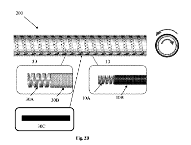
Reference is made to Fig. 2B, illustrating an example of insertion unit 200
comprising an inner elongated shaft structure 30 surrounded by an outer
elongated shaft
structure 10. Inner elongated shaft structure 30 has thus a diameter smaller
than outer
elongated shaft structure 10. It should be understood that inner structure 30
is
configured and operable to transfer rotation around its length axis while
outer structure
10 surrounds the inner elongated shaft structure 30. This special
configuration enables
to transmit torsional forces from an operator's hand to the distal end, such
that the inner
elongated shaft structure 30 rotates inside the outer elongated shaft
structure 10 and
thereby rotates a distal end of the insertion system around itself, without
changing the
outer elongated shaft structure's position inside the body lumen (i.e. without
reshaping
the body lumen). The inner shaft structure 30 and the outer shaft structure 10
are
capable of relative rotation, one with respect to the other, in opposite
directions. The
CA 03117965 2021-04-27
WO 2020/089894 PCT/IL2019/051167
- 15 -
structure of the outer elongated shaft 10 does not have good torque
transmission
capabilities, and therefore does not rotate through the length of the shaft
10, in
particular when it is in a wrapped condition.
The torque transmission capabilities of the inner shaft structure 30 enables
to
transmit torsional forces along the length of the bending section in any
direction even if
the bending section or the insertion unit itself is in a bent (e.g. wrapped or
folded)
position. When a typical rigid tube (continuous) is bent, it is not capable of
transmitting
torsional forces along its length without opening the loop. A flexible tube is
also
generally not capable of good transmission of torsional forces along its
length. The non-
continuous property of the inner shaft structure, together with its
flexibility, enables to
transmit rotational forces along the length of the insertion unit to the
bending section,
even when the insertion unit is bent, due to the natural shape of the body
lumen.
This configuration allows the capability to bend and rotate the distal tip of
an
endoscopic device at minimal force without straightening the body lumen, due
to the
unique torque transfer capabilities of the insertion unit while not affecting
the outer
surface of the shaft. In this connection, it should be noted that conventional
commercially available colonoscopes are not capable of transferring torque if
the shaft
is enwrapped around itself three times, and therefore are not capable of fully
steering
the distal tip. It should be understood that scanning a complicated bent body
lumen such
as a colon, requires appropriate flexibility and restoring performance against
bending,
pushability and torque transmission performance (generically called
"operationality")
for transmitting an operational force from the proximal end portion to the
distal side,
and kink resistance (often called "resistance against sharp bending"). In this
context, in
the specification and in the claims, "proximal" means closer to the orifice -
mouth or
rectum- through which the insertion unit is originally inserted, and "distal"
means
further from this orifice. Therefore, the insertion unit is configured to have
the above-
mentioned properties. More specifically, the pushability means the
characteristics of the
insertion unit that can reliably transmit a pushing force given by an operator
at the base
end of the insertion unit to the distal end thereof. The torque transmission
ability means
the characteristics that can reliably transmit rotational force applied to the
base end of
the insertion unit to the distal end thereof. Further, it is also required for
an insertion
unit to have follow-up characteristics and kink resistance characteristics.
The follow-up
characteristics mean the ability by which the insertion unit can advance
smoothly within
CA 03117965 2021-04-27
WO 2020/089894 PCT/IL2019/051167
- 16 -
a meandered body lumen without causing injury to the body lumen walls. The
physical
properties required for the insertion unit are thus appropriate flexibility (a
certain
flexibility according to the bending radius), follow-up characteristics, a
capability to
rotate the distal end without rotating the entire insertion unit and restoring
performance
against bending, pushability and torque transmission performance (generically
called
"operationality") for transmitting an operational force from the proximal end
portion to
the distal side, and kink resistance (often called "resistance against sharp
bending").
This unique configuration of the inner elongated shaft structure 30 provides
good torque
transfer, high flexibility and free rotation of the distal tip of the device.
As shown in the figure, the inner shaft structure 30 and the outer shaft
structure
10 are capable of relative rotation, one with respect to the other, in
opposite directions.
For example, the bearing structure 60 of Fig. 2A is capable of holding the
inner
elongated shaft 30 and the outer shaft together 10 in both of their edges to
enable
relative rotation, one with respect to the other.
For example, the inner elongated shaft structure and the outer elongated shaft
structure 10 form together an integrated/integral insertion unit connecting at
its
extremities at one side the orientation controller 210 of Fig. 2A and at the
other side the
bending section 310 of Fig. 2A. Inner structure 30 may be attached at one side
to
orientation controller 210 of Fig. 2A and to a bending bearing structure 60 of
Fig. 2A
from the other side. The rotation of the orientation controller rotates the
bending section
in turn. As described above, the outer elongated shaft structure 10 prevents
buckling/kinking and maintains its round shape, while remaining highly
flexible. The
inner elongated shaft structure 30, which does not come into contact with the
body
lumen, rotates inside of the outer shaft structure, without changing the outer
shaft
structure's position inside the body lumen, due to its good torque
transferability and
high flexibility.
Outer elongated shaft structure 10 may be configured as a double layered
structure comprising a coil hollow spring 10A covered by a sleeve/jacket 10B
having a
continuous and optionally flat (e.g. smooth and soft) outer surface. Jacket
10B may be
configured as a flexible sleeve being stiff enough to prevent closure or
kinking and
collapse thereof. The material, the thickness and the structure of the jacket
are selected
accordingly. In a specific and non-limiting example, jacket 10B is made of a
flexible
material such as silicon or thermoplastic e.g. PEBAXTM. The outer surface of
the jacket
CA 03117965 2021-04-27
WO 2020/089894 PCT/IL2019/051167
- 17 -
10B may be soft and smooth and may be coated by a layer having low-friction
properties.
Moreover, in order to effectively exhibit these characteristics, the outer
surface
of the jacket 10B may possess lubrication characteristics.
In some embodiments, jacket 10B is at least partially coated by using a
hydrophilic coating minimizing the frictional forces of the insertion and
improving the
sliding performance of the insertion unit in the body lumen, thereby further
enhancing
operationality of the device the insertion unit is mounted on. In a specific
and non-
limiting example, coil hollow spring 10A may be a flat wire coil spring and
jacket 10B
may be made of a block copolymer such a soft thermoplastic elongated shaft
(e.g.
extruded/over extrusion PEBAXTm), polyurethane (TPU), silicon or other
material. In
this connection, it should be noted that if the jacket is made for example of
silicon, a
coating cannot be applied on its external surface. In this case, a very thin
sleeve made of
another coatable material should be added over the jacket 10B to coat its
external
surface.
Inner structure 30 has flexibility properties and is configured and operable
to
transfer rotation (i.e. torque transmission) around its length axis. Fig. 2B
illustrates two
different possible configurations of the inner structure 30 of the insertion
unit 200. Inner
structure 30 of the insertion unit 200 may comprise a coil hollow spring 30A
covered by
a jacket 30B having a non-continuous outer surface forming together a double
layered
structure. The non-continuous outer surface may be made of a composite
structure and
may have a braided/mesh configuration. Coil hollow spring 30A is capable of
accommodating a plurality of channels running through its length (e.g. for
supplying
water and/or CO2 and/or for suction and/or for supplying electricity and/or
venting fluid
outside the lumen and/or controlling various inflatable device pressures,
and/or sensing
various inflatable device pressures, and/or sensing body lumen's pressures),
as well as
steering threads. Jacket 30B having a braided outer surface, exhibits a
greater effect of
preventing kink. In a specific and non-limiting example, coil hollow spring
10A may be
a flat wire coil spring and jacket 30B may be a stainless steel wire braid.
Alternatively, the inner elongated shaft structure may be implemented by an
elongated torsion shaft 30C surrounded by the outer hollow elongated shaft
structure
10. The torsion shaft may be driven by gearing linked to the output of the
orientation
controller 210 of Fig. 2A. In this connection, it should be understood that,
as described
CA 03117965 2021-04-27
WO 2020/089894 PCT/IL2019/051167
- 18 -
above, the insertion unit of the present invention does not straighten the
body lumen,
and therefore, upon advancing, it will be convoluted around itself according
to the body
lumen shape. However, when a regular tube is bent and convoluted, it is not
capable of
transmitting (i.e. pushing, steering and rotational) forces along its length.
The non-
continuous property of the inner elongated shaft structure enables to transmit
(i.e.
pushing, steering and rotational) forces along the length of the insertion
tube 200A.
When the operator turns orientation controller 210, orientation controller 210
turns the
torsion shaft 30C. This shaft can transfer a great amount of torsion and
remain very
flexible.
Reference is made to Fig. 2C showing a cross sectional view of one possible
configuration of the insertion unit 200A. As shown, torsion shaft 30C can be
placed at
the center of outer hollow elongated shaft structure 10. Since torsion shaft
30C is not
hollow, a plurality of channels may be accommodated between the outer
structure 10
and the torsion shaft 30C. Moreover, torsion shaft 30C is capable of
transmitting torque
even if it is wrapped around itself, because of the loops naturally formed by
the colon.
Moreover, it should be understood that, typically, the operator would prefer
to rotate the
device until the polyp is shown in a 6 o'clock direction to the tool exit
point. If the polyp
is found at the 12 o'clock direction, by using commercially available devices,
the
operator needs to rotate the tool by 1800 to bring the polyp to the desirable
location. To
this end, the operator manipulates the device back and forth, to try to keep
the desired
position, while rotating the tool. This procedure is unsafe and not accurate,
losing the
precise location of the polyp and consuming time. The novel configuration of
the
proposed insertion unit solves the above-mentioned problem. This unique
configuration
of the insertion unit of the present invention enables to provide, together
with steering
capabilities, rotating capabilities, leading to an accurate, rapid and safe
procedure
enabling to target and to treat any precise location of the polyp. As
mentioned above,
this unique configuration provides the capability to convey the polypectomy
tool at any
three-dimensional desired location and position. The insertion unit is capable
of
transferring large torsional forces while bending due to the unique structure.
Reference is made to Fig. 2D, illustrating an example of a medical instrument
in
which the insertion unit of the present invention is incorporated. In this
embodiment, the
insertion unit 200 has a variable/gradual stiffness (e.g. varying elasticity)
along its
length, such that transmission forces applied to the proximal end increase in
the distal
CA 03117965 2021-04-27
WO 2020/089894 PCT/IL2019/051167
- 19 -
direction. This may be implemented by adding at least one flexible wire 22
(e.g.
stainless steel) along the insertion unit length (e.g. through/beside inner
elongated shaft
structure 30). The wires are configured to be flexible enough to be capable to
be bent, if
needed, to fit the body lumen shape. The wires are made of shape memory
material such
as spring steel. For example, in some embodiments, a plurality of wires 22
having
different lengths are incorporated into the insertion unit such that the
elongated shaft
structure's stiffness is divided into a plurality of sections corresponding to
the plurality
of wires 22 having different lengths.
In this context, the variable/gradual stiffness of the elongated shaft
structure
along its length refers to the capability of the insertion unit to keep the
same bending
radius without buckling, while increasing force applied to the insertion unit.
For example, the ratio between the bending radiuses to the insertion unit
radius
is selected to be very low due to the structure of the insertion unit and its
flexibility.
More specifically, the ratio K between the bending radius and the insertion
unit radius is
defined as: K=R/r where R is the bending radius the r is the insertion unit
radius.
In a specific and non-limiting example, K=38.00/6.65; K=5.7
As described above, the pushability and torque transmission performance
defines the force delivery capability of the device between the operator's
hand and the
distal tip of the device. The force delivery capability of the device is a
function of the
depth of insertion into the body lumen of the insertion unit and of the
friction applied on
the insertion unit. When the insertion unit advances within the lumen, the
variable
stiffness of the elongated shaft structure increases linearly together with
the friction
applied on the structure and the depth of the insertion unit in the body lumen
and
therefore with the pushing forces.
Reference is made to Fig. 3A illustrating an example of the configuration of a
bending bearing structure 60 to be connected to the outer elongated shaft
structure at
one side (e.g. by pressure or by adhesive) and to the bending section of the
intubation
system at the other side, according to some embodiments of the present
invention.
Bending bearing structure 60 is configured and operable to provide a rigid
coupling
between the bending section and the outer elongated shaft structure.
The bending bearing structure 60 is capable to rotate, to thereby allow free
rotation of the bending section. To this end, bending bearing structure 60 may
be
formed by first and second elements 60A and 60B coupled to each other. The
first
CA 03117965 2021-04-27
WO 2020/089894 PCT/IL2019/051167
- 20 -
element 60A is static and is configured and operable to be connected to the
outer
elongated shaft structure. The second element 60B is configured and operable
to be
connected to the bending section (e.g. to a steering ring or to the flexible
channel) and
has the capability of rotating around itself, being thus a dynamic element.
For example, bending bearing structure 60 holds the extremities of spring-like
sleeves at least partially enclosing each steering thread as will be described
further
below with respect to of Figs. 5B-5C. In this configuration, the steering
spring-like
sleeves (not shown) may be accommodated within the coil spring 30A of an inner
elongated shaft structure 30 of Fig. 2C and are attached at one extremity to
the bending
bearing structure 60 (e.g. with adhesive). Bending bearing structure 60
comprises a
plurality of openings through which the steering threads can pass towards the
bending
section.
As described above, in some embodiments, the inner elongated shaft structure
may be implemented by an elongated torsion shaft surrounded by the outer
hollow
elongated shaft structure. Reference is made to Fig. 3B illustrating an
example of the
configuration of a bending bearing structure 900 to be connected to the
torsion shaft at
one side (e.g. by pressure or by adhesive) and to the bending section of the
intubation
system at the other side, according to some embodiments of the present
invention. As in
the previous example, bending bearing structure 900 is capable to rotate
around itself in
two directions (clockwise or counterclockwise) to thereby allow free rotation
of the
bending section. To this end, bending bearing structure 900 may be formed by
first and
second elements 900A and 900B (e.g. rings) coupled to each other. The first
element
900A is dynamic and is configured and operable to be connected to the torsion
shaft and
to the bending section and has the capability of rotating around itself. The
second
element 900B is configured and operable to be connected to the outer elongated
shaft
structure. In this specific and non-limiting example, dynamic element 900A
comprises
an opening 910 configured an operable to hold an extremity of the torsion
shaft. For
example, dynamic element 900A may comprise a plurality of openings 912
configured
for accommodating the spring-like sleeves through which the steering threads
can pass
towards the bending section. However, the configuration of the bending bearing
structure 900 is not limited to this configuration. When rotation of the
bending section is
performed by using the torsion shaft, if the angle of rotation is not limited,
the bending
bearing structure 900 would turn around itself and would transfer the
rotational forces,
CA 03117965 2021-04-27
WO 2020/089894 PCT/IL2019/051167
- 21 -
first to the bending section, and thereafter to the insertion unit. This is
because of the
dynamic coupling of the bending bearing structure between the elongated shaft
structure
and the bending section. However, as described above, the insertion unit may
accommodate multiple channels, which might buckle, hindering operation of the
medical instrument. The bending bearing structure 900 is thus configured to
limit the
maximum possible angle of rotation of the bending section. In a specific and
non-
limiting example, the maximum possible angle of rotation of the bending
section may
be around 3400 (about 170 in each direction). Moreover, in some embodiments,
the
bending section and the bending bearing structure may be covered together by a
sealed
sleeve preventing liquid infiltration within the insertion unit. The sleeve
allows the
bending bearing structure to rotate freely until the sleeve starts to stretch
around the
bending section, and applies large forces against the rotation. To this end,
the bending
bearing structure 900 comprises two stoppers 914 positioned in diametrically
opposite
positions being configured and operable to limit the angle of rotation of the
bending
bearing structure 900. If rotation of the bending bearing structure were not
limited, the
resistance forces exerted by the sleeve would stop the rotation and could
deteriorate the
outer surface of the sleeve, possibly leading to a sealing break. However, a
wider range
of rotation (above 340 ) is necessary to allow the operator to inspect every
part of the
body lumen while trying to perform a polypectomy procedure.
In this connection, reference is made to Fig. 3C illustrating another view of
the
example of the bending bearing structure 900 of Fig. 3B above. Bending bearing
900 is
formed by a first and second elements 900A and 900B (e.g. rings) coupled to
each
other. The first element 900A is dynamic and is configured and operable to be
connected to the torsion shaft and to the bending section, and has the
capability of
rotating around itself. The second element 900B is configured and operable to
be
connected to the outer elongated shaft structure. First element 900A comprises
a stopper
914A and second element 900B comprises a stopper 914B being configured and
operable to limit the angle of rotation of the bending bearing structure 900.
The first
element 900A is also able to rotate around itself, until stopper 914A blocks
stopper
914B. As illustrated, after the operator reaches full free rotation of the
bending bearing
structure, stoppers 914B block rotation of the first element 900A, locking the
bending
bearing structure at an angle of about 170 in each direction. The operator
can continue
applying force in the same direction, and the torsional forces applied on the
bending
CA 03117965 2021-04-27
WO 2020/089894 PCT/IL2019/051167
- 22 -
bearing structure, rotates first and second element 900A and 900B together
(stopper
914A pushes stopper 914B) and starts rotating the outer elongated shaft
structure in the
same direction. Full rotation of the bending section will rely only on the
ability of the
torsion shaft (or inner coil) to apply force on the bending bearing structure
which rotates
the far edge of the outer elongated shaft structure. This unique configuration
enables to
rotate the distal tip of the bending section around itself by applying
external rotational
forces on the orientation controller.
As described above, when the bending section is rotated, there is a risk of
damaging the inner channels containing fluids. The insertion unit of the
present
invention enables keeping the channels safe from damage because the rotation
angle is
very small. The torsion shaft rotates the bending bearing structure and starts
rotating the
channels around it until the point of zero rotation. This creates a torsion
angle for a
relatively long distance, minimizing the risk of tubing damages or kinks.
This unique configuration of the insertion unit of the present invention
enables
to provide, together with steering capabilities, rotating capabilities leading
to an
accurate, rapid and safe procedure enabling to target and to treat any precise
location of
the polyp. As mentioned above, this unique configuration provides the
capability to
convey the polypectomy tool at any three-dimensional desired location and
position. In
some embodiments, the bending section comprises spaced-apart steering rings
fixed on
the internal space of an external mesh braided sleeve structure. Rotation of
the bending
section at the same angle as the bending bearing structure is possible due to
the braided
sleeve structure of the bending section. The bending section structure is
capable of
transferring large torsion forces while bending due to the unique structure of
the braided
sleeve having a mesh flexibility structure. The braided sleeve structure can
be made
from different types of material (plastics, metals), and have a different
types of structure
(angle, wires).
This unique configuration provides, to the bending section, the capability to
bend at an angle exceeding 180 in every direction. This angle can be achieved
due to
the flexibility of the bending section, the low forces required to be applied
to reach this
angle, and the structure of the bending section. The flexibility of the
bending section is
due to the structure of the bending section of the present invention. In
particular, the
steering rings and the braided structure allow maximum movement without
locking.
The bending section allows the operator to rotate the orientation controller
and reach
CA 03117965 2021-04-27
WO 2020/089894 PCT/IL2019/051167
- 23 -
maximum angle without locking the mechanism. Due to the structure and the
flexibility
of the bending section (i.e. flexible tubes accommodated inside the bending
section), the
materials of the bending section's elements and the thin layer on top of the
braided
sleeve, the forces required to reach maximum angle and a very small bending
radius
(inner radius of about 10 mm and outer radius being equal to about the inner
radius and
the diameter of the steering elements as will be described below e.g. 24 mm)
are very
low as compared to other conventional colonoscopes commercially available.
Reference is made to Fig. 4A illustrating a configuration of the intubation
system 300, in which the elongated shaft structure has several bent regions
fitting the
natural shape of the body lumen. As described above, rotation of the torsion
shaft
causes, firstly, the bending section 310 to rotate together with the optical
head. Because
the outer elongated shaft 10 is not connected to the dynamic element of the
bending
bearing (900A of Fig. 3B) and is continuous and very flexible, the structure
of the outer
elongated shaft 10 does not have good torque transmission capabilities, and
therefore
does not rotate through the length of the shaft 10, in particular when it is
in a wrapped
condition. After the bending section has been rotated at the maximal angle as
described
above, if the operator decides to continue to apply rotational forces on the
insertion unit,
the outer shaft 10 rotates by the movement of stopper 914A of the dynamic
element
900A of Fig. 3B that pushes the stopper 914B of the static element 900B in the
bending
bearing structure (60 of Fig. 3A) that connected to the outer elongated shaft.
The
insertion unit can be easily rotated until the point of zero rotation R which
is the last
bending point of the outer shaft (or the connection between the orientation
controller
and the outer shaft if the outer shaft is straight). After point of zero
rotation R, the
proximal portion of the outer shaft 10 does not rotate around itself.
Reference is made to Fig. 4B illustrating the angle of rotation of the outer
shaft
in each section as a function of the length X between the orientation
controller and the
bending section, using the insertion unit of the present invention. Fig. 4C
illustrates the
stiffness of the insertion unit as a function of the length of the insertion
unit. It is shown
in the figure, that in case that the operator applies torsional forces on the
insertion unit,
after the bending section has been rotated at the maximal angle, the stiffness
of the
region between the bearing structure to the point of zero rotation increases.
Reference is made to Figs. 5A-5B exemplifying one possible configuration of
the bending section 310 of the present invention comprising elements 412
having a
CA 03117965 2021-04-27
WO 2020/089894 PCT/IL2019/051167
- 24 -
closed-loop configuration surrounded by a flexible channel 410 and configured
to be
threaded by the steering threads 414 forming. The bending section refers
hereinafter to
the section of the intubation system in which closed-loop elements are
accommodated.
This section enables deflection of the distal tip in four main directions.
Deflection of the
distal tip is necessary to ease intubation, scanning and removal of polyps.
The bending
section 310 may be an integral part of an endoscopic system.
Although the elements 412 are represented as having a ring-like shape
configuration, any shape matching the external shape of the insertion unit may
also be
used.
Fig. 5A exemplifies the straight state (non-bent) in which the rings do not
touch
each other. The combination of the flexible channel 410 and spaced-apart
elements 412
provides a steerable bending section having bending and torsion properties
even in a
bent state. The bending and torsion properties are obtained due to the special
configuration of the bending section of the present invention comprising
spaced-apart
elements not linked by a mechanical connection. The material used for this
portion has
the following physical properties: low bending forces (shear and normal
stress), rotating
capabilities, and small bending radius. For example, such material may be a
braided
sleeve made from PET, Nylon, Mylar, Vinyl, Polyolefin, PVDF, Polyethylene,
Silica,
Aramid, PEEK, PPS, PFA, ECTFE, Copper, Stainless Steel, Brass or a blocked
sleeve
made from any elastomer or polymer.
The flexible channel 410 may be a flexible sleeve on which the spaced-apart
elements 412 are provided along its length for increased stiffness and to help
prevent
kink and collapse of the sleeve. In some embodiments, the external surface of
the
flexible channel may be smooth, flat (without protrusion) facilitating
navigation and
insertion into a body lumen, and also contributing to the ease of applying low
friction
coatings (hydrophilic/hydrophobic), when needed. The flexible channel 410 is
configured as a jacket which may have at least one of the following
configurations: a
thin-walled tubular member, and a braided sleeve. Therefore, in some
embodiments, the
bending section of the present invention is capable of full steering, as well
as full
rotation around itself, providing accurate imaging and polypectomy.
In some embodiments, the bending section can be manipulated by at least two
pulling threads, enabling full control of the steering of the bending section
at any
desired angle. In a specific and non-limiting example, steering of the optical
head is
CA 03117965 2021-04-27
WO 2020/089894 PCT/IL2019/051167
- 25 -
implemented by pulling and releasing at least two steering threads 414
attached to the
optical head at one side of the device, and at one pulley at the other. Each
steering
thread 414 bends the bending section in one steering direction. Each steering
thread 414
is configured to transfer a pulling force to the distal end of the bending
section in order
to bend it. One end of each steering thread 414 is rigidly fixed to the
flexible channel
(shown as S in Fig. 5D below) or to the outermost spaced-apart element, while
the other
end of the steering thread 414 is free to move (shown as S' in Fig. 5D below).
The
steering threads 414 are configured and operable to steer the bending portion
310 in
which the spaced apart elements 412 are incorporated, by pulling at least one
end of at
least one steering thread 414.
Moreover, the steering threads 414 and the spaced-apart elements 412 are
located inside of the flexible channel 410, which protects them from
environment
factors (such as moisture, heat, acids, etc.). Furthermore, for spaced-apart
elements
having the same dimension, this novel configuration in which the plurality of
spaced-
apart elements are surrounded by the flexible channel, leaves more space in
the volume
defined by the inner surface of the spaced-apart element than when the spaced-
apart
elements are positioned over the flexible channel. In this connection, it
should be noted
that the space/volume available within the channel is an important parameter
of the
system, since, typically, a bending section is associated with a plurality of
tubes passing
therethrough. As described above, the plurality of tubes passing therethrough
may be
configured for at least one of supplying water, supplying electricity, venting
fluid
outside the lumen, and controlling various inflatable device ("balloon")
pressures,
sensing various inflatable device ("balloon") pressures, and sensing body
lumen's
pressures (e.g., sensing pressure distal to apparatus).
In some embodiments, the spaced-apart elements 412 may be fastened to the
inner surface of the flexible channel by adhesion. The spaced-apart elements
412 may
be rigidly fastened along the flexible channel 410. Fastening of the elements
on the
flexible channel may be carried out by any suitable method, for example by at
least
partially applying adhesive material on the steering element by ultrasonic
welding or by
injection molding. The spaced-apart elements 412 may be maintained by the
flexible
channel or rigidly fastened along the channel. The spaced-apart elements 412
may be
separated by a variable or constant distance between them. The distance
between the
elements determines the properties of the bending section such as its
flexibility and
CA 03117965 2021-04-27
WO 2020/089894 PCT/IL2019/051167
- 26 -
bending properties as well as the shape of the bent tip. The distance between
the spaced-
apart elements is determined according to the specific material of the
flexible channel.
Fig. 5B exemplifies a fully bent state in which the ring's edges come into
contact. Pulling a steering thread 414 causes bending momentum in all the
rings that it
passes through. In this configuration, the steering threads 414 are thus also
surrounded
by the flexible channel protecting them from interaction with the
surroundings. This
ability of protecting the steering threads and the spaced-apart elements from
contact
with the body lumen, enables to use a large range of materials for
manufacturing the
steering threads and the spaced-apart elements which do not have to be in
compliance
with requirements for materials being inserted into a body lumen.
As described above, the appropriate selection of distance between the steering
elements enables an optimal steering in any direction, and at any angle. The
amount of
the spaced-apart elements 412 may be variable and depends on the required
maximal
bending radius, channel flexibility and the width of each spaced-apart
element.
The bending section provides the steering capability of being displaced to any
steering direction, and being bent to any angle. The bending of the bending
section is
provided by compressing one side (the bending side) and stretching the other
(outer to
the bend).
Reference is made to Fig. 5C exemplifying a cross-sectional view of the ring-
like element 412. As exemplified in Figs. 5A-5B, in some embodiments, the ring-
like
element is configured such that its cross-sectional shape defines a tapered
section from
both sides to ensure that while in a bent state when pulling on the steering
threads, a U-
shape of the channel would be achieved to prevent the creation of elbows or
folded
portions. In this specific and non-limiting example, the ring-like element has
four
.. openings 412A positioned radially at equal angles one from another (at 90 )
through
which at least a portion of the steering threads is intended to pass. However,
the
invention is not limited to such a configuration and the number of openings
may be two
or three. Generally, each ring contains at least two openings positioned
radially at equal
angles, one from another. The rings are stacked, one above the other, such
that the
openings are arranged in a concentric manner. A steering thread is threaded
through all
concentric holes of all the rings, one thread per each steering direction. The
outer
surface 412B of the ring-like element is surrounded by the flexible channel.
As
described above, the ring-like element may be enclosed by the flexible channel
or may
CA 03117965 2021-04-27
WO 2020/089894 PCT/IL2019/051167
- 27 -
be fastened to the inner surface of the flexible channel. The flexible channel
is thus
configured as a sleeve enclosing the plurality of spaced-apart elements and
protecting
them from contact with the surroundings. Contact of the bending section with
the body
lumen is thus made via the external surface of the flexible channel, being a
flat surface
without indentation or protrusion, which facilitates insertion and navigation
of the
device/tool on which it is mounted. The flexible channel may be then coated by
a
hydrophilic solution for reducing friction forces during advancement of the
device. In
case of a braided sleeve, it might be covered by a very thin sleeve and the
coating will
be applied on it.
Reference is made to Fig. 5D exemplifying a partial view of a bending section
400 according to some embodiments of the present invention. In some
embodiments,
each steering thread 414 may be at least partially enclosed by a spring-like
sleeve 11
respectively. The extremities of the sleeves are fixed to the non-steerable
portion B of
the guiding tube 10 at two points 11A and 11B. As described above, one end of
each
steering thread 414 is rigidly fixed to the flexible channel (shown as S) or
to the
outermost spaced-apart element, while the other end of the steering thread 414
is free to
move (shown as S'). As described above, the bending bearing structure 60 of
Fig. 3A
may hold the extremities of spring-like sleeves at least partially enclosing
each steering
thread. The portion of the steering threads 414 passing through the spaced-
apart
elements 412 may not be enclosed by the sleeves 11 while the remaining portion
may be
enclosed by the sleeves 11. The sleeves 11 may be flexible closed coil spirals
having an
incompressible part that allow sliding movement of steering threads inside.
The steering
threads 414 at least partially enclosed by the spring-like sleeves 11 may be
configured
as a Bowden cable. It should be noted that, as is well known in the art, a
Bowden cable
is a type of flexible cable used to transmit mechanical force or energy by the
movement
of an inner cable (most commonly of steel or stainless steel) relative to a
hollow outer
cable housing. In the present invention, the inner cable is the steering
thread and the
housing is the spring-like sleeves. The housing is generally of composite
construction,
consisting of a helical steel wire, often lined with nylon, and with a plastic
outer sheath.
The linear movement of the inner cable is most often used to transmit a
pulling force.
Therefore, the spring-like sleeve 11 may be made of a close-wound helix of
round or
square steel wire.