Note: Descriptions are shown in the official language in which they were submitted.
CA 03118019 2021-04-28
WO 2020/108713 PCT/D1(2019/050355
1
An agricultural work vehicle
Field of the invention
The present invention relates in general to the field of agriculture. More
specifically the
present invention relates in a first aspect to an agricultural work vehicle
for performing an
agricultural work operation. In a second aspect the present invention relates
to a use of an
agricultural work vehicle according to the first aspect for performing an
agricultural work
operation.
Background of the invention
Within the field of agriculture, it has traditionally been common practice to
provide auxiliary
power when performing agricultural work, such as during tillage. Such
auxiliary power had
for centuries been provided by relatively large animals, such as cattle,
horses, donkeys etc.
During the 1940s and the 1950 the use of tractors for aiding soil working
became very
popular and tractors eventually outperformed the use of towing animals.
Tractors provide many benefits compared to use of work animals. These benefits
comprise
inter alia increased power, no exhaustion during prolonged working periods,
full obedience to
the operator's instructions etc.
Because tractors are manually operated, thus needing an operator during use
thereof, it makes
sense that tractors are designed with the current relatively large size. The
rationale is: because
a tractor needs a human operator, tractors might just as well be designed in a
size that allows
working a relatively large width of agricultural soil, thereby reducing the
time needed for
human interference. Hence, it is not uncommon that currently produced tractors
are having
sizes that allows for working the agricultural field in a width of 1 ¨ 50
meters or more.
Although the rather large sizes of currently produced tractors provide for
efficient working of
an agricultural field, these tractors nevertheless present a number of
disadvantages.
One of these disadvantages is that the large size of these tractors and the
accompanying high
weight imposes a not insignificantly soil compaction. Any soil compaction is
undesirable
CA 03118019 2021-04-28
WO 2020/108713 PCT/D1(2019/050355
2
because it prevents optimal growth conditions of crops growing in the soil or
to crops to be
sown in the soil.
The larger the machines becomes, the more difficult it is for the human
operator to apply the
needed attention to the individual square meter of the field. Hence the fields
therefore are
being managed more according to a plan and not to the site-specific conditions
and needs.
With the recent advances of robot technology, autonomous agricultural working
vehicles (or
autonomous agricultural robots) have been developed. Such autonomous
agricultural work
vehicles may be able to perform tillage operations, spraying operations,
seeding operations,
weeding operations and other types of agricultural operations.
Additionally, such robots are particularly well suited for performing sensor-
based surveying
of an agricultural field with the view to gain information of the general
state of such field, the
soil and its crops.
These agricultural robots may be programmed to follow a predetermined path in
the
agricultural field upon working it but can also be equipped with a system for
adaptive route
planning for in-field optimization of the specific operation, thereby avoiding
the necessity of
human intervention during its operation.
As such robots are autonomous and therefore does not require human operation
during the
working thereof, it is not a decisive factor to design the robots in a size
that has the same
working capacity as the currently available tractors in order to maintain a
competitive cost-
.. efficient operation.
One type of an agricultural robot has been manufactured and marketed by the
proprietor of the
present application, under the trade name "Robotti".
Robotti comprises two drive modules with wheels, arranged sideways relative to
the direction
of movement. Each of the two drive modules are rigidly fixed to opposite ends
of a front bar
having a fixed axial extension. On the front bar, between the two drive
modules, is arranged a
three-point linkage which allows an agricultural implement to be coupled to
the front bar of
Robotti.
Each drive module comprises two broad wheels arranged behind one another. Each
wheel
comprises a hub including a hydraulic drive. Both of the drive modules
comprise a diesel
CA 03118019 2021-04-28
WO 2020/108713 PCT/D1(2019/050355
3
engine coupled to a hydraulic pump which provides pressurized hydraulic fluid
to be supplied
to the hydraulic drives of the wheels.
A control system provides for controlling Robotti. The control system is being
configured to
control the movement of Robotti according to the operational specifications to
be followed.
With the relative low weight of Robotti, its broad wheels and tires, Robotti
imparts
considerably less soil compaction to the soil, compared to the situation
encountered by
conventional tractors.
However, although Robotti represents huge advances in the field of
agriculture, this robot
nevertheless leaves room for improvement.
One of these disadvantages is that prior art Robotti work vehicle is having
engines,
hydraulics, and fuel tanks, batteries etc. arranged in each individual drive
module. Thereby, in
respect of both the drive modules, no free space is available near the level
of the chassis of the
drive modules. Accordingly, the prior art Robotti work vehicle is not in
itself capable of
transporting lose loads, such as solutions for chemical sprayers, fertilizers
for fertilizer
equipment and seeds for seed drills.
The prior art Robotti also represents limitations due to its height in e.g. a
harvest operation
involving sideways offload to a transport vehicle during movement is required.
Such
harvesting operations may be harvesting of grass, potatoes or other
vegetables.
Accordingly, a need exists for an improved autonomous agricultural work
vehicle which
overcomes the above identified disadvantage.
It is an objective of the present invention to provide an improved
agricultural work vehicle
which overcomes the above listed disadvantage.
Brief description of the invention
This objective is fulfilled according to the first and the second aspect of
the present invention.
Accordingly, the first aspect of the present invention relates to an
agricultural work vehicle
for performing an agricultural work operation in an agricultural field,
wherein said work
vehicle comprises:
CA 03118019 2021-04-28
WO 2020/108713 PCT/D1(2019/050355
4
-a first drive module;
-a second drive module;
-a connecting element; said connecting element comprises a first axial end and
a
second axial end;
-propulsion means for propelling said work vehicle;
-steering means for steering said work vehicle;
-a control unit for controlling the operation of said work vehicle;
wherein said first drive module comprises a first chassis;
wherein said second drive module comprises a second chassis;
wherein said first drive module comprises drive means for allowing said first
drive module to
move over ground, said drive means being suspended on said first chassis;
wherein said second drive module comprises drive means for allowing said
second drive
module to move over ground, said drive means being suspended on said second
chassis;
wherein said first axial end of said connecting element is being attached to
said first chassis;
and wherein said second axial end of said connecting element is being
connected to said
second chassis;
wherein one of said two drive modules comprises a load carrying platform
arranged at the
corresponding chassis.
In a second aspect the present invention relates to the use of an agricultural
work vehicle
according to the first aspect for performing an agricultural work operation.
The present invention in its various aspects provides for improved
flexibility, compared to the
prior art Robotti work vehicle in that the agricultural work vehicle of the
present invention
provides for allowing transporting rather large and heavy loads. This feature
is beneficial in
various agricultural situations, such as transportation of water or solutions
for sprayers,
fertilizers for fertilizer equipment and seeds for seed drills.
CA 03118019 2021-04-28
WO 2020/108713 PCT/D1(2019/050355
Furthermore, the inventive work vehicle allows sideways offload to a transport
vehicle during
movement in a harvesting operation. Such harvesting operations may be
harvesting of grass,
potatoes or other vegetables.
5 Brief description of the figures
Fig. la is a perspective view illustrating an agricultural work vehicle
according to the prior
alt
Fig. lb is a perspective view illustrating an agricultural work vehicle
according to the prior
art, with its covers removed.
Fig. 2a is a perspective view illustrating an agricultural work vehicle
according to the present
invention.
Fig. 2b is a top view illustrating the inventive agricultural work vehicle
shown in Fig. 2a.
Fig. 2c is a front view illustrating the inventive agricultural work vehicle
shown in Fig. 2a.
Fig. 2d is a side view inventive agricultural work vehicle shown in Fig. 2a.
Fig. 2e is a is a perspective view illustrating an agricultural work vehicle
according to the
present invention with its cover removed.
Fig. 3 is a schematic diagram illustrating the principle of the working mode
of the control unit
of the agricultural work vehicle of the present invention.
Detailed description of the invention
The first aspect of the present invention
The first aspect of the present invention relates to an agricultural work
vehicle for performing
an agricultural work operation in an agricultural field, wherein said work
vehicle comprises:
-a first drive module;
-a second drive module;
CA 03118019 2021-04-28
WO 2020/108713 PCT/D1(2019/050355
6
-a connecting element; said connecting element comprises a first axial end and
a
second axial end;
-propulsion means for propelling said work vehicle;
-steering means for steering said work vehicle;
-a control unit for controlling the operation of said work vehicle;
wherein said first drive module comprises a first chassis;
wherein said second drive module comprises a second chassis;
wherein said first drive module comprises drive means for allowing said first
drive module to
move over ground, said drive means being suspended on said first chassis;
wherein said second drive module comprises drive means for allowing said
second drive
module to move over ground, said drive means being suspended on said second
chassis;
wherein said first axial end of said connecting element is being attached to
said first chassis;
and wherein said second axial end of said connecting element is being
connected to said
second chassis;
wherein one of said two drive modules comprises a load carrying platform
arranged at the
corresponding chassis.
It should be noted that in the present description and in the appending claims
it is understood
that generally the one drive module which comprises the load carrying platform
may either be
the left drive module or the right drive module (when viewed in a driving
direction where the
connecting element is facing the driving direction). However, there may be
situations in
which it is preferred that the load carrying platform is arranged specifically
at the right hand
drive module or at the left hand drive module.
Accordingly, depending of specific needs, the inventive agricultural work
vehicle may be
designed in either geometry.
In an embodiment of the agricultural work vehicle according to the first
aspect of the present
invention the agricultural work vehicle is being a remotely controlled work
vehicle and/or an
autonomous work vehicle and/or a semi-autonomous work vehicle.
CA 03118019 2021-04-28
WO 2020/108713 PCT/D1(2019/050355
7
Hereby is achieved that the agricultural operation can be performed remotely
controlled,
autonomous or semi-autonomous. In the present description and in the appended
claims a
semi-autonomous mode shall be construed to mean an autonomous mode in which an
operator may overrule autonomy by remotely providing remote and manual
operational
instructions during its autonomous operation.
In an embodiment of the agricultural work vehicle according to the first
aspect of the present
invention the propulsion means comprises one or more electric motors or one or
more
hydraulic drives or one or more mechanical drives for driving said drive
means.
These types of propelling the work vehicle have proven beneficial.
In an embodiment of the agricultural work vehicle according to the first
aspect of the present
invention the drive means each comprises two or more sets of wheels, wherein
all wheels in a
specific set of wheels are sharing a common axis of rotation; or wherein said
drive means
each comprises one or two or more caterpillar belts.
Wheels and caterpillar belts have proved simple and cost efficient way of
propelling the
.. agricultural work vehicle.
In an embodiment of the agricultural work vehicle according to the first
aspect of the present
invention the drive means each comprises two sets of wheels, said sets of
wheels being
arranged behind each other, as seen relative to a non-turning direction of
movement of said
vehicle.
In an embodiment of the agricultural work vehicle according to the first
aspect of the present
invention the set of wheels, in respect of a specific set of wheels, comprises
one, two, three, or
four or more wheels.
In an embodiment of the agricultural work vehicle according to the first
aspect of the present
invention the drive means comprises one, two, three, or four or more
caterpillar belts,
optionally being arranged sideways to each other and/or behind each other.
In an embodiment of the agricultural work vehicle according to the first
aspect of the present
invention the propulsion means are configured for driving one or two sets of
wheels or
caterpillar belts of each drive module.
CA 03118019 2021-04-28
WO 2020/108713 PCT/D1(2019/050355
8
In an embodiment of the agricultural work vehicle according to the first
aspect of the present
invention the propulsion means comprises hydraulic drives for driving said
drive means and
the agricultural work vehicle comprises one or more hydraulic pumps for
driving said
hydraulic drives, and the agricultural work vehicle furthermore comprises a
motor for driving
the hydraulic pump, such as an electric motor; or a combustion engine, such as
a petrol engine
or a diesel engine, or a biogas engine.
In an embodiment of the agricultural work vehicle according to the first
aspect of the present
invention the propulsion means comprises an electric motor for driving said
drive means.
In an embodiment of the agricultural work vehicle according to the first
aspect of the present
invention the propulsion means comprises mechanical means for driving said
drive means.
In these three embodiments the agricultural work vehicle may be propelled
using hydraulic,
electric or mechanic technology.
In an embodiment of the agricultural work vehicle according to the first
aspect of the present
invention one or more of said wheels independently is/are having an outer
diameter of 25 -
300 cm, such as 30 ¨ 275 cm, for example 35 ¨ 250 cm, such as 40 ¨ 225 cm,
e.g. 45 ¨ 200
cm, such as 50 ¨ 175 cm, e.g. 55 ¨ 150 cm, such as 60 ¨ 125 cm, e.g. 65 ¨ 100
cm, such as 70
¨ 95 cm, such as 75 ¨ 90 cm, e.g. 80 ¨ 85 cm.
In some environments it is preferably to provide the agricultural work vehicle
with wheels
having a relatively large diameter and in other environments it is preferably
to the agricultural
work vehicle with smaller wheels. The above ranges cover most situations.
In an embodiment of the agricultural work vehicle according to the first
aspect of the present
invention at least one set of wheels of each drive module is being pivotally
suspended in a
wheel base on its corresponding chassis in such a way that the pitch of the
rotational plane of
said one or more wheels of said set of wheels can be altered, relative to a
fixed geographical
direction, and wherein said steering means comprises actuation means for
altering said pitch.
This design provides for a reliable mode of steering the agricultural work
vehicle. In an
embodiment of the agricultural work vehicle according to the first aspect of
the present
invention the steering means comprises means for allowing propelled wheels of
one drive
module to rotate at a rotational speed which is different from the rotational
speed of the
propelled wheels of the other drive module.
CA 03118019 2021-04-28
WO 2020/108713 PCT/D1(2019/050355
9
This design provides for another reliable mode of steering the agricultural
work vehicle. In
certain embodiments the above two steering modes may be combined. In an
embodiment of
the agricultural work vehicle according to the first aspect of the present
invention the shortest
distance from the center of a wheel of one drive module to the center of a
wheel of the other
drive module is selected from the range 20 - 4000 cm, such as 30 ¨ 3500 cm,
e.g. 40 ¨ 3000
cm, such as 50 ¨ 2500 cm, for example 60 ¨ 2000 cm, e.g. 70 ¨ 1800 cm, such as
80 ¨ 1700
cm, e.g. 90 ¨ 1600 cm, for example 100 ¨ 1500 cm, e.g. 150 ¨ 1400 cm, e.g. 200
¨ 1300 cm,
such as 250 ¨ 1200 cm, such as 300 ¨ 1100 cm, such as 350 ¨ 1000 cm, such as
400 ¨ 900
cm, such as 500 ¨ 800 cm, e.g. 600 ¨ 700 cm.
The above widths of the agricultural work vehicle have proven appropriate for
the intended
purpose of performing an agricultural operation.
In an embodiment of the agricultural work vehicle according to the first
aspect of the present
invention the work vehicle further is comprising an energy storage or energy
provider, such as
a fuel tank or a battery; or one or more solar panels; or one or more fuel
cell modules in
combination with a fuel gas tank, such as a hydrogen tank or a methane tank.
These energy sources have proven beneficial for a work vehicle according to
the first aspect
of the invention.
In an embodiment of the agricultural work vehicle according to the first
aspect of the present
invention the work vehicle further comprising coupling means for allowing
coupling to said
agricultural work vehicle of an agricultural implement, said coupling means
optionally being
arranged at or on said connecting element, said coupling means optionally
being in the form
of a three-point hitch or in the form of an A-frame.
In an embodiment of the agricultural work vehicle according to the first
aspect of the present
invention the first drive module and said second drive module are having an
elongate shape.
It has proved beneficial to design each drive module with an elongate shape
having its longest
dimension in the driving direction.
In an embodiment of the agricultural work vehicle according to the first
aspect of the present
invention the first axial end of said connecting element is attached to said
first chassis of said
first drive module at an end thereof; and wherein said second axial end of
said connecting
element is attached to said second chassis of said second drive module at an
end thereof.
CA 03118019 2021-04-28
WO 2020/108713 PCT/D1(2019/050355
Hereby the connecting element will be arranged near an extreme end of the
agricultural work
vehicle.
In an embodiment of the agricultural work vehicle according to the first
aspect of the present
invention the first drive module and said second drive module are arranged
essentially in a
5 parallel orientation relative to each other.
In an embodiment of the agricultural work vehicle according to the first
aspect of the present
invention the first drive module and said second drive module are arranged
relative to each
other in such a way that a free space is being present between part of said
first drive module
and part of said second drive module.
10 Hereby is assured that there is providing room for an agricultural
implement in the free space
between the drive modules.
In an embodiment of the agricultural work vehicle according to the first
aspect of the present
invention the free space between the first drive module and the second drive
module in a
region appearing in a direction perpendicular to the connecting element, such
as in a forward
pointing direction and/or in a rearward pointing direction, is devoid from any
element
connecting said first drive module to said second drive module.
Hereby is assured that no elements prevent or impair the operation of an
agricultural
implement being arranged between the two drive modules.
In an embodiment of the agricultural work vehicle according to the first
aspect of the present
invention each drive means is being rigidly suspended at or on its
corresponding chassis, i.e.
in a non-spring-loaded manner.
By providing the pivoting means as defined according to the first aspect of
the present
invention, expenses for manufacturing spring-loaded suspensions of the drive
means can be
avoided altogether, thereby reducing manufacturing costs.
.. Alternatively, each drive means may be suspended at or on its corresponding
chassis in a
spring-loaded manner.
In an embodiment of the agricultural work vehicle according to the first
aspect of the present
invention the work vehicle comprises a monitoring unit for visually monitoring
soil and/or
vegetation during operation thereof.
CA 03118019 2021-04-28
WO 2020/108713 PCT/D1(2019/050355
11
Hereby the agricultural work vehicle according to the first aspect of the
present invention can
be used for surveying operations in an agricultural field.
In an embodiment of the agricultural work vehicle according to the first
aspect of the present
invention the work vehicle comprises means for allowing, during driving a
curved trajectory,
the outer drive means, such as the outer wheels, to rotate a higher angular
velocity, compared
to the inner drive means, such as the inner wheels.
Hereby a minimum degree of adverse physical impact is imposed to the soil.
In an embodiment of the agricultural work vehicle according to the first
aspect of the present
invention the part of the propulsion means providing the power for propelling
said
agricultural work vehicle is being solely arranged on said first drive module.
Hereby can be s assured that there will be enough free space at the second
drive module so as
to allow arranging the load carrying platform at the second drive module.
In an embodiment of the agricultural work vehicle according to the first
aspect of the present
invention the control unit is being solely arranged at said first drive
module.
Hereby can be s assured that there will be enough free space at the second
drive module so as
to allow arranging the load carrying platform at the second drive module.
In an embodiment of the agricultural work vehicle according to the first
aspect of the present
invention any energy storage or energy provider, such as a fuel tank or a
battery; or one or
more solar panels; or one or more fuel cell modules in combination with a fuel
gas tank, such
as a hydrogen tank or a methane tank, is/are being solely arranged at said
first drive module.
Hereby can be s assured that there will be enough free space at the second
drive module so as
to allow arranging the load carrying platform at the second drive module.
In an embodiment of the agricultural work vehicle according to the first
aspect of the present
invention the load carrying platform defines an upper surface having an
extension in a
longitudinal direction of 100 ¨ 4000 cm, such as 150 ¨ 3500 cm, e.g. 200 ¨
3000 cm, for
example 250 ¨ 2500 cm, such as 300 ¨ 2000 cm, e.g. 400 ¨ 1500 cm, e.g. 500 ¨
1000 cm.
In an embodiment of the agricultural work vehicle according to the first
aspect of the present
invention the load carrying platform comprises an upper surface having an
extension in a
CA 03118019 2021-04-28
WO 2020/108713 PCT/D1(2019/050355
12
transverse direction of 25 ¨ 1500 cm, such as 50 ¨ 1200 cm, e.g. 100 ¨ 1000
cm, such as 150
¨ 800 cm, e.g. 200 ¨ 700 cm, such as 300 ¨ 600 cm or 400 ¨ 500 cm.
These dimensions of the load carrying platform have proven beneficial for the
purpose of
carrying loads in an agricultural field.
In an embodiment of the agricultural work vehicle according to the first
aspect of the present
invention the load carrying platform defines an upper surface which is being
arranged at a
level above ground of 20 ¨ 200 cm, such as 25 ¨ 175 cm, e.g. 50 ¨ 150 cm, such
as 75 ¨ 125
cm.
The lower height at which the load carrying platform is arranged, the easier
it will be to
handle loads arranged thereon. The listed dimensions have proven suitable.
In an embodiment of the agricultural work vehicle according to the first
aspect of the present
invention the load carrying platform is being arranged at a level above said
drive means of
said second drive module.
Hereby the work vehicle takes up a minimum of space in the horizontal plane.
In an embodiment of the agricultural work vehicle according to the first
aspect of the present
invention the load carrying platform is being arranged above said second
chassis of the
second drive module; or wherein said load carrying platform is integrated with
said second
chassis of said second drive module.
In an embodiment of the agricultural work vehicle according to the first
aspect of the present
invention the load carrying platform defines an upper surface having a
rectangular shape.
A rectangular shape is a common shape for a load carrying platform employed in
the field of
transportation and agriculture.
In an embodiment of the agricultural work vehicle according to the first
aspect of the present
invention the load carrying platform comprises one or more essentially
vertical sides, such as
detachable sides, for securing goods being arranged on said platform.
Hereby goods being carried can be prevented from falling off the load carrying
platform.
In an embodiment of the agricultural work vehicle according to the first
aspect of the present
invention the second drive module is devoid of any of the following: the part
of the
CA 03118019 2021-04-28
WO 2020/108713 PCT/D1(2019/050355
13
propulsion means providing the power for propelling said agricultural work
vehicle; said
control unit; any energy storage or energy provider, such as a fuel tank or a
battery; or one or
more solar panels; or one or more fuel cell modules in combination with a fuel
gas tank, such
as a hydrogen tank or a methane tank.
Hereby can be s assured that there will be enough free space at the second
drive module so as
to allow arranging the load carrying platform at the second drive module.
In an embodiment of the agricultural work vehicle according to the first
aspect of the present
invention the upper surface of said load carrying platform is being
essentially planer.
In an embodiment of the agricultural work vehicle according to the first
aspect of the present
.. invention the upper surface of said load carrying platform is being
essentially horizontally
arranged at said drive module.
Hereby large items can easily be accommodated on the platform.
In an embodiment of the agricultural work vehicle according to the first
aspect of the present
invention, the load carrying platform and/or the chassis comprising said load
carrying
platform comprises one or more fastening means for fastening goods to be
transported on said
platform, such as in the form of hooks, rings or the like for fastening one or
more straps.
In an embodiment of the agricultural work vehicle according to the first
aspect of the present
invention, the space above said load carrying platform is devoid of any parts
relating to said
agricultural work vehicle, thereby defining a free space above said load
carrying platform.
In an embodiment of the agricultural work vehicle according to the first
aspect of the present
invention, an upper surface of said load carrying platform defines the highest
surface of the
drive module on which said load carrying platform is being arranged.
In an embodiment of the agricultural work vehicle according to the first
aspect of the present
invention the work vehicle further comprising an agricultural implement for
performing an
agricultural work operation.
In an embodiment of the agricultural work vehicle according to the first
aspect of the present
invention the agricultural implement is being selected from the group
comprising: a tillage
implement, a harrow, a seed drill, a cultivator, a weeder, a sprayer, a
fertilizer spreader, an
irrigator, a harvesting implement.
CA 03118019 2021-04-28
WO 2020/108713 PCT/D1(2019/050355
14
Hereby a vast array of various agricultural operations may be performed.
In an embodiment of the agricultural work vehicle according to the first
aspect of the present
invention the work vehicle further comprising a monitoring unit for monitoring
the operation
of said work vehicle.
Hereby can continuously be controlled whether or not the work vehicle and/or
its attached
implement operates is a desired mode.
In an embodiment of the agricultural work vehicle according to the first
aspect of the present
invention the control unit is being configured for receiving and storing
information on a data
storage, relating to one or more of the following: geographic coordinates
relating to the
boundary of an agricultural field to be worked; geographic coordinates
relating to the
boundary of one or more obstacles being present in an agricultural field to be
worked;
geographic coordinates relating to a preferred trajectory to be followed by
said agricultural
work vehicle; information relating to the effective working width of an
agricultural implement
to be carried/towed by said agricultural implement; information relating to
the interrow
distance between rows of crops in the agricultural field to be worked.
Hereby it is possible to instruct the work vehicle to follow a predetermined
route on an
agricultural field in a mode where the work vehicle operates in autonomously.
In an embodiment of the agricultural work vehicle according to the first
aspect of the present
invention the control unit comprises switching means for allowing an operator
to switch
between an autonomous working mode and/or a remotely controlled working mode
and/or a
semi-autonomous working mode of said agricultural work vehicle.
Hereby different modes of operations can be selected.
In an embodiment of the agricultural work vehicle according to the first
aspect of the present
invention the agricultural work vehicle comprises position indicating means,
such as a GNSS
(Global Navigation Satellite System) receiver, such as a GPS receiver for
providing
information relating to a geographical position of said vehicle.
In an embodiment of the agricultural work vehicle according to the first
aspect of the present
invention the control unit is configured to receive information from said
position indicating
means, relating to said geographical position of said work vehicle.
CA 03118019 2021-04-28
WO 2020/108713 PCT/D1(2019/050355
Hereby is assured that the control unit continuously gains information of the
geographical
position of the work vehicle.
In an embodiment of the agricultural work vehicle according to the first
aspect of the present
invention the control unit is being configured to provide instructions to said
propulsion means
5 and to said steering means of said work vehicle so as to make said work
vehicle follow a
desired trajectory on said agricultural field; wherein geographical
coordinates of said desired
trajectory is being or has been provided to said control unit.
Hereby an autonomous mode of operation is possible.
In an embodiment of the agricultural work vehicle according to the first
aspect of the present
10 invention the agricultural work vehicle comprises input means for
programming said control
unit, such as in the form of a receiver for wirelessly receiving information
relating to a
programming of said control unit.
Hereby the programming of the control system of the agricultural work vehicle
can be
performed conveniently.
15 In an embodiment of the agricultural work vehicle according to the first
aspect of the present
invention the agricultural work vehicle comprises a display, such as a monitor
for displaying
information relating to an operational state of said agricultural vehicle.
Hereby the operational state of the agricultural vehicle can be checked on
site.
The second aspect of the present invention
In a second aspect the present invention relates to the use of an agricultural
work vehicle
according to the first aspect for performing an agricultural work operation.
In an embodiment of the use of the agricultural work vehicle according to the
second aspect
of the present invention the agricultural work operation is being selected
from the group
comprising: surveying of the agricultural field, tillaging soil, harrowing
soil, seeding seeds
into soil, cultivation of soil, weeding of soil, spraying, such as spraying of
a herbicide or of a
pesticide or of a fungicide, spreading of fertilizer, irrigation of the field
with water, harvesting
crops.
CA 03118019 2021-04-28
WO 2020/108713 PCT/D1(2019/050355
16
Referring now to the drawings for better illustrating the present invention,
Fig. la is a
perspective view illustrating an autonomous agricultural work vehicle
according to the prior
art. The agricultural work vehicle illustrated in Fig. 1 is the autonomous
agricultural work
vehicle marketed as Robotti and which has been mentioned in the introduction
of this patent
application.
Fig. la shows the prior art autonomous agricultural work vehicle 300
comprising a first drive
module 2 and a second drive module 4. Each drive module comprises two wheels
24.
It is seen that the first drive module 2 is connected to the second drive
module 4 by a
connecting element 6 having a fixed axial extension. The connecting element 6
carries
coupling means 37 in the form of a three-point hitch for coupling an
agricultural implement to
the vehicle. The connecting element 6 is being rigidly fastened to the first
module 2 at a first
chassis 18 thereof. Likewise, the connecting element 6 is being rigidly
fastened to the second
module 4 at a second chassis 20 thereof.
Fig. lb is a perspective view illustrating an agricultural work vehicle
according to the prior
art, with its covers 40 removed.
Fig. lb shows that each drive module 2,4 under their respective covers 40 are
filled with
mechanical, electronic and hydraulic technology for propelling, steering and
operating the
agricultural work vehicle.
Accordingly, it is seen in fig. lb that each drive unit 2,4 of the prior art
Robotti vehicle 300
comprises its own diesel engine 102 for providing power for propelling the
work vehicle. A
hydraulic pump 30 is integrated with each engine. Associated herewith are also
provided a
diesel tank 106 and a battery 104. Hydraulic valves 35 controls the actuation
of hydraulic
actuation means 34 for steering the work vehicle. A control unit 16 is also
seen in Fig. 2e.
As both drive modules 2,4 of the prior art work vehicle are compacted with
equipment there is
no room for providing any of the drive modules 2,4 with a load carrying
platform.
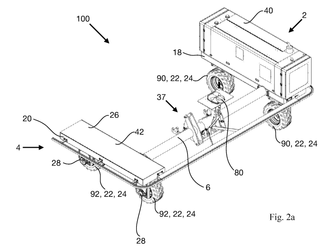
Fig. 2a is a perspective view of an agricultural work vehicle 100 according to
the present
invention. The work vehicle 100 comprising a first drive module 2 and a second
drive module
4. Each drive module comprises two drive means 90,92 in the form of wheels 24.
CA 03118019 2021-04-28
WO 2020/108713 PCT/D1(2019/050355
17
Again, it is seen that the first drive module 2 is connected to the second
drive module 4 by a
connecting element 6. The connecting element 6 carries coupling means 37 in
the form of a
three-point hiss for coupling an agricultural implement to the vehicle.
The inventive work vehicle 100 is provided with a load carrying platform 26 at
the second
drive module 4. The load carrying module 26 is integrated with the chassis 20
of the second
drive module and it comprises an upper surface 42. It is seen that the load
carrying platform
26 is arranged above the wheels 24 of the second drive module 4.
As it will be revealed in Fig. 2e most of the technology necessary to propel
and operate the
inventive work vehicle 100 illustrated in Fig. 2a is located under the cover
40 of the first drive
module 2.
Fig. 2b is a top view illustrating the agricultural work vehicle shown in Fig.
2a and Fig. 2c is a
front view thereof. Fig. 2b points out that a free space 38 is provided
between the first drive
module 2 and the second drive module 4. Fig. 2b and 2c show that the
connecting element 6
comprises a first axial end 8 and a second axial end 10.
Fig. 2c shows that the two front wheels 24 of the drive means 90,92 are
suspended in a wheel
base 33, each of which allows the alternation of the pitch of the rotational
plane of each
wheel, relative to a fixed geographical direction.
Fig. 2d is a side view of the inventive agricultural work vehicle illustrated
in Fig. 2a as seen
from the right side, relative to the second drive module 4.
Fig. 2e is a perspective view illustrating the inventive agricultural work
vehicle of Fig. 2a
with the cover 40 of the first drive module 2 removed, thereby exposing
details of the
mechanics and hydraulics involved in the operation of the vehicle.
Fig. 2e shows that only drive unit 2 comprises a diesel engine 102 for
providing power for
propelling the work vehicle. A hydraulic pump 30 is integrated with the
engine. Associated
herewith are also provided a diesel tank 106 and a battery 104.
Hydraulic valves 35 controls the actuation of hydraulic actuation means 34 for
steering the
work vehicle. A control unit 16 is also seen in Fig. 2e.
Although the first drive module 2 comprises most of the equipment for
providing power to
and for operating the inventive work vehicle100, hydraulic hoses are provided
to the
CA 03118019 2021-04-28
WO 2020/108713 PCT/D1(2019/050355
18
hydraulic drive 28 and to the actuator 34 for controlling the wheel base 33 in
respect of both
drive modules (not seen in Fig. 2e).
By concentrating most of the equipment necessary to operate the work vehicle
100 at the first
drive module 2 it is possible to provide adequate space at the second drive
module 4 allowing
providing this module 4 with the load carrying platform 26, while still
providing full
operational control of the first drive module 2 as well as the second drive
module 4.
Fig. 3 is a diagrammatic illustration illustrating the working mode of the
control unit of the
agricultural working unit of the present invention.
Fig. 3 shows that control unit 16 which is being connected to an input means
82. The input
means allows for programming or setting the desired operation of the
agricultural work
vehicle 100. A display 84 allows for monitoring the setting and the
operational state of the
agricultural work vehicle. Alternative to the input means 82 the control unit
may also be
programmed or may receive information relating to desired settings by means of
the receiver
86 for receiving electromagnetic signals.
Fig. 3 also shows that the control unit is coupled to a position indicating
receiver 80 which is
configured for providing to the control unit information relating to a current
geographical
position of the agricultural work vehicle 100. A data storage 76 is provided
for storing data
relating to the operation of the agricultural vehicle, such as data relating
to geographical
coordinates of a desired trajectory to be followed during working of an
agricultural field.
A switch 78 is provided for allowing switching the operational mode between an
autonomous
working mode, a manually controlled working mode, such as a remotely
controlled mode or a
semi-autonomous working mode. The switch 78 may also be actuated wirelessly by
means of
the receiver 86.
The control unit 16 is configured for providing signals to the propulsion
means 12 relating to
controlling the propulsion of the vehicle.
Moreover, the control unit 16 is configured for providing signals to a
hydraulic valve 35
which in turn provides for supplying hydraulic fluid to the hydraulic actuator
34 which is
responsible for actuating the wheel bases 33 so as to turn these with the view
to steer the
agricultural work vehicle.
CA 03118019 2021-04-28
WO 2020/108713 PCT/D1(2019/050355
19
Accordingly, in an autonomous working mode, the control unit has been
supplied, via the
input means 82 or the receiver 86, with information relating to a desired
trajectory to be
followed by the working vehicle when working an agricultural field. The
position indicating
means 80 will constant provide information to the control unit relating to the
geographical
position of the work vehicle. Based on this information and based on the
desired trajectory to
be followed, the control unit will constantly provide propulsion information
and steering
information, respectively, to the propulsion means 12 and to the hydraulic
valve 35,
respectively, with the view to safely and efficiently make the agricultural
work vehicle follow
a desired path on the agricultural field during working thereof.
It should be understood that all features and achievements discussed above and
in the
appended claims in relation to one aspect of the present invention and
embodiments thereof
apply equally well to the other aspects of the present invention and
embodiments thereof.
CA 03118019 2021-04-28
WO 2020/108713
PCT/D1(2019/050355
List of reference numerals
2 First drive module
4 Second drive module
6 Connecting element
5 8 First axial end of connecting element
10 Second axial end of connecting element
12 Propulsion means
14 Steering means
16 Control unit
10 18 First chassis
20 Second chassis
22 Set of wheels
24 Wheel
26 Load carrying platform
15 28 Hydraulic drive
Hydraulic pump
32 Motor for driving hydraulic pump
33 Wheel base
34 Actuation means of steering means
20 35 Hydraulic valve
36 Energy storage or energy provider
37 Coupling means
38 Free space
CA 03118019 2021-04-28
WO 2020/108713
PCT/D1(2019/050355
21
40 Cover of drive module
42 Upper surface of load carrying platform
76 Data storage
78 Switching means
80 Position indicating means
82 Input means
84 Display
86 Receiver for electromagnetic signals
90, 92 Drive means
100 Agricultural work vehicle according to the invention
102 Diesel engine
104 Battery
106 Diesel tank
300 Prior art agricultural work vehicle
CA 03118019 2021-04-28
WO 2020/108713 PCT/D1(2019/050355
22
The invention of the present patent application may be defined according to
the
following clause 1 - 50:
Clause 1: An agricultural work vehicle (100) for performing an agricultural
work operation in
an agricultural field, wherein said work vehicle comprises:
-a first drive module (2);
-a second drive module (4);
-a connecting element (6); said connecting element comprises a first axial end
(8) and a second axial end (10);
-propulsion means (12) for propelling said work vehicle;
-steering means (14) for steering said work vehicle;
-a control unit (16) for controlling the operation of said work vehicle;
wherein said first drive module (2) comprises a first chassis (18);
wherein said second drive module (4) comprises a second chassis (20);
wherein said first drive module (2) comprises drive means (90) for allowing
said first drive
module to move over ground, said drive means (90) being suspended on said
first chassis
(18);
wherein said second drive module comprises drive means (92) for allowing said
second drive
module to move over ground, said drive means (92) being suspended on said
second chassis
(20);
wherein said first axial end (8) of said connecting element (6) is being
attached to said first
chassis (18); and wherein said second axial end (10) of said connecting
element (6) is being
connected to said second chassis (20);
wherein one of said two drive modules (2,4) comprises a load carrying platform
(26) arranged
at the corresponding chassis (18,20).
Clause 2: An agricultural work vehicle (100) according to clause 1, wherein
said agricultural
work vehicle is being a remotely controlled work vehicle and/or an autonomous
work vehicle
and/or a semi-autonomous work vehicle.
CA 03118019 2021-04-28
WO 2020/108713 PCT/D1(2019/050355
23
Clause 3: An agricultural work vehicle (100) according to clause 1 or 2,
wherein said
propulsion means (12) comprises one or more electric motors or one or more
hydraulic drives
(28) or one or more mechanical drives for driving said drive means (90,92).
Clause 4: An agricultural work vehicle (100) according to any of the preceding
clauses,
wherein said drive means (90,92) each comprises two or more sets of wheels,
wherein all
wheels in a specific set of wheels are sharing a common axis of rotation;
and/or wherein said
drive means (90,92) comprises one or two or more caterpillar belts.
Clause 5: An agricultural work vehicle (100) according to clause 4, wherein
said drive means
(90,92) each comprises two sets (22) of wheels (24), said sets (22) of wheels
(24) being
arranged behind each other, as seen relative to a non-turning direction of
movement of said
vehicle.
Clause 6: An agricultural work vehicle (100) according to clause 5, wherein in
respect of a
specific set (22) of wheels (24), said set of wheel comprises one, two, three,
or four or more
wheels (24).
Clause 7: An agricultural work vehicle (100) according to clause 4, wherein
said drive means
(90,92) comprises one, two, three, or four or more caterpillar belts,
optionally being arranged
sideways to each other and/or behind each other.
Clause 8: An agricultural work vehicle (100) according to any of the clauses 5
- 7, wherein
said propulsion means are configured for driving one or two sets (22) of
wheels (24) or
caterpillar belts of each drive module (2,4).
Clause 9: An agricultural work vehicle (100) according to any of the clauses 1
¨ 8, wherein
said propulsion means (12) comprises hydraulic drives for driving said drive
means (90,92)
and wherein said agricultural work vehicle comprises one or more hydraulic
pumps (30) for
driving said hydraulic drives (28), wherein said agricultural work vehicle
furthermore
comprises a motor (32) for driving said hydraulic pump (30), such as an
electric motor; or a
combustion engine, such as a petrol engine or a diesel engine, or a biogas
engine.
Clause 10: An agricultural work vehicle (100) according to any of the clauses
1 ¨ 8, wherein
said propulsion means (12) comprises an electric motor for driving said drive
means (90,92).
Clause 11: An agricultural work vehicle (100) according to any of the clauses
1 ¨ 8, wherein
said propulsion means (12) comprises mechanical means for driving said drive
means (90,92).
CA 03118019 2021-04-28
WO 2020/108713 PCT/D1(2019/050355
24
Clause 12: An agricultural work vehicle (100) according to any of the
preceding clauses,
wherein one or more of said wheels (24) independently is/are having an outer
diameter of 25
¨ 300 cm, such as 30 ¨ 275 cm, for example 35 ¨ 250 cm, such as 40 ¨ 225 cm,
e.g. 45 ¨ 200
cm, such as 50 ¨ 175 cm, e.g. 55 ¨ 150 cm, such as 60 ¨ 125 cm, e.g. 65 ¨ 100
cm, such as 70
- 95 cm, such as 75 ¨ 90 cm, e.g. 80 ¨ 85 cm.
Clause 13: An agricultural work vehicle (100) according to any of the
preceding clauses
wherein at least one set (22) of wheels (24) of each drive module (2,4) is
being pivotally
suspended in a wheel base (34) on its corresponding chassis (18,20) in such a
way that the
pitch of the rotational plane of said one or more wheels (24) of said set (22)
of wheels can be
altered, relative to a fixed geographical direction, and wherein said steering
means (14)
comprises actuation means (34) for altering said pitch.
Clause 14: An agricultural work vehicle (100) according to any of the
preceding clauses,
wherein said steering means (14) comprises means for allowing propelled wheels
(24) of one
drive module (2,4) to rotate at a rotational speed which is different from the
rotational speed
of the propelled wheels (24) of the other drive module (4,2).
Clause 15: An agricultural work vehicle (100) according to any of the
preceding clauses,
wherein the shortest distance from the center of a wheel (24) of one drive
module (2,4) to the
center of a wheel (24) of the other drive module (4,2) is selected from the
range 20 - 4000 cm,
such as 30 ¨ 3500 cm, e.g. 40 ¨ 3000 cm, such as 50 ¨ 2500 cm, for example 60
¨ 2000 cm,
e.g. 70 ¨ 1800 cm, such as 80 ¨ 1700 cm, e.g. 90 ¨ 1600 cm, for example 100 ¨
1500 cm, e.g.
150 ¨ 1400 cm, e.g. 200 ¨ 1300 cm, such as 250 ¨ 1200 cm, such as 300 ¨ 1100
cm, such as
350 ¨ 1000 cm, such as 400 ¨ 900 cm, such as 500 ¨ 800 cm, e.g. 600 ¨ 700 cm.
Clause 16. An agricultural work vehicle (100) according to any of the
preceding clauses
comprising an energy storage or energy provider (36), such as a fuel tank or a
battery; or one
or more solar panels; or one or more fuel cell modules in combination with a
fuel gas tank,
such as a hydrogen tank or a methane tank.
Clause 17: An agricultural work vehicle (100) according to any of the
preceding clauses
further comprising coupling means (38) for allowing coupling to said
agricultural work
vehicle of an agricultural implement, said coupling means (37) optionally
being arranged at or
on said connecting element (6), said coupling means optionally being in the
form of a three-
point hitch or in the form of an A frame.
CA 03118019 2021-04-28
WO 2020/108713 PCT/D1(2019/050355
Clause 18: An agricultural work vehicle (100) according to any of the
preceding clauses,
wherein said first drive module (2) and said second drive module (4) are
having an elongate
shape.
Clause 19: An agricultural work vehicle (100) according to any of the
preceding clauses,
5 wherein said first axial end (8) of said connecting element (6) is
attached to said first chassis
(18) of said first drive module (2) at an end thereof; and wherein said second
axial end (10) of
said connecting element (6) is attached to said second chassis (20) of said
second drive
module (4) at an end thereof.
Clause 20: An agricultural work vehicle (100) according to any of the
preceding clauses,
10 wherein said first drive module (2) and said second drive module (4) are
arranged essentially
in a parallel orientation relative to each other.
Clause 21: An agricultural work vehicle (100) according to any of the
preceding clauses,
wherein said first drive module (2) and said second drive module (4) are
arranged relative to
each other in such a way that a free space (38) is being present between part
of said first drive
15 module (2) and part of said second drive module (4).
Clause 22: An agricultural work vehicle (100) according to clause 21, wherein
the free space
(38) between the first drive module (2) and the second drive module (4) in a
region appearing
in a direction perpendicular to the connecting element (6), such as in a
forward pointing
direction and/or in a rearward pointing direction, is devoid from any element
connecting said
20 first drive module (2) to said second drive module (4).
Clause 23: An agricultural work vehicle (100) according to any of the
preceding clauses
wherein each drive means (90,92) is being rigidly suspended at or on its
corresponding
chassis (18,20), i.e. in a non-spring-loaded manner.
Clause 24: An agricultural work vehicle (100) according to any of the
preceding clauses
25 wherein said work vehicle comprises a monitoring unit for visually
monitoring soil and/or
vegetation during operation thereof.
Clause 25: An agricultural work vehicle (100) according to any of the
preceding clauses
wherein said work vehicle comprises means for allowing, during driving a
curved trajectory,
the outer drive means, such as the outer wheels, to rotate a higher angular
velocity, compared
to the inner drive means, such as the inner wheels.
CA 03118019 2021-04-28
WO 2020/108713 PCT/D1(2019/050355
26
Clause 26: An agricultural work vehicle (100) according to any of the
preceding clauses
wherein the part of the propulsion means (12) providing the power for
propelling said
agricultural work vehicle is being solely arranged on said first drive module
(2).
Clause 27: An agricultural work vehicle (100) according to any of the
preceding clauses
wherein said control unit (16) is being solely arranged at said first drive
module (2).
Clause 28: An agricultural work vehicle (100) according to any of the
preceding clauses,
wherein any energy storage or energy provider (36), such as a fuel tank or a
battery; or one or
more solar panels; or one or more fuel cell modules in combination with a fuel
gas tank, such
as a hydrogen tank or a methane tank, is/are being solely arranged at said
first drive module
.. (2).
Clause 29: An agricultural work vehicle (100) according to any of the
preceding clauses,
wherein said load carrying platform (26) defines an upper surface (42) having
an extension in
a longitudinal direction of 100 ¨ 4000 cm, such as 150 ¨ 3500 cm, e.g. 200 ¨
3000 cm, for
example 250 ¨ 2500 cm, such as 300 ¨ 2000 cm, e.g. 400 ¨ 1500 cm, e.g. 500 ¨
1000 cm.
Clause 30: An agricultural work vehicle (100) according to any of the
preceding clauses,
wherein said load carrying platform (26) defines an upper surface (42) having
an extension in
a transverse direction of 25 ¨ 1500 cm, such as 50 ¨ 1200 cm, e.g. 100 ¨ 1000
cm, such as
150 ¨ 800 cm, e.g. 200 ¨ 700 cm, such as 300 ¨ 600 cm or 400 ¨ 500 cm.
Clause 31: An agricultural work vehicle (100) according to any of the
preceding clauses,
wherein said load carrying platform (26) defines an upper surface (42) which
is being
arranged at a level above ground of 20 ¨ 200 cm, such as 25 ¨ 175 cm, e.g. 50
¨ 150 cm, such
as 75 ¨ 125 cm.
Clause 32: An agricultural work vehicle (100) according to any of the
preceding clauses,
wherein said load carrying platform (26) is being arranged at a level above
said drive means
(92) of said second drive module (4).
Clause 33: An agricultural work vehicle (100) according to any of the
preceding clauses,
wherein said load carrying platform (26) is being arranged above said second
chassis (20) of
the second drive module (4); or wherein said load carrying platform (26) is
integrated with
said second chassis (20) of said second drive module (4).
CA 03118019 2021-04-28
WO 2020/108713 PCT/D1(2019/050355
27
Clause 34: An agricultural work vehicle (100) according to any of the
preceding clauses,
wherein said load carrying platform (26) defines an upper surface (42) having
a rectangular
shape.
Clause 35: An agricultural work vehicle (100) according to any of the
preceding clauses,
wherein said load carrying platform (26) comprises one or more essentially
vertical sides,
such as detachable sides, for securing goods being arranged on said platform.
Clause 36: An agricultural work vehicle (100) according to any of the
preceding clauses,
wherein the second drive module (4) is devoid of any of the following: part of
the propulsion
means (12) providing the power for propelling said agricultural work vehicle;
said control unit
(16); any energy storage or energy provider (36), such as a fuel tank or a
battery; or one or
more solar panels; or one or more fuel cell modules in combination with a fuel
gas tank, such
as a hydrogen tank or a methane tank.
Clause 37: An agricultural work vehicle (100) according to any of the
preceding clauses,
wherein said upper surface (42) of said load carrying platform (26) is being
essentially planer.
Clause 38: An agricultural work vehicle (100) according to any of the
preceding clauses,
wherein said upper surface (42) of said load carrying platform (26) is being
essentially
horizontally arranged at said drive module (2,4).
Clause 39: An agricultural work vehicle (100) according to any of the
preceding clauses
further comprising an agricultural implement for performing an agricultural
work operation.
Clause 40: An agricultural work vehicle (100) according to clause 39, wherein
said
agricultural implement is being selected from the group comprising: a tillage
implement, a
harrow, a seed drill, a cultivator, a weeder, a sprayer, a spreader, an
irrigator, a harvesting
implement.
Clause 41: An agricultural work vehicle (100) according to any of the
preceding clauses
further comprising a monitoring unit for monitoring the operation of said work
vehicle.
Clause 42: An agricultural work vehicle (100) according to any of the
preceding clauses
wherein said control unit (16) is being configured for receiving and storing
information on a
data storage (76), relating to one or more of the following: geographic
coordinates relating to
the boundary of an agricultural field to be worked; geographic coordinates
relating to the
boundary of one or more obstacles being present in an agricultural field to be
worked;
CA 03118019 2021-04-28
WO 2020/108713 PCT/D1(2019/050355
28
geographic coordinates relating to a preferred trajectory to be followed by
said agricultural
work vehicle; information relating to the effective working width of an
agricultural implement
to be carried/towed by said agricultural implement.
Clause 43: An agricultural work vehicle (100) according to any of the
preceding clauses,
.. wherein said control unit (16) comprises switching means (78) for allowing
an operator to
switch between an autonomous working mode and/or a remotely controlled working
mode
and/or a semi-autonomous working mode of said agricultural work vehicle (100).
Clause 44: An agricultural work vehicle (100) according to any of the
preceding clauses,
wherein said agricultural work vehicle comprises position indicating means
(80), such as a
GNSS (Global Navigation Satellite System) receiver, such as a GPS receiver for
providing
information relating to a geographical position of said vehicle.
Clause 45: An agricultural work vehicle (100) according to clause 44, wherein
said control
unit (16) is configured to receive information from said position indicating
means (80),
relating to said geographical position of said work vehicle.
Clause 46: An agricultural work vehicle (100) according to any of the clauses
42 ¨ 45,
wherein said control unit (16) is being configured to provide instructions to
said propulsion
means (12) and to said steering means (14) of said work vehicle so as to make
said work
vehicle follow a desired trajectory on said agricultural field; wherein
geographical coordinates
of said desired trajectory is being or has been provided to said control unit
(16).
.. Clause 47: An agricultural work vehicle (100) according to any of the
preceding clauses
wherein said agricultural work vehicle comprises input means (82) for
programming said
control unit (16), such as in the form of a receiver for wirelessly receiving
information
relating to a programming of said control unit.
Clause 48: An agricultural work vehicle (100) according to any of the
preceding clauses
.. wherein said agricultural work vehicle comprises a display (84), such as a
monitor for
displaying information relating to an operational state of said agricultural
vehicle.
Clause 49: Use of an agricultural work vehicle (100) according to any of
preceding clauses for
performing an agricultural work operation.
Clause 50: Use according to clause 49, wherein said agricultural work
operation is being
.. selected from the group comprising: surveying of the agricultural field,
tillaging soil,
CA 03118019 2021-04-28
WO 2020/108713 PCT/D1(2019/050355
29
harrowing soil, seeding seeds into soil, cultivation of soil, weeding of soil,
spraying, such as
spraying of a herbicide or of a pesticide or of a fungicide, spreading of
fertilizer, irrigation of
the field with water, harvesting crops.