Note: Descriptions are shown in the official language in which they were submitted.
DECORATIVE BUTTON COVER SYSTEM
BACKGROUND
[0001] Buttons are often used to fasten together pieces of fabric or
portions of a single fabric
garment. Different types of buttons exist (e.g., for different types or styles
of garment, for different
types of fashion), but a user may tire of the particular button or buttons
installed on a particular
garment. That is, a user may desire to exchange one or more of the existing
buttons on a garment
for buttons of a different style, color, or other aesthetic characteristic. In
some cases, the user may
desire to exchange the existing button(s) only temporarily to, for example,
coincide with a
particular outfit. Changing or replacing buttons, however, can be cumbersome,
tedious, and time-
consuming. Further, changing or replacing buttons can require some amount of
sewing ability that
a given user may not possess.
100021 Accordingly, there is a need for easily exchangeable button
aesthetics, while
minimizing or eliminating the technical ability required to exchange the
button aesthetic.
SUMMARY
[0003] These and other problems may be addressed by the technology
disclosed herein. The
disclosed technology includes a decorative button cover system. The decorative
button cover
system can include a button slide portion configured to slidably receive at
least a portion of an
existing button of a garment, and the decorative button cover system can
include a decorative
portion attached to the button slide portion. The decorative button cover
system can also include a
button of a garment configured to at least partially insert into a button
slide. For example, the
decorative button cover system can include one or more buttons (e.g., modified
jeans buttons,
modified blazer buttons) configured to insert into, and be snugly received by,
a corresponding
button slide.
[0004] The disclosed technology includes a decorative button system that
can include a button
slider configured to slidably receive at least a portion of a button. The
button slider can include a
slot and a channel. The slot can be configured to receive at least a portion
of the button, and the
slot can include comprising an upper surface and a lower lip. At least one of
the upper surface or
the lower lip can include a protrusion that is configured to abut a surface of
the button. The channel
1
Date Recue/Date Received 2021-05-12
can extend radially inward from an outer edge of the button slider. The
channel can be (i) in direct
communication with the slot, and the channel can be configured to permit an
attachment portion
of the button to pass therethrough.
[0005] The slot of the button slider can be substantially parallel to a top
surface of the button
slider.
100061 The decorative button system can include a decorative portion
attached to a top surface
of the button slider.
[0007] The slot can include one or more sloped walls located at a perimeter
of the slot.
100081 The one or more sloped walls can include (i) a first upper sloped
wall portion extending
between an upper surface of the slot and a first inner side wall portion of
the slot, (ii) a first lower
sloped wall portion extending between a lower lip of the slot and the first
inner side wall portion
of the slot, (iii) a second upper sloped wall portion extending between the
upper surface of the slot
and a second inner side wall portion of the slot, the second inner side wall
portion being generally
opposite the first inner side wall portion, and (iv) a second lower sloped
wall portion extending
between the lower lip of the slot and the second inner side wall portion of
the slot. One, some, or
all of the first inner side wall portion, the first upper sloped wall portion,
the first lower sloped
wall portion, the second inner side wall portion, the second upper sloped wall
portion, and the
second lower sloped wall portion can be curved.
[0009] The one or more sloped walls can include (i) a third upper sloped
wall portion extending
between the upper surface of the slot and a rear inner wall portion of the
slot and (ii) a third lower
sloped wall portion extending between the lower lip of the slot and the rear
inner wall portion of
the slot. One, some, or all of the rear inner wall portion, the third upper
sloped wall portion, and
the third upper sloped wall portion can be curved.
[0010] The decorative button system can include a button structure that can
include a post and
a flange portion. The post can have a first end and a second end. The flange
portion can be
connected to the second end of the post. The flange portion can include a slot
that can be configured
to at least partially receive the button slider.
[0011] The flange portion of the button structure can include an attachment
portion configured
to connect to the first end of the post of the button structure. The
attachment portion can comprise
a rivet or a threaded portion. The attachment portion can have a surface
configured to abut a first
side of a material, and the first end of the post is configured to abut a
second side of the material
2
Date Recue/Date Received 2021-05-12
such that, when the attachment portion is connected to the first end of the
post, the button structure
is attached to the material.
[0012] The button structure can include an attachment protrusion located at
least partially
within the slot of the flange portion. The attachment protrusion can include a
stem and a disc
portion. The stem can be configured to slideably insert into at least
partially the channel of the
button slider, and the disc portion can be configured to slideably insert into
at least partially the
slot of the button slider. At least one of the stem or the disc portion can be
connected to a rear wall
of the slot of the flange portion.
100131 The disclosed technology includes a decorative button kit that can
include a button
structure, a first decorative button system, and/or a second decorative button
system. The button
structure can include a post and a flange portion. The post can have a first
end and a second end,
and the flange portion can be connected to the second end of the post. The
flange portion can
include a flange slot. The button structure can include an attachment
protrusion that can be located
at least partially within the flange slot. The attachment protrusion can
include a stem and a disc
portion. The stem can have a first end attached to a bottom surface of the
flange slot and a second
end. The disc portion can be attached to the second end of the stem. The first
decorative button
system can include a first button slider and a first decorative portion
attached to a top surface of
the first button slider. The first button slider can be configured to slidably
receive at least a portion
of the button structure. The first button slider can include a first slot and
a first channel. The first
slot can be configured to receive at least the portion of the disc portion of
the attachment protrusion.
The first slot can include an upper surface and a lower lip, and at least one
of the upper surface or
first lower lip can include a protrusion configured to abut a surface of the
disc portion of the
attachment protrusion. The first channel can extend radially inward from an
outer edge of the first
button slider. The first channel can be in direct communication with the first
slot and can be
configured to permit the stem of the attachment protrusion to pass
therethrough. The second
decorative button system can include a second button slider and a second
decorative portion
attached to a top surface of the second button slider. The second decorative
portion can have a
decorative effect that is different from a decorative effect of the first
decorative portion of the first
decorative button system. The second button slider can be configured to
slidably receive at least a
portion of the button structure. The second button slider can include a second
slot and a second
channel. The second slot can be configured to receive at least the portion of
the disc portion of the
3
Date Recue/Date Received 2021-05-12
attachment protrusion. The second slot can include an upper surface and a
lower lip, and at least
one of the upper surface or second lower lip can include a protrusion
configured to abut a surface
of the disc portion of the attachment protrusion. The second channel can
extend radially inward
from an outer edge of the second button slider. The second channel can be in
direct communication
with the second slot and can be configured to permit the stem of the
attachment protrusion to pass
therethrough.
[0014] The flange slot can be configured to at least partially receive the
first button slider or
the second button slider.
100151 At least one of the stem of the attachment protrusion or the disc
portion of the
attachment protrusion can be connected to a rear wall of the flange slot of
the flange portion.
[0016] The button structure can include an attachment portion configured to
connect to the
first end of the post. The attachment portion can include a rivet or a
threaded portion.
100171 These and other aspects of the present disclosure are described in
the Detailed
Description below and the accompanying figures. Other aspects and features of
the present
disclosure will become apparent to those of ordinary skill in the art upon
reviewing the following
description of specific examples of the present disclosure in concert with the
figures. While
features of the present disclosure may be discussed relative to certain
examples and figures, all
examples of the present disclosure can include one or more of the features
discussed herein.
Further, while one or more examples may be discussed as having certain
advantageous features,
one or more of such features may also be used with the various other examples
of the disclosure
discussed herein. In similar fashion, while examples may be discussed below as
devices, systems,
or methods, it is to be understood that such examples can be implemented in
various devices,
systems, and methods of the present disclosure.
BRIEF DESCRIPTION OF THE FIGURES
100181 Reference will now be made to the accompanying figures, which are
not necessarily
drawn to scale, and wherein:
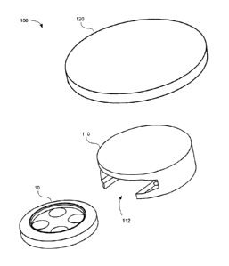
[0019] FIG. 1 illustrates an exploded view of a decorative button system
and a button, in
accordance with the disclosed technology;
100201 FIG. 2A illustrates a top view of a button slide portion of an
example decorative button
system, in accordance with the disclosed technology;
4
Date Recue/Date Received 2021-05-12
[0021] FIG. 2B illustrates a side view of a button slide portion of an
example decorative button
system, in accordance with the disclosed technology;
[0022] FIG. 2C illustrates a side view of a button slide portion of an
example decorative button
system, in accordance with the disclosed technology;
100231 FIG. 2D illustrates a cross-sectional view taken along line D-D of
FIG. 2A, in
accordance with the disclosed technology;
[0024] FIG. 2E illustrates a cross-sectional view taken along line E-E of
FIG. 2B, in
accordance with the disclosed technology;
100251 FIG. 2F illustrates a cross-sectional view taken along line F-F of
FIG. 2B, in accordance
with the disclosed technology;
[0026] FIG. 3A illustrates a bottom view of a button slide portion of an
example decorative
button system with a button disposed substantially therein, in accordance with
the disclosed
technology;
100271 FIG. 3B illustrates a side view of a button slide portion of an
example decorative button
system with a button disposed substantially therein, in accordance with the
disclosed technology;
[0028] FIG. 4A illustrates a first perspective view of an example button
slide, in accordance
with the disclosed technology;
100291 FIG. 4B illustrates a second perspective view of an example button
slide, in accordance
with the disclosed technology;
[0030] FIG. 5A illustrates an example button structure and an example
button slide portion of
an example decorative button system, in accordance with the disclosed
technology; and
100311 FIGs. 5B-5E illustrate a front view, a top view, a side view, and a
rear view,
respectively, of the example button structure shown in FIG. 5A.
DETAILED DESCRIPTION
100321 Throughout this disclosure, certain examples are described in
relation to decorative
button covers. Examples of the disclosed technology can be used in conjunction
with any type of
button. That is, the disclosed decorative button covers can be sized and
configured to receive
buttons of a particular size, shape, and/or design. For example, the disclosed
decorative button
covers can be used with buttons of shirts, blouses, pants (e.g., slacks,
jeans), blazers, jackets, coats,
or any other garment or other item including one or more buttons.
Date Recue/Date Received 2021-05-12
[0033] The disclosed technology will be described more fully hereinafter
with reference to the
accompanying drawings. This disclosed technology may, however, be embodied in
many different
forms and should not be construed as limited to the embodiments set forth
herein. The components
described hereinafter as making up various elements of the disclosed
technology are intended to
be illustrative and not restrictive. Many suitable components that would
perform the same or
similar functions as components described herein are intended to be embraced
within the scope of
the disclosed technology. Such other components not described herein may
include, but are not
limited to, for example, components developed after development of the
disclosed technology.
100341 In the following description, numerous specific details are set
forth. But it is to be
understood that embodiments of the disclosed technology may be practiced
without these specific
details. In other instances, well-known methods, structures, and techniques
have not been shown
in detail in order not to obscure an understanding of this description.
References to "one example,"
"an example," "some examples," "certain examples," "various examples," "one
embodiment," "an
embodiment," "example embodiment," "some embodiments," "certain embodiments,"
"various
embodiments," etc., indicate that the example(s) and/or embodiment(s) of the
disclosed technology
so described can include a particular feature, structure, or characteristic,
but not every example
and/or embodiment necessarily includes the particular feature, structure, or
characteristic. Further,
repeated use of the phrase "in one example" or "in one embodiment" does not
necessarily refer to
the same embodiment, although it may.
[0035] Throughout the specification and the claims, the following terms
take at least the
meanings explicitly associated herein, unless the context clearly dictates
otherwise. The term "or"
is intended to mean an inclusive "or." Further, the terms "a," "an," and "the"
are intended to mean
one or more unless specified otherwise or clear from the context to be
directed to a singular form.
[0036] Unless otherwise specified, any use of the ordinal adjectives
"first," "second," "third,"
etc., to describe a common object, merely indicate that different instances of
like objects are being
referred to, and are not intended to imply that the objects so described
should be in a given
sequence, either temporally, spatially, in ranking, or in any other manner.
[0037] As explained above, the disclosed technology relates to decorative
button cover
systems. Referring to FIG. 1, a decorative button cover system 100 can include
a button slide
portion 110 and a decorative portion 120. The button slide portion 110 can be
configured to attach
to a button 10, and the decorative portion 120 can comprise a particular color
or aesthetic design.
6
Date Recue/Date Received 2021-05-12
The button slide portion 110 can include a slot 112 that is configured to
receive at least a portion
of a button 10. The slot 112 of the button slide portion 110 (also referred to
herein as "button slider
110") can be sized and/or dimensioned to clasp onto the button 10 such that
the button slide portion
is removably attached onto the button 10. The decorative portion 120 can be
attached to the button
slide portion 110. The decorative portion 120 can be attached to the button
slide portion 110
permanently. Alternatively, the decorative portion 120 can be attached to the
button slide portion
temporarily (e.g., removeably). The decorative portion 120 can be attached to
the button slide
portion 110 via an adhesive (e.g., glue, epoxy), adhesive tape, a hook-and-
loop fastener, a threaded
connector, other fasteners, soldering, brazing, welding, or any other
attachment, connector, or
fastener or related method. Alternatively, the decorative button cover system
100 can omit the
decorative portion, and an upper portion and/or surface of the button slider
110 can be decorated,
as a non-limiting example.
100381 Although the button slider 110 and the decorative portion 120 are
illustrated as being
generally disk-like in shape, the disclosed technology is not so limited. That
is, the button slider
110 and/or the decorative portion 120 can have any shape. For example, the
button slider 110
and/or the decorative portion can have a cross-sectional shape that is a
triangle, a square, a
rectangle, a trapezoid, a pentagon, a hexagon, an octagon, any other polygonal
shape, or any
geometrically abnormal shape. Further, although the decorative portion 120 is
illustrated as having
a generally flat top surface, the decorative portion 120 can have any shape.
For example, the
decorative portion 120 can have a three-dimensional shape, which can include,
but is not limited
to, a hemispherical shape, a conical shape, or the like.
100391 The button slider 110 can comprise any useful material. For example,
the button slider
110 can comprise one or more plastics (e.g., nylon, polyethylene (PE),
polypropylene (PP),
polyethylene terephthalate (PET), polyvinyl chloride (PVC), acrylonitrile-
butadiene-styrene
(ABS)) and/or one or more metals (e.g., aluminum, copper, steel) or alloys
thereof Similarly, the
decorative portion 120 can comprise one or more plastics, (e.g., nylon, PE,
PP, PET, PVC, ABS),
one or more metals (e.g., aluminum, copper, steel) or alloys thereof, wood,
stone, gems, ceramic,
glass, fabric, any other useful material(s), or any combination thereof The
decorative portion 120
can include decorations or aesthetics elements that can be provided via paint,
dyes, enamel,
lacquer, wood, stone, gems, ceramic, glass, fabric, one or more metals and/or
alloys, one or more
plastics, or the like.
7
Date Recue/Date Received 2021-05-12
[0040] Referring particularly to FIGs. 2A-2F, 4A, and 4B, the button slider
110 is described
in more detail. The button slider 110 can include a slot 112 that is
substantially parallel to a top
face of the button slider 110. The slot 112 can be dimensioned to be receive
at least a portion of a
corresponding button 10. The slot 112 can include an upper surface 214 and a
lower lip 216 such
that, as a button 10 is slidably inserted into the slot 112, the lower lip 216
is positioned under a
bottom surface of the button. Thus, the button 10 can be substantially
contained within the slot 112
of the button slider 110.
[0041] The button slider 110 can include a thread channel 218 that is in
communication with
the slot 112, and the thread channel 218 can receive the attachment portion
(e.g., attachment
threads, post and rivet, threaded post and bolt) that extend between the
button 10 and the respective
garment or other item (thereby connecting the button 10 to the item). By so
doing, the thread
channel 218 can help facilitate insertion of the button 10 into the button
slider 110. As will be
appreciated by one of ordinary skill in the art, the thread channel 218 can be
sized and/or
dimensioned to receive a particular type of button. For example, the button
slider 110 can be
configured to receive a button attached to the garment via a post assembly, as
is commonly found
on jeans or other denim garments. That is, some button sliders 110 can have a
comparatively small
or narrow thread channel 218 configured to receive buttons attached via
attachment threads,
whereas other button sliders 110 can have a comparatively large or wide thread
channel 218 that
are configured to receive buttons attached via a post and some other
attachment mechanism, such
as a rivet, a screw, or the like.
100421 The button slider 110 can include one or more protrusions 220. The
protrusions 220
can be configured to abut the button 10 when the button 10 is inserted into
the slot 112, and the
protrusions 220 can provide frictional resistance (e.g., between the
protrusion 220 and the button
10, between the button 10 and the upper surface 214 and/or the lower lip 216)
to prevent the button
from freely sliding out of the button slider 110. Although the drawings depict
protrusions 220
as protruding from the lower lip 216, the disclosed technology is not so
limited. Alternatively or
in addition, one or more protrusions 220 can extend from the upper surface
214. Depending on the
placement of the protrusion(s) 220, the protrusion(s) 220 can abut a top
surface of the button 10
and/or a bottom surface of the button 10 when the button 10 is inserted into
the slot 112.
100431 The button slider 110 can include one or more sloped walls 222. The
sloped walls 222
can be disposed about some or all of the outer perimeter of the slot 112. That
is, one or more sloped
8
Date Recue/Date Received 2021-05-12
walls 222 can extend between the lower lip 216 and an inner side wall, and/or
one or more sloped
walls 22 can extend between the upper surface 214 and an inner side wall. The
sloped walls 222
can provide additional contact points between the button 10 and the button
slider 110 to provide
frictional resistance, which can help prevent the button 10 from freely
sliding out of the button
slider 110.
100441 The disclosed technology can include a set of multiple button cover
systems 100. For
example, a set can include a plurality of button cover systems 100, with each
button cover system
100 providing a different design or aesthetic element. Accordingly, the button
cover systems 100
can provide easily exchangeable button aesthetics, while eliminating any need
for technical ability
to exchange the button aesthetic.
[0045] Referring to FIGs. 5A-5E, the disclosed technology can include a
replacement and/or
modified button (e.g., a jeans button). Accordingly, the disclosed technology
includes a button
cover system 500, which can include a button-like structure 530 (also referred
to as a "button
structure") and a button slider 510. The button cover system 500 can have one,
some, all, or none
of the characteristics and attributes of the button cover system 100 disclosed
herein. For example,
the button slider 510 can have one, some, or all of the characteristics and
attributes of the button
slider 110.
100461 The button-like structure 530 can be configured to resemble a
traditional jeans button.
For example, the button-like structure 530 can include a post 532 and a flange
portion 534. The
button-like structure 530 can be attachable to a garment or other object. For
example, the post 532
can include one or more through holes (not shown), such as at a location
proximate the end of the
post 532 opposite the flange portion 534, and the post 532 can thus be sewn or
otherwise attached
to the garment. As another example, the post 532 can be attached to the
garment via a mechanical
attachment portion 531. As shown in FIG. 5A, the attachment portion 531 can
include a base
portion 533 and a threaded portion 535. The threaded portion 535 can be
configured to at least
partially insert into a threaded receiving portion of the post 532. Thus, the
attachment portion 531
can be detachably attachable to the post 532 of the button-like structure 530.
When the attachment
portion 531 is attached to the button-like structure 530, a portion of the
garment or other object
can be sandwiched between the base portion 533 of the attachment portion 531
and the post 532
of the button-like structure 530. Alternatively, the attachment portion 531
can be or include a rivet
or other mechanical attachment system. Alternatively still, the button-like
structure 530 can be
9
Date Recue/Date Received 2021-05-12
attached via an adhesive, such as a glue or epoxy. Although not expressly
recited herein, other
attachment mechanisms, substances, and/or systems are contemplated.
[0047] The flange portion 534 can include a recess or slot 536, and the
slot 536 can be
configured to at least partially receive a button slider 510 (which can be the
same or similar to the
button slider 110 described herein). An attachment protrusion 540 can be
located at least partially
within the slot 536. As shown perhaps most clearly in FIGs. 5B and 5C, the
attachment protrusion
540 can include a stem 542 extending upwardly away from a bottom surface of
the slot 536. That
is, the stem 542 can extend away from the post 532. Optionally, the stem 542
can have a diameter
that is approximately equal to or greater than the width of the thread channel
218 of the button
slider 110 (or the button slider 510). The flange portion 534 can have a
diameter (or width if not
of a cross-sectional shape) that is greater than the diameter (or width if not
of a circular cross-
sectional shape) of the post 532. While the flange portion 534 and post 532
are both illustrated as
having generally circular cross-sectional shapes, it is to be understood that
one or both can have a
different cross-sectional shape, such as a square, rectangle, triangle, oval,
any other polygon, or
any other shape.
[0048] The attachment protrusion 540 can include a disc portion 544. The
disc portion 544 can
be configured to at least partially slideably insert into the slot 112 of the
button slider 110 (or the
button slider 510). At least some of the disc portion 544 can have a generally
circular shape, but
the disc portion is not required to have a generally circular shape. For
example, the disc portion
544 can have a generally ovular shape or any other shape that enables the disc
portion 544 to at
least partially insert into, and frictionally engage, at least some of the
slot 112. As shown, the disc
portion 544 can include chamfered edges or corners. The disc portion 544 can
be shaped and/or
dimensioned to have the same or similar shape and/or dimensions of a
traditional button (e.g.,
button 10). The disc portion 544 can thus have dimensions that are
approximately equal to or less
than the dimensions of the slot 112 of the button slider 110 (or the button
slider 510). That is, the
button slider 110, 510 can be configured to slidably receive at least a
portion of the disc portion
544 (e.g., in the same way as the button slider 110 is described herein as
receiving at least a portion
of a button 10).
100491 The attachment protrusion 540 can be free standing (e.g., at a
generally central location
within the slot 536. Alternatively, at least some of the attachment protrusion
540 can be attached
to, or connected to, or abutting the flange portion 534. For example, the stem
542 and/or the disc
Date Recue/Date Received 2021-05-12
portion 544 can extend rearwardly (e.g., away from the opening of the slot
536) toward a rear wall
of the slot 536. Optionally, the stem 542 and/or disc portion 544 can be
attached to or connected
to the rear wall of the slot 536. This can help provide added strength and
stability to the attachment
protrusion 540.
100501 While the disclosed technology has been generally described herein
as being attached
to, or attachable to, a garment, it is to be understood that the disclosed
technology is not so limited.
For example, the disclosed technology can be attached to, or attachable
(detachably or
permanently) to a shoe, a bag (e.g., a purse, a backpack, a suitcase), a hat,
and the like.
100511 While certain embodiments of the disclosed technology have been
described in
connection with what is presently considered to be the most practical
embodiments, it is to be
understood that the disclosed technology is not to be limited to the disclosed
embodiments, but on
the contrary, is intended to cover various modifications and equivalent
arrangements included
within the scope of the appended claims. Although specific terms are employed
herein, they are
used in a generic and descriptive sense only and not for purposes of
limitation.
11
Date Recue/Date Received 2021-05-12