Note: Descriptions are shown in the official language in which they were submitted.
CA 03118419 2021-04-30
WO 2020/068841
PCT/US2019/052714
APPARATUS AND METHOD FOR SEPTAL PUNCH
CROSS REFERENCE TO RELATED APPLICATIONS
[0001] The present application claims priority to and the benefit of U.S.
Provisional Pat.
App. Ser. No. 62/735,410, entitled "Device for Transseptal Puncture," filed
September 24,
2018, the entire disclosure of which is hereby incorporated herein by
reference in its entirety.
[0002] The present application is related to PCT Application Serial Number
PCT/U52018/023800, entitled "Device and Method for Transseptal Puncture,"
filed March 22,
2018, which claims priority to and the benefit of U.S. Provisional Pat. App.
Ser. No.
62/474,939, entitled "Device and Method for Transseptal Puncture," filed March
22, 2017, and
U.S. Provisional Pat. App. Ser. No. 62/580,165, entitled "Device and Method
for Transseptal
Puncture," filed November 1, 2017. The entire disclosure of each of the
foregoing is hereby
incorporated herein by reference in its entirety.
BACKGROUND
[0003] Embodiments are described herein that relate to devices and methods
for use in
accessing the left side of the heart.
[0004] Many diseases and disorders, such as, for example, heart failure,
atrial
fibrillation, mitral valve disease, and others, specifically impact or are
addressable in the left
side of the heart. Accordingly, many interventional percutaneous cardiac
procedures require
access to the left side of the heart, including, for example,
electrophysiogical procedures, left
atrial appendage occlusion procedures, mitral valve repair and replacement
procedures, atrial
shunt procedures, and many more. In additional to therapeutic interventional
procedures,
indications for access to the left side of the heart also include diagnostic
procedures, including,
for example, hemodynamic measurements (e.g., left atrial pressure, trans-
mitral pressure
gradient, etc.). Minimally-invasive access to the left side of the heart is
challenging and not
without significant risk.
[0005] Some catheter-based procedures access the left side of the heart by
puncturing
the atrial septum ("AS") of the heart, which separates the left atrium ("LA")
of the heart from
the right atrium ("RA") of the heart. Such procedures use a catheter
containing a sheathed
needle, which is advanced from the femoral vein in the groin of the patient to
the superior vena
cava ("SVC") through the RA of the heart. The sheathed needle is often along,
stiff-wire
needle that has a bend of approximately twenty degrees near its tip. With the
catheter assembly
1
CA 03118419 2021-04-30
WO 2020/068841
PCT/US2019/052714
disposed within the SVC, the catheter assembly is then slowly withdrawn
inferiorly from the
SVC and into the RA until its tip rests within the fossa ovalis ("fossa",
"FO", or "F"). The FO
is a thumbprint-sized depression in the wall of the RA, and is the thinnest
portion of the
interatrial septum (i.e., the wall between the RA and LA). Once the operator
visualizes contact
between the tip of the catheter assembly and the F, the needle is advanced
such that it punctures
the F. With the needle extending from the LA into the RA, a guidewire is
advanced through the
catheter and into the RA. The needle is then removed from the LA, and a device
(e.g., an AF
ablation device, a catheter, percutaneous mitral valve repair delivery system
or catheter, as
examples) can be inserted into the LA.
[0006] Alternative procedures include the use of a blunt needle,
electrified by
radiofrequency, to puncture or perforate the atrial septum.
[0007] The above procedure has significant limitations. It is difficult to
learn, time
intensive, and prone to premature, misaligned, and inadvertent puncturing of
the FO. Further,
precisely and accurately locating the F with the tip of the device is
difficult, and if the catheter
assembly is withdrawn from the SVC too far, time-intensive procedural steps
must be repeated
because such a device cannot be moved cephalad. Moreover, the shape of the
needle may need
to be customized or adjusted based on a patient's particular anatomy, thereby
further
complicating the process.
[0008] Furthermore, such catheters are typically very flexible and not very
stable within
the SVC, and thus easily inadvertently maneuvered out of an ideal position,
particularly during
normal dynamic cardiac activity. Even more, the needle is not fixed to the
catheter, thereby
resulting in accidental needle exposure, and possibly inadvertent cardiac
puncture, which can
be lethal. Further complicating this procedure is potentially distorted or
abnormal anatomy due
to, for example, aortic or mitral valve disease, leading to changes in the
location of the FO and
obfuscation of typical anatomical landmarks. Yet even more, for patients
undergoing a repeat
procedure, the FO may be thickened or scarred, necessitating application of
greater puncturing
force and increased risk of unintended damage to nearby anatomy.
[0009] It can be crucial for many left-heart procedures that the septal
puncture is
performed in a specific location within the FO. For delivering a replacement
mitral valve, for
example, it may be important to puncture an inferior portion of the FO, while
for a native valve
leaflet clip implant procedure, it may be important to puncture a post / mid
portion of the FO.
Existing systems do not provide for sufficient accurate and precise targeting
of an intended
2
CA 03118419 2021-04-30
WO 2020/068841
PCT/US2019/052714
puncture site, such as a particular region within the FO. Failure to puncture
the septum in a
proper location can result in prolonged, unsuccessful, or canceled procedures.
[0010] Thus, a need exists for improved devices and methods for faster,
more stable,
safer, more accurate, and more precise access to the LA.
SUMMARY
[0011] Devices and methods are described herein for use in minimally-
invasively
accessing various portions of a patient's anatomy, such as, for example,
accessing a left atrium
of a heart through a transseptal puncture. In some embodiments, a method
includes inserting a
shaft having (1) a side catheter guide attached thereto via a guide coupler,
and (2) a guide
stabilizer / actuator ("GSA") in a delivery configuration and slidably
attached thereto, into an
inferior vena cava of a heart of a patient and a superior vena cava of the
heart such that the GSA
is disposed in a right atrium of the heart. The method further includes
applying a distal force to
the side catheter guide such that a distal end of the side catheter guide
deflects laterally about
the guide coupler towards a septum of the heart. The method further includes,
with the GSA in
its delivery configuration in the right atrium of the heart, actuating the
guide stabilizer /
actuator to transition the GSA from its delivery configuration to a deployed
configuration.
After initiating the applying the distal force and with the guide stabilizer /
actuator in its
deployed configuration, disposing the GSA in contact with the side catheter
guide to laterally
stabilize the side catheter guide relative to the shaft. The method further
includes with the
distal end of the side catheter guide laterally deflected about the guide
coupler towards the
septum and laterally stabilized by the GSA, extending a side catheter that is
disposed within the
side catheter guide distally from the side catheter guide towards and into
contact with the
septum. The method further includes, with the distal end of the side catheter
in contact with the
septum, extending a septum penetrator that is slidably disposed within the
side catheter distally
from the side catheter such that the septum penetrator pierces the septum.
BRIEF DESCRIPTION OF THE DRAWINGS
[0012] FIG. 1A is a schematic illustration of a septum puncture device,
disposed in a
delivery configuration, according to an embodiment.
[0013] FIG. 1B is a schematic illustration of the septum puncture device of
FIG. 1A,
disposed in a deployed configuration.
[0014] FIG. 2A is a schematic illustration of the septum puncture device of
FIG. 1A,
disposed in the delivery configuration within a right atrium ("RA") of a heart
of a patient, and
3
CA 03118419 2021-04-30
WO 2020/068841
PCT/US2019/052714
coupled to a first guide wire extending from an inferior vena cava ("IVC") of
the heart across
the RA and into a superior vena cava ("SVC") of the heart.
[0015] FIG. 2B is a schematic illustration of the septum puncture device of
FIG. 1A,
disposed in the deployed configuration and such that it has accessed and
delivered to the LA a
second guide wire.
[0016] FIG. 3 is a flowchart illustrating a method of using a septum
puncture device to
access a left atrium of a heart of a patient, according to an embodiment.
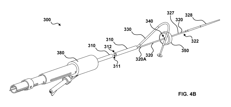
[0017] FIGS. 4A and 4B illustrate in perspective and partially exploded
view a septum
puncture device 300 in a delivery configuration and a deployed configuration,
respectively.
The septum puncture device 300 is shown partially exploded to illustrate the
lumens defined by
the body 310.
[0018] FIGS. 5A and 5B illustrate in cross-sectional view a portion of the
septum
puncture device 300 of FIGS. 4A and 4B, in perspective view and front view,
respectively.
[0019] FIGS. 6A-6H illustrate in side view a deployment sequence of and at
a distal end
portion of the septum puncture device 300, according to an embodiment.
[0020] FIGS. 7A and 7B illustrate a portion of the septum puncture device
300 in its
delivery configuration and its deployed configuration, respectively.
[0021] FIG. 8 illustrates the guide coupler 340 of the septum puncture
device 300
coupled to and between the main shaft 320 and the side catheter guide 330 in
an assembled
arrangement (at right), and in detailed, partially assembled, arrangement (at
left).
[0022] FIG. 9 is a flowchart illustrating a method of using a septum
puncture device to
access a left atrium of a heart of a patient, according to an embodiment.
[0023] FIGS. 10-12 illustrate in perspective bottom view, perspective side
view, and
side view, respectively, a portion of a septum puncture device 500 in a
deployed configuration,
according to another embodiment.
[0024] FIGS. 13A-13F illustrate a partial delivery and deployment sequence
using the
septum puncture device 500 of FIGS. 10-12, according to an embodiment.
[0025] FIGS. 14A-14K illustrate an illustrate an example deployment
sequence of a
septum puncture device 600, according to an embodiment.
[0026] FIGS. 15-17 illustrate a septum puncture device 700 in perspective
view, front
view, and side view, respectively, according to an embodiment.
[0027] FIGS. 18A-18C illustrate a first a guide stabilizer / actuator
("GSA") 850A and a
second GSA 850B, of a septum puncture device 800, in a deflated, delivery
configuration, a
4
CA 03118419 2021-04-30
WO 2020/068841
PCT/US2019/052714
partially inflated, partially deployed configuration, and an inflated,
deployed configuration,
respectively, according to an embodiment.
[0028] FIGS. 19-21 illustrate a septum puncture device 900 in perspective
view, front
view, and detailed, partial perspective view, respectively, that includes two
side catheters,
according to an embodiment.
[0029] FIGS. 22 and 23 illustrate a septum puncture device 1000, in front
view and
perspective view, respectively, having a single GSA and two side catheters,
according to an
embodiment.
[0030] FIGS. 24 and 25 illustrate a septum puncture device 1100, in
perspective front
view and perspective side view, respectively, having a single GSA and a single
side catheter,
according to an embodiment.
[0031] FIGS. 26A and 26B illustrate an example delivery and deployment
sequence of
the septum puncture device 1100 in the context of a heart of a patient,
according to an
embodiment.
[0032] FIG. 27 illustrates a septum puncture device 1200 having a GSA with
a concave
shape and a GSA with a convex shape, according to an embodiment.
[0033] FIG. 28 illustrates a septum puncture device 1300 having a GSA with
a
particular curvature, according to an embodiment.
[0034] FIG. 29 illustrates in top view a septum puncture device 1400 having
a tri-lobed
GSA, according to an embodiment.
[0035] FIG. 30 illustrates in top view a septum puncture device 1500 having
a GSA with
multiple lobes, according to an embodiment.
[0036] FIG. 31 illustrates in side view a septum puncture device 1600
having GSAs
configured to limit blood flow occlusion, according to an embodiment.
[0037] FIG. 32 illustrates in side view a septum puncture device 1700
having GSAs
rotatably offset and interlocked with each other, according to an embodiment.
[0038] FIG. 33 illustrates in side view and top view a septum puncture
device 1800
having an asymmetric GSA, according to an embodiment.
[0039] FIG. 34 illustrates in side view a septum puncture device 1900
defining two
pathways between GSAs, according to an embodiment.
[0040] FIGS. 35A-35D illustrate a deployment sequence of a septum puncture
device
2000, according to an embodiment.
CA 03118419 2021-04-30
WO 2020/068841
PCT/US2019/052714
[0041] FIG. 36 illustrates a portion of a septum puncture device 2100
having an
intracardiac echo ("ICE") sensor, according to an embodiment.
[0042] FIG. 37 illustrates a portion of a septum puncture device 2200
having a camera,
according to an embodiment.
[0043] FIGS. 38 and 39 illustrate in cross-sectional side view and front
view,
respectively, a portion of a septum puncture device 2300, according to an
embodiment.
[0044] FIGS. 40A and 40B illustrate the stylus 2310, according to an
embodiment.
[0045] FIG. 41 illustrates handle 2318, according to an embodiment.
[0046] FIGS. 42A-42D illustrate an example deployment sequence of the
septum
puncture device 2300, according to an embodiment.
[0047] FIGS. 43A and 43B illustrate in side view and cross-sectional side
view,
respectively, a portion of the septum puncture device 2300.
[0048] FIG. 44 illustrates in perspective view a portion of the septum
puncture device
2300 including an end effector.
[0049] FIGS. 45A-45D illustrate the end effector of FIG. 44.
[0050] FIGS. 46A and 46B illustrate in cross-sectional side view and front
view,
respectively, a portion of the septum device 2300, including a stiffening
element.
[0051] FIGS. 47A-48D illustrate a segmented septum puncture device 2400,
according
to an embodiment.
[0052] FIGS. 49-52 illustrate a septum puncture device 2500, according to
an
embodiment.
[0053] FIGS. 53A-53C illustrate various implementations of the septum
puncture
device 2500.
[0054] FIGS. 54A-54C illustrate various implementations of the septum
puncture
device 2500.
[0055] FIG. 55 illustrates a sheath of the septum puncture device 2500.
[0056] FIG. 56 illustrates various implementations of the septum puncture
device 2500.
[0057] FIGS. 57 and 58 illustrate a handle assembly 2680, according to an
embodiment.
[0058] FIGS. 59A-59D illustrate an example deployment sequence of a septum
puncture device, according to an embodiment.
[0059] FIGS. 60A-60D illustrate a portion of a septum puncture device 2700,
according
to an embodiment.
6
CA 03118419 2021-04-30
WO 2020/068841
PCT/US2019/052714
[0060] FIGS. 61A-62B illustrate various implementations of the septum
puncture
device 2700.
[0061] FIGS. 63A-63C illustrate a portion of a septum puncture device 2800,
according
to an embodiment.
[0062] FIG. 64 illustrates a portion of a septum puncture device 2900
having a balloon
covered in mesh, according to an embodiment.
DETAILED DESCRIPTION
[0063] Devices and methods are described herein for use in accessing the
left side of the
heart (e.g., LA) from the right side of the heart (e.g., RA) without requiring
open-heart surgery.
The methods described herein are minimally invasive and utilize a septum
puncture device to
access the left side of the heart in a safe (e.g., atraumatic), efficient,
timely, accurately and
precisely located and repeatable manner. This is accomplished, in part, by
providing a
steerable (e.g., translatable and rotatable) stable platform between the IVC
and SVC from
which a puncture member can be extended laterally and into a target puncture
location (e.g., the
FO) of the atrial septum.
[0064] In some embodiments, a method includes inserting a shaft having (1)
a side
catheter guide attached thereto via a guide coupler, and (2) a guide
stabilizer / actuator
("GSA") in a delivery configuration and slidably attached thereto, into an
inferior vena cava of
a heart of a patient and a superior vena cava of the heart such that the guide
stabilizer/ actuator
is disposed in a right atrium of the heart. The method further includes
applying a distal force to
the side catheter guide such that a distal end of the side catheter guide
deflects laterally about
the guide coupler towards a septum of the heart. The method further includes,
with the guide
stabilizer / actuator in its delivery configuration in the right atrium of the
heart, actuating the
guide stabilizer / actuator to transition the guide stabilizer / actuator from
its delivery
configuration to a deployed configuration. After initiating the applying the
distal force and
with the guide stabilizer / actuator in its deployed configuration, disposing
the side catheter
guide in contact with the side catheter guide to laterally stabilize the side
catheter guide relative
to the shaft. The method further includes with the distal end of the side
catheter guide laterally
deflected about the guide coupler towards the septum and laterally stabilized
by the guide
stabilizer / actuator, extending a side catheter that is disposed within the
side catheter guide
distally from the side catheter guide towards and into contact with the
septum. The method
further includes, with the distal end of the side catheter in contact with the
septum, extending a
7
CA 03118419 2021-04-30
WO 2020/068841
PCT/US2019/052714
septum penetrator that is slidably disposed within the side catheter distally
from the side
catheter such that the septum penetrator pierces the septum.
[0065] In some embodiments, a method includes a shaft having a side
catheter guide
attached thereto via a guide coupler into an inferior vena cava of a heart of
a patient and a
superior vena cava of the heart such that the guide coupler is disposed in a
right atrium of the
heart. The method further includes applying a distal force to a proximal
portion of the side
catheter guide such that a distal end of the side catheter guide deflects
laterally about the guide
coupler towards a septum of the heart. The method further includes, with the
distal end of the
side catheter guide laterally deflected about the guide coupler towards the
septum, extending a
side catheter that is disposed within the side catheter guide distally from
the side catheter guide
towards and into contact with the septum. The method further includes, with
the side catheter
in contact with the septum, extending a septum penetrator that is slidably
disposed within the
side catheter distally from the side catheter such that the septum penetrator
pierces the septum.
[0066] In some embodiments, a method includes inserting a shaft having a
guide
stabilizer / actuator in a delivery configuration and slidably attached
thereto, into an inferior
vena cava of a heart of a patient and a superior vena cava of the heart such
that the guide
stabilizer / actuator is disposed in a right atrium of the heart, a side
catheter guide being coupled
to the guide stabilizer / actuator. The method further includes, with the
guide stabilizer /
actuator in its delivery configuration in the right atrium of the heart,
actuating the guide
stabilizer / actuator to transition the guide stabilizer / actuator from its
delivery configuration to
a deployed configuration such that a distal end of the side catheter guide is
laterally deflected
about the shaft towards the septum of the heart and laterally stabilized in
part by the guide
stabilizer / actuator being in its deployed configuration. With the guide
stabilizer / actuator in
its deployed configuration, the side catheter guide extends proximally from
its distal end that is
disposed beyond a first side of the shaft, across the shaft, and to a second
side of the shaft
opposite the first side of the shaft, and then turns and extends proximally
towards a proximal
end of the shaft. The method further includes, with the distal end of the side
catheter guide
laterally deflected about the shaft towards the septum and laterally
stabilized in part by the
guide stabilizer / actuator, extending a side catheter that is disposed within
the side catheter
guide distally from the distal end of the side catheter guide towards and into
contact with the
septum. The method further includes, with the side catheter in contact with
the septum,
extending a septum penetrator that is slidably disposed within the side
catheter distally from
the side catheter such that the septum penetrator pierces the septum.
8
CA 03118419 2021-04-30
WO 2020/068841
PCT/US2019/052714
[0067] In some embodiments, an apparatus includes a body that defines a
first lumen
and a second lumen. The apparatus further includes a shaft that has a first
section fixedly
coupled to the body and extends distally from the first lumen of the body, and
a second section
disposed partially within and telescopable with respect to the first section
of the shaft. The
apparatus further includes a guide wire coupler that is coupled to the body
and extends distally
from within a lumen defined by the shaft. The guide wire coupler defines a
guide wire lumen
configured to slidably receive a first guide wire. The apparatus further
includes a side catheter
guide that is coupled to the body and extends distally from within the second
lumen of the
body. The side catheter guide is coupled to the first section of the shaft via
a guide coupler.
The side catheter guide is configured to be transitioned between a delivery
configuration and a
deployed configuration in which a distal end of the side catheter guide is
laterally deflected
about the guide coupler when transitioned from its delivery configuration to
its deployed
configuration. The apparatus further includes a guide stabilizer / actuator
that is coupled to the
second section of the shaft and configured to transition between a delivery
configuration and a
deployed configuration to cause the distal end of the side catheter guide to
further laterally
deflect about the guide coupler and laterally stabilize. The side catheter
guide defines a lumen
that is configured to slidably receive a side catheter. The side catheter
defines a lumen
configured to slidably receive a puncture member. The puncture member is
configured to
puncture tissue of a patient.
[0068] In some embodiments, an apparatus includes a body that defines a
first lumen
and a second lumen. The apparatus further includes a shaft that has a first
section fixedly
coupled to the body and extends distally from the first lumen of the body, and
a second section
disposed partially within and telescopable with respect to the first section
of the shaft. The
apparatus further includes a guide wire coupler that is coupled to the body
and extends distally
from within a lumen defined by the shaft. The guide wire coupler defines a
guide wire lumen
configured to slidably receive a first guide wire. The apparatus further
includes a side catheter
guide that is coupled to the body and extends distally from within the second
lumen of the
body. The side catheter guide is coupled to the first section of the shaft via
a guide coupler.
The side catheter guide is configured to be transitioned between a delivery
configuration and a
deployed configuration in which a distal end of the side catheter guide is
laterally deflected
about the guide coupler when transitioned from its delivery configuration to
its deployed
configuration. The side catheter guide defines a lumen that is configured to
slidably receive a
9
CA 03118419 2021-04-30
WO 2020/068841
PCT/US2019/052714
side catheter. The side catheter defines a lumen configured to slidably
receive a puncture
member. The puncture member is configured to puncture tissue of a patient.
[0069] In some
embodiments, an apparatus includes a shaft having a proximal end and a
distal end, and a lumen extending therethrough. The shaft defines (1) a first
aperture, and (2) a
second aperture and a third aperture both disposed distal to the first
aperture. The apparatus
further includes a first guide stabilizer / actuator ("GSA") and a second GSA
both (1)
circumferentially disposed about the shaft, and (2) configured to transition
between a delivery
configuration and a deployed configuration. The apparatus further includes a
side catheter
guide coupled to the shaft and extending distally into the lumen at the
proximal end of the shaft,
exiting the shaft through the first aperture, and extending distally between
the first GSA and the
second GSA and into the second aperture, and then exiting the shaft through
the third aperture.
The first GSA and the second GSA are configured such that transition from the
delivery
configuration to the deployed configuration causes a distal end of the side
catheter guide to (1)
laterally deflect about, and (2) stabilized relative to, a central axis of the
shaft. The side
catheter guide defines a lumen configured to slidably receive a side catheter.
The side catheter
defines a lumen configured to slidably receive a puncture member that is
configured to
puncture tissue of a patient.
[0070] As used
herein, the terms "proximal" and "distal" refer to the direction closer to
and away from, respectively, an operator (e.g., a surgeon, physician, nurse,
technician, etc.)
who would insert the septum puncture device into the patient, with the tip-end
(i.e., distal end)
of the device inserted inside a patient's body first. Thus, for example, the
end of a main shaft
described herein first inserted inside the patient's body would be the distal
end, while the
opposite end of the main shaft (e.g., the end of the main shaft being
manipulated by the
operator) would be the proximal end of the main shaft.
[0071] As used
herein, the terms "advance," "advanced," and "advancing" each refer to
distal movement. Advancing a device within a patient's vasculature, for
example, refers to
moving at least a portion of the device distally within the patient's
vasculature. Similarly, as
used herein, the terms "withdraw," "withdrawn,", and withdrawing" each refer
to proximal
movement. Withdrawing a device within a patient's vasculature, for example,
refers to moving
at least a portion of the device proximally within the patient's vasculature.
In some instances,
advancing and withdrawing can refer to relative movement of the device itself
Advancing a
side catheter, for example, can refer to moving a side catheter distally
relative to a side catheter
guide to which the side catheter is movably coupled. Similarly, withdrawing
the side catheter,
CA 03118419 2021-04-30
WO 2020/068841
PCT/US2019/052714
for example, can refer to moving the side catheter proximally relative to the
side catheter guide
to which the side catheter is movably coupled.
[0072] The septum puncture device 100 can be used to access a left side of
the heart
(e.g., left atrium) from the right side of the heart (e.g., right atrium) and
to deliver a guidewire
to the left side of the heart. As shown in FIG. 1A, the septum puncture device
100 includes a
body 110 coupled to a main shaft 120, a side catheter guide 130, a side
catheter 160, and a
septum penetrator 170. The main shaft 120 is coupled to the side catheter
guide 130 via a guide
coupler 140, the side catheter guide 130 is coupled to the side catheter 160,
and the side
catheter 160 is coupled to the septum penetrator 170, as shown in FIG. 1A. The
side catheter
guide 130 is configured to define a pathway through or across which the side
catheter 160 can
travel (e.g., be advanced and/or withdrawn). Said another way, and as
described in further
detail herein, the side catheter guide 130 can be manipulated (e.g., actuated
from a delivery
state to a deployed state) to guide the side catheter 160 in a desired
direction (the actuated or
deployed state of the side catheter guide 130 is shown in FIG. 1B), e.g.,
towards the left atrium.
[0073] As described in further detail herein, the guide coupler 140 can
couple the side
catheter guide 130 to the main shaft 120 to minimize or prevent relative
translational
movement between the main shaft 120 and the side catheter guide 130, but to
allow relative
rotational movement between the main shaft 120 and the side catheter guide
130, as illustrated
schematically in FIG. 1B. In this manner, the guide coupler 140 can facilitate
transition of the
side catheter guide 130 from a delivery configuration (e.g., parallel to or
substantially parallel
to the main shaft 120), e.g., for insertion through the patient's vasculature
and into the RA, to a
deployed configuration such that a distal end of the side catheter guide 130
is deflected laterally
(e.g., perpendicular or substantially perpendicular) relative to the main
shaft 120, e.g., towards
the patient's left atrium (e.g., the FO of the atrial septum). In some
embodiments, the guide
coupler 140 can be a hinge to facilitate lateral deflection of the side
catheter guide 130 relative
to the main shaft 120, as described in further detail herein. In such
embodiments, for example,
a distal force can be applied to a proximal end portion of the side catheter
guide 130, thereby
causing the hinge to rotate and cause a distal end portion of the side
catheter guide (i.e., a
portion of the side catheter guide 130 that extends distal to the guide
coupler 140) to laterally
deflect. In some implementations, the amount of lateral deflection or the
defined between the
side catheter guide 130 and the main shaft 120 after such lateral deflection
is adjustable by the
operator intra-procedure, i.e., in real-time, such that, for example, the
operator has procedural
flexibility when locating the target puncture location.
11
CA 03118419 2021-04-30
WO 2020/068841
PCT/US2019/052714
[0074] In some implementations, one or more of the main shaft 120, the side
catheter
guide 130, or the side catheter 160 can have a circular cross-sectional shape,
while in other
implementations, one or more of the main shaft 120, the side catheter guide
130, or the side
catheter 160 can have a non-circular cross-sectional shape. In some instances,
for example, the
main shaft 120 and the side catheter guide 130 can have circular cross-
sectional shapes, and
can be operably coupled together, as discussed in further detail herein, such
that the main shaft
120 and the side catheter guide 130 are at least partially disposed side-by-
side (e.g., during
delivery). In other instances, for example, the main shaft 120 may have a non-
circular
cross-section (e.g., a half-moon shape, c-shape a convex or concave shape, or
any other
suitable noncircular cross-sectional shape) such that when coupled to the side
catheter guide
130, a portion of the side catheter guide 130 can be nestled within a space
defined at least in
part by the non-circular curvature of the main shaft 120. In this manner, the
collective
cross-sectional area, footprint, diameter, etc. of the main shaft 120 and side
catheter guide 130
can be reduced. In some instances, a similar relationship can be had by the
main shaft 120 and
the side catheter 160 (e.g., in embodiments in which a septum puncture device
does not have a
side catheter guide).
[0075] In some embodiments, the septum puncture device 100 includes a side
catheter
guide stabilizer/ actuator ("GSA") 150 (also referred to herein as "guide
stabilizer/ actuator"),
and a GSA actuator 154 operably coupled to the GSA 150 and configured to
actuate the GSA
150. In some implementations, the GSA 150 can be configured to stabilize
(e.g., laterally,
axially (proximally or distally), e.g., with respect to the main shaft 120)
the side catheter guide
130 to facilitate the side catheter's 160 engagement with the FO and the
septum penetrator's
170 penetration of the FO. In this manner, the guide coupler 140 can laterally
deflect the side
catheter guide 130, and the GSA 150 can stabilize the side catheter guide 130
(and in turn the
side catheter 160, optional end effector 162, and septum penetrator 170) to
optimize
subsequent penetration of the septum and access to the left atrium. In some
implementations,
in addition to or instead of stabilizing the side catheter guide 130, the GSA
150 can be
configured to laterally deflect (e.g., laterally deflect in addition to the
lateral deflection caused
or facilitated by the guide coupler 140, as described above) the side catheter
guide 130 (and in
turn the side catheter 160 and septum penetrator 170, given their coupling to
the side catheter
guide 130). In this manner, in some implementations, the guide coupler 140 and
the GSA 150
can collectively laterally deflect and stabilize the side catheter guide 130
(and in turn the side
12
CA 03118419 2021-04-30
WO 2020/068841
PCT/US2019/052714
catheter 160, optional end effector 162, and septum penetrator 170) to
optimize subsequent
penetration of the septum and access to the left atrium.
[0076] The GSA 150 can be manipulatable in any manner suitable to provide
the
above-described functionality. In some embodiments, for example, the GSA 150
can be a
balloon, and as such, it can be configured to be inflatable and deflatable. In
such embodiments,
the GSA 150 can be fluidically coupled to a lumen extending from the GSA 150
to the GA
actuator 154 such that the GA actuator 154 can selectively deliver fluid to
the GA actuator 154
to inflate the GSA 150 (i.e., deploy the GSA 150), and selectively withdraw
fluid from the
GSA 150 to deflate the GSA 150 for removal of the GSA 150 from the heart
(e.g., after left
atrium access has been achieved).
[0077] In embodiments in which the GSA 150 is a balloon, the balloon can
have any
shape and size suitable to perform the desired functions described herein. In
some
embodiments, for example, the balloon can be cone-shaped, while in other
embodiments, it can
be at least partially concave, convex, circular, oval, or the like. Further,
in some embodiments,
the balloon can have one or more lobes, e.g., it can be bi-lobed or tri-lobed,
to, for example,
allow blood flow along the balloon and past the device. Further, the balloon
can have
additional features configured to improve stabilization of the side catheter
guide 130 (e.g.,
improve coupling between the balloon and the side catheter guide 130). In some
embodiments,
for example, a balloon can have dimples, protrusions, ridges, adhesives, etc.
[0078] The
balloon can be formed of any material or combination of materials suitable
to perform its functionality described herein. In some embodiments, for
example, the balloon
can be formed of one or more of Polyethylene, Polyethylene terephthalate
("PET"), a polymer,
a thermoplastic polymer, an elastomer, nylon, polyurethane, any non-compliant
material, etc.
The balloon can be configured to be inflated to any suitable pressure, e.g.,
from about 2 ATM
to about 20 ATM, as an example. In some instances, higher inflation pressures
can result in
greater or improved rigidity of the balloon, thereby providing better
stabilization of the side
catheter guide, side catheter, septum penetrator, etc..
[0079] The GSA 150 can be formed of any material suitable to perform its
functions
described herein. In some embodiments the GSA 150 can include or be formed of
shape
memory material (e.g., Nitinol) and configured to be transitioned between a
delivery /
withdrawal configuration in which the GSA 150 is constrained, compressed, or
otherwise
placed in a relatively small arrangement, and a deployed configuration in
which the GSA 150 is
13
CA 03118419 2021-04-30
WO 2020/068841
PCT/US2019/052714
unconstrained, expanded, or otherwise placed in a larger arrangement
sufficient to laterally
deflect or stabilize the side catheter guide 130 as described in further
detailed herein.
[0080] Similar to the guide coupler 140, in some embodiments, the GSA 150
can
include or be formed of radiopaque material to assist the operator in locating
that portion of the
septum puncture device 100 before, during, or after deployment. In this
manner, the operator
can in real time selectively position the septum penetrator 170 in a position
suitable to penetrate
the FO upon actuation of the septum penetrator 170. In embodiments in which
the GSA 150 is
a balloon, for example, in some instances the GSA 150 can be inflated with a
contrast agent (or
a combination of a contrast agent and another fluid, such as saline) to
provide visualization
(e.g., under any suitable imaging modality) for the operator when the GSA 150
is disposed
within the patient.
[0081] As described in further detail herein, with the side catheter guide
130 laterally
deflected and stabilized at a suitable angle relative to the FO or the main
shaft 120, and with (1)
one or more landmark portions of the septum puncture device 100 and (2) a
desired puncture
location (e.g., the FO) on the septum visible to the operator from outside the
patient, the
operator can manipulate the main shaft 120 translationally or rotationally in
any suitable
manner to align the side catheter guide 130 with the FO.
[0082] Further as shown in FIG. 1A, the septum puncture device 100 includes
a guide
wire coupler 122 configured to couple the main shaft 120 to a guide wire (not
shown in FIG.
1A) to facilitate delivery of the septum puncture device 100 into a patient
(e.g., through the
vasculature of the patient) and to the patient's heart, and a guide wire
coupler 172 configured to
couple a guide wire (not shown in FIG. 1A) to the septum penetrator 170, to
facilitate delivery
of that guide wire to the left side of the heart (e.g., the left atrium).
[0083] Further as shown in FIG. 1A, the septum puncture device 100
optionally
includes a shaft actuator 124 operably coupled to the main shaft 120 and
configured to actuate
the main shaft 120 to advance or withdraw the main shaft 120 relative to the
body 110. The
septum puncture device 100 further includes (1) a side catheter actuator 164
operably coupled
to and configured to actuate the side catheter 160 to advance or withdraw the
side catheter 160,
thereby transitioning the side catheter 160 between a delivery configuration
and a deployed
configuration (the side catheter 160 shown in an actuated or deployed
configuration in FIG.
1B), and a (2) a septum penetrator actuator (or "penetrator actuator") 174 to
actuate the septum
penetrator 170 to advance or withdraw the septum penetrator 170, thereby
transitioning the
septum penetrator between a delivery configuration and a deployed
configuration (the septum
14
CA 03118419 2021-04-30
WO 2020/068841
PCT/US2019/052714
penetrator 170 shown in an actuated or deployed configuration in FIG. 1B), as
described in
further detail herein.
[0084] Further as shown in FIG. 1A, the septum puncture device 100
optionally
includes a GSA ("GA") 150 coupled to the main shaft 120. The optional GSA 150
is operably
coupled to a GA actuator 154 that is configured to actuate the GSA 150, as
described in further
detail herein.
[0085] Further as shown in FIG. 1A, the septum puncture device 100
optionally
includes an end effector 162 coupled to and extending distally from the side
catheter 160. The
end effector 162 is configured to facilitate subsequent puncture through a
target puncture
location, such as, for example, the FO of the septum of the heart. The end
effector 162 can be
configured, for example, to contact or tent the FO, as described in further
detail herein. Such
contact or tenting of the FO can, for example, reduce or minimize the force
required to
penetrate the FO and/or provide for improved force distribution to the FO. The
end effector
162 can be configured to prevent inadvertent puncturing of and/or damage to
the FO with the
end effector 162.
[0086] In some embodiments, the end effector 162 is formed of or includes a
radiopaque
material such that the end effector 162 can be visualized when within the
heart from outside the
patient under any suitable imaging modality (e.g., fluoroscopy,
echocardiography, etc.), to
facilitate an operator in deploying the end effector 162, e.g., locating the
end effector 162
within the heart or relative to the FO in preparation for deploying the septum
penetrator 170.
[0087] In some embodiments, the end effector 162 can include multiple
configurations,
e.g., a delivery or withdrawal configuration, in which the end effector 162 is
configured to be
routed through the patient's vasculature, and a deployed configuration in
which the end
effector 162 is configured to facilitate subsequent penetration of the FO, as
described in further
detail herein. In such embodiments, for example, the end effector 162 can be
delivered to the
heart in a compressed, deflated, or otherwise relatively small configuration,
and then
transitioned into a deployed configuration in which it is expanded, inflated,
or otherwise
increased in size to then contact or tent the FO. Further, in some
embodiments, after
deployment of the end effector 162, the end effector 162 can be transitioned
to a withdrawal
configuration (which can be the same as or similar to its delivery
configuration) in which the
end effector 162 is in a compressed, deflated, or otherwise small
configuration to assist in
removal of the end effector 162 from the patient.
CA 03118419 2021-04-30
WO 2020/068841
PCT/US2019/052714
[0088] The end effector 162 can be formed of any suitable material(s) to
facilitate its
functionality described herein. In some embodiments, for example, the end
effector 162 can be
formed of shape memory material(s) (e.g., Nitinol) or a polymer, or a
combination thereof
(e.g., Nitinol coated with a polymer), such that it can be transitioned
between a constrained or
compressed arrangement (e.g., delivery or withdrawal configuration) and an
unconstrained or
expanded arrangement (deployed configuration). In some embodiments, for
example, the end
effector 152 can be or include a balloon such that it can be delivered to the
heart in a deflated
arrangement and then inflated (e.g., via an inflation lumen fluidically
coupled to and extending
proximally from the end effector 162, not shown) to a deployed configuration.
Various further
embodiments of an end effector are described in further detail below.
[0089] Each of the main shaft 120, the guide wire coupler 122, the side
catheter guide
130, the guide coupler 140, the optional GSA 150, the side catheter 160, the
septum penetrator
170, and the guide wire coupler 172 are translatable (e.g., distally
advanceable and/or
extendable, and proximally withdrawable and/or retractable) relative to the
body 110. The side
catheter 160 is translatable relative to the side catheter guide 130, and the
septum penetrator
170 is translatable relative to the side catheter 160, as described in further
detail herein.
[0090] The septum penetrator 170 can be sized, shaped, and formed of any
material
suitable to effectively penetrate and traverse a target tissue such as the FO.
In some
embodiments, for example, the septum penetrator 170 can be a needle. In some
embodiments,
the septum penetrator 170 can be a non-coring needle (e.g., a needle with a
sharp tip that has a
cutting edge, such as, for example, a Quincke-type needle). In some
embodiments, the septum
penetrator 170 can have variable material properties. In such embodiments, for
example, a
distal portion of the septum penetrator 170 can have a stiffness greater than
a stiffness of a
portion proximal to that distal portion. In this manner, the stiffer distal
portion can be
configured for penetration through the septum, while the portion proximal can
be configured
for delivery through the patient's vasculature. In some embodiments, the
septum penetrator
170 can be solid-tipped and can be electrified with radiofrequency ("RF")
energy to puncture
the FO.
[0091] The septum penetrator 170 can have any suitable length, for example,
any length
suitable to reach the LA. In some embodiments, for example, the septum
penetrator 170 can
have an effective length (i.e., the length extendable from the distal end of
the side catheter 160
(or from the distal end of the end effector 162) of about 5mm to about 25 mm.
In some
instances, an effective length of the septum penetrator 170 can be about 8mm
or about lOmm,
16
CA 03118419 2021-04-30
WO 2020/068841
PCT/US2019/052714
or any length therebetween. In some embodiments, the septum penetrator 170 can
contain or
be configured to receive a stylet to limit or minimize tissue coring. In some
embodiments, the
septum penetrator 170 can include a pressure transducer (not shown) configured
to monitor
pressure through a lumen of the septum penetrator 170. In some embodiments, a
port or lueuer
lock can be incorporated into the septum puncture device 100 to flush the
septum penetrator
170.
[0092] Turning to FIGS. 2A and 2B to describe the septum puncture device
100 (1) in
context with the anatomy of a patient and (2) in a sample procedure to access
the LA of the
patient, FIG. 2A is a schematic illustration of the septum puncture device 100
disposed in a
delivery configuration within the RA of the heart and coupled to a first guide
wire GW1
extending from the IVC across the RA and into a SVC and FIG. 2B is a schematic
illustration
of the septum puncture device 100 disposed in a deployed configuration and
such that it has
accessed and delivered to the LA a second guide wire that can be used to
provide subsequent
access to the LA.
[0093] In use, prior to introducing into the patient the septum puncture
device 100, a
guide wire GW1 can be inserted through an entry site of the patient (e.g.,
femoral vein puncture
site) (not shown) and advanced through the patient's vasculature across the
IVC and RA, and
into the SVC using known, suitable techniques for guidewire delivery. With the
guide wire
GW1 disposed in such a manner, the septum puncture device 100 can be movably
coupled to
the guide wire GW1 via the guide wire coupler 122 and advanced from the entry
site of the
patient towards the heart. In some embodiments, the guide wire coupler 122 can
be a lumen
defined by the main shaft 120 through which the guide wire GW1 can be disposed
and such
that the main shaft 120 can be slidably disposed about the guide wire GW1. The
guide wire
GW1 can be any suitable size. In some embodiments, for example, the guide wire
GW1 can
have a diameter of about 0.014 inches to about 0.035 inches in diameter. In
some
embodiments, the guide wire GW1 can be about 0.025 inches diameter. With the
guide wire
coupler 122 movably coupled to the delivered guide wire GW1, the septum
puncture device
100 can be advanced along the guide wire GW1 into the heart, as shown in FIG.
2A. More
specifically, with the main shaft 120 coupled to (1) the body 110 and (2) the
side catheter guide
130 via the guide coupler 140, the body 110, the main shaft 120, the guide
coupler 140, the side
catheter guide 130, the side catheter 160, the septum penetrator 170, and the
guide wire coupler
172 all can be advanced into the heart of the patient as shown in FIG. 2A,
such that body 110
extends through the IVC and into the RA, and the main shaft 120 extends into
the SVC. With
17
CA 03118419 2021-04-30
WO 2020/068841
PCT/US2019/052714
the main shaft 120 spanning the IVC, RA, and SVC, the main shaft 120 can
provide a
foundation or backstop against which the side catheter guide 130, side
catheter 160, and
septum penetrator 170 can be deployed and advanced towards the septum, as
described in
further detail herein.
[0094] In some instances, a distal end of the (1) main shaft 120, (2) side
catheter guide
130, (3) side catheter 160, and septum penetrator 170 (and accompanying
couplers, e.g., the
guide wire coupler 122 and the guide wire coupler 172), can be disposed within
the body 110
(e.g., within one or more lumens (not shown) defined by the body 110). In this
manner, during
delivery, the patient's anatomy can be protected or shielded by the body 110
to avoid
inadvertent trauma to or contact with the patient's anatomy from such
components. With a
distal end of the body 110 disposed in or near the RA, the body 110 can be
withdrawn (and/or
one or more of the components movably coupled thereto can be advanced),
thereby exposing
the side catheter guide 130 and guide coupler 140 within the RA.
[0095] With the side catheter guide 130 exposed within the RA and
translationally
fixedly coupled to the main shaft 120 via the guide coupler 140, the side
catheter guide 130 can
be actuated to laterally deflect the distal end of the side catheter guide 130
(and as a result, also
the side catheter 160, the septum penetrator 170, and the guide wire GW2 if
disposed in the
side catheter guide 130 during its lateral deflection), as shown in FIG. 2B.
The side catheter
guide 130 can be laterally deflected at any angle suitable to direct the side
catheter 160 and
septum penetrator 170, which are movably attached to the side catheter guide
130, towards the
target penetration site, e.g., the FO, as shown in FIG. 2B. In some instances,
an optimal angle
of entry to the FO is 90 degrees or substantially 90 degrees relative to a
surface line tangent to
the FO, which can be about a similar angle relative to a central axis of the
main shaft 120. Such
a perpendicular (or substantially perpendicular) angle of entry can minimize
the force required
to penetrate the FO because the entire or substantially entire force vector is
directed at the plane
of the FO (rather than a tangential approach). Additionally, such a
perpendicular (or
substantially perpendicular) angle of entry, given the nature of a patient's
anatomy, directs the
septum penetrator to a relatively large open space within the LA, thereby
minimizing risk of
inadvertent puncture within the LA (e.g., inadvertent puncture of a wall of
the LA).
[0096] In other instances, the angle of entry relative to the FO or
relative to the central
axis of the main shaft 120 can be anywhere within a range of about 50 degrees
to about 90
degrees. In some instances, the preferred angle of entry can be selected based
on a particular
therapy planned for the left side of the heart. The angle of entry, for
example, defines the
18
CA 03118419 2021-04-30
WO 2020/068841
PCT/US2019/052714
trajectory for the subsequent therapeutic device to enter the left side of the
heart, and so in some
instances an optimal angle and location of entry through the FO is based on a
particular
therapeutic device or procedure.
[0097] Note that the guide wire GW2 can be delivered in any suitable
manner. In some
instances, for example, the guide wire GW2 is disposed within the side
catheter guide 130
during delivery of the side catheter guide 130, while in other instances the
guide wire GW2 is
inserted at a later time during the procedure, e.g., after the septum
penetrator 170 has
penetrated the FO and reached the LA.
[0098] With the side catheter guide 130 transitioned to its deployed
configuration, in
which the side catheter guide 130 is laterally deflected towards the FO, the
side catheter
actuator 164 can be actuated to advance the side catheter 160 along a path
defined at least in
part by the side catheter guide 130 and towards the FO. In some instances the
side catheter 160
is advanced until it's distal end tents or otherwise contacts the FO. For
embodiments that
include the end effector 162, the side catheter 160 can be advanced until the
end effector 162
extending from the distal end of the side catheter 160 tents or otherwise
contacts the FO.
[0099] In embodiments in which the end effector 162 is expandable and
compressible,
the end effector 162 can be delivered to the Right Atrium RA in a compressed
or relatively
small configuration, and then transitioned to a deployed configuration in
which the end effector
162 is expanded to a relatively larger configuration, and then advanced to
engage with the FO.
After sufficient penetration of the Atrial Septum AS with the septum
penetrator 170, as
described in further detail herein, the end effector 162 can be transitioned
to its retracted or
compressed configuration suitable to be withdrawn from the patient. In
embodiments in which
the side catheter 160 is slidably disposed within a lumen defined by the side
catheter guide 130,
the end effector 162 can similarly be slidably disposed within the lumen
defined by the side
catheter guide 130 such that the side catheter guide 130 contains the end
effector 162 in its
constrained or compressed configuration during delivery, and then as the side
catheter actuator
164 is actuated to advance the side catheter 160 distally from the distal end
of the side catheter
guide 130, the end effector 162 can transition to its expanded or
unconstrained configuration as
or after it exits the lumen of the side catheter guide 130.
[0100] With the side catheter 160 (or end effector 162) in sufficient
contact with the FO,
the penetrator actuator 174 can be actuated to advance the septum penetrator
170 relative to and
along a path defined at least in part by the side catheter 160. The septum
penetrator 170 can be
advanced through the FO and across the Atrial Septum AS and into the Left
Atrium LA. In
19
CA 03118419 2021-04-30
WO 2020/068841
PCT/US2019/052714
some embodiments, the side catheter 160 defines a lumen through which the
septum penetrator
170 is slidably disposed such that actuating the penetrator actuator 174
advances the septum
penetrator 170 through the lumen of the side catheter 160. The septum
penetrator 170 can be
advanced in this manner to penetrate the FO and to extend into the left atrium
LA. During such
penetration, the main shaft 120 can provide lateral or axial stability to the
septum penetrator
170.
[0101] As the distal end of the septum penetrator 170 is advanced across
the Atrial
Septum AS and into the Left Atrium LA, the guide wire GW2 can follow via the
guide wire
coupler 172 and the septum penetrator 170 in instances in which the guide wire
GW2 is
coupled to the side catheter guide 130 during delivery of the side catheter
guide 130. In other
instances, the guide wire GW2 can be inserted at a later time during the
procedure, e.g., after
the septum penetrator 170 has penetrated the FO and reached the LA In some
embodiments,
the guide wire coupler 172 is a lumen defined by the septum penetrator 170 and
through which
the guide wire GW2 can be slidable disposed. In such embodiments, the guide
wire GW2 can
be disposed within the lumen of the septum penetrator 170 during delivery and
deployment of
the septum penetrator 170 into the Left Atrium LA.
[0102] With the septum penetrator 170 and the guide wire GW2 disposed
within the
Left Atrium LA, the guide wire GW2 can be further advanced into the Left
Atrium LA by
manipulation of the guide wire GW2 at its proximal end, and/or the septum
penetrator 170 can
be withdrawn from the Left Atrium LA, across the puncture or entry site of the
FO, leaving the
guide wire GW2 within the Left Atrium LA.
[0103] With the guide wire GW2 delivered to the Left Atrium LA, and
extending
proximally from the Left Atrium LA across the puncture or entry site of the
FO, into the Right
Atrium RA, the IVC, and through the vasculature of the patient to the entry
point of the patient
(for subsequent access to the Left Atrium AS), the septum puncture device 100
can be
withdrawn from the heart proximally over guide wire GW2 and from the patient.
[0104] The guide wire GW2 can be any guide wire suitable to provide
desirable
subsequent access to the Left Atrium LA. In some embodiments, for example, the
guide wire
GW2 can be a pigtail, atraumatic guide wire or other suitable guide wire
conventionally used in
transseptal procedures. For example, the guide wire GW2 can have a flexible,
spiral tip,
pigtail, and can be configured to anchor the septum puncture device 100 to the
LA, thereby
limiting or preventing the guide wire GW2 from being inadvertently withdrawn
or removed
from the LA in response to or while the septum puncture device 100 is being
withdrawn along
CA 03118419 2021-04-30
WO 2020/068841
PCT/US2019/052714
the guide wire GW2 and from the patient. Another example guide GW2 can be a
ProTrackTm
Pigtail Wire from Baylis Medical Company, Inc.
[0105] The septum puncture device 100 can be configured to be withdrawn
from the
patient in any suitable sequence (e.g., after the guide wire GW2 has been
delivered to the Left
Atrium LA). With the guide wire GW2 disposed within the Left Atrium LA, for
example, the
portions of the septum penetrator 170 and guide wire coupler 172 disposed
within the Left
Atrium LA can be withdrawn relative to the guide wire GW2 and through the
puncture site in
the FO and into the Right Atrium RA. In embodiments in which the side catheter
160 defines a
lumen through which the septum penetrator is slidably disposed, the septum
penetrator 170 can
be withdrawn relative to and into the lumen defined by the side catheter 160.
In this manner,
the septum penetrator 170, and particular it's distal that is designed to
penetrate tissue, can be
sheathed or shielded by the side catheter 160 to facilitate safe withdrawal
from the patient and
avoid inadvertent contact with the patient's heart or vasculature during
removal of the septum
puncture device 100 from the patient.
[0106] Similarly, the side catheter 160 can be withdrawn relative to the
side catheter
guide 130. For example, in embodiments in which the side catheter guide 130
defines a lumen
through which the side catheter 160 is slidably disposed, the side catheter
160 can be
withdrawn into the lumen of the side catheter guide 130. In embodiments in
which the septum
puncture device 100 includes an end effector 162, the side catheter guide 160
can be withdrawn
relative to and into the lumen of the side catheter guide 130 such that the
end effector 162 is
also withdrawn into the lumen of the side catheter guide 130. In embodiments
in which the end
effector 162 has a deployed configuration with a diameter larger than an
internal diameter of
the side catheter guide 130, the end effector 162 can be configured to be
transitioned from its
deployed configuration to its withdrawal (or delivery) configuration. For
example, if the end
effector 162 is a balloon, it can be deflated and then withdrawn into the
lumen of the side
catheter guide 130. As another example, if the end effector 162 includes or is
formed of shape
memory material, the end effector 162 can be compressed, constrained, or
otherwise
transitioned to a smaller arrangement such that it can be withdrawn into the
side catheter guide
130. In some instances, withdrawal of the end effector 162 into the side
catheter guide 130 can
cause the end effector 162 to transition to its constrained or compressed
configuration.
[0107] Further, the side catheter guide 130 can be configured to transition
from its
deployed configuration in which its distal portion is laterally deflected
relative to the main
shaft 120 to its withdrawal (or delivery) configuration in which the side
catheter guide 130 is at
21
CA 03118419 2021-04-30
WO 2020/068841
PCT/US2019/052714
least substantially linear and parallel to the main shaft 120. In some
embodiments, for
example, a proximal force can be applied to a proximal end portion of the side
catheter guide
130 to withdraw the side catheter guide 130 relative to the main shaft.
[0108] With the septum puncture device 100 disposed as shown in FIG. 2A,
for
example, after delivering the guide wire GW2, the septum puncture device 100
can be
withdrawn from the heart and from the patient. For example, the body 110, and
all of the
components coupled thereto, can be withdrawn from the heart, through the
patient's
vasculature, and out through the initial entry site into the patient (e.g., a
the femoral puncture
site).
[0109] Although embodiments described herein refer to introducing a guide
wire and
septum puncture device into the patient's vasculature, and across the IVC and
RA, and into the
SVC, access to the RA for purposes of deploying a septum penetrator, can be
accomplish in a
variety of ways. In some embodiments, for example, the guide wire and septum
puncture
device can be inserted into a patient's jugular vein (e.g., right internal
jugular vein), and then
advanced into and across the SVC and RA, and into the IVC, such that a distal
end of the
septum puncture device is disposed in the IVC (or beyond).
[0110] Although embodiments described herein refer to a single FO puncture
to deliver
a single guide wire to the LA, it should be understood that the septum
puncture devices
described herein can be used to perform multiple punctures and to deliver
multiple guide wires.
In some instances, for example, a double puncture and delivery of two guide
wires may be
desirable, e.g., in connection with an atrial fibrillation ablation procedure.
In such instances,
the septum puncture devices described herein can be deployed twice to puncture
the septum
twice, with each puncture providing access to deliver a guide wire, as
described herein. In
some procedures that require multiple punctures and guide wires delivered to
the LA, for
example, it can be crucial that the punctures are in a particular location and
located a particular
distance from each other, and as described through this disclosure, the septum
puncture devices
described herein provide just that.
[0111] Further, instead of using a septum puncture device described herein
to
administer multiple punctures in series (e.g., with a single penetrator,
single side catheter,
single side catheter guide, etc.), in some embodiments, any of the septum
puncture devices
described herein can be modified to incorporate additional components. For
example, in some
instances, a septum puncture device can include a body and a main shaft
(similar to septum
puncture device 100), but also include two side catheter guides, two side
catheters, two end
22
CA 03118419 2021-04-30
WO 2020/068841
PCT/US2019/052714
effectors, two septum penetrators, and two guide couplers (for the guide wires
being
delivered), and optionally one or two guide couplers and one or two guide
stabilizer / actuators.
In this manner, two side catheter guides can be deployed (i.e., laterally
deflected and stabilized)
simultaneously, and then two side catheters (optionally with end effectors)
can be advanced,
optionally simultaneously, to contact the septum, and then two septum
penetrators can be
advanced, optionally simultaneously, to penetrate the septum. With two
punctures in the
septum, two guide wires can then be delivered, optionally simultaneously. In
such instances,
the preferred distance between the two punctures can be selectively defined by
the distance
between the side catheters from which the septum penetrators are advanced.
[0112] FIG. 3 illustrates a method 200 of using the septal puncture device
100 to access
a left atrium of a heart of a patient, according to an embodiment. At 201, the
guide wire GW1
is inserted through the IVC, across the RA, and into SVC of the heart (e.g.,
via a femoral vein
puncture and through the patient's vasculature disposed between the femoral
vein puncture site
and the IVC). At 202, the septal puncture device 100 is delivered over the
guide wire GW1
until a distal end of a main shaft 110 is disposed within the SVC. At 204, the
GSA 150 is
actuated to laterally deflect and direct the side catheter guide 130 towards
the FO. Optionally,
at 206, the main shaft 110 and the side catheter guide 130 are selectively
positioned (e.g.,
translated or rotated) relative to the FO. Optionally, at 208, the end
effector 162 is deployed.
At 210, the end effector 162 (or distal end of side catheter) is advanced
against and into contact
with the FO (e.g., to tent the FO). Optionally, at 212, the end effector 162
(or distal end of side
catheter 130) is visualized from outside the patient, and if necessary, the
main shaft 110 or the
side catheter guide 130 are adjusted to selectively reposition the end
effector 162 (or distal end
of side catheter 130) relative to the FO.
[0113] At 214, the septum penetrator 170 is advanced through the FO and
into the LA.
Optionally, at 216, visualization techniques are used to confirm crossing of
the septum
penetrator 170 into the LA. At 220, the guide wire GW2 is advanced relative to
the septum
penetrator 170 and into the LA or the septum penetrator 170 is withdrawn
relative to the
septum penetrator 170, thereby leaving a portion of the guide wire GW2 in the
LA. At 222, the
septum penetrator 170 is withdrawn, the end effector 162 is optionally
withdrawn, the main
shaft 120 is withdrawn, the guide actuator 150 is deactuated, and the device
100 is withdrawn
over the guide wire GW1 and removed from the patient.
23
CA 03118419 2021-04-30
WO 2020/068841
PCT/US2019/052714
[0114] Although not shown, in some embodiments, any of the main shafts
described
herein can define a channel through which an intra-cardiac echo can be
disposed or slidably
coupled to assist in navigation through the patient.
[0115] FIGS. 4A and 4B illustrate in perspective view a septum puncture
device 300 in
a delivery configuration and a deployed configuration, respectively; FIGS. 5A
and 5B illustrate
a cross-sectional view of a portion of the septum puncture device 300, in
perspective view and
front view, respectively; and FIGS. 6A-6H illustrate a deployment sequence at
a distal end
portion of the septum puncture device 300, according to another embodiment.
[0116] Similar to or the same as described with respect to the septum
puncture device
100, the septum puncture device 300 can be used to access a left side of the
heart (e.g., left
atrium) from the right side of the heart (e.g., right atrium) and to deliver a
guidewire to the left
side of the heart. The septum puncture device 300 can be constructed the same
as or similar to,
and can function the same as or similar to, the septum puncture device 100.
Thus, portions of
the septum puncture device 300 are not described in further detail herein.
[0117] In this embodiment, the septum puncture device 300 includes a body
310
defining a first lumen 311 and a second lumen 312, through which various
portions of the
septum puncture device 300 are disposed or slidably disposed, as described in
further detail
herein. Coupled to the body 310 are a main shaft 320 and a side catheter guide
330, and the
main shaft 320 is coupled to the side catheter guide 330 via a guide coupler
340. As shown in
FIGS. 5A and 5B, a proximal end portion of the side catheter guide 330 is
disposed within the
second lumen 312 of the body 310. The side catheter guide 330 defines a lumen
through
which a side catheter 360 is slidable disposed, the side catheter 360 defines
a lumen through
which a septum penetrator 370 is slidably disposed, and the septum penetrator
370 defines a
lumen through which a guide wire GW2 can be slidably disposed (as shown in
FIGS. 5A, 5B,
and 6H). Extendable from a distal end portion of the side catheter 360 is an
end effector 362.
[0118] The main shaft 320 is telescopable, i.e., capable of being expanded
/ extended /
advanced and contracted / withdrawn in sections. The main shaft 320 includes a
proximal
section 320A, and an inflation section 320B disposed partially within and
telescopable distally
with respect to the proximal section 320A. Although not shown, in some
embodiments, the
septum puncture device 300 can include a lock operably coupled to the
inflation section 320B
of the main shaft 320 and configured to translationally fix the inflation
section 320B with the
proximal section 320A to at least temporarily limit or prevent relative
movement therebetween.
24
CA 03118419 2021-04-30
WO 2020/068841
PCT/US2019/052714
In this manner, an operator can selectively enable and disable the
telescopable feature of the
main shaft 320, as described in further detail herein.
[0119] The proximal section 320A of the main shaft 320 is coupled to and
disposed
within the first lumen 311 of the body 310, and extends distally from a distal
end of the body
310. In some implementations of this embodiment, the proximal section 320A of
the main
shaft 320 is fixedly coupled to the body 310 (e.g., welded within the first
lumen 311 of the
body). Disposed circumferentially about and fluidically coupled to the
inflation section 320B
of the main shaft 320 (the inflation section 320B being fluidically and
slidably coupled to the
proximal section 320A) is a guide stabilizer / actuator ("GSA") 350. In this
embodiment, the
GSA 350 is a balloon configured to be inflated for deployment and deflated for
delivery or
withdrawal. To inflate, the GSA 350 is configured to receive one or more
fluids (e.g., one or
more of saline, air, or a contrast agent for visualization) via the inflation
section 320B. In use,
for example, one or more fluids can be conveyed from a lumen defined by the
proximal section
320A to a lumen defined by the inflation section 320B and into a volume
defined by the GSA
350. The same fluid(s) can be withdrawn from the GSA 350 (e.g., via the same
pathway used
to deliver the fluid(s)) to deflate the GSA 350 such that the GSA 350 can be
withdrawn from
the patient. The balloon can be any size suitable to perform that desired
functionality disclosed
herein, for example, in some embodiments, the balloon can be about 10 mm to
about 60 mm in
diameter when inflated. In some embodiments, for example, the balloon can be
20 mm or
about 20 mm in diameter when inflated. In some implementations of this
embodiment, the
septum puncture device 300 can include a GA actuator (not shown, but e.g.,
disposed at or
operably coupled to the handle 380) configured to inflate or deflate the GSA
350.
[0120] As shown, the inflation section 320B includes an inflation portion
326,
circumferentially about which the GSA 350 is disposed, and a distal portion
327 extending
distally from the GSA 350. In use, for example, with the GSA 350 deployed
within the right
atrium of the heart of the patient, the distal portion 327 extends into the
SVC of the patient to
provide stability between the IVC and SVC for subsequent puncture of the FO.
Although not
shown, in some embodiments, the distal portion 327 can have a diameter greater
than a
diameter of the inflation portion 326. In this manner, the cross-sectional
area or footprint
collectively assumed within the atrium of the heart by the GSA 350 and the
inflation portion
326 about which the GSA 350 is coupled can be minimized while the diameter of
the distal
portion 327 can be relatively larger to provide additional stability (e.g., by
having relatively
greater stiffness) to ensure a stable platform bridged between the IVC and
SVC. In other
CA 03118419 2021-04-30
WO 2020/068841
PCT/US2019/052714
embodiments, for a similar purpose, other design considerations (e.g.,
thickness, material, etc.)
can be employed to increase the stiffness or stability of the distal portion
327, relative to the
inflation portion 326.
[0121] Disposed within the first lumens defined by the main shaft 320 is a
guide wire
coupler 322. The guide wire coupler 322 extends distally from the body 310 and
is configured
in use to extend from the body 310 to the SVC of the patient. The guide wire
coupler 322
defines a lumen through which the guide wire GW1 can be routed and slidably
disposed. In
some implementations of this embodiment, the guide wire coupler 322 is fixedly
coupled (e.g.,
welded) to an inner surface of the main shaft 320. As shown best in FIG. 5B,
an inflation
volume IV (e.g., a crescent-shaped void or volume) is defined between an
external surface a
portion of the guide wire coupler 322 and an inner surface of the main shaft
320. This volume
is fluidically coupled to the GSA 350 disposed about the main shaft 320 such
that it provides a
conduit through which fluid can be delivered from outside the patient to the
interior of the GSA
350 when the GSA 350 is disposed within the heart of the patient.
[0122] In this embodiment, the guide coupler 340 is formed from a single
thread of
suture (although in other embodiments a guide coupler 340 could be formed from
any suitable
number of sutures, e.g., two or more). Any suture suitable to translationally
fixedly couple the
main shaft 320 with the side catheter guide 330, but allow relative
rotationally movement
between the main shaft 320 and the side catheter guide 330, can be used. In
some
embodiments, for example, a polymer such as Dacron, can be used.
[0123] To couple the guide coupler 340 with the main shaft 320 and side
catheter guide
330, the suture can be circumferentially wrapped around each of the side
catheter guide 330
and main shaft 320 separately and can be circumferentially wrapped around the
side catheter
guide 330 and main shaft 320 collectively. For additional securement, in some
embodiments,
an adhesive can be applied between the guide coupler 340 and the main shaft
320, between the
guide coupler 340 and the side catheter guide 330, or between the side
catheter guide 330 and
the main shaft 320, or any combination thereof
[0124] As with many minimally-invasive surgical procedures in the cardiac
space, it can
be important to minimize the size, and in particular the cross-sectional
footprint, of the
device(s) inserted into the patient. Forming the guide coupler 340 with suture
addresses this
goal by allowing for flush or substantially flush contact (e.g., direct or
substantially direct
contact) between the main shaft 320 and the side catheter guide 330. In some
embodiments, for
example, the suture can be wrapped around each of the main shaft 320 and the
side catheter
26
CA 03118419 2021-04-30
WO 2020/068841
PCT/US2019/052714
guide 330 such that the distance between an external surface of the main shaft
320 and an
external surface of the side catheter guide 330 is equal to or substantially
equal to an external
diameter of the thread of suture. In such embodiments, using, for example, a
suture having a
United States Pharmacopeia ("USP") of 4-0 having an external diameter of 0.15
mm can allow
for a distance between the main shaft 320 and the side catheter guide 330 of
0.15 mm. In some
implementations, other suture sizes could be used, such as, for example, USP 2-
0, USP 3-0,
USP 5-0, USP 6-0, or USP 7-0.
[0125] Although in this embodiment the guide coupler 340 is formed of
suture, in other
embodiments, a guide coupler can be formed, additionally or alternatively, of
other materials,
such as, for example, a textile, polymer, fine wire, metal, or braided
material. As another
example, in some embodiments a guide coupler can be a sleeve (e.g., a textile
sleeve), and in
some implementations, the sleeve could serve in conjunction with a suture
(e.g., formed into a
cow hitch), and the free ends of the suture can be stabilized with an adhesive
coating.
[0126] Further, in this embodiment, and as shown FIG. 4B, the side catheter
guide 330,
from top view, is disposed to the right of the main shaft 320. Offsetting the
side catheter guide
330 relative to the central axis of the main shaft 320 in this manner in many
instances aligns the
distal end of the side catheter guide 330 with the FO, given the common
anatomical location of
the FO relative to the IVC, SVC, and RA. The FO is often offset from a central
axis defined
from the IVC to the SVC, so aligning the side catheter guide 330 to be offset
from the central
axis of the main shaft 320, may in some instances, place the side catheter
guide 330 in a more
suitable position for subsequent puncture. In this manner, the arrangement of
the side catheter
guide 330 and the main shaft 332 can optimize the time and number of steps
required of the
operator to locate the FO with the side catheter 360 (or end effector 362),
for subsequent
puncturing of the FO with the septum penetrator 370.
[0127] Similar to as described elsewhere herein, in this embodiment, the
septum
puncture member 370 has variable stiffness. More specifically, a distal end
portion of the
septum puncture member 370 is configured to be stiffer / more rigid than a
proximal end
portion of the septum puncture member 370, with the distal end portion being
optimized to
penetrate the FO and the proximal end portion being optimized to advance (with
flexibility)
through the curved side catheter guide 330. Accommodating a rigid septum
puncture member
370 suitable to puncture the septum and be able to make a suitable turn from
the central axis of
the main shaft 320 within the RA and towards the FO, can be challenging given
the anatomical
spatial constraints within the heart.
27
CA 03118419 2021-04-30
WO 2020/068841
PCT/US2019/052714
[0128] To address such constraints, as shown in FIG. 4B, the side catheter
guide 330,
when deployed, assumes a curved shape as it extends distally from the body
310. More
specifically, in front view, the side catheter guide 330 extends proximally
from its distal end
and from below the central axis of the main shaft 320, across the central axis
of the main shaft
320 and above the central axis of the main shaft 320, and then curves left and
towards and into
the second lumen 312 of the body 310. In this manner, a linear section at the
distal end portion
of the side catheter guide 360, when deployed, can have a length sufficient to
slidably contain
or house the septum puncture member 370. That length, for example, can be
greater than a
thickness of the FO. In some embodiments, that length can be about 5mm to
about 15mm, or
greater. In this embodiment, that length is greater than a diameter of the GSA
350 when
deployed. Further, this curved configuration allows for a more gradual lateral
deflection / turn
towards the FO than would otherwise be attainable, e.g., rather than the
lateral deflection
towards the FO being initiated from a linear axis parallel to the central axis
of the main shaft
320.
[0129] In use, for example, when advancing the main shaft 320 from entry
into the
patient, through the patient's vasculature, and into the IVC, RA, and SVC, it
is desirable to
avoid any traumatic contact with the patient's anatomy. To limit or prevent
undesirable trauma
to the patient from the septum puncture device 300, in this embodiment the
septum puncture
device 300 includes a flexible, atraumatic distal component 328 coupled to and
extending from
the main shaft 320. Although this embodiment illustrates the atraumatic distal
component 328
as a separate component that is coupled to the main shaft 320, in other
embodiments a distal
end portion (e.g., a distal tip) of the main shaft 320 can be configured to be
atraumatic (e.g.,
flexible, soft, or any other design features configured to avoid undesirable
trauma to the
patient). The atraumatic distal component 328, in some implementations, can be
tapered such
that its proximal end portion has a cross-sectional area greater than its
distal end portion. In
some instances, the portion of the atraumatic distal component 328 having the
greatest
cross-sectional area, diameter, or width, can have the same, about the same,
or larger
cross-sectional area, diameter, or width of the GSA 350 (when the GSA 350 is
in its delivery
configuration). In this manner, the atraumatic distal component 328 can
facilitate a smooth
delivery through the patient.
[0130] Further, as shown, the septum puncture device 300 includes a handle
380
coupled to the body 310 and configured to be manipulatable by the operator to
deliver and
deploy the septum puncture device 300 as described in more detail herein. The
handle 380 can
28
CA 03118419 2021-04-30
WO 2020/068841
PCT/US2019/052714
include or be coupled to one or more shaft actuators (when included, not
shown), the GA
actuator 354, a side catheter actuator (not shown), and a penetrator actuator
(not shown).
Further, the handle can be manipulatable to actuate one or more of the
actuators.
[0131] Turning now to an exemplary deployment sequence, FIGS. 6A-6H
illustrate in
side view an exemplary deployment sequence of and at a distal end portion of
the septum
puncture device 300, according to an embodiment.
[0132] FIG. 6A illustrates a portion of the septum puncture device 300
prior to
deployment. It is in this configuration that the septum puncture device 300
can be inserted into
the patient (e.g., via a femoral vein puncture), through the patient's
vasculature, and into the
heart of the patient such that the main shaft 320 extending distally from the
body 310 spans the
IVC, RA, and SVC to provide a stable platform against which the septum
puncture device 300
can be deployed to puncture the FO. As shown, during delivery the septum
puncture device
300 is in its delivery configuration in which the main shaft 320 and the side
catheter guide 330
are parallel or substantially parallel to each other. In this manner, for
example, the
cross-sectional footprint of the septum puncture device 300 can be minimized
or optimized for
minimally-invasive delivery through the patient.
[0133] As shown in FIG. 6A, during delivery the distal end of the side
catheter guide
330 is in physical contact with a proximal side of the GSA 350. In some
instances, for
example, the proximal side of the GSA 350 and the distal end of the side
catheter guide 330 can
be in such close contact that a portion of the distal end of the side catheter
guide 330 can be
nestled partially within, or covered partially by the proximal side of the GSA
350. In this
manner, the GSA 350 can shield the distal end of the side catheter guide 330
from inadvertent
contact with the patient's anatomy. In such instances, a subsequent step can
include
telescoping the main shaft 320, including advancing the inflation section 320B
of the main
shaft 320 to separate the distal end of the side catheter guide 330 from the
GSA 350 or unshield
the distal end of the side catheter guide 330. In other instances, the septum
puncture device 300
can be delivered with separation between the side catheter guide 330 and the
GSA 350 such
that the unshielding step is unnecessary.
[0134] With the main shaft 320 extended from the IVC to the SVC, and the
GSA 350
and guide coupler 340 disposed within the RA, the side catheter guide 330 can
be deployed, as
shown in FIG. 6B. More specifically, a distal force is applied to a proximal
end portion of the
side catheter guide 330 such that the force is transferred to the guide
coupler, causing the guide
coupler 340 to rotate or deflect, resulting in rotation or deflection of a
portion of the side
29
CA 03118419 2021-04-30
WO 2020/068841
PCT/US2019/052714
catheter guide 330 extending distally from the guide coupler 340 about the
guide coupler 340.
In this embodiment, as shown in FIG. 6B, the deflection occurs such that the
distal end portion
of the side catheter guide 330 laterally deflects about 90 degrees and about
perpendicular to the
central axis of the main shaft 320. In alternative embodiments, the lateral
deflection may be
less than about 90 degrees, such as, for example, about 15 degrees, about 30
degrees, about 45
degrees, about 60 degrees, about 75 degrees, or any degrees therebetween. In
some instances,
the lateral deflection may be about 75 degrees to about 85 degrees, e.g.,
about 80 degrees. In
even further embodiments, the lateral deflection may be greater than about 90
degrees, such as,
for example, about 105 degrees, about 120 degrees, about 135 degrees, or any
degrees
therebetween. Although in this embodiment actuation of the side catheter guide
330 is
sufficient to laterally deflect a portion of the side catheter guide 330 such
that that portion is
about perpendicular to the central axis of the main shaft 320, in other
embodiments, for
example, in which the lateral deflection is less than about 90 degrees,
additional lateral
deflection / rotation can be applied by the GSA 350, as discussed in further
detail herein.
101351 Next, the GSA 350 is actuated, i.e., in this embodiment, inflated,
as shown in
FIG. 6C. More specifically, fluid is administered to the GSA 350 to inflate
the GSA 350. With
the GSA 350 inflated, the inflation section 320B about which the GSA 350 is
disposed is
telescoped proximally, including withdrawn relative to the proximal section
320A such that the
proximal side of the GSA 350 is brought into physical contact with the side
catheter guide 350,
as shown in FIG. 6D. The inflation section 320B can be withdrawn relative to
the proximal
section 320A any distance and with any safely-administrable amount of force
suitable to
sufficiently contact or stabilize the side catheter guide 330. In some
instances, such withdrawal
can apply a force to the side catheter guide 350 to further laterally deflect
the side catheter
guide 350 (although as shown and described in this embodiment, the side
catheter guide 350 is
laterally deflected about 90 degrees prior to being physically contacted by
the GSA 350),
resulting in the distal end portion of the side catheter guide 350 being, for
example,
perpendicular or about perpendicular to the central axis of the main shaft 320
or a surface line
tangent to the FO or main shaft 320. Further, such withdrawal force causes the
GSA 350 to
contact or abut the distal end portion of the side catheter guide 350 to
stabilize (e.g., laterally,
axially (proximally or distally)) relative to the main shaft 320. Although not
shown, in some
instances, the withdrawal force can be sufficient to cause the GSA 350 to
become indented
with an impression of the side catheter guide 330 or envelop a portion of the
side catheter guide
330. In this manner, the side catheter guide 330 can be sufficiently
stabilized and temporarily
CA 03118419 2021-04-30
WO 2020/068841
PCT/US2019/052714
sufficiently coupled to the GSA 350. In some embodiments, the GSA 350 can be
configured to
possess variable amounts of compliance. In some embodiments, for example, a
proximal
portion of the GSA 350 that is configured to contact the side catheter guide
330 can have a first
level of compliance while another portion of the GSA 350 can have a second
level of
compliance that is different from the first level of compliance. Further, in
some embodiments,
the proximal side of the GSA 350 can include features configured to further
stabilize the side
catheter guide 330 relative to the GSA 350. These features can include, for
example, dimples,
protrusions, adhesives, or the like.
[0136] With the GSA 350 actuated and in sufficient contact with the side
catheter guide
330 and providing sufficient stabilization of the side catheter guide 330
relative to the main
shaft 320, the end effector 362 is deployed, as shown in FIG. 6E. To deploy
the end effector
362, the side catheter 360 from which the end effector 362 distally extends is
advanced relative
to the side catheter guide 330 such that the end effector 362 is allowed to
expand to its
expanded / deployed configuration as it is released from its constrained
configuration within
the lumen of the side catheter guide 330.
[0137] With the end effector 362 deployed, the end effector 362 can be
advanced
towards and into contact with the FO to tent the FO. As described elsewhere
herein, both the
end effector and the tenting of the FO (or other portion of the septum) are
visible to the operator
from outside the patient via various imaging technologies, such as, for
example, ultrasound or
related suitable imaging technologies. To advance the end effector 362 towards
and into
contact with the FO, the side catheter 360 can be advanced (e.g., by actuating
the side catheter
actuator, not shown) relative to the side catheter guide 330) or by
manipulating (i.e., translating
or rotating) the main shaft 320.
[0138] In instances in which the operator is not satisfied with the
location on the septum
contacted or tented by the end effector 362, e.g., if the end effector 362 is
misaligned with the
FO, the end effector 362 can be withdrawn from contact with the FO or septum
(e.g., by
withdrawing the side catheter 360 relative to the side catheter guide 330 or
by manipulating the
main shaft 320), and then the operator can make another approach at landing
the end effector
362 on the FO in a manner sufficient for subsequent puncturing of the FO. This
process can be
repeated until the operator is satisfied.
[0139] With the FO properly tented by the end effector 362, the septum
penetrator 370
can be advanced relative to the side catheter 360 and the end effector 362,
and shown in FIG.
6G, and through the FO and into the LA. With the FO sufficiently penetrated by
the septum
31
CA 03118419 2021-04-30
WO 2020/068841
PCT/US2019/052714
penetrator 370, and a distal end of the septum penetrator 370 disposed within
the LA, the guide
wire GW2 is advanced relative to and through the lumen defined by the septum
penetrator 370
such that at least a distal end portion of the guide wire GW2 exits the distal
end of the septum
penetrator 370 (as shown in FIG. 6H) and advances into the LA, which can be
confirmed by the
operator under imaging technologies. Once confirmed that the GW2 is
sufficiently disposed
within the LA, the septum penetrator 370 can be withdrawn relative to and into
the lumen of the
side catheter 360, the GSA 350 can be deflated (e.g., into its delivery
configuration), and the
side catheter guide 330 can be withdrawn into its linear, pre-deployed,
delivery configuration,
suitable for removal from the patient. Further, in some instances, the end
effector 362 can be
withdrawn relative to and into the lumen defined by the side catheter 360.
[0140] With the septum penetrator 370 withdrawn from the LA, the operator
can
manipulate the septum puncture device 300 (e.g., the handle 380, the body 310,
or the main
shaft 320) to withdraw the entire septum puncture device 300 along the guide
wire GW2 until
the septum puncture device 300 exits the patient.
[0141] FIGS. 7A and 7B further illustrate actuation of or transition of the
side catheter
guide 340 and the guide coupler 340 between their respective delivery (FIG.
7A) and deployed
configurations (FIG. 7B). As shown in FIG. 7A, with the septum puncture device
300 disposed
in its delivery configuration, the main shaft 320 and the side catheter guide
330 extend distally
and relatively parallel or about parallel from the body 310, and are coupled
to each other via the
guide coupler 340. More specifically, the guide coupler 340 is coupled to and
between the side
catheter guide 330 and the proximal section 320A of the main shaft 320. With
the guide
coupler 340 coupled to the proximal section 320A of the main shaft 320, the
inflation section
320B of the main shaft 320 can be advanced relative to the proximal section
320A, in some
instances, for example, without disturbance to or by the guide coupler 340.
[0142] As described in further detail herein, the side catheter guide 340
can be
configured to transition its delivery configuration (FIG. 7A) to its deployed
configuration
(FIG. 7B) in response to a distal force applied to a portion of the side
catheter guide 340 that is
disposed proximal to the guide coupler 340 (e.g., a distal force applied at
the handle 380). With
a portion of the side catheter guide 340 translationally fixed but
rotationally movably coupled
to the proximal section 320A of the main shaft 320 via the guide coupler 340,
the side catheter
guide 330 is configured to deform as shown in FIG. 7B, and such that the
portion of the side
catheter guide 330 that is disposed distal to the guide coupler 340 rotates
clockwise about the
guide coupler 340.
32
CA 03118419 2021-04-30
WO 2020/068841
PCT/US2019/052714
[0143] Further, the distal force applied to the side catheter guide 340
causes the portion
of the guide coupler 340 disposed about the side catheter guide 340 to rotate
about the portion
of the guide coupler 340 that is disposed about the main shaft 320, as shown
in FIG. 7B. Said
another way, the distal force applied to the side catheter guide 340 is
transferred at least in part
to the guide coupler 340 such that the hinging feature of the guide coupler
340 is activated to
allow the side catheter guide 330 to transition from its delivery
configuration to its deployed
configuration.
[0144] In this embodiment the guide coupler 340 is formed of suture, and is
threaded or
routed about and between both the main shaft 320 and the side catheter guide
330 to limit or
prevent relative translational movement but allow rotational relative movement
between the
main shaft 320 and the side catheter guide 330, as described in further detail
herein. The suture
can be threaded or routed about and between the main shaft 320 and the side
catheter guide 330
in any manner suitable to provide it's intended functionality. In some
implementations, a
fastener can be added to the suture to improve its fixation to the main shaft
320 and the side
catheter guide 330. The fastener, can be, for example, an adhesive, which in
some instances, is
used to bond the wraps / loops of suture and the loose ends of the suture.
[0145] FIG. 8 illustrates an example arrangement of the suture (the guide
coupler 340).
As shown (at left of FIG. 8), the suture is initiated with a cow hitch 340CH
about the side
catheter guide 330, and then a first working end of the suture is routed in a
first direction D1
about the main shaft 320, spiraling or looping about the main shaft 320, and a
second working
end of the suture is routed in a second direction D2 (opposite the first
direction D1) about the
main shaft 320, spiraling or looping about the main shaft 320 in a manner
similar to the first
working end. Each end of the suture can be secured by being tucked under,
between, or
threaded through one or more of the loops, or the suture can be secured by an
additional
fastener, such as, for example, an adhesive coating.
[0146] FIG. 9 illustrates a method 400 of using the septum puncture device
300 to
access a left atrium of a heart of a patient, according to an embodiment. At
401, the guide wire
GW1 is inserted through the IVC, across the RA, and into SVC of the heart
(e.g., via a femoral
vein puncture and through the patient's vasculature disposed between the
femoral vein
puncture site and the IVC). At 402, the septum puncture device 300 is
delivered over the guide
wire GW1 until the distal end of a main shaft 320 is disposed within the SVC.
In some
instances, the guide wire GW1 can be advanced or wedged into the uppermost
aspect of the
SVC (e.g., the bifurcation of the SVC into the right and left brachiocephalic
(innominate)
33
CA 03118419 2021-04-30
WO 2020/068841
PCT/US2019/052714
veins, to provide additional stability for the main shaft 520 and associated
components (e.g.,
side catheter guide 530). At 404, the side catheter guide 330 is actuated to
direct a distal end of
the side catheter guide 330 towards a FO of a septum of the heart. At 406, the
balloon 550 that
is disposed about the main shaft 320 is inflated, and the inflation section
320B of the main shaft
320 is withdrawn relative to the proximal section 320B of the main shaft 320
such that the
balloon 350 abuts the side catheter guide 330.
[0147] At 408, optionally, the main shaft 320 and the side catheter guide
330 are fine
positioned (e.g., translated, rotated, etc.) relative to the FO. At 410, the
side catheter 360 is
advanced and the end effector 362 is deployed from a distal end portion of the
side catheter
guide 330 such that the side catheter 360 contacts and tents the FO. At 412,
optionally, an
operator visualizes the tenting of the FO. At 414, the septum penetrator 370
is advanced
relative to the side catheter 360 through the FO and into the LA. At 416,
optionally, an
operator visualizes the septum penetrator 370 to confirm that the septum
penetrator 370
crossed into the LA. At 418, the second guide wire GW2 is advanced relative to
the septum
penetrator 370 into the LA. At 420, the septum penetrator 370 is withdrawn
relative and into a
lumen defined by the side catheter 360, the inflation section 320B of the main
shaft 320 is
advanced relative to the proximal section 320A, the side catheter guide 330 is
withdrawn
relative to the main shaft 320, and the balloon 350 is deflated. Optionally,
at 420, the end
effector362 is withdrawn relative to the side catheter guide 330. In some
instances,
withdrawing the end effector 362 relative to the side catheter guide 330
includes withdrawing
the end effector 362 into the lumen defined by the side catheter guide 330 to
place the end
effector 362 back into its delivery configuration.
[0148] Although the septum puncture device 300 is shown and described as
having the
GSA 350, in alternative embodiments, for example, a septum puncture device
could be similar
to the septum puncture device 300, but not include a GSA. In such embodiments,
the septum
puncture device could, for example, rely on the guide coupler for both lateral
deflection and
stabilization of the side catheter guide, side catheter, and septum
penetrator. FIGS. 7A and 7B
can be referred to as an illustrative example of such an alternative
embodiment, given that these
figures show only a portion of the septum puncture device 300, not including
the GSA 350.
[0149] FIGS. 10-12 illustrate in perspective bottom view, perspective side
view, and
side view, respectively a portion of a septum puncture device 500 in a
deployed configuration,
according to another embodiment. Similar to or the same as described with
respect to other
septum puncture devices described herein (e.g., septum puncture device 100,
septum puncture
34
CA 03118419 2021-04-30
WO 2020/068841
PCT/US2019/052714
device 300, etc.), the septum puncture device 500 can be used to access a left
side of the heart
(e.g., left atrium) from the right side of the heart (e.g., right atrium) and
to deliver a guidewire
to the left side of the heart. The septum puncture device 500 can be
constructed the same as or
similar to, and can function the same as or similar to, any of the septum
puncture devices
described herein. Thus, portions of the septum puncture device 500 are not
described in further
detail herein.
[0150] In this embodiment, as shown, the septum puncture device 500
includes a main
shaft 520 that defines a lumen therethough (e.g., through which a guide wire
can be routed).
The main shaft 520 includes a proximal section 520A at its proximal end, a
distal section 520C
at its distal end, and an inflation section 520B disposed therebetween. The
proximal section
520A defines a first aperture AP1, and the inflation section 520B defines a
second aperture
AP2 and a third aperture AP3 disposed opposite the second aperture AP2, both
in fluid
communication with the lumen of the main shaft 520. As shown best in FIG. 12,
in this
embodiment, a proximal end of the inflation section 520B is inserted into the
proximal section
520A, and a distal end of the inflation section 520B is inserted into the
distal section 520C. In
alternative embodiments, however, other main shaft designs suitable to provide
stability for
lateral puncture can be used. In some embodiments, for example, two or three
of the proximal
section, inflation section, distal section can be monolithically formed,
rather than formed
separated and then coupled together.
[0151] The septum puncture device 500 further includes a side catheter
guide 530 that
extends distally into the lumen of the main shaft 520 at a proximal end of the
proximal section
520A of the main shaft 520, out the first aperture AP1 (see e.g., FIG. 11),
towards and into the
second aperture AP2, and out the third aperture AP3, as shown.
[0152] The inflation section 520B of the main shaft 520 defines (1) a first
inflation
portion 526A about which a first stabilizer / actuator guide ("GSA") 550A is
disposed, and (2)
a second inflation portion 526B about which a second stabilizer / actuator
guide ("GSA") 550B
is disposed. In this embodiment, the first GSA 550A and the second GSA 550B
are balloons
disposed circumferentially about the main shaft 520. A distal portion of the
side catheter guide
530 can be translationally coupled (relative to the main shaft 520) directly
to the main shaft 520
between the first GSA 550A and the second GSA 550B (e.g., using any suitable
fastener), or
the distal portion of the side catheter guide 530 can be translationally fixed
relative to the main
shaft 520 by way of contact, abutment, interference fit, etc., from the distal
side surface of the
first GSA 550A and the proximal side surface of the second GSA 550B. In some
CA 03118419 2021-04-30
WO 2020/068841
PCT/US2019/052714
implementations, the distal portion of the side catheter guide 530 can be
fastened to one or both
of the first GSA 550A or second GSA 550B.
[0153] The first GSA 550A and the second GSA 550B are configured to be
inflated for
deployment and deflated for delivery or withdrawal. To inflate, the first GSA
550A is
configured to receive one or more fluids (e.g., one or more of saline, air, or
a contrast agent for
visualization) from and through an opening 0 (FIG. 12) defined by the first
inflation portion
526A; and similarly, the second GSA 550B is configured to receive one or more
fluids from
and through an opening 0 (FIG. 12) defined by the second inflation portion
526B. In use, for
example, one or more fluids can be conveyed through the lumen of the main
shaft 320 and into
a volume defined by the first GSA 550A (via the opening 0 in the first
inflation portion 526A)
and into a volume defined by the second GSA 550B (via the opening 0 in the
second inflation
portion 526B). The same fluid(s) can be withdrawn from the first GSA 550A and
the second
GSA 550B (e.g., via the same pathway used to deliver the fluid(s)) to deflate
the first GSA
550A and the second GSA 550B such that the cross-sectional area or footprint
of the first GSA
550A and the second GSA 550B is reduced to facilitate removal from the
patient. The balloons
can be any size suitable to perform that desired functionality disclosed
herein, for example, in
some embodiments, the balloons can be 20mm or about 20mm in diameter when
inflated. In
some implementations of this embodiment, the septum puncture device 500 can
include a GSA
actuator (not shown, but e.g., disposed at or operably coupled to a handle of
the septum
puncture device, which is also not shown) configured to inflate or deflate the
first GSA 550A
and the second GSA 550B.
[0154] As shown, and similar to other embodiments described herein, routing
the side
catheter guide 530 distally around the first GSA 550A and then through a
pathway defined by
and between the first GSA 550A and the second GSA 550B, the side catheter
guide 530
assumes a curve such that a length of the side catheter guide 530 extends from
beyond a first
side of the main shaft 520 to beyond a second side of the main shaft 520
(e.g., at least a distance
equal to a diameter of the first GSA 550A or the second GSA 550B, when
inflated), thereby
providing a suitable straight or substantially straight length (e.g., about
3cm to about 4cm in
some instances) to house a septum penetrator (or a rigid portion of the septum
penetrator), as
described in further detail herein with respect to other embodiments.
[0155] As recited above, some components of the septum puncture device 500
are
similar to or the same as (in form or function) components from other septum
puncture devices
described herein, and some of those components are not described or
illustrated again with
36
CA 03118419 2021-04-30
WO 2020/068841
PCT/US2019/052714
respect to the septum puncture device 500. For example, in some embodiments,
the septum
puncture device 500 includes a body, a handle, a side catheter (with or
without an end effector
extending therefrom), a septum penetrator, guide wire coupler(s), or actuators
(e.g., shaft
actuator, GSA actuator, side catheter actuator, penetrator actuator), none of
which are
illustrated in FIGS. 10-12. The following example method of using the septum
puncture
device 500 refers to some of those components.
[0156] In use, for example and similar to as described herein with respect
to other
embodiments, the septum puncture device 500 can be inserted into the patient
(e.g., via a
femoral vein puncture), through the patient's vasculature, and into the heart
of the patient such
that the main shaft 520 spans the IVC, RA, and SVC to provide a stable
platform against which
the septum puncture device 300 can be deployed to puncture the FO. In some
instances, the
septum puncture device 500 can be inserted over a guide wire (not shown) that
is routed
through the lumen of the main shaft 520 (or in some instances, through a guide
wire coupler,
not shown). During such delivery, the septum puncture device 500 is in its
delivery
configuration in which the first GSA 550A and the second GSA 550B deflated
(not shown). In
this manner, for example, the cross-sectional area or footprint of the septum
puncture device
500 can be minimized or optimized for minimally-invasive delivery through the
patient.
[0157] With the main shaft 520 extended from the IVC to the SVC, and the
first GSA
550A, the second GSA 550B, and the distal end portion of the side catheter
guide 530 disposed
within the RA, the first GSA 550A and the second GSA 550B can be inflated to
deploy the side
catheter guide 530, as shown in FIGS. 10-12. Inflating the first GSA 550A and
the second GSA
550B in this manner causes the distal end portion of the side catheter 530 (1)
to laterally deflect
to a preferred angle and towards the FO, and (2) to stabilize the distal end
portion of the side
catheter 530, to facilitate subsequent tenting or puncturing of the FO. In
this embodiment, as
shown in FIG. 11, the deflection occurs such that the distal end portion of
the side catheter
guide 530 laterally deflects to perpendicular or about perpendicular to a
central axis of the main
shaft 520 or to a surface line tangent to the FO or the main shaft 520. In
alternative
embodiments, as described with respect to other embodiments, the lateral
deflection may
selectively be less than about or greater than about 90 degrees. Although not
shown, in some
instances, the first GSA 550A or the second GSA 550B can be inflated such that
the first GSA
550A or the second GSA 550B become indented with an impression of the distal
end portion of
the side catheter guide 530 or envelop a portion of the same. In this manner,
the side catheter
guide 530 can be sufficiently stabilized and temporarily sufficiently coupled
to the first GSA
37
CA 03118419 2021-04-30
WO 2020/068841
PCT/US2019/052714
550A or the second GSA 550B. In some embodiments, the GSA 550A or the GSA 550B
can
be configured to possess variable amounts of compliance. In some embodiments,
for example,
a distal portion of the first GSA 550A and a proximal portion of the second
GSA 550B can
have a first level of compliance while another portion of the first GSA 550A
and another
portion of the second GSA 550B can have a second level of compliance that is
different from
the first level of compliance. Further, in some embodiments, the distal side
of the first GSA
550A and the proximal side of the second GSA 550B can include features
configured to further
stabilize the side catheter guide 530 relative to the GSA 550. These features
can include, for
example, dimples, protrusions, adhesives, or the like.
[0158] With the first GSA 550A and the second GSA 550B actuated and in
sufficient
contact with the side catheter guide 530 and providing sufficient
stabilization of the side
catheter guide 530 relative to the main shaft 520, an end effector (not shown)
can be deployed
from the side catheter guide 530, similar to or the same as described in other
embodiments. To
deploy the end effector, for example, a side catheter (not shown) from which
the end effector
distally extends can be advanced relative to the side catheter guide 530
(e.g., through a lumen
defined by and extending through the side catheter guide 530) such that the
end effector is
allowed to expand to its expanded / deployed configuration as it is released
from its constrained
or delivery configuration within the lumen of the side catheter guide 530.
[0159] With the end effector deployed, the end effector can be advanced
towards and
into contact with the FO to tent the FO. As described elsewhere herein, both
the end effector
and the tenting of the FO (or other portion of the septum) are visible to the
operator from
outside the patient via various imaging technologies, such as, for example,
ultrasound or
related suitable imaging technologies. To advance the end effector towards and
into contact
with the FO, the side catheter can be advanced (e.g., by actuating a side
catheter actuator, not
shown) relative to the side catheter guide 530) or by manipulating (i.e.,
translating or rotating)
the main shaft 520.
[0160] In instances in which the operator is not satisfied with the
location on the septum
contacted or tented by the end effector, e.g., if the end effector is
misaligned with the FO, the
end effector can be withdrawn from contact with the FO or septum (e.g., by
withdrawing the
side catheter relative to the side catheter guide 530 or by manipulating the
main shaft 520), and
then the operator can make another approach at landing the end effector on the
FO in a manner
sufficient for subsequent puncturing of the FO. This process can be repeated
until the operator
is satisfied.
38
CA 03118419 2021-04-30
WO 2020/068841
PCT/US2019/052714
[0161] With the FO properly tented by the end effector, the septum
penetrator (not
shown) can be advanced relative to the side catheter (e.g., through a lumen
defined by and
extending through the side catheter) and the end effector, and through the FO
and into the LA.
With the FO sufficiently penetrated by the septum penetrator, and a distal end
of the septum
penetrator disposed within the LA, a second guide wire can advanced relative
to and through a
lumen defined by and extending through the septum penetrator such that at
least a distal end
portion of the guide wire exits the distal end of the septum penetrator and
advances into the LA,
which can be confirmed by the operator under imaging technologies.
[0162] Once confirmed that the second guide wire is sufficiently disposed
within the
LA, the septum penetrator can be withdrawn relative to and into the lumen of
the side catheter,
the first GSA 550A and the second GSA 550B can be deflated, in preparation for
removal of
the septum puncture device 500 from the patient. Further, in some instances,
the end effector
can be withdrawn relative to and into the lumen defined by the side catheter.
[0163] With the septum penetrator withdrawn from the LA, the operator can
manipulate
the septum puncture device 500 (e.g., the handle, the body, or the main shaft
520) to withdraw
the entire septum puncture device 500 along the second guide wire until the
septum puncture
device 500 exits the patient, leaving the second guide wire within the patient
for subsequent
access to the left atrium (e.g., without further penetration of the FO).
[0164] In some implementations, during delivery, the side catheter guide
530 (or any
components disposed therein) can be protected from deploying or advancing
prematurely or
from inadvertently undesirably contacting the patient's anatomy. In some
instances, for
example, the side catheter guide 530 (or side catheter and end effector
extending or protruding
from the distal end of the side catheter guide 530) can be at least partially
encased within the
first GSA 550A and the second GSA 550B, in their delivery, or deflated
configurations. As an
example illustration, FIGS. 13A-13F show a partial delivery and deployment
sequence. FIG.
13A shows the septum puncture device 500 in a delivery configuration in which
the first GSA
550A and the second GSA 550B are deflated and disposed circumferentially about
the side
catheter guide 530. FIG. 13B shows the first GSA 550A and the second GSA 550B
in
deployed, inflated configurations, in which the side catheter guide 530 is
laterally deflected
relative to the main shaft 520 such that a distal end of the side catheter
guide 530 is directed
towards the FO, and extends proximally in a linear fashion between the first
GSA 550A and the
second GSA 550B, towards and beyond the main shaft 520. Arrow L and arrow R
represent a
linear axis and an angular axis, respectively, along which the main shaft 520
can be adjusted by
39
CA 03118419 2021-04-30
WO 2020/068841
PCT/US2019/052714
the operator to align the distal end of the side catheter guide (or end
effector of the side
catheter) with the FO.
101651 FIG. 13C shows the side catheter 560 with end effector 562 advanced
from the
side catheter guide 530 and in contact with and tenting the FO. The side
catheter 560 can be
advanced any suitable distance to probe the FO. In some instances, for
example, the side
catheter 560 can advance about 1 cm to about 4 cm from the side catheter guide
530. In other
instances, as another example, the side catheter 560 can advance about 2 cm to
about 3 cm from
the side catheter guide 530.
[0166] FIG. 13D shows the septum penetrator 570 advanced from the side
catheter
560, through the FO and into the LA, and a guide wire GW2 (with a pigtail
configuration)
advanced from the septum penetrator 570 through the FO and into the LA. The
septum
penetrator 570 can be advanced any suitable distance from the side catheter
560 to penetrate the
FO and enter the LA. In some instances, for example, the septum penetrator 570
can be
advanced about 0.5 cm to about 1 cm from the side catheter 560.
[0167] With the guide wire GW2 disposed within the LA, the septum
penetrator 570
can be withdrawn from the LA, as described in more detail herein, and as shown
in FIG. 13E.
Further, as shown in FIG. 13F, the first GSA 550A and the second GSA 550B can
be deflated,
and the septum puncture device 500 can be withdrawn relative to and along the
guide wire
GW2, leaving the guide wire GW2 extending from within the LA, through the
puncture in the
FO, into the LA, and through the patient's vasculature and out of the patient,
for subsequent
minimally-invasive access to the LA.
[0168] Although the septum puncture device 500 is shown and described as
having the
second aperture AP2 and third aperture AP3 in the main shaft 520 through which
the side
catheter guide 530 can be disposed, in other embodiments, a similar septum
puncture device
could include a side catheter guide that extends or is routed along an
exterior surface of the
main shaft, rather than through the main shaft. In such embodiments, for
example, the septum
puncture device can include a guide coupler that is similar to or the same as,
in form or
function, to any of the guide couplers described herein with respect to other
embodiments. The
guide coupler, for example, can be disposed between a first GSA and a second
GSA, and used
to couple (e.g., translationally fixedly couple, and rotatably couple) the
side catheter guide to
the main shaft, such that the side catheter guide can laterally deflect about
the guide coupler in
response to the inflation / deployment of the first GSA and the second GSA.
The guide
CA 03118419 2021-04-30
WO 2020/068841
PCT/US2019/052714
coupler, in some implementations, can be a hinge, such as a hinge formed of
suture, similar to
or the same as described herein in other embodiments.
[0169] Although the septum puncture device 500 is shown and described as
having a
side catheter guide 530 through which the side catheter 560 (and end effector
562), septum
penetrator 570, and guide wire GW2 can be slidably disposed, in alternative
embodiments, a
septum puncture device can, for example, not include a side catheter guide.
FIGS. 14A-14K
illustrate such an alternative embodiment. More specifically, FIGS. 14A-14K
illustrate an
example deployment sequence of and at a distal end portion of a septum
puncture device 600,
according to an embodiment.
[0170] Similar to or the same as described with respect to other septum
puncture devices
described herein, the septum puncture device 600 can be used to access a left
side of the heart
(e.g., left atrium) from the right side of the heart (e.g., right atrium) and
to deliver a guidewire
to the left side of the heart. The septum puncture device 600 can be
constructed the same as or
similar to, and can function the same as or similar to, any of the septum
puncture devices
described herein. Thus, portions of the septum puncture device 600 are not
described in further
detail herein.
[0171] In this embodiment, as shown in FIG. 14A, prior to deployment, the
septum
puncture device 600 has a protective sleeve 629 coupled to and
circumferentially disposed
about a portion of the main shaft 620, the first GSA 650A, the second GSA
650B, and a portion
of the side catheter 660. The protective sleeve 629, for example, can shield
the aforementioned
components of the septum puncture device 600 prior to use of the septum
puncture device 600.
In such instances, the protective sleeve 629 could be removed prior to
insertion of the septum
puncture device 600 into the patient. Further, in some instances, the
protective sleeve 629 can
shield the aforementioned components of the septum puncture device 600 during
delivery of
the septum puncture device 600 into and through the patient. As an example,
the septum
puncture device 600 could be inserted into the patient's vasculature, through
the IVC and into
the RA, similar to as described herein with respect to other embodiments. In
such instances,
the protective sleeve 629 can be configured to prevent inadvertent contact or
trauma to the
patient's surrounding tissue. Additionally, or alternatively, the protective
sleeve 629 can be
configured to constrain the first GSA 650A, the second GSA 650B, or the side
catheter 660 to
define a cross-sectional profile or footprint suitable to be delivered through
the patient. In this
manner, the protective sleeve 629, and components disposed therein, could be
delivered to the
RA of the heart, and then the protective sleeve 629 can be withdrawn along the
main shaft 620
41
CA 03118419 2021-04-30
WO 2020/068841
PCT/US2019/052714
(or in some instances advanced along the main shaft 620) to expose the first
GSA 650A, the
second GSA 650B, and a portion of the side catheter 660.
[0172] With the protective sleeve 629 withdrawn or advanced, the side
catheter 630 can
assume it's curved orientation, as described herein in other embodiments and
as shown in FIG.
14B. Further, as shown in FIG. 14B, in some instances the end effector 662 can
be disposed
between the first GSA 650A and the second GSA 650B such that the end effector
662 is at least
partially shielded. Said another way, the end effector 662 is spaced a
distance from the central
axis of the main shaft 620 that is less than a radius of the first GSA 650A
and the second GSA
650B. Further, the side catheter 660 is slidably disposed relative to the main
shaft 620 and the
first GSA 650A and the second GSA 650B. As such, the side catheter 660 (and
end effector
662) can be advanced relative to the main shaft 620 to provide sufficient
space within which
the first GSA 650A and the second GSA 650B can expand or inflate, as shown in
FIG. 14C.
[0173] With the end effector 662 advanced in this manner, the first GSA
650A and the
second GSA 650B are inflated, as shown in FIG. 14D. Also, as shown, inflation
of the first
GSA 650A and the second GSA 650B causes the distal end portion of the side
catheter 660 to
laterally deflect and to stabilize with respect to the main shaft 620. The
lateral deflection was
measured during an experiment, and the measurement is shown in FIGS. 14E and
14F as an
illustrative example. As shown in FIG. 14E, prior to inflation of the first
GSA 650A and the
second GSA 650B, an angle between (1) a central axis of the portion of the
side catheter 660
extending distally from (a) the central axis of the main shaft 620 and (b) the
first GSA 650A
and the second GSA 650B, and (2) the central axis of the main shaft 620, is
between about 65 to
about 70 degrees. Upon inflation of the first GSA 650A and the second GSA
650B, that angle
changes to about 90 degrees, as shown in FIG. 14F.
[0174] With the side catheter 660 laterally deflected in this manner, the
side catheter
660 optionally can be advanced further relative to the main shaft 620 such
that the effective
length (e.g., the length of the side catheter extending distally from the
closest external surfaces
of the first and second GSA 650A, 650B) is increased to a desirable amount for
tenting of the
FO, as shown in FIG. 14G. Next, the septum penetrator 670 can be advanced
relative to the end
effector 662, as shown in FIGS. 14H, to, for example, penetrate the FO.
Further, and as
described herein in other embodiments, a guide wire GW2 can be advanced
through a lumen
defined by the septum penetrator 670 and relative to the end effector 662, as
shown in FIG. 141.
[0175] With the guide wire GW2 sufficiently advanced, the septum penetrator
670 can
be withdrawn into the lumen defined by the side catheter 670 (e.g., to prevent
any inadvertent
42
CA 03118419 2021-04-30
WO 2020/068841
PCT/US2019/052714
contact (and risk of damage) between a sharp edge of the septum penetrator 670
and the guide
wire GW2, and the sharp edge of the septum penetrator 670 and the patient's
surrounding
anatomy, as shown in FIG. 14J. Further, as shown in FIG. 14J, the first GSA
650A and the
second GSA 650B can be deflated, and the side catheter (and end effector 662)
can be
withdrawn about the guide wire GW2, relative to the main shaft 620, and
towards its delivery
position, as shown in FIG. 14K.
[0176] Although (1) the septum puncture device 500 is shown and described
as having a
side catheter guide 530 routed through a lumen defined by the main shaft 520
(or a central axis
of the main shaft 520), or more specifically, into the second aperture AP2 and
out of the third
AP3 of the main shaft 520, and (2) the septum puncture device 600 is shown and
described as
having a side catheter 660 routed through a lumen or central axis of the main
shaft 620, in other
embodiments, a side catheter guide or side catheter can be routed along an
external surface of
the main shaft, i.e., offset from the central axis of the main shaft. The side
catheter guide or
side catheter, from top view, for example, can be disposed to one side of the
main shaft.
Offsetting the side catheter guide or side catheter relative to the central
axis of the main shaft in
this manner in many instances better aligns the distal end of the side
catheter guide or side
catheter with the FO, given the common anatomical location of the FO relative
to the IVC,
SVC, and RA (e.g., measured laterally from a central longitudinal axis from
the IVC to the
SVC). The FO is often offset from a central axis defined from the IVC to the
SVC by about
4mm to about 6mm, so aligning the side catheter guide a comparable distance
offset from the
central axis of the main shaft, may in some instances, place the side catheter
guide or side
catheter in a more suitable position for subsequent puncture. In this manner,
the arrangement
of the side catheter guide or side catheter with the main shaft can optimize
the time and number
of steps required of the operator to locate the FO with the side catheter (or
end effector), for
subsequent puncturing of the FO with the septum penetrator.
[0177] One such example is illustrated in FIGS. 15-17, which show a septum
puncture
device 700 in a perspective view, front view, and side view, respectively,
according to an
embodiment. Similar to or the same as described with respect to other septum
puncture devices
described herein, the septum puncture device 700 can be used to access a left
side of the heart
(e.g., left atrium) from the right side of the heart (e.g., right atrium) and
to deliver a guidewire
to the left side of the heart. The septum puncture device 700 can be
constructed the same as or
similar to, and can function the same as or similar to, any of the septum
puncture device
43
CA 03118419 2021-04-30
WO 2020/068841
PCT/US2019/052714
described herein. Thus, portions of the septum puncture device 700 are not
described in further
detail herein.
[0178] In this embodiment, the septum puncture device 700 includes a main
shaft 720, a
first GSA 750A, a second GSA 750B, and a side catheter 760 routed around or
about the first
GSA 750A and then between the first GSA 750A and the second GSA 750B, and
along an
external surface of the main shaft 720 (and offset from the central axis of
the main shaft 720),
as shown. In this manner, in some instances, the side catheter 760 can be
better aligned with
the FO of the patient. Although not shown in FIGS. 15-17, in some
implementations, the side
catheter 760 can be slidably attached via a guide coupler (not shown) to the
main shaft 720.
The guide coupler, for example, can be configured to slidably and rotatably
attach the side
catheter 760 to the main shaft 720 to prevent the side catheter 760 from
separating from the
main shaft 720 or from between the first GSA 750A and the second GSA 750B. In
other
implementations, for example, the guide coupler can be attached to, part of,
or extend from the
first GSA 750A or the second GSA 750B. An illustrated example of a guide
coupler 840 of a
septum puncture device 800 is shown in FIGS. 18A-18C, according to an
embodiment.
[0179] Similar to or the same as described with respect to other septum
puncture devices
described herein, the septum puncture device 800 can be used to access a left
side of the heart
(e.g., left atrium) from the right side of the heart (e.g., right atrium) and
to deliver a guidewire
to the left side of the heart. The septum puncture device 800 can be
constructed the same as or
similar to, and can function the same as or similar to, any of the septum
puncture device
described herein. Thus, portions of the septum puncture device 700 are not
described in further
detail herein.
[0180] FIGS. 18A-18C illustrate the first GSA 850A and the second GSA 850B
in a
deflated, delivery configuration (in which the side catheter 860 is at least
partially axially
aligned with the main shaft 820), a partially inflated, partially deployed
configuration (in which
the side catheter 860 has been laterally deflected a first number of degrees),
and an inflated,
deployed configuration (in which the side catheter 860 has been laterally
deflected a second
number of degrees that is greater than the first number of degrees,
stabilized, and directed
towards the representative model of a FO), respectively.
[0181] As shown, the guide coupler 840 in this embodiment extends from the
main shaft
820 and circumferentially surrounds or engages the side catheter 860. More
specifically, the
guide coupler 840 defines an eyelet through which the side catheter 860 is
threaded. In this
manner, the side catheter 860 has freedom to translate (advance or be
withdrawn) through the
44
CA 03118419 2021-04-30
WO 2020/068841
PCT/US2019/052714
eyelet. In some implementations, the eyelet can be sized to have at least a
partial interference
fit, thereby providing some friction between the guide coupler 840 and the
side catheter 860
such that the side catheter 860 isn't inadvertently translated. Further, the
guide coupler 840 is
configured to rotate about the main shaft 820 in response to inflation of the
first GSA 850A and
the second GSA 850B, to allow the side catheter 860 to laterally deflect
towards its target
location (e.g., the FO), as shown in FIG. 18C. After delivery of a guide wire
GW2 (not shown),
as discussed herein with respect to other embodiments, the first GSA 850A and
the second
GSA 850B can be deflated and the guide coupler 840 can be rotated in a
direction opposite to
the direction it rotated during deployment.
[0182] Although various embodiments of septum puncture devices described
herein
disclose having a single side catheter guide or single side catheter (with
single end effector), in
some embodiments, a septum puncture device can include two side catheter
guides or two side
catheters (with or without the side catheter guide(s)). Such an embodiment is
illustrated in
FIGS. 19-21. FIGS. 19 -21 illustrate a septum puncture device 900 in
perspective view, front
view, and detailed, partial perspective view, respectively, that includes a
two side catheters.
[0183] Similar to or the same as described with respect to other septum
puncture devices
described herein, the septum puncture device 900 can be used to access a left
side of the heart
(e.g., left atrium) from the right side of the heart (e.g., right atrium) and
to deliver a guidewire
to the left side of the heart. The septum puncture device 900 can be
constructed the same as or
similar to, and can function the same as or similar to, any of the septum
puncture device
described herein. Thus, portions of the septum puncture device 900 are not
described in further
detail herein.
[0184] In this embodiment, the septum puncture device 900 includes a first
side
catheter 960A and second side catheter 960B, each being configured to be
delivered and
deployed within a patient, as described herein with respect to other
embodiments. The septum
puncture device 900 further includes a first end effector 962A extending from
the first side
catheter 960A and a second end effector 962B extending from the second side
catheter 960B.
As shown, the main shaft 920 defines a lumen through which the first side
catheter 960A and
the second side catheter 960B can be slidably disposed, and an aperture AP
through which the
first side catheter 960A and the second side catheter 960B can be advanced or
withdrawn. The
septum puncture device 900 further includes a first GSA 950A disposed
circumferentially
about the main shaft 920 and proximal to the aperture AP, and a second GSA
950B disposed
circumferentially about the main shaft 920 and distal to the aperture AP. In
this manner, the
CA 03118419 2021-04-30
WO 2020/068841
PCT/US2019/052714
first side catheter 960A and the second side catheter 960B can extend distally
from the AP and
through a pathway defined between the first GSA 950A and the second GSA 950B.
[0185] In use, similar to as described herein with respect to other
embodiments, the first
GSA 950A and the second GSA 950B can be inflated to laterally deflect and
stabilize (e.g.,
laterally, axially (proximally, distally)) the first side catheter 960A and
the second side catheter
960B, such that a first and second septum penetrator (not shown) can be
advanced or
withdrawn there through, and a first and second guide wire (not shown), can be
advanced and
withdrawn via the first and second septum penetrator. In accessing the LA, for
example, with
the first GSA 950A and the second GSA 950B disposed within the RA in inflated,
deployed
configurations, and the first side catheter 960A and the second side catheter
960B directed
towards the septum, the first side catheter 960A and the second side catheter
960B can be
advanced to tent the FO, and then the first and second septum penetrators can
be advanced
(optionally simultaneously) to pierce the FO, or other target location(s) of
the septum. The
puncture sites can be separated by a predefined distance, set by a distance
between the side
catheter lumens. With two punctures in the septum, two guide wires can then be
advanced
(optionally simultaneously) into the LA, one through each puncture.
[0186] Although the septum puncture device 900 is shown and described as
having two
GSAs, in other embodiments, a septum puncture device can be similar to or the
same as the
septum puncture device 900, but include only a single GSA. An example
embodiment is
shown in FIGS. 22 and 23, in which a septum puncture device is shown in front
view and
perspective view, respectively. Similar to or the same as described with
respect to other
septum puncture devices described herein, the septum puncture device 1000 can
be used to
access a left side of the heart (e.g., left atrium) from the right side of the
heart (e.g., right
atrium) and to deliver two guidewires to the left side of the heart. The
septum puncture device
1000 can be constructed the same as or similar to, and can function the same
as or similar to,
any of the septum puncture device described herein. Thus, portions of the
septum puncture
device 1000 are not described in further detail herein.
[0187] In this embodiment, the septum puncture device 1000 includes a first
side
catheter 1060A and second side catheter 1060B, each being configured to be
delivered and
deployed within a patient, as described herein with respect to other
embodiments. The septum
puncture device 1000 further includes a first end effector 1062A extending
from the first side
catheter 1060A and a second end effector 1062B extending from the second side
catheter
1060B. As shown, the main shaft 1020 defines a lumen through which the first
side catheter
46
CA 03118419 2021-04-30
WO 2020/068841
PCT/US2019/052714
1060A and the second side catheter 1060B can be slidably disposed, and an
aperture AP
through which the first side catheter 1060A and the second side catheter 1060B
can be
advanced or withdrawn. The septum puncture device 1000 further includes a GSA
1050
disposed circumferentially about the main shaft 1000 and distal to the
aperture AP. In this
manner, the first side catheter 1060A and the second side catheter 1060B can
extend distally
from the AP and along a proximal end surface of the GSA 1050, as shown.
[0188] Although not shown, with the GSA 1050 in its deflated, delivery
configuration,
the first side catheter 1060A and the second side catheter 1060B can be
orientated in a more
delivery-friendly position, e.g., about parallel to the central axis of the
main shaft 1020, along
an external surface of the deflated GSA 1050. As described in further detail
herein with respect
to other embodiments, the GSA 1050 can be configured to be inflated or
deployed to laterally
deflect the first side catheter 1060A and the second side catheter 1060B
relative to the main
shaft 1020, as shown in FIGS. 22 and 23. As described in further detail herein
with respect to
other embodiments, the GSA 1050 can also be configured to stabilize the first
side catheter
1060A and the second side catheter 1060B relative to the main shaft 1020. In
some
implementations, for example, the GSA 1050 can include dimples, protrusions,
ridges,
adhesives, etc., configured to improve stabilization of the first side
catheter 1060A and the
second side catheter 1060B.
[0189] With the first side catheter 1060A and the second side catheter
1060B laterally
deflected and stabilized in this manner, the first side catheter 1060A and the
second side
catheter 1060B can be advanced relative to the main shaft 1020 and towards a
target tissue
(e.g., the septum, or FO), and a first septum penetrator, a second septum
penetrator, a first
guide wire, and a second guide wire (none of which are shown in FIGS. 19 and
20) can be
deployed, e.g., to penetrate the septum and delivery the first guide wire and
the second guide
wire.
[0190] Although the septum puncture device 1000 is shown and described as
having
two side catheters, in other embodiments, a septum puncture device can be
similar to or the
same as the septum puncture device 1000, but include only a single GSA. An
example
embodiment is shown in FIGS. 24 and 25, in which a septum puncture device is
shown in
perspective front view and perspective side view, respectively. Similar to or
the same as
described with respect to other septum puncture devices described herein, the
septum puncture
device 1100 can be used to access a left side of the heart (e.g., left atrium)
from the right side of
the heart (e.g., right atrium) and to deliver two guidewires to the left side
of the heart. The
47
CA 03118419 2021-04-30
WO 2020/068841
PCT/US2019/052714
septum puncture device 1100 can be constructed the same as or similar to, and
can function the
same as or similar to, any of the septum puncture device described herein.
Thus, portions of the
septum puncture device 1100 are not described in further detail herein.
[0191] In this embodiment, the septum puncture device 1100 includes a side
catheter
configured to be delivered and deployed within a patient, as described herein
with respect to
other embodiments. The septum puncture device 1100 further includes an end
effector 1162
extending from the side catheter 1160. As shown, the main shaft 1120 defines a
lumen through
which the side catheter 1160 and the second side catheter 1160 can be slidably
disposed, and an
aperture AP through which the side catheter 1160 and the second side catheter
1160 can be
advanced or withdrawn. The septum puncture device 1100 further includes a GSA
1150
disposed circumferentially about the main shaft 1100 and distal to the
aperture AP. In this
manner, the side catheter 1160 can extend distally from the AP and along a
proximal end
surface of the GSA 1150, as shown.
[0192] Although not shown, with the GSA 1150 in its deflated, delivery
configuration,
the side catheter 1160 can be orientated in a more delivery-friendly position,
e.g., about parallel
to the central axis of the main shaft 1120, along an external surface of the
deflated GSA 1150.
As described in further detail herein with respect to other embodiments, the
GSA 1150 can be
configured to be inflated or deployed to laterally deflect the side catheter
1160 relative to the
main shaft 1120, as shown in FIGS. 24 and 25. As described in further detail
herein with
respect to other embodiments, the GSA 1150 can also be configured to stabilize
the side
catheter 1160 relative to the main shaft 1120. In some implementations, for
example, the GSA
1150 can include dimples, protrusions, ridges, adhesives, etc., configured to
improve
stabilization of the first side catheter 1160.
[0193] With the side catheter 1160 laterally deflected and stabilized in
this manner, the
side catheter can be advanced relative to the main shaft 1120 and towards a
target tissue (e.g.,
the septum, or FO), and a first septum penetrator, a second septum penetrator,
a first guide
wire, and a second guide wire (none of which are shown in FIGS. 24 and 25) can
be deployed,
e.g., to penetrate the septum and delivery the first guide wire and the second
guide wire.
[0194] An example delivery and deployment of the septum puncture device
1100 in the
context of a heart of a patient is shown in FIGS. 26A and 26B. As shown in
FIG. 26A, the
septum puncture device 1100 can be disposed within the RA of the heart, such
that the main
shaft 1120 spans the IVC, RA, and SVC, and the GSA 1150 and the side catheter
1160 are
disposed within the RA. As described in further detail herein with respect to
other
48
CA 03118419 2021-04-30
WO 2020/068841
PCT/US2019/052714
embodiments, the GSA 1150 can be inflated into its deployed configuration to
laterally deflect
and stabilize the side catheter 1160 relative to the main shaft 1120 and
towards the FO, as
shown in FIG. 26B. Further as shown in FIG. 26B, the side catheter 1160 can be
advanced
such that the end effector 1162 contacts or tents the FO, after which the
septum penetrator 1170
can be advanced relative to and distally from the end effector 1162, and the
guide wire GW2
can be advanced into the LA.
[0195] Although various embodiments of septum puncture devices are
described herein
as having one or more GSAs, some of which can be a balloon, having a
particular shape, size,
etc., any of the embodiments described herein can be modified to have one or
more GSAs
having any shape, size, inflation volume, material(s), surface feature(s),
etc. suitable to be
inflatably and deflatably coupled to a main shaft, and to laterally deflect
and stabilize one or
more side catheter guides or one or more side catheters (and any components
disposed therein,
such as, for example, end effectors, septum penetrators, and guide wires).
Various
embodiments of GSAs, as illustrative examples, are described below with
respect to FIGS.
27-34, and referred to as being part of septum puncture devices 1200-1900, all
of which can be
the same has or similar to, and function the same as or similar to, other
septum puncture
devices described herein. Thus, portions of the septum puncture devices 1200-
1900 are not
described in further detail herein.
[0196] In some embodiments, for example, a GSA can have a concave or a
convex
shape. One such embodiment is illustrated in FIG. 27, which shows a portion of
a septum
puncture device 1200 including a first GSA 1250A having a concave shape at its
distal end, and
a second GSA 1250B, disposed distal to the first GSA 1250A, and having a
convex shape at its
proximal end. As shown, such a combination of shapes can define a pathway
through which
the side catheter 1260 can be slidably disposed (or through which a side
catheter guide can be
disposed, in alternative embodiments).
[0197] In another embodiment, a GSA can be configured to define an optimal
pathway
along which a side catheter guide or side catheter can extend from a proximal
end of the GSA
to a distal end of the GSA. One such embodiment is illustrated in FIG. 28,
which shows a
portion of a septum puncture device 1300 including a first GSA 1350A having a
particular
curve C along which the side catheter 1360 (or side catheter guide in other
implementations)
can extend and engage with the first GSA. As shown, in this embodiment, the
curve C is
different from the corresponding section of the second GSA 1350B.
49
CA 03118419 2021-04-30
WO 2020/068841
PCT/US2019/052714
[0198] In some embodiments, a septum puncture device can include one or
more GSAs
with multiple lobes (bi-lobed, tri-lobed, etc.). Multiple lobes, for example,
can reduce or limit
the footprint of the GSAs, thereby reducing the risk of undesirable occlusion
within the patient.
In instances in which the GSAs are disposed within a patient's RA, for
example, it may be
advantageous to minimize the cross-sectional area or footprint of the GSAs to
allow blood to
flow in line with normal functioning of the heart. A tri-lobed GSA, for
example, is shown in
FIG. 29, in top view. As shown, the main shaft 1420 (of a septum puncture
device 1400)
extends axially between a first lobe GSA 1450A, a second lobe GSA 1450B, and a
third lobe
GSA 1450C, with the first lobe GSA 1450A defining a pathway through which a
side catheter
or side catheter guide can be routed.
[0199] In some embodiments, a septum puncture device can include GSAs with
multiple lobes in which at least two of the multiple lobes are dissimilar in
size or shape, as
illustrated in FIG. 30, in top view. As shown in FIG. 30, the septum puncture
device 1500
includes a first lobe GSA 1550A, a second lobe GSA 1550B, and a third lobe GSA
1550C, in
which the first lobe GSA 1550A has a size different from a size of the second
lobe GSA 1550B.
[0200] In some embodiments, to further reduce the risk of blood flow
occlusion, one or
more GSAs can have a particular aspect ratio. For example, a portion of a
septum puncture
device 1600 is in FIG. 31, in side view, in which a first GSA 1650A and a
second GSA 1650A
have a collective height of Ll. Minimizing Li, in some instances, can help
limit any risk of
blood flow occlusion. In this implementation, for example, Li is less than a
collective width or
collective diameter of the first GSA 1650A and the second GSA 1650B, as
illustrated by L2.
[0201] In some embodiments, a septum puncture device can include
interlocked GSAs.
For example, as shown in FIG. 32, in side view, a first tri-lobed GSA 1750A
and a second
tri-lobed GSA 1750B of a septum puncture device 1700 are rotatably offset
about the main
shaft 1750 and relative to each other, and then brought into engagement and
interlocked. In
some implementations, for example, the first tri-lobed GSA 1750A can be
rotated about 60
degrees about the main shaft 1750 and relative to the second tri-lobed GSA
1750B, and then
interlocked. In other implementations, other degrees of rotations can be used.
[0202] In some embodiments, a septum puncture device can include an
asymmetric
GSA. For example, as shown in FIG. 33, in side view and top view, a septum
puncture device
1800 includes an asymmetric GSA 1850 circumferentially disposed about a main
shaft 1820.
[0203] In some embodiments, a septum puncture device can include two side
catheters
(or side catheter guides) extending and disposed between GSAs in different or
opposite
CA 03118419 2021-04-30
WO 2020/068841
PCT/US2019/052714
directions such that the main shaft can be rotated to selectively align one,
but not the other, side
catheter (or side catheter guide) with a target location to be penetrated. For
example, as shown
in FIG. 34, in side view, a septum puncture device 1900 includes a first GSA
1950A and a
second GSA 1950B, collectively defining two pathways therebetween in an
opposite
directions. In this manner, as shown, a first side catheter 1960A can be
disposed in or routed
through the first pathway defined between the first GSA 1950A and the second
GSA 1950B,
and a second side catheter 1960B can be disposed in or routed through the
second pathway
defined between the first GSA 1950A and the second GSA 1950B. In use, for
example, an
operator can rotate the main shaft 1920 about its central axis to selectively
align only one (at a
time) of the first GSA 1950A or the second GSA 1950B with a target location
(e.g., the septum,
or FO).
[0204] In some embodiments, a septum puncture device can include a guide
coupler that
is configured to couple a side catheter guide or side catheter (without the
side catheter guide in
some embodiments) to a main shaft such that the guide coupler is slidable with
the side catheter
and relative to the main shaft. An exemplary embodiment is shown in FIGS. 35A-
35D, in
which a septum puncture device 2000 in shown in various stages of a deployment
sequence.
[0205] Similar to or the same as described with respect to other septum
puncture devices
described herein, the septum puncture device 2000 can be used to access a left
side of the heart
(e.g., left atrium) from the right side of the heart (e.g., right atrium) and
to deliver a guidewire
to the left side of the heart. The septum puncture device 2000 can be
constructed the same as or
similar to, and can function the same as or similar to, any of the septum
puncture device
described herein. Thus, portions of the septum puncture device 2000 are not
described in
further detail herein.
[0206] In this embodiment, the septum puncture device 2000 includes a body
(not
shown) slidably disposed about a side catheter guide 2030 and a telescopable
main shaft 2020.
The side catheter guide 2030 is coupled to the main shaft 2020 via a guide
coupler 2040, as
shown in FIG. 35A. The guide coupler 2040 is slidable relative to the main
shaft 2020.
Disposed distal to the body (not shown) is a pusher 2096 slidably and
circumferentially
disposed about the main shaft 2020. The main shaft 2020 includes a GSA 2050
disposed distal
to the guide coupler 2040. The pusher 2096 is configured to be advanced
relative to the main
shaft 2020 and into contact with the guide coupler 2040 to push / advance the
guide coupler
2040, and attached side catheter guide 2030, towards and into contact with the
GSA 2050, such
that a distal end portion of the side catheter guide 2030 laterally deflects
about the guide
51
CA 03118419 2021-04-30
WO 2020/068841
PCT/US2019/052714
coupler 2040 and the GSA 2050, similar to as described herein in other
embodiments, and as
shown across FIGS. 35A-35D.
[0207] In some procedures involving a septum puncture device it may be
desirable to
sense various parameters, such as pressure, flow, temperature, oxygen, etc.,
at or near the
septum puncture device, e.g., within a heart of a patient. In a procedure to
access the LA of the
heart, for example, it may be desirable to determine a pressure within the
heart, such as within
the RA or the LA. Accordingly, in any of the embodiments described herein, a
sensor can be
coupled to the septum puncture device. In some implementations, for example, a
septum
puncture device can include an intracardiac echo ("ICE") sensor configured to
enhance
visualization capabilities for the operator during the procedure. An
illustrative example is
shown in FIG. 36. FIG. 36 illustrates a portion of a septum puncture device
2100 having an
ICE sensor disposed within a catheter C. The catheter can be representative of
a main shaft, a
side catheter guide, a side catheter, or a septum penetrator. In this manner,
the ICE sensor can
provide visualization from various orientations and positions within the
patient, depending on,
for example, a location within the septum puncture device within which the ICE
is disposed.
[0208] In some embodiments, in addition to or instead of the ICE sensor or
other
suitable sensors, a septum puncture device can include a camera. An
illustrative example is
shown in FIG. 37. FIG. 37 illustrates a portion of a septum puncture device
2200 having a
camera 2295 disposed within a GSA 2250. The camera 2295 can in some
implementations be
configured to communicate wirelessly, while in other implementations the
camera 2295 can
have a physical connection (e.g., wires, fiber optics, etc.) extending
proximally from the
camera 2295 through the main shaft 2220 of the septum puncture device 2200 and
out of the
patient. The camera 2295 can be disposed in various positions within the GSA
2250, such as,
for example, in contact with and coupled to an internal wall of the GSA 2250,
or attached to a
catheter disposed within the GSA 2250 (as described herein with respect to
various
embodiments). With the camera 2295 disposed within the GSA 2250, the camera
2295 can
provide direct visualization of the procedure, e.g., of the septum or FO
before, during, or after
puncture.
[0209] In some procedures involving a septum puncture device it may be
desirable to
flush an area adjacent to a septum penetrator, side catheter, or end effector,
e.g., prior to,
during, or after puncturing. To this end, any of the septum puncture devices
described herein
could include a flusher (not shown) having an outlet near the septum
penetrator, side catheter,
or end effector, and being configured to flush (e.g., with saline) an area at
or adjacent to its
52
CA 03118419 2021-04-30
WO 2020/068841
PCT/US2019/052714
location before, during, or after puncturing. The septum puncture device can
also include a
pressure transducer configured to measure pressure, e.g., within the RA or LA,
before or after
puncturing, e.g., to verify a successful puncture.
[0210] Referring now to FIGS. 38 and 39, an exemplary septum puncture
device (also
referred to herein as "device") 2300 is depicted. In contrast to many of the
embodiments
described above, rather than having a body that contains a main shaft and a
side catheter
side-by-side, this embodiment, the includes a cannula 2306 with a central
lumen, and a stylus)
2310 disposed in the lumen of cannula 2306. Cannula 2306 extends from a distal
end 2302 to a
proximal end 2304. Cannula 2306 has an elongate hollow tubular shape having a
lumen
running throughout. Cannula 2306 includes an opening at its distal end 2302
and at least one
elongate window 2308 adjacent to its distal end 2302, wherein both the opening
and the at least
one window 2308 are fluidly connected to the lumen of cannula 2306. Cannula
2306 can have
any suitable dimensions. For example, cannula 2306 can have an outer diameter
of between
about 14 and 22 French (about 5 mm to 7 mm). In some implementations, cannula
2306 can
have one or more surface coatings. Suitable surface coatings can reduce
friction or irritation,
and can include anticoagulants such as heparin, ethylenediamine tetraacetic
acid (EDTA),
oxalate, or the like.
[0211] Device 2300 further includes an elongate, flexible, tubular stylus
2310 sized to
fit within the lumen of cannula 2306. Stylus 2310 corresponds functionally to
the combination
of the side catheter guide and side catheter in the embodiments described
above. In some
implementations, stylus 2310 has an articulated construction, such as in FIGS.
40A and 40B.
The articulation can extend for the entire length of stylus 2310, or only for
a section of stylus
2310. In some implementations, stylus 2310 is articulated for a length of
between about 2 cm to
4 cm from distal end 2302. Stylus 2310 includes a first lumen sized to fit a
hollow needle 2312,
which corresponds to the septum penetrator in the embodiments described above.
Hollow
needle 2312 also has a guidewire lumen (corresponding to the guide wire
coupler in the
embodiments described above) sized to fit any suitable guidewire 2314, such
as, for example, a
0.035" guidewire. In some implementations, stylus 2310 includes one or more
additional
lumen, each additional lumen sized to fit a cable 2316.
[0212] Device 2300 further includes handle 2318 at its proximal end 2304
(see e.g.,
FIG. 41). Handle 2318 includes an extension knob 2320 and at least one
angulation screw
2322. Extension knob 2320 is connected to the proximal end of stylus 2310 and
is actuatable to
extend and retract stylus 2310 within cannula 2306. Each of the at least one
angulation screw is
53
CA 03118419 2021-04-30
WO 2020/068841
PCT/US2019/052714
connected to the proximal end of a cable 2316 and is actuatable to extend and
retract a
connected cable 2316 within stylus 2310. In some implementations, handle 2318
further
includes one or more actuatable knobs or screws connectable to needle 2312 and
guidewire
2314, such that extension and retraction of needle 2312 and guidewire 2314
within stylus 2310
may be achieved with precision.
[0213] Referring now to FIGS. 42A-42D, a device 2300 is shown in several
stages of
stylus 2320 deployment. In FIG. 42A, stylus 2320 lies flush within cannula
2316 and does not
protrude out of window 2318. In this configuration (a delivery configuration),
cannula 2316
may be manipulated to a desired location without being impeded by stylus 2320.
For example
device 2300 can be delivered to the desired location over a first, deliver
guidewire (not shown,
disposed in the guidewire lumen of hollow needle 2322. After delivery to the
desired location,
the delivery guidewire can be withdrawn from device 2300, and a second
guidewire can be
disposed through device 2300 and the guidewire lumen of hollow needle 2322.
[0214] In FIG. 42B through FIG. 24D, a cable 2326 is retracted within
stylus 2320, such
as by way of a connected angulation screw 2332 on handle 2328. Retracting a
cable 3226
causes stylus 20 to angulate out of window 2318 in the direction of the
retracted cable 2326,
towards a deployed configuration. For example, a stylus 2320 having two or
more cables 2326
can have its distal tip angulated in the direction of any of the cables 2326
by retracting one or
more cable 2326. The degree of angulation can be varied between about 0
degrees and 90
degrees relative to the axis of the cannula 2316 by adjusting the amount of
retraction of a cable
2326 at a connected angulation screw 2332. In various implementations, stylus
2320 can be
repositioned within cannula 2316 by adjusting extension knob 2330, such as in
Figure 42D.
The combination of angulation control and positional control of stylus 2320
relative to cannula
2316 enables device 2300 to accurately aim needle 2322 towards the FO. In
certain
implementations, device 2300 can be aimed at a specific location of the FO.
The FO can be
divided into quadrants, wherein a puncture in each quadrant is advantageous
for a specific
procedure. For example, device 2300 can be aimed to puncture slightly
superior, posterior, and
3.5 cm ¨ 4.5 cm above the mitral valve for typical Mitraclip devices, and is
further configured
to puncture posterior and slightly inferior within the FO for typical left
atrial appendage
occlusion devices.
[0215] In various implementations, device 2300 can further comprise one or
more
modifications to enhance its performance. For example, in some embodiments
device 2300
can include one or more additional instruments positioned within a lumen of
stylus 2320, such
54
CA 03118419 2021-04-30
WO 2020/068841
PCT/US2019/052714
as an endoscope assembly, an ultrasound transducer, a temperature sensor, an
oxygen probe, a
flow sensor, a cauterizer, and the like. In another example, device 2310 can
comprise one or
more radiopaque or echo-bright markers positioned on cannula 2316, stylus
2320, or both. The
markers enable the position of device 2310 to be monitored via fluoroscopy or
echocardiography, and can be placed at or near structures of interest,
including but not limited
to the distal tips of cannula 2316 and stylus 2320 and the at least one window
2318.
[0216] In some embodiments, device 2300 can include an atraumatic support
2334 as
shown in FIGS. 43A and 43B. Atraumatic support 2334 has an elongate tubular
shape and can
fit within the first lumen of stylus 2320 around needle 2322. Atraumatic
support 2334 further
comprises a blunt tip at its distal end. In some implementations the blunt tip
includes an
inflatable balloon. In still another implementation, the blunt tip is a
flattened end-effector. In
still yet another implementation, the blunt tip is a ring-like end-effector.
The blunt tip of
atraumatic support 2334 provides the distal end of stylus 2320 with a greater
surface area to
minimize injury and increase stability by providing uniform pressure when
placed against a
tissue surface, such as the FO. In FIG. 44, device 2310 is depicted having
atraumatic support
2336 with a bell-tip configured to be collapsible and withdrawable into a
sheath 2338 attached
to the distal end of stylus 2320. Similar to atraumatic support 2334,
atraumatic support 2336 is
generally configured to increase the surface area of stylus 2320 that is in
contact with the FO
tissue (prior to puncturing the FO) to decrease the pressure on the tissue and
to reduce or
prevent the likelihood of premature puncture or damage. A collapsible design
enables device
2310 to support a wide bell-tip, such as width of between about 8 mm and 15
mm, within the
confines of cannula 2316. Referring now to FIGS. 45A-45D, the geometry of
atraumatic
support 2336 is shown in detail. Atraumatic support 2336 comprises a bell-tip
at its distal end
having a plurality of undulating folds. Withdrawing atraumatic support 2336
into sheath 2338
causes the bell-tip to bunch together in a controlled manner to fit within
sheath 2338 while
maintaining a space for the passage of needle 2322. Needle 2322 is thereby
capable of being
extended and retracted past the bell-tip of atraumatic support 2336 regardless
of whether the
bell-tip is in a collapsed or an open configuration.
[0217] In some implementations, device 2300 can include a stiffening
element
configured to modify the rigidity of a section of device 2323. Increasing the
stiffness of a
section of device 2300, such as a section of cannula 2316 comprising at least
one window 2318,
provides device 2300 with a stable backbone against which an extended stylus
2320 and needle
2322 can push against to penetrate a tissue.
CA 03118419 2021-04-30
WO 2020/068841
PCT/US2019/052714
[0218] Referring now to FIGS. 46A and 46B, device 2300 is depicted with a
stiffening
element comprising spine 2340 and cable 2342. Spine 2340 is positioned within
a second
lumen of cannula 2316 and extends to at least the location of the at least one
window 2318.
Spine 2340 is constructed such that it is flexible when loose and stiff when
compacted. For
example, in some implementations, spine 2340 is an elongate tubular member
constructed
from a compressible polymer. In other implementations, spine 2340 is made from
a long chain
of interlocking segments or from a series of hollow tubules loosely positioned
next to one
another, constructed, for example, from either a plastic or a metal. Cable
2342 runs through the
entire length of spine 2340 and comprises a tip at its distal end that is
wider than spine 2340.
Retracting cable 2342 presses its tip against the distal end of spine 2340,
thereby compacting
the entire length of spine 2340 and stiffening spine 2340 and the length of
cannula 2316 that
spine 2340 resides in. Extending cable 2342 relieves the pressure that its tip
exerts on the distal
end of spine 2340, which relaxes spine 2340 and the length of cannula 2316
that spine 2340
resides in.
[0219] Referring now to FIGS. 47A-47D, an exemplary segmented septum
puncture
device 2400 is depicted. Device 2400 comprises a plurality of interlocking
segments 2456
between a distal end 2452 and a proximal end 2454. Interlocking segments 2456
can have any
suitable construction to form an elongate, flexible member. For example, in
some
implementations, tach interlocking segment 2456 comprises a first end having a
small hollow
spherical shape and a second end having a large hollow spherical shape, such
that the first end
of one interlocking segment 2456 fits flush within the second end of another
interlocking
segment 2456 to form a ball joint. A plurality of interlocking segments 2456
connected in this
manner thereby forms an elongate, articulating series of ball joints. In other
implementations,
interlocking segments 2456 can form a gooseneck member, a snake chain member,
and the
like. Device 2400 further comprises at least a first cable 2458a, a second
cable 2458b, and a
third cable 2458c running throughout its entire length, each cable 2458a,
2458b, and 2458c
being arranged equidistantly from each other in a radial pattern. Each cable
2458a, 2458b, and
2458c is attached to the distal-most interlocking segment 2456, such that
retracting any one or
two of cable 2458a, 2458b, or 2458c causes distal end 2452 of device 50 to
curl in the direction
of the retracted cables. Retracting all of the cables 2458a, 2458b, and 2458c
with the same
amount of force causes device 2450 to stiffen and retain its instant shape.
[0220] Referring now to FIGS. 48A-48D, two exemplary configurations of
device 2450
are shown. In FIGS. 48A-48D, device 2450 fits within the lumen of a cannula
2462 and
56
CA 03118419 2021-04-30
WO 2020/068841
PCT/US2019/052714
comprises a needle 2460 running throughout its hollow interior. In FIGS. 48C
and 48D, device
2450 fits within a first lumen of cannula 2462 and needle 2460 fits within a
second lumen of
cannula 2462. In this configuration, the hollow interior of device 2450 can be
used to house an
additional instrument, such as an endoscope assembly, an ultrasound
transducer, any number
of sensor probes (including temperature probes, oxygen sensors, flow sensors),
or the like.
[0221] Referring now to FIGS. 49-52, an exemplary septum puncture device
2500 is
depicted. Similar to other septum puncture devices described herein, device
2500 comprises a
cannula 2506 (corresponding to the main body of embodiments described above)
extending
from a proximal end 2502 to a distal end 2504. Cannula 2506 has an elongate
hollow tubular
shape having a lumen running between an opening at its proximal end 2502 and
its distal end
2504. In some embodiments, cannula 2506 can be described as having two
segments, a
proximal cannula 206a and a distal cannula 2506b. Near distal end 2504 and
positioned
between proximal cannula 2506a and distal cannula 2506b, device 2500 comprises
a balloon
2508 (corresponding to the GSA in embodiments described above) that is
inflatable from a
relaxed state to an expanded state. Balloon 2508 is elastic and can be
waterproof Balloon 2508
may be inflatable to a pressure of between about 2 and 20 atmospheres using
any suitable fluid,
including liquids (such as saline) and gases (such as air). Higher inflation
pressures generally
increase the rigidity of balloon 2508 for increased stabilization (i.e.,
vertical and lateral). In
some embodiments, balloon 2508 can be supported by one or external arms or
enveloped in a
mesh for additional stabilization, such as during inflation or tissue
puncture. Balloon 2508 can
be inflated to any desired diameter. In some embodiments, the inflated
diameter of balloon
2508 is contextual to the anatomical space within which it is positioned. For
example, balloon
2508 can be inflated to have a diameter that presses or does not press against
the walls of a right
atrium or the inferior vena cava, for example, to provide further stability
for extending stylus
2512 to puncture a FO (in some cases generally reducing the image guidance
requirements).
[0222] An exemplary internal arrangement of device 2500 is shown in FIG. 50
in a
cross-sectional view of device 2500 taken proximal to balloon 2508. The lumen
of cannula
2506 is sized to fit an elongate tubular sheath 2510 (corresponding to the
side catheter guide of
embodiments described above), which has a lumen sized to fit an elongate
tubular stylus 2512
(corresponding to the side catheter of embodiments described above), which in
turn has a
lumen sized to fit hollow needle 2514 (corresponding to the septum penetrator
of embodiments
described above), which in turn has a lumen sized to fit a guidewire 2516
(e.g., the guidewire to
be delivered through the septum, corresponding to guidewire GW2 in embodiments
described
57
CA 03118419 2021-04-30
WO 2020/068841
PCT/US2019/052714
above). Cannula 2506 further comprises a second guidewire lumen 2517 sized to
fit a second
guidewire GW1 (e.g. the guidewire over which device 2500 is to be delivered to
the desired
location, corresponding to guidewire GW1 in embodiments described above).
Guidewire 2516
can be any suitable guidewire, such as a 0.035" guidewire, a 0.025" guidewire,
a curlycue wire
(e.g., a Baylis left atrial wire), and the like. Inflation tube 209 is
provided within the lumen of
cannula 2506, wherein inflation tube 2509 has an internal lumen fluidly
connected to balloon
2508 for inflation and deflation. In some embodiments, cannula 2506 can
include one or more
stiffening rods 2518 having a selected length to provide device 2500 with
greater stiffness in
desired sections.
[0223] A distal tip of sheath 2510 is secured to an exterior surface of
balloon 2508 by
balloon grommet 2507. In this configuration, balloon 2508 can be inflated and
deflated without
leaking out of balloon grommet 2507 or sheath 2510, and sheath 5210 can
provide access to the
exterior of balloon 2508. Grommet 2507 can include a smooth interior surface
(or other surface
treatment) to reduce friction between stylus 2512 and grommet 2507, such as
when inflating or
deflating balloon 2508 or when advancing or retracting stylus 2512 through
sheath 2510.
Grommet 2507 may be constructed from any suitable material, including a
plastic, a metal, a
composite, a ceramic, and the like. Grommet 2507 can be further configured to
have a
particular shape or edging, such that the interior surface has a bevel or
chamfer. In one
embodiment, grommet 2507 is positioned at a widest radial point or
circumference on balloon
208, although grommet 2507 is not limited by placement in other locations.
[0224] In some implementations, stylus 2512 has an atraumatic end effector
2511
positioned at a distal tip (e.g., similar to or the same as depicted in FIG.
59B), wherein end
effector 2511 has a disc-shape configured to tent a tissue (such as the FO)
and apply pressure
without inadvertent puncturing. End effector 2511 can have a bell-tip
configured to be
collapsible and withdrawable into sheath 2510. A collapsible design enables
device 2500 to
support a wide bell-tip, such as width of between about 8 mm and 15 mm, within
sheath 2510.
End effector 2511 can comprise a bell-tip having a plurality of undulating
folds. Withdrawing
end effector 2511 into sheath 2510 causes the bell-tip to bunch together in a
controlled manner
to fit within sheath 2510 while maintaining a space for the passage of needle
2514. Needle
2514 is thereby capable of being extended and retracted past the tip of end
effector 2511
regardless of whether the tip is in a collapsed or an open configuration. In
some embodiments,
the lumen of stylus 1510 can accept a radiofrequency probe having a rounded
metal tip,
58
CA 03118419 2021-04-30
WO 2020/068841
PCT/US2019/052714
wherein the metal tip can be electrified with a current (e.g., radio ablation)
to puncture tissue in
lieu of a needle.
[0225] Device 2500 is configured to increase lateral stability of needle
214 while
puncturing a tissue, such as the FO. Balloon 2508 has an expanded state (FIG.
49) and a relaxed
state with a thin profile (FIG. 52). The relaxed state defines a delivery
configuration for device
2500 and permits device 2500 to be guided into the right atrium of a patient's
heart such that
distal end 2504 of device 2500 can be positioned within a subject's superior
vena cava. In some
embodiments, balloon 2508 in a relaxed state can be folded over end effector
2511, stylus
2512, and sheath 2510, wherein the folded configuration (or delivery
configuration) is
maintained during insertion and advancement of device 2500 to a right atrium
(similar to an
intraortic balloon pump). Thus, device 2500 does not generally require a
"sheath" catheter to
be positioned over (i.e., cover) the assembly of a folded balloon 2508, end
effector 2511, stylus
2512, and sheath 2510 during insertion or withdrawal. In some implementations,
device 2500
can be provided with a casing or sleeve that slides over balloon 2508 in a
relaxed state. In the
expanded state, balloon 2508 is configured to be sufficiently rigid to enhance
stability (e.g.,
lateral stability). In some embodiments, balloon 2508 is configured to
selectively press against
the wall of a right atrium adjacent to the FO to further enhance stability
(e.g., lateral stability).
Device 2500 thereby provides stability in the area immediately behind stylus
2512 by
expanding to provide a larger clearance for FO access.
[0226] In some embodiments, balloon 2508 is configured to increase the
stability and
precision (i.e., steerability of stylus 2512) of puncturing tissue. For
example, grommet 2507
can be placed at a point on balloon 2508, as described above, such that stylus
2512 protrudes
through balloon 2508 by way of sheath 2510 at an angle with respect to a long
axis of cannula
206 when balloon 2508 is in an expanded state. Thus, balloon 2508 functions
similar to the
GSA in embodiments described above. In some embodiments, the angle is between
about 60
and 180 degrees. In some embodiments, the angle is between about 60 and 140
degrees. In
some embodiments, the angle is between about 60 and 100 degrees. In some
embodiments, the
angle is between about 80 and 120 degrees. In some embodiments, the angle is
approximately
90 degrees. In some embodiments, the angle is approximately 80 degrees (e.g.,
see FIG. 59A).
In some embodiments, the angle is approximately 110 degrees. In some
embodiments, stylus
2512 can protrude approximately 3-4 cm from balloon 2508, such that the
protruding portion of
stylus 2512 is generally straight.
59
CA 03118419 2021-04-30
WO 2020/068841
PCT/US2019/052714
[0227] Balloon 2508 can be further configured to affect the angle of stylus
2512 when
inflated. For example, balloon 2508 may have a generally spherical-like shape,
while in other
implementations balloon 2508 has an elliptical-like shape. Still further,
balloon 2508 may be
generally symmetric or asymmetric (see FIG. 53A). For example, an asymmetric
balloon 2508
may have an inflated radius that is larger at grommet 2507 than at a portion
of balloon 2508
opposite grommet 2507. In another example, an asymmetric balloon 2508 may have
an inflated
radius that is different at grommet 2507 than at portions of balloon 2508
circumferentially
adjacent to grommet 2507. From a cross-sectional view, cannula 2506 would
thereby be
non-centric with an inflated balloon 2508. Thus, grommet 2507 can be
positioned at a point on
balloon 2508 (having an inflated radius) that provides a preferred angle of
stylus 2512 when
balloon 2508 is in an expanded state to increase stability and steerability of
stylus 2512.
[0228] In some implementations, balloon 2508 can be shaped to allow blood
flow
around balloon 2508. For example, balloon 2508 may have a plurality of lobes,
such as
longitudinally-oriented (or axially-oriented) lobes (see FIG. 53B). In an
expanded state, lobes
on balloon 2508 provide lateral stability by positioning stylus 2512 at a
preferred angle, while a
varied inflated radius of balloon 2508 permits blood to flow around portions
of balloon 2508
(e.g., if balloon 2508 were to become wedged in either the superior or
inferior vena cava).
Furthermore, lobes on balloon 2508 may have lateral aspects to further
increase lateral stability
of stylus 2512. For example, the plurality of lobes may form spiral-like or
helical shapes or
patterns.
[0229] In some implementations, balloon 2508 may be positioned adjacent to
cannula
2506. As shown in FIG. 53C, sheath 2510 can be cradled within a groove in
cannula 2506 with
balloon 208 folded around sheath 210. Inflating balloon 2508 pushes sheath
2510 away from
cannula 2506, thereby positioning stylus 2512 within at a desired angle. In
some
implementations, the angle can be adjusted by varying the amount of inflation
in balloon 2508.
[0230] In some implementations, balloon 2508 may be shaped to have a
concave or
convex surface. For example, FIGS. 54A-54C depict a device 2500 having a
balloon 2508 with
a concave proximal surface. Sheath 2510 can be attached to the concave
proximal surface and
curve accordingly, thereby being configured to direct stylus 2512 outward in a
lateral direction.
In some implementations, sheath 2510 can be external or partially external to
balloon 2508. For
example, FIG. 55 depicts a cross-sectional view of a sheath 2510 that is
partially embedded
within an exterior surface of balloon 2508. It should be understood that
sheath 2510 can have
CA 03118419 2021-04-30
WO 2020/068841
PCT/US2019/052714
any desired cross-sectional shape, including but not limited to the oval-like
and arcuate
cross-sections depicted in FIG. 55.
[0231] In various implementations, device 2500 can further comprise one or
more
modifications to enhance its performance. For example, device 2500 can be
modified to
include additional sheaths 2510, styluses 2512, needles 2514, and guidewires
2516, similar to
the embodiments illustrated in FIGS. 19-23 and described above. As shown in
FIG. 56, the
additional sheaths 2510, styluses 2512, needles 2514, and guidewires 2516 can
be secured to
balloon 2508 to provide separate puncture sites. In this way, stylus 2512 can
be used to allow
separate punctures to perform different procedures or perform different steps
of a procedure,
such a first needle 2514 for a first procedure or step and a second needle
2514 for a second
procedure or step, etc. Each needle 2514 can be positioned relative to each
other on the FO
(e.g., by positioning stylus 2512 within the right atrium, rotating stylus
2512, and adjusting the
angle of stylus 2512) to preferably position each of the needles 2514 on the
FO for each
respective procedure or step of the procedure that they are being used. Thus,
device 2500 can
be configured to have multiple extendable elements in close proximity to allow
simultaneous
punctures.
[0232] In another example, device 2500 can comprise one or more
corrugations or
radiopaque, echo-bright, or sonically opaque markers. The markers enable the
position of
device 2500 to be monitored via fluoroscopy or echocardiography, and can be
placed at or near
structures of interest, including but not limited to at least a portion of
cannula 2506, stylus
2512, end effector 2511, balloon 2508, or the like.
[0233] The various components of the embodiments described herein can be
constructed using any suitable method. The method of making may vary depending
on the
materials used. For example, components substantially comprising a metal may
be milled from
a larger block of metal or may be cast from molten metal. Likewise, components
substantially
comprising a plastic or polymer may be milled from a larger block, cast, or
injection molded. In
some embodiments, the devices may be made using 3-dimensional ("3D") printing
or other
additive manufacturing techniques. Further, it should be understood that any
descriptions
applicable to one embodiment of the present invention are equally applicable
to all
embodiments described elsewhere herein.
[0234] The septum puncture devices described herein can be used in
conjunction with
any suitable handle adapted to the components of the devices. Referring now to
FIG. 57, an
exemplary handle assembly 2680 is depicted. Handle assembly 2600 comprises
main shaft
61
CA 03118419 2021-04-30
WO 2020/068841
PCT/US2019/052714
handle 2602 engaged to a side catheter handle 304 by a side catheter
deflection knob 2606.
Knob 2606 can be tightened to secure handle 2604 to handle 2602 and loosened
to permit
handle 2604 to be actuated relative to handle 2602. Handle assembly 2680
further comprises a
plurality of lumens connected to openings, the lumens and openings sized to
receive
guidewires and needles. Handle 2602 comprises a lumen and opening connected to
a balloon
inflation syringe 2608. A valve or stopcock 2610 is provided at the engagement
between
handle 2602 and syringe 2608. Handle assembly 2680 further comprises a needle
tube handle
2612 and a needle safety tab 2614.
[0235] While handle assembly 2680 is connectable to any septum puncture
device
described herein, it is now described in relation to device 2500 by example.
Handle 2602 is
connectable to a proximal end of a cannula of a septum puncture device, such
as cannula 2506,
to manipulate, rotate, advance, and withdraw the cannula. Handle 2604 is
connectable to a
proximal end of a stylus of a septum puncture device, such as stylus 2512, to
manipulate,
rotate, advance, and withdraw the stylus. A venous guidewire 2516 inserted
into the distal
opening of device 2500 is configured to exit handle assembly 2680 through a
side opening on
handle 2602. Syringe 2608 is fluidly connected to inflation lumen 2509 to
inflate and deflate
balloon 2508, wherein stopcock 2610 can be actuated to maintain or release the
inflated state of
balloon 2508. Needle 2514 is connected at a proximal end to handle 2612,
wherein needle
safety tab 2614 can be clipped onto the proximal end of needle 2514 between
handle 2604 and
handle 2612 to prevent inadvertent extension of needle 2514. An atrial
guidewire 2516 residing
within needle 2514 can extend proximally from handle 2612. In various
embodiments, handle
assembly 2680 further comprises one or more actuatable knobs or screws
connectable to the
cannula, styluses, needles, and guidewires, such that extension and retraction
of the
components may be achieved with precision. In some embodiments, handle
assembly 2600 can
include components configured to further steer the components, such as pull
cables.
[0236] Referring now to FIG. 58 and FIGS. 59A-59D, the operation of device
2500
using handle assembly 2680 is described. In FIG. 59A, balloon 2508 is inflated
to an expanded
state using syringe 2608 and is maintained in an expanded state by closing
stopcock 2610. The
inflation of balloon 2508 angles sheath 2510 away from cannula 2506, such as
by an angle of
80 degrees relative to a long axis of cannula 2506. In FIG. 59B, knob 2606 is
loosened to
advance handle 604 towards handle 2602 and extend stylus 2512 out of sheath
2510, exposing
end effector 2511. Stylus 2512 can be extended by any desired length, such as
about 3-4 cm,
and held in place by tightening knob 2606. In FIG. 59C, device 2500 is
positioned adjacent to
62
CA 03118419 2021-04-30
WO 2020/068841
PCT/US2019/052714
an atrial septum such that end effector 2511 presses against and tents the FO.
In FIG. 59D,
needle safety tab 2614 is removed to allow handle 2612 to be advanced toward
handle 304 and
extend needle 2514 out of stylus 2512 to pierce the FO. Needle 2514 can be
extended by any
desired length, such as about 4-10 mm. Atrial guidewire 2516 can then be
advanced in a distal
direction to pass through needle 2514, the FO, and into the left atrium.
[0237] Another embodiment of a device 2700 is shown in FIGS. 60A to 60D.
Device
2700 has a plurality of slits 2775 positioned near its distal end uniformly
distributed around the
body, defining therebetween a plurality of arms 2776. Compressing device 2700
on either side
of the plurality of slits 2775 expands the arms 2776 outwards, exposing stylet
catheter section
2778, which may have a rigid construction, formed by either a hard plastic or
a metal, and
permits at least the distal end 2771 of cannula 2774 to advance proximally
over catheter section
2778 to achieve expansion of arms 2776. In certain embodiments, the distal end
2771 of
cannula 2774 is manipulated using one or more pull cables running through the
length of
device 2700. For example, the one or more pull cables can be equally retracted
to expand each
arm 2776 uniformly and to form equally sized openings between each arm 2776.
In another
example, the one or more pull cables can be selectively retracted, such that
pull cables
subjected to more tension cause greater expansion in the arms 2776 closest to
those pull cables,
varying the geometry of the opening between each arm 2776. Expanded arms 2776
provide
clearance for the extension of stylet 80 out of catheter section 78, and also
for the extension of
hollow needle 82 out of stylet 80 and any desired guidewires out of hollow
needle 2782.
[0238] A device 2700 has a relaxed state with a thin profile (or delivery
configuration,
shown in FIG. 60A) and an expanded state (or deployed configuration, shown in
FIG. 60B).
The relaxed state permits device 2700 to be guided into the right atrium of a
patient's heart
such that the distal end of device 2700 rests in the patient's super vena
cava. In the expanded
state, the plurality of arms 2776 are configured to selectively press against
the wall of the right
atrium adjacent to the FO to enhance stability (e.g., lateral stability).
Device 2700 thereby
provides at least two stable platforms for septum puncture using stylet 2780:
the plurality of
arms 2776 pressing directly against the heart tissue, and the catheter section
2778 suspended
between the plurality of arms 2776. Selective retraction of pull cables in
device 2700 to
non-uniformly expand device 2700 can be desirable in certain situations. For
example, device
2770 can be expanded such that the arms 2776 adjacent to stylet 2780 are
greatly expanded to
provide a larger clearance for FO access, while the arms 2776 behind stylet
2780 can be
expanded to a lesser degree to increase stability in the area immediately
behind stylet 2780.
63
CA 03118419 2021-04-30
WO 2020/068841
PCT/US2019/052714
[0239] Referring now to FIGS. 61A-61H, further implementations of various
configurations of device 2700 are depicted. While exemplary devices 2700 are
depicted with
three and six arms 2776, it should be understood that device 2700 can have any
suitable
number of arms 2776, such as between about three and ten arms. In certain
embodiments, the
plurality of arms 2776 can each be linked by one or more bands 2786, as shown
in FIGS. 61E
and 61F. By linking each arm 2776 to its adjacent arm 2776, band 2786
increases the stability
of device 2700 by mitigating lateral motion of each arm 2776 and prevents
injury from
excessive expansion of arms 2776. In certain embodiments, the plurality of
arms 2776 can be
encased in covering 2788, as shown in FIGS. 61G and 61H. Covering 2788 is
elastic and can
be waterproof to smoothly guide device 2700 in a relaxed state and to provide
a greater surface
area in an expanded state that spreads out pressure and decrease trauma.
Covering 2788 also
provides the same benefits of band 86, in that covering 88 mitigates lateral
motion and
excessive expansion of arms 76 to improve stability. In FIG. 61H, stylet 2780
and needle 2782
are depicted as capable of piercing through covering 2788 to access and
puncture the FO.
[0240] Referring now to FIGS. 62A and 62B, an exemplary implementation of
device
2700 is depicted having loop guide 2789. Loop guide 2789 provides additional
stability by
linking an extended stylus 2780 to an expanded arm 2776. In some embodiments,
loop guide
2789 is attached to the distal end of stylus 2780, such that after expanding
the plurality of arms
2776, stylus 2780 can be extended along an expanded arm 2776 as loop guide
2789 slides over
the expanded arm 2776. In other embodiments, loop guide 2789 is welded to both
the distal
end of stylus 2780 and to an expanded arm 2776, such that the expanding action
of arm 2776
simultaneously extends stylus 2780 and curves stylus 2780 towards a FO.
[0241] Referring now to FIGS. 63A-63C, an exemplary hinged septum puncture
device
90 is depicted. Device 2800 has a distal end 2891, a proximal end 2892, and a
cannula 2894
running throughout. Device 2800 has a hinged arm 2895 near its distal end
2891, the hinged
arm 2895 resting within cannula 2894 adjacent to window 2896. Hinged arm 2895
is attached
to the distal end of stylus 2898, such that rotating hinged arm 2895 out of
window 2896 extends
stylus 2898 out of cannula 2894 to face towards a FO. While exemplary
embodiments of
device 2800 are shown with one and two points of articulation in FIGS. 63B and
63C,
respectively, it should be understood that hinged arm 2895 can have any
suitable number of
points of articulation, such as between about one and ten. Hinged arm 2895 can
be rotated
using any suitable means, including but not limited to one or more pull
cables, one or more
servomotors, one or more hydraulic pistons, or the like.
64
CA 03118419 2021-04-30
WO 2020/068841
PCT/US2019/052714
[0242] In some embodiments, a needle can be aimed at a specific region of
the FO for
puncture. The FO can be divided into quadrants, for example, in which a
puncture in each
quadrant is advantageous for a specific procedure. The needle can thereby be
aimed to puncture
slightly superior, posterior, and 3.5 cm ¨ 4.5 cm above the mitral valve for a
Mitraclip devices,
or to puncture posterior and slightly inferior within the FO for typical left
atrial appendage
occlusion devices. After successful puncture and insertion of a guidewire, the
septum puncture
device can be completely removed to make way for any suitable instrument or
device to be
guided into the left atrium of the heart to perform a desired procedure, such
as atrial fibrillation
ablation, left atrial appendage closure, and valve replacements.
[0243] Various embodiments described herein include a GSA or balloon
configured to
transition between a delivery configuration and a deployed configuration. In
some
implementations of any of the embodiments described herein, one or more GSAs
or balloons
can be covered partially or completely with a mesh made from any suitable
material (e.g.,
nylon, polymer, etc.). The mesh, coupled to a balloon, for example, can
facilitate a preferred,
predefined shape of the balloon when inflated, or can facilitate the step or
steps of inflating the
balloon by, e.g., providing additional stability. An example illustrate of a
mesh covering a
balloon is illustrated in FIG. 64 which shows a GSA 2950 covered with a mesh
GSA 2955,
both of which are disposed circumferentially about a main shaft 2920. In some
embodiments,
the mesh can be used for securing (slidably or fixedly) the balloon(s) to a
side catheter guide or
a side catheter.
[0244] Although various embodiments described herein focus on using a
puncture
device to puncture a septum of a heart, the functionality provided by various
puncture devices
described herein can be desirable in other procedures and in other parts of a
patient. For
example, many procedures exist in which it would be desirable to be able to
provide a stable,
precise, safe, and repeatable lateral puncture. In some instances, for
example, any of the
puncture devices described herein could be used to facilitate a tricuspid
annuloplasty. The
puncture device, for example, could be arrange such that a central axis of its
main shaft is
parallel to a plane of the tricuspid valve, and so the puncture device could
provide lateral or
perpendicular access to the annulus of the tricuspid, e.g., to deliver
sutures, screws, or other
anchoring devices for purposes of a tricuspid annuloplasty.
[0245] As another example, the puncture devices described herein could
provide a
access and a direct vector to a coronary sinus of a heart, to, e.g., insert or
deliver a wire, a
catheter, a mitral valve repair device, pacemaker leads, etc. into the
coronary sinus.
CA 03118419 2021-04-30
WO 2020/068841
PCT/US2019/052714
[0246] As another example, the puncture devices described herein could be
used for
delivering therapeutic repair or replacement devices to a mitral valve within
a heart. If, for
example, a side catheter guide or a side catheter disclosed herein were
extended further, and
beyond about 90 degrees, the side catheter could be directed into the LA and
towards the mitral
valve. In some instances, the natural trajectory of the side catheter in some
of the embodiments
described herein would be angled or directed towards the mitral valve if
extended or advanced
a suitable distance. For example, as the side catheter assumes its laterally
deflected shape or
orientation, it may be curved or possess an arc, such that further advancement
relative to the
main shaft results in the side catheter advancing along such a curvature or
arc such that the
distal end of the side catheter turns or is further laterally deflected
towards the mitral valve.
Said another way, in some instances, advancement of the side catheter from its
delivery
configuration to an advanced / deployed configuration can include the distal
end of the side
catheter being laterally deflected up to about 180 degrees.
[0247] As another example, the puncture devices described herein could
incorporate an
intracardiac echo catheter to enable accelerate transseptal puncture.
[0248] As another example, the puncture devices described herein could be
used in
connection with cardiac arrest. In such instances, for example, one or more
puncture devices
could be used in combination with a broad, curved catheter, to enable a guide
wire to be
directed or delivered from the femoral vein, across the FO, through the mitral
valve and out the
left ventricular outflow tract ("LVOT") / aortic valve. In some embodiments a
balloon/flow-directed catheter would be advanced across the FO, into the LA,
across the mitral
valve and then across the LVOT / aortic valve; the balloon, for example, would
serve to "flow
direct" the catheter out the LVOT and across the aortic valve into the aorta.
Once in position,
the wire could be used as a track for a small catheter that could provide
extracorporeal
membrane oxygenation ("ECMO") and oxygen to the brain. A distal end of the
catheter in the
aorta would be the outflow, and more proximal ports (e.g., in the RA or the
IVC) would be the
inflow to the pump.
[0249] As another example, the puncture devices described herein could be
used in an
aorta to facilitate delivery of branch vessel stents, to deliver coils to
branch vessels, or to
deliver a screen for cerebral embolic protection to the head vessel.
[0250] Detailed embodiments of the present disclosure have been disclosed
herein or
purposes of describing and illustrating claimed structures and methods that
can be embodied in
various forms, and are not intended to be exhaustive in any way, or limited to
the disclosed
66
CA 03118419 2021-04-30
WO 2020/068841
PCT/US2019/052714
embodiments. Many modifications and variations will be apparent without
departing from the
scope of the disclosed embodiments. The terminology used herein was chosen to
best explain
the principles of the one or more embodiments, practical applications, or
technical
improvements over current technologies, or to enable understanding of the
embodiments
disclosed herein. As described, details of well-known features and techniques
can be omitted
to avoid unnecessarily obscuring the embodiments of the present disclosure.
[0251] References in the specification to "one embodiment," "an
embodiment," "an
example embodiment," or the like, indicate that the embodiment described can
include one or
more particular features, structures, or characteristics, but it shall be
understood that such
particular features, structures, or characteristics may or may not be common
to each and every
disclosed embodiment disclosed herein. Moreover, such phrases do not
necessarily refer to
any one particular embodiment per se. As such, when one or more particular
features,
structures, or characteristics is described in connection with an embodiment,
it is submitted that
it is within the knowledge of those skilled in the art to affect such one or
more features,
structures, or characteristics in connection with other embodiments, where
applicable, whether
or not explicitly described.
[0252] Parameters, dimensions, materials, and configurations described
herein are
meant to be examples and that the actual parameters, dimensions, materials,
and/or
configurations will depend upon the specific application or applications for
which the
inventive teachings is/are used. It is, therefore, to be understood that the
foregoing
embodiments are presented by way of example only and that, within the scope of
the appended
claims and equivalents thereto; and that embodiments can be practiced
otherwise than as
specifically described and claimed. Embodiments of the present disclosure are
directed to each
individual feature, system, article, material, kit, and/or method described
herein. In addition,
any combination of two or more such features, systems, articles, materials,
kits, and/or
methods, if such features, systems, articles, materials, kits, and/or methods
are not mutually
inconsistent, is included within the scope of the present disclosure.
[0253] As you herein, the phrase "and/or" should be understood to mean
"either or
both" of the elements so conjoined, i.e., elements that are conjunctively
present in some cases
and disjunctively present in other cases. Multiple elements listed with
"and/or" should be
construed in the same fashion, i.e., "one or more" of the elements so
conjoined. Other elements
may optionally be present other than the elements specifically identified by
the "and/or"
phrase, whether related or unrelated to those elements specifically
identified. Thus, as a
67
CA 03118419 2021-04-30
WO 2020/068841
PCT/US2019/052714
non-limiting example, a reference to "A and/or B", when used in conjunction
with open-ended
language such as "comprising" or "including" can refer, in one embodiment, to
A only
(optionally including elements other than B); in another embodiment, to B only
(optionally
including elements other than A); in yet another embodiment, to both A and B
(optionally
including other elements); etc.
[0254] As used herein, the term, "or" should be understood to have the same
meaning as
"and/or" as defined above. For example, when separating items in a list, "or"
or "and/or" shall
be interpreted as being inclusive, i.e., the inclusion of at least one, but
also including more than
one, of a number or list of elements, and, optionally, additional unlisted
items. Only terms
clearly indicated to the contrary, such as "only one of' or "exactly one of,"
or, when used in the
claims, "consisting of" will refer to the inclusion of exactly one element of
a number or list of
elements. In general, the term "or" as used herein shall only be interpreted
as indicating
exclusive alternatives (i.e. "one or the other but not both") when preceded by
terms of
exclusivity, such as "either," "one of," "only one of" or "exactly one of"
"Consisting
essentially of," when used in the claims, shall have its ordinary meaning as
used in the field of
patent law.
[0255] As used herein, the terms "about" and/or "approximately" when used
in
conjunction with values and/or ranges generally refer to those values and/or
ranges near to a
recited value and/or range. In some instances, the terms "about" and
"approximately" may
mean within 10% of the recited value. For example, in some instances,
"approximately a
diameter of an instrument" may mean within 10% of the diameter of the
instrument. The
terms "about" and "approximately" may be used interchangeably. Similarly, the
term
"substantially" when used in conjunction with physical and/or geometric
feature(s),
structure(s), characteristic(s), relationship(s), etc. is intended to convey
that the feature(s),
structure(s), characteristic(s), relationship(s), etc. so defined is/are
nominally the feature(s),
structure(s), characteristic(s), relationship(s), etc. As one example, a first
quantity that is
described as being "substantially equal" to a second quantity is intended to
convey that,
although equality may be desirable, some variance can occur. Such variance can
result from
manufacturing tolerances, limitations, approximations, and/or other practical
considerations.
Thus, the term "substantially."
[0256] While various embodiments have been described above, it should be
understood
that they have been presented by way of example only, and not limitation.
Where schematics
and/or embodiments described above indicate certain components arranged in
certain
68
CA 03118419 2021-04-30
WO 2020/068841
PCT/US2019/052714
orientations or positions, the arrangement of components may be modified.
While the
embodiments have been particularly shown and described, it will be understood
that various
changes in form and details may be made. Although various embodiments have
been described
as having particular features and/or combinations of components, other
embodiments are
possible having a combination of any features and/or components from any of
embodiments
described herein.
[0257] The specific configurations of the various components can also be
varied. For
example, the size and specific shape of the various components can be
different from the
embodiments shown, while still providing the functions as described herein.
More
specifically, the size and shape of the various components can be specifically
selected for a
desired or intended usage. Thus, it should be understood that the size, shape,
and/or
arrangement of the embodiments and/or components thereof can be adapted for a
given use
unless the context explicitly states otherwise.
[0258] Where methods and/or events described above indicate certain events
and/or
procedures occurring in certain order, the ordering of certain events and/or
procedures may be
modified. Additionally, certain events and/or procedures may be performed
concurrently in a
parallel process when possible, as well as performed sequentially as described
above.
69