Note: Descriptions are shown in the official language in which they were submitted.
CA 03118776 2021-05-05
- 1 -
Method for controlling the operation of a machine for harvesting root crop
The invention relates to a method for controlling the operation of a machine
for har-
vesting root crop and to the machine. In the method, at least one optical
image-cap-
turing unit captures at least one test image of harvested material which is
moved
along relative to a machine frame by means of at least one conveyor element.
The
harvested material comprises root crop. A conveying speed of the conveyor
element
is set on the basis of a test dataset which is generated using the test image
and
formed by means of the latter.
The test image represents harvested material which has been previously picked
up
by the machine for harvesting root crop. The conveyor element as part of the
ma-
chine serves here to move along the harvested material within the machine, and
at
least part of the harvested material is in direct contact with the conveyor
element
here. The conveying speed at which the conveyor element is moved is set with
the
test data set.
Laid-open patent application US 2018/0047177 Al discloses a method in which
the
test image is used to determine a speed of the conveyor element. The conveying
speed of the conveyor element is adapted on the basis of this determined
speed.
It is disadvantageous in the known methods of the generic type that depending
on
the harvesting conditions, associated separating devices cause significant
damage
Date Recue/Date Received 2021-05-05
CA 03118776 2021-05-05
- 2 -
to the root crop or to a large quantity of extraneous materials among root
crop which
are unloaded from the machine. It is therefore also generally proposed in US
2018/0047177 Al to change the harvesting rate or one or more configurations of
the
machine in accordance with a server-based evaluation of three-dimensional data
of
the harvested material which is recorded by the sensors of the machine.
The object of the present invention is to provide a method for optimizing the
capacity
utilization of the conveyor element in favor of improved non-damaging
treatment of
the root crop.
According to the mention, the object is achieved by means of a method of the
ge-
neric type in which an evaluation device generates, on the basis of the test
data set,
a conveying speed signal, independent of a speed of the harvested material,
for set-
ting the conveying speed. The evaluation device is used to calculate the test
data set
or sets to form the conveying speed signal on which the speed of the harvested
ma-
terial represented by the test image, and in particular of the conveyor
element, does
not have any influence. The speed of the harvested material is understood to
be the
direction-independent absolute speed value of the harvested material which is
trans-
ported by means of a conveyor element. Correspondingly, a (conveying) speed of
the conveyor element is understood to be its direction-independent absolute
speed
value e.g. of the circulation speed of a screening belt, of a screening star
or of a
roller.
Date Recue/Date Received 2021-05-05
CA 03118776 2021-05-05
- 3 -
The machine is a vehicle, which is self-propelled or towed during operation,
for har-
vesting root crop, in particular potatoes, beets, carrots or chicory. While
the method
according to the invention is being carried out, the machine is moved along,
in partic-
ular in the direction of rows, in particular cultivation ridges of the root
crop to be har-
vested, and these are picked up from the ground as part of the harvested
material in
a continuous process. After the harvested material has been picked up, at
least
some of the harvested material is moved along relative to the machine frame of
the
machine by the at least one conveyor element. The conveyor element preferably
serves here also to separate the root crop from extraneous materials and is in
partic-
ular part of a separating device comprising at least one separating element
for sepa-
rating the root crop arranged on the conveyor element from extraneous
materials ar-
ranged on the conveyor element.
Alternatively, the machine can also be a machine for separating root crop from
extra-
neous materials of the harvested material, e.g. clods, stones or soil.
In particular, the conveyor element is a circulating or rotating element. The
conveyor
element is preferably embodied as a screening star, screening belt, hedgehog
web,
ring elevator or as a conveyor roller, in particular included in a roller
table. The con-
veying speed is in particular a lateral speed of a conveyor element section
which
makes contact with the harvested material, a circulation speed or a rotational
speed.
The change in the conveying speed causes the density or filling height of the
har-
vested material, in particular of the root crop, on the conveyor element to
vary.
Date Recue/Date Received 2021-05-05
CA 03118776 2021-05-05
- 4 -
The optical image-capturing unit is in this respect in particular arranged in
a position-
ally fixed fashion on the machine above the conveyor element. The image-
capturing
unit is directed at the conveyor element, and therefore during operation at a
stream
of harvested material which is conveyed by the conveyor element. The method ac-
cording to the invention is carried out with the machine in particular
exclusively dur-
ing the harvesting process, and is preferably repeated cyclically in this
context. In
particular, transitions between individual conveyor elements, e.g. in the form
of drop
steps, and conveyor elements which convey inward and outward upstream and
downstream of separating elements of separating devices are monitored.
The test image is in particular a multidimensional, preferably two-
dimensional, repre-
sentation in which at least part of the harvested material is represented with
root
crop, extraneous materials and/or the conveyor element. The test data set is
either
already generated by the image-capturing unit or by the evaluation device, on
the
basis of the test image captured by the image-capturing unit. Alternatively,
the test
data set can be formed by the test image itself. This applies in particular to
image-
capturing units whose test images are already in a format which is suitable
for the
subsequent analysis in the evaluation device. The test data set is in
particular a data
set which is provided at least temporarily in the system by processing, for
example
filtering and/or other representations, and whose information, e.g. color
values, is
evaluated in the evaluation device. Said data set can be present e.g. as an
image
file, table, matrix or vector field. The test image or the test data set is
transmitted to
the evaluation device by the image-capturing unit. The optical image-capturing
unit is
Date Recue/Date Received 2021-05-05
CA 03118776 2021-05-05
- 5 -
embodied in particular as a digital photo camera or video camera for the two-
dimen-
sional capturing of the test image or as a line-scan camera. If reference is
made be-
low to the test image in conjunction with the processing of the image
information in
the evaluation device, this may involve the test data set in this context.
The evaluation device serves to evaluate the test data set. The evaluation
device
comprises at least one processor and is embodied either as a central computing
unit
or as a decentralized system comprising at least one processor and at least
one
memory with different positions on components of the machine. The system is
there-
fore a local one for carrying out evaluations directly in situ and making the
results di-
rectly available.
The conveying speed signal for setting the conveying speed is sent by the
evaluation
device in particular to a conveying speed control unit of the machine or to
the con-
veyor element itself. The conveying speed signal is preferably a digital data
set
which is sent in a wired or wireless fashion. This preferably triggers an
increase, a
reduction or maintenance of the present conveying speed. The conveying speed
sig-
nal corresponds in particular to a capacity utilization characteristic value
which is cal-
culated using the test data set, which characterizes the capacity utilization
rates of
the conveyor element, and is in particular interpreted by the conveying speed
control
unit. In particular an electrical signal is output by the conveying speed
control unit,
which is included, in one advantageous refinement of the invention, in the
same
computing unit as the evaluation device. The conveying speed control unit
adapts,
particularly by means of the electrical signal, in particular a hydraulic
pressure, a
Date Recue/Date Received 2021-05-05
CA 03118776 2021-05-05
- 6 -
pneumatic pressure, a current, a voltage, a force and/or a torque for driving
the con-
veyor element. In particular, the conveying speed control unit receives not
only the
conveying speed signal but also further, in particular higher-priority,
signals which
are used to adapt the conveying speed.
An advantage of a conveying speed signal which is independent of a speed of
picked-up objects from the flow of harvested material is that the fault which
is en-
tered as a result of the determination of the speed of the harvested material
or speed
of the conveyor element and which impedes or prevents detection of excessively
low
or excessively dense occupancy of the conveyor element is avoided. Instead,
the
conveying speed signal is dependent on other dynamic variables, i.e. variables
which relate to the movement of the harvested material or of the conveyor
element,
or stationary variables, i.e. variables which are independent of a movement of
said
material or element. When there are a multiplicity of said variables, it has
been pos-
sible to determine a significant correlation with the capacity utilization of
the con-
veyor element, permitting the capacity utilization rates then to be controlled
reliably
on the basis of the conveying speed signal. The computer capacity which is
neces-
sary to generate the conveying speed signal is also reduced. In particular, in
this
way the occupancy of the conveyor element, i.e. the density of harvested
material on
or in the conveyor element, can be controlled largely independently of the
velocity
and/or of the harvested material picked up by the machine. The root crop to be
har-
vested are therefore conveyed under optimal conveying conditions and at the
same
time cleaned to an optimum degree and damage is avoided.
Date Recue/Date Received 2021-05-05
CA 03118776 2021-05-05
- 7 -
The setting of the conveying speed is carried out in particular automatically
and inde-
pendently of the velocity of the self-propelled or towed machine, which causes
less
distraction for any operating personnel.
The evaluation device preferably compares the test data set with an initial
data set
which is generated using an initial image or formed thereby. The initial data
set
which is provided on the basis of the initial image or formed thereby has
particularly
preferably been captured chronologically before the test image with the same
optical
image-capturing unit. The initial data set arises from identical processing to
the pro-
cessing of the test data set. In particular, in the comparison of the test
image data
set and the initial data set, brightness values, contrasts or color values are
com-
pared. Comparing the test data set with the initial data set simplifies an
evaluation of
the dynamic behavior of the harvested material and/or permits trends to be
recog-
nized in the composition, as a result of which further information about the
operating
state of the machine and its development can be obtained. On the basis of this
infor-
mation, a more soundly based conveying speed signal can be provided and a tem-
porarily improved capacity utilization can be achieved. The comparison of
brightness
values, contrasts or color values can also include a statistical evaluation of
these re-
spective values.
The conveying speed signal which is generated on the basis of the test data
set and
of the initial data set, for setting the conveying speed, is preferably either
independ-
ent of the speed of the harvested material and/or of the conveyor element or
at least
only additionally dependent thereon. By additionally taking into account the
speed,
Date Recue/Date Received 2021-05-05
CA 03118776 2021-05-05
- 8 -
differing influences on the capacity utilization, which are relevant to
specific root
crop, can be determined, and therefore an optimized conveying speed signal can
be
provided for these cases.
In one advantageous refinement of the invention, the test data set from a
first execu-
tion of the method serves as an initial data set for a further execution of
the method.
The test data set from a first execution of the method is therefore the same
as the in-
itial data set of a further execution of the method. Alternatively, both a
test image
and an initial image are captured whenever the method is executed. In
particular, the
optical image-capturing unit captures images with a frequency between 0.1 and
1000 Hz, wherein a comparison of the test data set with the initial data set
preferably
takes place at a lower frequency, in particular of 0.1 to 10 Hz. As a result
of these
method features, the conveying speed signal is based on a particularly high-
resolu-
tion data basis and as it were permits the method to be executed efficiently.
In particular, the method according to the invention is distinguished in that
the evalu-
ation device determines the conveying speed signal on the basis of an
evaluation of
the optical flow of the harvested material which is obtained from the test
data set and
the initial data set. The optical flow which results from the test data set
and the initial
data set is a data set with movement information of the object or objects
which can
be seen in the test image, in particular in the reference system of the
imaging optics
of the image-capturing unit.
Date Recue/Date Received 2021-05-05
CA 03118776 2021-05-05
- 9 -
The evaluation device preferably calculates at least one movement
characteristic
data set, in particular in order to determine the optical flow. The movement
charac-
teristic data set characterizes a movement, in particular a direction of
movement, of
at least one object which is at least partially represented by the test image,
in partic-
ular by part of the test image. In particular, a plurality of objects can be
represented
simultaneously in at least one part of the test image, so that the movement
charac-
teristic data set at least indirectly indicates the direction of movement
thereof. The
conveying speed signal is generated on the basis of the movement
characteristic
data set.
The movement characteristic data set preferably contains just one information
item
or one numerical value or a multiplicity of information items or numerical
values. The
movement characteristic data set is calculated in particular on the basis both
of the
test data set and the initial data set or the comparison thereof, and
alternatively only
on the basis of the test data set.
The movement characteristic data set contains an indication which at least
partially
specifies a movement of the at least partially represented object or objects.
In partic-
ular, the movement characteristic data set has information about the
direction. When
there are a plurality of objects which are possibly only represented
partially, the
movement data set can have information about a plurality of directions or an
overall
direction of movement. The object can be here any at least partial
representation of
a represented body with a physical extent, in particular at least part of a
root crop, of
Date Recue/Date Received 2021-05-05
CA 03118776 2021-05-05
- 1 0 -
a stalk of a weed, of a clod, of earth, of the conveyor element, or
combinations
thereof.
The movement information on any possibly present objects or combinations of ob-
jects in the test image and in the initial image are determined during the
determina-
tion of the optical flow by comparing areas which can be found again at least
in parts
in both images. These areas which can be found again can be, for example, of
the
size of a pixel or be characterized by a pixel, so that no object detection in
the sense
of the detection of objects in the form of root crop, stones or the like is
necessary.
Taking into account the movement characteristic data set which characterizes
the
movement of a represented object makes it possible to calculate a more
detailed
conclusion about a movement situation of the represented harvested material.
In
particular, a movement situation already results solely from considering the
direction
of the movement, preferably while dispensing with consideration of the speed.
In particular, the conveying speed signal and a change in the conveying speed
trig-
gered thereby make it possible to influence the movement situation
continuously and
in a way which is particularly insusceptible to faults, thereby permitting an
optimum
throughput rate of harvested material.
The movement characteristic data set preferably contains two numerical values,
on
the basis of which a vector can be generated. The movement characteristic data
set
preferably comprises two distances in different directions or alternatively an
angle
Date Recue/Date Received 2021-05-05
CA 03118776 2021-05-05
- 1 1 -
and a distance. As a result, it is possible to generate at least one vector
which is
preferably represented for a user by means of the test image on a
visualization unit.
The user as a result receives an image of the movement situation and can if
desired
check the success of the change in the conveying speed which is brought about
by
the evaluation device.
In order to calculate the at least one movement characteristic data set, a
test data
subset, which is generated using a first partial image area of the test image,
is pref-
erably compared with a plurality of initial data subsets which are generated
using fur-
ther partial image areas of the initial image. Alternatively, an initial data
subset,
which is generated using a first partial image area of the initial image, is
compared
with a plurality of test data subsets which are generated using further
partial image
areas of the test image. At each comparison, correspondence of the respective
test
data subsets and initial data subsets is assessed. At each comparison, in
particular
precisely one test data subset is compared with precisely one initial data
subset.
Correspondence between a test data subset and an initial data subset is
particularly
good in particular when there is a high degree of visual similarity between
the partial
image areas described by said data subsets. In order to determine the
similarity,
brightnesses, contrasts and/or color values can be compared.
The correspondence is assessed in particular only on the basis of the
respective test
data sets and initial data sets, and alternatively on the basis of further
data from the
test data sets and initial data sets. In another preferred refinement, the
correspond-
ence is also assessed on the basis of further information which is not part of
the test
Date Recue/Date Received 2021-05-05
CA 03118776 2021-05-05
- 12 -
data sets and initial data sets and which is obtained in particular by means
of sen-
sors of the machine. In particular, an auxiliary variable such as for example
a circula-
tion speed of the conveyor element is taken into account for the assessment of
the
correspondence. As a result, for example an expected positional deviation
between
two partial image areas is preferably determined in advance from the test data
set
and the initial data set and is input into the assessment of the
correspondence.
The correspondence is preferably assessed on the basis of a contrast between
the
components of the test data subsets and initial data subsets which form the
basis of
the partial image areas. In particular, a detected contrast of the first image
area is
compared with at least partially corresponding contrasts of the further
partial image
areas, and the correspondence between the contrasts is assessed in particular
on
the basis of a brightness gradient or color gradient or a spatial extent of
the contrast.
By means of this form of assessment of the correspondence between different
par-
tial image areas it is possible to assign to one another in a particularly
reliable way
partial image areas which show at least to a certain extent the same object,
which
therefore permits a movement of the harvested material to be tracked,
irrespective of
whether entire parts of the harvested material, such as e.g. potatoes, stones
or the
like, are represented. As a result, the conveying speed signal can be
calculated on
the basis of a relatively large quantity of information and as a result the
speed of the
harvesting machine can be controlled particularly precisely as a function of
the
movement situation.
Date Recue/Date Received 2021-05-05
CA 03118776 2021-05-05
- 13 -
The movement characteristic data set of an object which is shown by the first
partial
image area, in particular a direction of movement included therein, is
particularly
preferably calculated on the basis of position characteristic values of the
test data
set and the initial data set which are assigned to the two test data subsets
and initial
data subsets which have the best correspondence. Both the test data set and
the ini-
tial data set therefore contain position characteristic values which represent
the posi-
tion of different image areas of the test image or of the initial image
relative to other
image areas or image reference markings or in an absolute fashion. The
direction of
movement is calculated individually in particular on the basis of a
calculation of two
position characteristic values which differ from one another, for which
purpose the
position characteristic values contain in particular position data of at least
two differ-
ent dimensions. The direction of movement therefore indicates from where to
where
an image area or object which is represented by the test image or by the
initial im-
age has moved between the capturing of the initial image and the capturing of
the
test image, and is defined in particular by two movement distances in
different refer-
ence directions. As a result, particularly precise information about the
movement sit-
uation at the conveyor element can be obtained and in particular a blockage or
unim-
peded onward movement of the harvested material can be detected.
In particular, the evaluation device divides both the test image and the
initial image
into a multiplicity of image areas of preferably equal size, wherein each
image area
of the test image or of the initial image is assigned an image area of the
initial image
or test image which has the best correspondence therewith. Each image area is
Date Recue/Date Received 2021-05-05
CA 03118776 2021-05-05
- 14 -
based in particular on a test data subset or initial data subset. As a result,
a multiplic-
ity of movement characteristic data sets, in particular of directions of
movement, can
be obtained and the movement situation can be determined with higher
resolution.
In one advantageous refinement of the invention, a correspondence
characteristic
value which characterizes the degree of correspondence of a test data subset
and
an initial data subset influences the conveying speed signal. Depending on how
large the degree of correspondence is between the test data subsets and
initial data
subsets which have the best correspondence, the direction of movement
calculated
on the basis thereof is assigned in particular a different significance in the
calculation
of the conveying speed signal. Therefore, a movement of an object which is to
be
tracked unambiguously has a greater influence on the conveying speed signal
than a
movement which supposedly could be tracked only on the basis of two test data
sub-
sets and initial data subsets which are different from one another. This
increases the
informative power of the movement characteristic data sets overall and
therefore the
value of the conveying speed signal.
The evaluation device preferably generates in each case a movement
characteristic
data set for different objects which are represented at least partially with
the test im-
age or different, first image areas which comprise in particular precisely one
pixel of
the test image and/or of the initial image. In particular, in each case a
movement
characteristic data set is acquired for a multiplicity of test data subsets
and/or initial
data subsets, independently of objects shown by the respective images.
Particularly
Date Recue/Date Received 2021-05-05
CA 03118776 2021-05-05
- 15 -
preferably, in each case a movement characteristic data set is generated in
particu-
lar comprising a direction of movement for a plurality of pixels of the test
image
and/or of the initial image. In particular, a movement characteristic data set
is gener-
ated for each pixel of the test image and/or of the initial image or
alternatively prefer-
ably at least for each pixel of a selected, coherent section of the test image
and/or of
the initial image. By virtue of this number of movement characteristic data
sets and
the resolution during their acquisition, it is possible to track the movement
situation
at the conveyor element particularly precisely and to correspondingly set the
convey-
ing speed in a manner which is particularly tightly tailored to the movement
situation.
As a result, the efficiency of the machine is increased further.
The evaluation device preferably calculates, in a first calculation step for a
plurality of
image areas comprising at least a first number of pixels, in each case a
movement
characteristic data set, and calculates in a later calculation step, taking
into account
the movement characteristic data sets calculated in the first calculation
step, in each
case a further movement characteristic data set for a relatively high number
of differ-
ent image areas, which comprise a relatively low number of pixels. In
particular, the
evaluation device calculates, in the first calculation step, in each case a
movement
characteristic data set for a relatively low number of relatively large image
areas, and
in the later calculation step it calculates a relatively large number of
movement char-
acteristic data sets for relatively small image areas, which together produce
the
same overall image as the relatively large image areas. In this way, the
movement
characteristic data sets which are calculated in the last calculation step and
which
Date Recue/Date Received 2021-05-05
CA 03118776 2021-05-05
- 16 -
are each assigned in particular to one pixel are acquired by means of
iterative ap-
proximation, and therefore the probability of incorrect movement
characteristic data
sets which contain in particular directions of movement which do not
correspond to
the real directions of movement of the objects on the conveyor element is
minimized.
The at least one movement characteristic data set preferably comprises at
least for a
certain time a first movement distance in a first direction and a second
movement
distance in a second direction, which differs from the first in particular by
900 in the
plane of the image, and/or a direction indication and/or an overall movement
dis-
tance which is independent of the direction. In particular, the direction
indication and
therefore the direction of movement of the movement characteristic data set
are cal-
culated on the basis of the first and second movement distances. The movement
distances and/or the overall movement distance are/is specified here in
particular as
relative values which are dependent on the positioning, in particular on the
orienta-
tion, of the image-capturing unit and do not require any separate calibration.
In one advantageous refinement of the invention, the evaluation device
calculates a
capacity utilization characteristic value on the basis of at least one
movement char-
acteristic value, characterizing a direction of movement, of the at least one
move-
ment characteristic data set and in particular on the basis of at least one
reference
characteristic value which is assigned to the movement characteristic value.
In par-
ticular, exclusively movement characteristic values which characterize a
direction of
movement are used for the calculation of the movement characteristic data
sets, and
in particular further data which is based on the test data set and/or the
initial data set
Date Recue/Date Received 2021-05-05
CA 03118776 2021-05-05
- 17 -
is not used. The movement characteristic value in particular exclusively
character-
izes the direction of movement. In particular, the capacity utilization
characteristic
value is calculated on the basis of its multiplicity of movement
characteristic values,
wherein each movement characteristic value is part of another movement
character-
istic data set. The movement characteristic value indicates in particular the
degree of
movement in a transverse direction which differs from the conveying direction
of the
conveyor element or indicates a direction of movement, for example an angle
indica-
tion. The movement characteristic values are calculated either as such with
respect
to the capacity utilization characteristic value or firstly each combined with
the as-
signed reference characteristic value. The reference characteristic value
indicates in
particular an ideal or global direction in which the harvested material has to
move.
Deviations of the movement characteristic values from the reference
characteristic
value or the reference characteristic values are therefore preferably used to
calcu-
late the capacity utilization characteristic value.
The reference characteristic values are preferably either all the same and
character-
ize the same direction in which the harvested material has to move onward
overall
and/or have different values which allocate each image area or test data
subset or
initial data subset a separate direction of movement for comparison.
In the case of a uniform reference characteristic value for a plurality of
movement
characteristic values, in particular a basic deviation between the reference
character-
istic value and at least one large part of the movement characteristic values
occurs
Date Recue/Date Received 2021-05-05
CA 03118776 2021-05-05
- 18 -
when there is an absence of computational correction of a perspective-induced
dis-
tortion of the test image owing to a lens of the image-capturing unit, even if
no har-
vested material, e.g. in the form of beets or potatoes, is represented or said
material
does not have any movement component in a transverse direction which differs
from
the reference direction.
The evaluation device particularly preferably statistically evaluates a
plurality of
movement characteristic values, which are included in different movement
character-
istic data sets, in order to calculate the capacity utilization characteristic
value. This
preferably involves the movement characteristic values of the pixels of at
least one
part of the test image. In particular, the evaluation device calculates a
standard devi-
ation of the movement characteristic values, which characterize in particular
a direc-
tion of movement, from the respective reference characteristic values or from
the
uniform reference characteristic value. For this purpose, in particular the
absolute
values of the deviation of the movement characteristic value from the
reference char-
acteristic value are used insofar as an average absolute-value deviation is
initially
calculated. The statistical evaluation of the movement characteristic values
and
therefore the determination of the capacity utilization characteristic value
are prefera-
bly carried out independently of the absolute value of the speed of the
harvested ma-
terial which is represented by the test image.
In one preferred exemplary embodiment of the invention, the differences
between
the deviations from the average deviation are then formed and subsequently
Date Recue/Date Received 2021-05-05
CA 03118776 2021-05-05
- 19 -
squared. The squared differences are summed and divided by the number of move-
ment characteristic values, and the square root is subtracted from the result
thereof.
By virtue of this form of statistical evaluation, the capacity utilization
characteristic
value correlates particularly well with the risk of the occurrence of a
blockage in the
region of the conveyor element, as a result of which the conveying speed
signal can
be used particularly reliably to set an actual capacity utilization which is
close to a
maximum possible capacity utilization.
As an alternative to the calculation of the standard deviation, the capacity
utilization
characteristic value is calculated as a mean value of the movement
characteristic
values, which indicate the direction of movement, or the absolute values
thereof or
the absolute-value deviation thereof from the reference characteristic value
or val-
ues. As another alternative, the mean value of movement characteristic values
which
indicate an overall movement distance or a mean squared error of these
movement
characteristic values is calculated. In these cases, the capacity utilization
character-
istic value also has a significant correlation with the actual tendency of the
machine
to become blocked.
According to the invention, a statistical evaluation of only the directions of
movement
of the objects which are at least partially represented in the test images, in
particular
using the standard deviation of the direction of movement with respect to a
reference
direction, specified by the main conveying direction or directions of the
associated
conveyor element, is generally particularly well-suited to determining the
conveying
speed signal.
Date Recue/Date Received 2021-05-05
CA 03118776 2021-05-05
-20 -
As an alternative to or else in addition to the calculation of the standard
deviation,
the capacity utilization characteristic value is calculated as a mean value of
the
movement characteristic values, which indicate the direction of movement, or
the ab-
solute values thereof or the absolute-value deviation thereof from the
reference char-
acteristic value or values. As another alternative, the mean value of movement
char-
acteristic values which indicate an overall movement distance or a mean
squared er-
ror of these movement characteristic values is calculated. In these cases, the
capac-
ity utilization characteristic value also has a significant correlation with
the actual ten-
dency of the machine to become blocked. Percentiles over flow lengths or flow
orien-
tations, statistical, absolute or central moments of thel st, 2nd, ... k-th
order, or in
particular histogram comparisons of the current histograms with normal
histograms
which can be configured in advance can be used as further statistical features
which
can describe the flow behavior and can therefore serve individually or
together with
other values as input variables for speed control.
As an alternative to or in addition to the refinements of the method according
to the
invention as described above, the evaluation device calculates at least one
first por-
tion of the test image which is formed by at least one image area. The at
least one
image area forms at least to a certain extent a defined component of the
harvested
material or of the machine. In particular a capacity utilization
characteristic value or a
further capacity utilization characteristic value is calculated on the basis
of the first
portion. In many exemplary embodiments, the capacity utilization
characteristic value
can be equated with the portion.
Date Recue/Date Received 2021-05-05
CA 03118776 2021-05-05
- 21 -
Before the first portion is calculated, the component which is represented
statistically
by the first portion is predefined. The test image and/or the test data set
are subdi-
vided in particular into a multiplicity of image areas of preferably equal
size. The im-
age areas, which at least partially show the component, together form the
first por-
tion. The portion is in particular a portion of those image areas of the
entire image ar-
eas which at least partially show the component, wherein the first portion is
formed
using a ratio of numbers of image areas or using their common areas.
The first portion is a measure of the extent of image areas which represent
the com-
ponent and therefore a measure of the density of the component in the field of
vision
of the image-capturing unit or of that portion of the test image which is
being consid-
ered. The component is in particular at least partially a component of a root
crop, as
a result of which the first portion at least approximately indicates a
concentration of
root crop. An image area is assessed as representing the component, and
classified
as being associated with the first portion, in particular when at least 50% to
100% of
its area shows the component. In particular, the at least one image area can
also be
classified as being associated only proportionally with the first portion or
preferably
respectively classified as being partially associated with different portions.
This is ad-
vantageous in particular if it is not possible to make an unambiguous
assignment of
the image area to a corresponding component within the scope of the preferably
model-based classification method. In this case, probabilities for the
assignment to
different portions are preferably determined. The image areas are particularly
prefer-
ably classified as being proportionally or partially associated with different
portions in
Date Recue/Date Received 2021-05-05
CA 03118776 2021-05-05
-22 -
accordance with the probabilities. As a result, the ratios of the components
to one
another are represented even more precisely.
The characteristic value which characterizes in particular the composition of
the har-
vested material is calculated by calculating the first portion. On this basis,
the con-
veying speed can be controlled particularly advantageously, since the cleaning
per-
formance of the conveyor element or of the separating device comprising the
con-
veyor element is highly dependent on the composition of the harvested
material. In
the event of the first portion characterizing a concentration of extraneous
materials,
the conveying speed can preferably be increased with a rising first portion,
in order
to generate lower occupancy in favor of a greater separating effect, in
particular
screening effect. The capacity utilization characteristic value is preferably
calculated
at least on the basis of the first portion or is equal to the first portion.
The conveying speed signal is preferably dependent on a speed of the harvested
material or of the conveyor element. In particular the capacity utilization
characteris-
tic value can be calculated by means of a speed value which represents this
speed,
which characteristic value therefore has different informative power.
The at least one image area which forms the first portion is preferably
identified, in
particular on the basis of a test data subset generated using the image area,
as
showing the defined component. In particular, the image area is identified on
the ba-
sis of a test value, which is contained in the test image and/or in the test
data subset,
Date Recue/Date Received 2021-05-05
CA 03118776 2021-05-05
-23 -
preferably color information. The color information comprises in particular
black-and-
white values, gray values and/or color channel values of a color space.
The test data subset, the test value and the color information are preferably
classi-
fied by an, in particular model-based, statistical classification method. An
image area
is accordingly classified as being associated with the first portion in
particular when
the result of the classification method is assigned to the defined component
of the
harvested material or the machine. The classification method uses in
particular a
neural network, a random forest, a Bayesian classifier, a support vector
machine
and/or a decision tree. Applying the classification method makes the result of
the cal-
culation of the first portion, in particular of different portions,
particularly robust and
informative in respect of the composition of the harvested material.
The test value or the color information is particularly preferably compared
with one or
more reference values or reference ranges and on this basis an image area is
classi-
fied as being associated with the first portion or not. The reference image is
prefera-
bly to be captured, like the test image, by means of the optical image-
capturing unit,
wherein a user has to mark in particular different parts of the reference
image as
showing different components. This form of differentiation permits
particularly relia-
ble identification of a relevant component in the test image. At least one of
the test
values of the test data subset, which comprises in particular the color
information, is
particularly preferably compared with at least one reference value, and an
image
area is classified as being associated with the first portion in particular
when at least
the at least one test value of the test data subset lies within an assigned
reference
Date Recue/Date Received 2021-05-05
CA 03118776 2021-05-05
-24 -
value range. This reference value range is limited in particular by a maximum
value
and by a minimum value, wherein in order to classify the image area as being
asso-
ciated with the first portion different test values must preferably lie in
respectively as-
signed reference value ranges.
In one advantageous refinement of the invention, when exemplary image areas,
which can be classified as being associated with the first portion, of the
reference im-
age are input, the evaluation device automatically develops, or automatically
further
develops, a model on which the classification method is based. Alternatively
or addi-
tionally, the evaluation device automatically calculates or changes the at
least one
reference value range when exemplary image areas, which can be classified as
be-
ing associated with the first portion, of a reference image are input. In
particular, the
reference values, the reference value ranges and the model or model parameters
thereof therefore at least do not have to be completely manually predefined by
the
user. Instead, to activate the evaluation device it is sufficient to input at
least one ex-
emplary image area which shows the component. By using the image area, the
eval-
uation device determines the at least one reference value, the at least one
reference
value range and the model or model parameters thereof automatically. The
evalua-
tion device therefore sets itself largely automatically to different
application cases.
The higher the number of image areas which are input here, the more precisely
can
the reference values, the reference value ranges and the model or model parame-
ters thereof be determined.
Date Recue/Date Received 2021-05-05
CA 03118776 2021-05-05
-25 -
The method is particularly robust when the image areas which are input show
the
component under different brightness conditions and/or soil conditions. The
method
can therefore also be used reliably under different application conditions.
The evalu-
ation device particularly preferably adapts the at least one reference value
or the ref-
erence value ranges during the repeated execution of the method, if
appropriate with
exemplary identification of relevant components by the operator, on the basis
of
which training data for the algorithm can be represented.
In particular, using further sensors such as brightness sensors for measuring
the
ambient brightness which the evaluation device assigns essentially
simultaneously
to captured test data sets, the evaluation device automatically expands the
scope of
the reference data. Alternatively or additionally, the user of the method,
i.e. in partic-
ular the driver or operator of the machine or of a machine coupled thereto,
has the
possibility of manually marking the at least one component on visualized test
im-
ages, in order to expand the scope of the reference data of the evaluation
device.
Therefore, on the basis of the details once specified by the user or on the
basis of
data stored in the evaluation device, said device can differentiate e.g.
potatoes,
weeds, stones and clods and calculate respective portions.
The method according to the invention is, with the exception of the inputting
of any
training data in the form of the marking of components, preferably executed
automat-
ically after its start. This facilitates control of the machine for the driver
or operator
thereof.
Date Recue/Date Received 2021-05-05
CA 03118776 2021-05-05
-26 -
The image areas which form the first portion are preferably identified on the
basis of
image data subsets which are generated using respectively adjacent image areas
or
formed by means thereof. In particular, color information, preferably also
comprising
black-and-white and/or gray values, in turn included in the test data subsets,
are
used for this. The assessments of the image areas are therefore not carried
out
solely using the data assigned thereto, rather will additionally use further
data which
is assigned to the surrounding image areas. As a result, brightness profiles
and/or
color profiles can be determined, and the identification can therefore be
carried out
on a wider data basis.
The different image areas are preferably weighted differently during the
calculation
of the first portion. The contribution of the image areas which form the first
portion is
therefore different. This makes it possible for the first portion not to be
calculated
solely using the perspective representations of the test image but rather in
particular
to give a higher weighting to image areas which show a component of the
harvested
material which is further away from the image-capturing unit than image areas
which
show a component which is closer to the image-capturing unit. As a result, a
first
portion from which perspectives are removed can be formed, and therefore an
image
of the composition of the harvested material on the conveyor element which is
partic-
ularly close to reality can be obtained.
The entire test image or a coherent test image part is preferably divided into
partial
image areas which are, for example, already described in advance. The partial
im-
age areas in particular each comprise the same number of pixels of the test
image,
Date Recue/Date Received 2021-05-05
CA 03118776 2021-05-05
-27 -
preferably precisely one pixel. The test image part is a part or excerpt of
the test im-
age which comprises a multiplicity of partial image areas. For the calculation
of the
first portion, in particular only the image areas which show the portion and
are asso-
ciated with the test image part are taken into account. For this purpose, the
test im-
age part is in particular defined in such a way that it represents sensitive
zones,
which are to be monitored, within the machine. The image area which forms the
first
portion therefore comprises in particular a plurality of partial image areas
of a test
image part.
The test image or the test image part is in particular divided into a grid of
a multiplic-
ity of partial image areas, which are each preferably rectangular. When the
partial
image areas are formed by precisely one pixel, a particularly large database
is pro-
vided for the assessment of the state of the harvested material with respect
to its in-
dividual components, and particularly sensitive control of the operating
parameter is
therefore made possible. At the same time, the data quantities which are
supplied by
conventional 2D digital cameras with generally a maximum of several million
pixels
can readily be processed in close-to-real-time conditions by an evaluation
device
which is equipped with one or more current processors.
The test image preferably comprises a plurality of test image parts for which
the
evaluation device respectively calculates a first portion, in particular a
plurality of por-
tions of image areas. The test image parts show in particular different
sections of the
same conveyor element or different conveyor elements. In particular, the test
image
parts show sections of a conveyor element, one of which is arranged upstream
of a
Date Recue/Date Received 2021-05-05
CA 03118776 2021-05-05
-28 -
separating device or of a separating element thereof in the conveying
direction, and
a further one of which is arranged downstream of the separating device or of a
sepa-
rating element thereof. Alternatively, the test image parts show different
conveyor el-
ements which represent alternative conveying paths for different components of
the
harvested material (for example one conveyor element for cleaned root crop,
one
conveyor element for extracted extraneous materials). The cleaning performance
or
separating performance of the associated separating device can be assessed
partic-
ularly comprehensively by calculating the first portion for these different
test image
parts. In particular, the first portion of a stream of harvested material
flowing to the
separating device can be compared with the first portion of a stream of a
mixture of
root crop flowing away from the separating element or the separating device,
and in
this way the effectiveness of the separating device can be determined. In
particular
the conveying speed is set as a function of the effectiveness, so that, for
example,
blockages which occur for a brief time are overcome through relatively slow
convey-
ing toward the blockage or relatively fast conveying away from the blockage.
Accu-
mulation of harvested material can be estimated particularly well through the
defini-
tion of different test image parts upstream of a separating or deflection
device. It is
therefore possible to relate occupancy with harvested material, for example
for a test
image part located directly upstream of the deflection device, to occupancy
ahead of
this area, in order e.g. to increase the conveying speed if the occupancy
upstream of
the deflection device is too low.
Likewise, the test image parts which are represented or present in respective
test
data sets can show part of a conveyor element upstream of a separating element
or
Date Recue/Date Received 2021-05-05
CA 03118776 2021-05-05
-29 -
deflection element of the separating device and part of the conveyor element
down-
stream of the separating element or deflection element. Insofar as the image
analy-
sis reveals that excessively large portions of e.g. root crop appear in an
undesired
area downstream of a deflection element, which can be an indication of a lack
of
separation owing to a blockage, the conveying speed can be correspondingly
adapted.
In a further embodiment of the invention, the test image parts preferably show
differ-
ent conveyor elements downstream of a separating device, in particular one con-
veyor element for carrying away a mixture of root crop and one conveyor
element for
carrying away extraneous materials downstream of the same separating device.
In
this case, a first portion of a component, for example of root crop, is
preferably deter-
mined for both test image parts. Alternatively, different portions are
calculated for the
different test image parts. In this way, for example one portion of extraneous
materi-
als in the stream of a mixture of root crop flowing away can be compared with
a por-
tion of root crop in a stream of extracted extraneous materials, and on the
basis
thereof a conveyor element which is assigned to the separating device can be
set
with respect to its speed.
The image areas which form the first portion preferably show root crop or
parts
thereof and image areas which form a second portion show extraneous materials
or
parts thereof. Therefore, the evaluation device calculates at least two
different por-
tions. The evaluation device particularly preferably calculates at least four
portions,
Date Recue/Date Received 2021-05-05
CA 03118776 2021-05-05
- 30 -
comprising one portion for machine components, one portion for root crop, one
por-
tion for weed components, one portion for earth or clods, one portion for
stones
and/or one portion for damaged locations. Depending on the application, in
particular
just a subset of the specified portions is calculated and/or a plurality of
the specified
portions are combined. The sum of the portions is in particular <1.
A multiplicity of portions in the calculation of the evaluation device make it
possible
to obtain a more precise picture of the composition of the harvested material
and/or
the occupancy of the conveyor element. As an alternative to identifying image
areas
using limiting values, all the image areas of the test image or of a test
image part are
necessarily assigned to a portion. In this context, preferably a degree of
correspond-
ence between test data subsets calculated using the image areas and reference
data subsets is assessed, and each image area is assigned to the portion for
which
the correspondence is greatest.
In one advantageous refinement of the invention, the capacity utilization
characteris-
tic value is based on a deviation, calculated by the evaluation device, of the
first por-
tion from a threshold value. In particular, the threshold value characterizes
an opti-
mum capacity utilization of the conveyor element, wherein a deviation from a
defined
absolute value thereof triggers an increase or a reduction in the conveying
speed.
The capacity utilization characteristic value is based in particular on a
multiplicity of
portions and preferably further data, in particular sensor data.
Date Recue/Date Received 2021-05-05
CA 03118776 2021-05-05
-31 -
In one advantageous refinement of the invention, the conveying speed signal is
cal-
culated using a multiplicity of capacity utilization characteristic values
which are in
particular calculated in chronological succession, or at least one previously
calcu-
lated capacity utilization characteristic value is input into the calculation
of the capac-
ity utilization characteristic value. In particular, a sliding mean value of
the capacity
utilization characteristic value is calculated and is used as the basis for
the convey-
ing speed signal, or smoothing of the capacity utilization characteristic
value profile
is carried out, in particular using a low-pass filter. By virtue of these
measures, the
method according to the invention becomes particularly insusceptible to faults
and
can therefore be used in a particularly robust way.
In one advantageous refinement of the invention, at least one sensor transmits
sen-
sor data to the evaluation device, which data is input into the calculation of
the con-
veying speed signal. The sensor is in particular a sensor, preferably a
tactile sensor
or an ultrasonic sensor, for measuring a layer thickness of harvested material
on the
conveyor element and/or a rotational speed sensor in particular for measuring
a rota-
tional speed of a conveyor element drive. The sensor is preferably a sensor
for
measuring the drive power level, for example in the form of a pressure sensor
for
measuring a hydraulic oil pressure. In particular, slip of the conveyor
element is de-
termined using the rotational speed sensor and transmitted in the form of the
sensor
data to the evaluation device. Information can also be input into the
calculation of the
conveying speed signal by means of a moisture sensor.
Date Recue/Date Received 2021-05-05
CA 03118776 2021-05-05
- 32 -
On the basis of this further information which is present in the sensor data
and goes
beyond that which is made available on the basis of the test image, the
evaluation
device is provided with a significantly more precise picture of the capacity
utilization
situation in the vicinity of the conveyor element, as a result of which the
conveying
speed can in turn be influenced in a way which is matched better thereto.
The evaluation device preferably triggers either an acceleration or a
deceleration of
the conveying speed at least of individual conveyor elements of the harvesting
ma-
chine by means of different conveying speed signals. In particular, the
evaluation de-
vice or the conveying speed control unit comprises a three-point controller,
as a re-
sult of which the acceleration, the deceleration or maintenance of the current
con-
veying speed is triggered as alternatives to one another. An acceleration is
triggered
in particular when the capacity utilization characteristic value exceeds a
predefined
first threshold value, and a deceleration is correspondingly triggered if the
capacity
utilization characteristic value undershoots a predefined second threshold
value. The
current absolute value can advantageously be taken into account again in the
calcu-
lation of the actual increase or decrease in the conveying speed, on the basis
of the
conveying speed signal.
A conveying speed gradient which is triggered by the conveying speed signal
and/or
the difference between the conveying speeds upstream and downstream of an ac-
celeration or deceleration is particularly preferably dependent on the
capacity utiliza-
tion characteristic value. In particular, the absolute value of the speed
gradient in the
case of deceleration is higher than in the case of acceleration, in order to
avoid
Date Recue/Date Received 2021-05-05
CA 03118776 2021-05-05
- 33 -
blockages as reliably as possible and at the same time avoid the harvested
material
being subject to shocks on the conveyor element. In addition, a speed
increment
which is larger the smaller the capacity utilization characteristic value
and/or smaller
the larger the capacity utilization characteristic value is to be preferred.
Alternatively,
each capacity utilization characteristic value is assigned precisely one
conveying
speed which is continuously adjusted in accordance with the capacity
utilization
characteristic value.
After the triggering of a change in the conveying speed no further change in
the con-
veying speed is preferably triggered for a defined time period and/or a
defined con-
veying distance. As a result, after a change in the conveying speed, in
particular an
acceleration or deceleration, triggered by the conveying speed signal, no
further
change occurs until an effect of the triggered change in the conveying speed
can be
assessed. At the same time operations are carried out in a way which is less
damag-
ing to materials. In order to determine the time period between the change in
the
conveying speed and the time at which the harvested material which is located
up-
stream of the conveyor element when there is a change in the conveying speed
reaches the test image, the evaluation device receives in particular a signal
of a
speed sensor or rotational speed sensor which is used to monitor the
circulation
speed of the conveyor element. The signal or the circulation speed can be used
to
calculate how long the time period is theoretical. This refinement of the
method
avoids over-regulation of the conveying speed and takes into account the
inertia of
the change in the movement situation of the harvested material, and therefore
in the
capacity utilization characteristic value, which necessarily occurs.
Date Recue/Date Received 2021-05-05
CA 03118776 2021-05-05
- 34 -
The conveying speed signal is preferably transmitted in a wired fashion, in
particular
by means of a CAN bus or ethernet, or in a wireless fashion, to the conveying
speed
control unit, wherein the setting of the conveyor element is preferably to be
enabled
in advance by an operator by means of an input at an interface. This form of
data
transmission makes it possible to integrate the conveying speed signal into
existing
data infrastructures particularly easily and therefore easily change the
conveying
speed on the basis of the conveying speed signal. The reliability of the
method is in-
creased here in particular by virtue of the fact that, instead of an automatic
setting,
an operator is provided, in particular in the driver's cab, with a display of
the setting
of the conveyor element which results or is to be performed, and the operator
has to
enable said setting on an interface (e.g. in the form of a human-interface
device) by
means of a corresponding input.
The object is also achieved by a machine for harvesting root crop. The machine
comprises a machine frame, at least one conveyor element, at least one optical
im-
age-capturing unit and one evaluation device and is designed to carry out the
method described above. The image-capturing unit is in particular a 2D or 3D
cam-
era, preferably a camera or video camera for capturing color images or black-
and-
white images. The image-capturing unit is preferably assigned at least one
light
source which during operation illuminates the objects which are represented by
the
test image. As a result, the movement characteristic data sets can be
simplified, in
particular, on the basis of contrasts which can be detected, and said data
sets can
be calculated more reliably.
Date Recue/Date Received 2021-05-05
CA 03118776 2021-05-05
- 35 -
The evaluation device preferably comprises a graphic processor unit, in
particular a
GPU (Graphical Processing Unit) or GPGPU (General Purpose Graphical Pro-
cessing Unit) and/or an FPGA (Field Programmable Gate Array)-based processor
unit. This embodiment of the evaluation device makes it possible to evaluate
the test
data set in a way which is particularly economical in terms of resources.
In one advantageous refinement of the invention, the machine has at least one
sen-
sor which is coupled to the evaluation device, in particular a tactile sensor
or ultra-
sonic sensor for measuring a layer thickness of harvested material on the
conveyor
element, a sensor for measuring a drive power level, for example a pressure
sensor
for measuring a hydraulic oil pressure, a moisture sensor and/or a rotational
speed
sensor arranged on a conveyor element. By means of this sensor it is also
possible
to calculate both the conveying speed signal and the movement characteristic
data
sets on the basis of measured physical variables, which significantly
increases the
informative power of the variables calculated with the evaluation device and
reduces
the susceptibility to faults of said device.
The machine preferably has a plurality of image-capturing units which during
opera-
tion each capture at least one test image of the same conveyor element.
Alterna-
tively, the machine preferably has a plurality of image-capturing units which
during
operation each capture at least one test image of different conveyor elements.
The
composition of the harvested material, in particular a profile of the first
portion, can
Date Recue/Date Received 2021-05-05
CA 03118776 2021-05-05
- 36 -
be tracked along a conveying line of the machine by means of the multiplicity
of im-
age-capturing units. In particular, the conveying speeds of different conveyor
ele-
ments can therefore be set on the basis of different first portions.
The conveyor element is preferably embodied as a screening belt or hedgehog
web.
The harvested material lies at least for a certain time thereon during
operation. Dur-
ing operation, the conveyor element runs here in particular under at least one
deflec-
tion roller which extends transversely across the conveyor element and
deflects har-
vested material therefrom. During operation the deflection roller rotates in
particular
about a rotational axis which, in a plan view of the conveyor element, is set
at an an-
gle of less than 900 with respect to the conveying direction of the conveyor
element.
In this case the conveyor element and deflection roller together form a
separating
device which can be monitored using the method according to the invention.
Alterna-
tively, the conveyor element is embodied as a screening star or conveyor
roller,
wherein the conveying speed is a rotational speed of said star or roller. In
this con-
text, the screening star conveys the harvested material in particular by
virtue of the
fact that said material circulates through at least 135 , in particular at
least 180 , with
the screening star while lying on said star, with the latter's rotational axis
extending
essentially vertically. In one embodiment of the conveyor element as a
conveyor
roller, the latter is included in particular in a roller table, wherein a
rotational axis of
the conveyor roller is arranged in particular essentially horizontally.
The image-capturing unit is preferably arranged in such a way that the test
image
shows at least two alternative conveying paths for different components of
harvested
Date Recue/Date Received 2021-05-05
CA 03118776 2021-05-05
- 37 -
material. As a result, two conveyor elements can be monitored using one image-
cap-
turing unit, wherein in each case one test image part of the test image
represents a
section of the different conveyor elements or of harvested material thereon.
In partic-
ular, one of the conveyor elements is designed to convey extracted extraneous
ma-
terials and a further conveyor element of the conveyor elements is designed to
con-
vey cleaned root crop. As a result, a particularly comprehensive picture of
the clean-
ing performance and therefore of the capacity utilization of the conveyor
element
and/or of the separating device which includes the conveyor element can be ac-
quired.
Further details and advantages of the invention can be found in the
schematically il-
lustrated exemplary embodiments which are described below; in the drawings:
Fig. 1 shows a program sequence diagram of a method according to the in-
vention,
Fig. 2 shows a view of a detail relating to the determination of
components of
harvested material at a monitored conveying line area,
Fig. 3 shows a program sequence diagram of the calculation of the
conveying
speed signal,
Fig. 4 shows a program sequence diagram of the evaluation of the
conveying
speed signal,
Date Recue/Date Received 2021-05-05
CA 03118776 2021-05-05
- 38 -
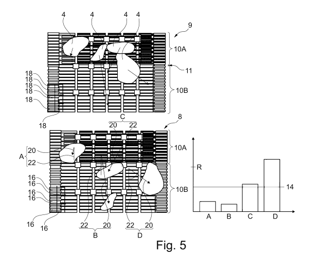
Fig. 5 shows a view of a test image and its partial evaluation,
Fig. 6 shows the test image according to fig. 5 and its further possible
partial
evaluation,
Fig. 7 shows a subject matter according to the invention,
Figs 8 and 9 show the subject matter according to fig. 7 in different side
views,
Fig. 10 shows a partial view of the subject matter according to fig. 7
with a con-
veyor element,
Fig. 11 shows a view of a detail of an area of the device according to
fig. 7
which is partially illustrated in fig. 10,
Fig. 12 shows the subject matter according to fig. 11 from a different
perspec-
tive,
Fig. 13 shows an illustration of the test image of the image-capturing
unit ac-
cording to fig. 11,
Fig. 14 shows a separating device of the machine according to fig. 7 with
an
image-capturing unit,
Date Recue/Date Received 2021-05-05
CA 03118776 2021-05-05
- 39 -
Fig. 15 shows a schematic test image captured from the perspective of the
im-
age-capturing unit shown in fig. 14,
Fig. 16 shows a further separating device of the machine according to
fig. 7
with an image-capturing unit,
Fig. 17 shows a schematically illustrated test image captured from the
perspec-
tive of the image-capturing unit shown in fig. 16,
Fig. 18 shows a further view of a detail of a machine according to fig. 7
with a
further image-capturing unit,
Fig. 19 shows a schematic illustration of a test image considered from
the per-
spective of the image-capturing unit according to fig. 18, and
Fig. 20 shows a view of a detail of a further device according to the
invention.
Identically or similarly acting parts are, where expedient, provided with
identical ref-
erence symbols. Individual technical features of the exemplary embodiments de-
scribed below can also be combined with the features of the exemplary embodi-
ments described above to form developments according to the invention, but
always
Date Recue/Date Received 2021-05-05
CA 03118776 2021-05-05
- 40 -
at least in combination with the features in one of the independent claims.
The sub-
ject matters specified in the list of the figures are in some cases only
illustrated par-
tially in individual figures.
The method according to the invention serves to control the operation of a
machine
2 for harvesting root crop 4 (cf. figs 6 to 8). In the method, at least one
optical image-
capturing unit 6 captures at least one test image 8 which shows harvested
material
comprising root crop 4 which is moved along relative to a machine frame 12 of
the
machine 2 by means of at least one conveyor element which is designated
initially
generally by 10.
The test image 8 is transmitted to an evaluation device which generates, on
the ba-
sis of a test data set which is generated on the basis of the test image 8 or
formed
thereby, a separating device setting signal for setting at least one operating
parame-
ter of a separating device of the machine 2. The representations which are
illustrated
as test images or initial images merely show schematically the parts which are
rele-
vant for the invention without any borders or limitations. Images, in
particular digital
images, which are captured by a camera, comprise, under certain circumstances,
further information which is not illustrated in the representations. This
information
can, for example, already be masked or filtered at the camera or when a test
data
set is produced or processed.
In one exemplary embodiment according to the invention, a crop flow 1.1 of a
sepa-
rating device is captured by means of a first image-capturing unit 6 (block
1.2, fig. 1).
Date Recue/Date Received 2021-05-05
CA 03118776 2021-05-05
-41 -
Moreover, the crop flow of two further optical image-capturing units is
additionally
monitored (blocks 1.3 and 1.4), for example downstream of the outlet of the
separat-
ing device and in the region of a discharge belt for extraneous materials 5,
which are
separated off by means of the separating device. Capacity utilization
characteristic
values LS_1 to LS_3 are determined (blocks 1.5, 1.6, 1.7) for the respective
measur-
ing points or areas captured by the image-capturing units 6 by means of the
method
according to the invention. These values are combined arithmetically in block
1.8,
which gives rise to a conveying speed signal for at least one conveyor element
10 of
the separating device. In this way, the conveying speed of the conveyor
element is
set (block 1.9), which optimizes the crop flow 1.1 in the separating device.
The determination of the conveying speed signal is illustrated in fig. 2 with
a higher
level of detail. Accordingly, a test image 8 comprising harvested material on
a con-
veyor element 10 (block 3, corresponds to block 1.1) is firstly captured by
the image-
capturing unit. After the capturing of the test image 8, according to a first
method se-
quence according to the invention a relevant image section or part of the test
image
8 is extracted by means of corresponding filtering or masking. For this
purpose, a
mask or region of interest (ROI) is predefined on the basis of the position of
the im-
age-capturing unit and is used to differentiate sections of the test image 8
which are
to be taken into account and ones which are not to be taken into account
(block
13.1). A movement characteristic value for a multiplicity of image areas, in
particular
for each pixel of the image section, is calculated on the basis of the
relevant image
section of the test image 8 and of the associated test data set (block 13.2).
The
Date Recue/Date Received 2021-05-05
CA 03118776 2021-05-05
-42 -
movement characteristic value comprises in particular a direction of movement.
Sub-
sequently, the multiplicity of movement characteristic values is evaluated
statistically
(block 13.3). For this purpose, the movement characteristic values are each
com-
pared with assigned reference characteristic values which are provided from a
pref-
erably machine-specific database which can, in particular, be updated (block
13.4),
and a difference between said values is calculated, or the movement
characteristic
values are each compared with a uniform reference characteristic value and a
devia-
tion therefrom is calculated. The movement characteristic values or the
calculated
deviations are evaluated statistically by the evaluation device, in particular
a stand-
ard deviation of the movement characteristic values from the reference
characteristic
values is calculated.
A low-pass filter for smoothing the acquired values subsequently passes via
the con-
tinuously evaluated statistic (block 13.5). A predefined and in particular
predefinable
filter time constant is used for this (block 13.6), which specifies the degree
of
smoothing.
A capacity utilization characteristic value, generally denoted by LS, of the
conveying
line area which is represented in the test image is acquired on the basis of
the fil-
tered or smoothed statistic of the deviations described above (block 13.7).
Said
value represents the movement situation of the harvested material or of the
crop flow
in the region of the separating device, in particular on the conveyor element
or in the
transition region between two conveyor elements.
Date Recue/Date Received 2021-05-05
CA 03118776 2021-05-05
- 43 -
Referring to the second supplementary or alternative path, the relevant test
image
parts are also firstly extracted (block 2.1). For this purpose, a mask or
region of inter-
est (ROI) can be predefined on the basis of the position of the image-
capturing unit 6
(block 2.2) and is used to differentiate distances in the test image 8 which
are to be
taken into account and ones which are not to be taken into account. The
calculation
of portions of the individual image areas showing components of the harvested
ma-
terial is now performed on the basis of the relevant image section of the test
image 8
and of the test data set which is provided for processing (block 2.3). In
particular the
color information can be evaluated for this purpose. These values can be
obtained
from a reference table or else specified by an operator (block 2.4).
The deviations of the calculated portions from the threshold value are
calculated
(block 2.6) on the basis of a threshold value definition (block 2.5). The
threshold
value is, for example, an ideal value for the respectively considered portion
(e.g. root
crop, amount of extraneous material 1, amount of extraneous material 2). Subse-
quently, low-pass filtering is carried out for the purpose of smoothing the
acquired
deviations (block 2.7). In this context, a filter time constant which is
defined accord-
ing to block 2.8 is used. Subsequently, a further capacity utilization
characteristic
value LS or the capacity utilization characteristic value LS is calculated on
the basis
of the smoothed values of the deviations for the individual positions along
the con-
veying line and the respective portions (block 2.9).
Date Recue/Date Received 2021-05-05
CA 03118776 2021-05-05
-44 -
Subsequently, the conveying speed signal will be generated on the basis of the
ca-
pacity utilization characteristic value or values LS, for example by means of
a three-
point controller, described below (block 2.10).
Fig. 3 shows a program sequence diagram of the calculation of the capacity
utiliza-
tion characteristic value LS to form the conveying speed signal. In this
embodiment,
the capacity utilization characteristic value LS has a value of -1, 0 or 1,
and has been
generated as described above. After the start of the method, the device
listens or
waits for a new capacity utilization characteristic value LS (block 14.1). Of
course,
the respective capacity utilization characteristic values which are also all
simply de-
noted here by "LS", have to be differentiated for the purpose of the
programming,
and are therefore denoted by LS_x in figure 3. After the transfer of the
capacity utili-
zation characteristic value, the procedure is continued as a function of the
magnitude
thereof. A capacity utilization characteristic value LS_x of 0 represents a
desired ca-
pacity utilization of the separating device, a capacity utilization
characteristic value of
-1 represents an underload, i.e. excessively low capacity utilization of the
separating
device, and a capacity utilization characteristic value of 1 represents an
overload, i.e.
an excessively high capacity utilization with a risk of blockage. If the
capacity utiliza-
tion characteristic value is 0, this is input into the memory 14.2 of the last
capacity
utilization characteristic values (block 14.3) without a conveying speed
signal for
changing the conveying speed being output. If the capacity utilization
characteristic
value is 1, a previous capacity utilization characteristic value which is
stored in the
memory 14.2 is interrogated (block 14.4) and it is subsequently determined
whether
Date Recue/Date Received 2021-05-05
CA 03118776 2021-05-05
- 45 -
an overload has already been detected after the last stored capacity
utilization char-
acteristic value of 0 (block 14.5). If this is not the case, the evaluation
device outputs
a conveying speed signal for reducing the speed (deceleration signal, block
14.6). If
this is the case, the new capacity utilization characteristic value is input
into the
memory 14.2 and no conveying speed signal (a further one which reduces the con-
veying speed) is output. The speed control according to the invention (block
14.7),
i.e. the adaptation of the conveying speed to the capacity utilization of the
individual
monitored areas of the conveying line or of the separating device, occurs on
the ba-
sis of the conveying speed signal according to block 14.6.
If the capacity utilization characteristic value has a value of -1, a capacity
utilization
characteristic value which is input into the memory 14.2 is in turn
interrogated (block
14.8), and in accordance with the differentiation described above it is
decided
whether a conveying speed signal for accelerating the conveying speed is
output or
has been already output. The program sequence can optionally be optimized by
vir-
tue of the fact that an acceleration is triggered only a specific sequence of
a number
of capacity utilization characteristic values which indicate an underload or
insufficient
loading. Therefore, for example for the respective areas of the conveying line
it is
monitored whether an underload is present (block 14.9), and only then is an
acceler-
ation pulse emitted (block 14.10).
Fig. 4 shows a program sequence diagram of the evaluation of the conveying
speed
signal. In the method sequence shown, a conveying speed increment or decrement
Date Recue/Date Received 2021-05-05
CA 03118776 2021-05-05
-46 -
for changing the conveying speed is calculated (block 17.2) on the basis of
the con-
veying speed signal 17.1. Values such as the degree of the capacity
utilization char-
acteristic value can be input into the calculation on the basis of a rule base
which is
present and can in particular be predefined and varied (block 17.3). Likewise,
for the
calculation of the increment or decrement it can be taken into account whether
the
machine is in a fine control range of the speed, e.g. near to the capacity
utilization
limit (e.g. a difference of less than 10%), or is still in a rough control
range further
away (e.g. more than 50%) from the capacity utilization limit. The capacity
utilization
limit can preferably be defined in the evaluation device as that value
starting from
which an excessively large deviation, which signals blockage of material,
occurs.
The conveying speed increment or decrement is converted by the evaluation
device
into a speed specification for a separating device drive (block 17.5). The
resulting
conveying speed signal is transmitted to the separating device drive (block
17.6).
This results in a conveying speed of the separating device (17.4).
Figures 5 and 6 show, by way of example, the evaluation of individual test
images.
Fig. 5 is a schematic illustration of an initial image 9 and of a test image
8, each with
root crop 4 on a conveying line comprising two conveyor elements 10A and 10B.
In
the text which follows, conveyor elements are generally also denoted by "10"
for the
purpose of simplification. A conveyor element 10 is then one or more conveyor
ele-
ments from the set of conveyor elements (10A, 10B, 100, 10D, ...).
Date Recue/Date Received 2021-05-05
CA 03118776 2021-05-05
- 47 -
In one preferred embodiment of the method according to the invention, the
evalua-
tion device compares the initial image 9 with the test image 8 insofar as
directions of
movement of objects illustrated in the images are determined. An object does
not
necessarily characterize a coherent body but rather in the test image 8 merely
con-
stitutes an area which can be identified in respect of its movement and which
is in
particular of the size of an area which is represented by means of one pixel
of the
test image 8. In particular, in this way the evaluation device therefore
calculates a di-
rection of movement for each pixel of the test image 8, assesses its deviation
from a
reference direction which is known for each area ¨ in particular for each
pixel ¨ and
evaluates these deviations statistically. Fig. 5 shows, by way of example, a
respec-
tive calculated direction of movement, in the form of a simultaneously
displayed vec-
tor for each type of root crop 4, independently of the consideration of the
movement
at the pixel level. Each arrow represents a movement characteristic value 20.
The movement characteristic values 20 are evaluated statistically for the
calculation
of the capacity utilization characteristic value LS. In this context, the
movement char-
acteristic values 20 merely comprise a direction of movement, and not a
movement
distance, indicated for example by the length of the arrow. Fig. 5 also shows
a histo-
gram with one column per movement characteristic value 20. Each column charac-
terizes here an absolute-value deviation of the corresponding movement
characteris-
tic value 20 from a uniform reference characteristic value 22.
Date Recue/Date Received 2021-05-05
CA 03118776 2021-05-05
- 48 -
In order to calculate a capacity utilization characteristic value LS,
indicated by the
line 14, in particular a standard deviation of these movement characteristic
value de-
viations from the reference characteristic value 22 is formed. For this
purpose, in
particular the deviations can in particular be respectively squared and then
summed.
This sum is then divided by the number of movement characteristic values 20,
and
the square root of the quotient resulting therefrom is formed. The value which
is ob-
tained in this way is the capacity utilization characteristic value LS, which
is indicated
by way of example in the illustrated histogram.
In order to calculate the movement characteristic values 20, first image areas
16 of
the test image 8 are advantageously compared with further image areas 18 of
the in-
itial image 9, wherein each image area 16, 18 comprises the same number of
pixels
and is in particular rectangular. For the purpose of simplified illustration,
only a few
exemplary image areas 16, 18 are illustrated in fig. 9. Therefore, a movement
char-
acteristic value 20 is obtained for each image area 16, in particular for each
pixel of
the test image 8.
Depending on the conveying line area, it is possible to determine in the
evaluation
device which capacity utilization brings about a reduction or an increase in
the con-
veying speed. It is therefore possible for example to increase the speed when
there
is a standard deviation of less than 10 , to maintain the speed when there is
a stand-
ard deviation of 10 to 20 , and to reduce the conveying speed when there is a
larger
standard deviation. Accordingly, for the conveyor elements 10A and 10B,
embodying
a drop step between two screening belts, it is possible to determine, on the
basis of
Date Recue/Date Received 2021-05-05
CA 03118776 2021-05-05
- 49 -
the evaluation solely of the detected directions and their standard deviation,
whether
a blockage of harvested material occurs on the conveyor element 10B which is
lo-
cated below. If a corresponding state, owing for example to a threshold value
R indi-
cating a blockage being exceeded, is detected, a conveying speed signal for
accel-
erating the conveyor element 10B is output by the evaluation device, as an
alterna-
tive to or in addition to a reduction in the conveying speed of the inwardly
conveying
conveyor element 10A.
Fig. 6 shows by way of example a test image 8 in the upper part of the figure,
which
image also again shows the transition from the conveyor element 10A to the con-
veyor element 10B. Root crop 4 and extraneous materials 5 which can comprise
stones and weeds are located in this conveying line area. According to the
classifiers
which are defined in the training of the algorithm or specified by means of a
data-
base, for example a table with color values in the HSV format, individual
partial im-
age areas 16 are checked for the presence of identical components. Therefore,
the
assignment of the respective image areas to the individual portions,
illustrated by
way of example bottom left in fig. 5, results in a portion distribution of
individual por-
tions of root crop 4 and extraneous materials 5 in the test image 8. Al
therefore
shows the portion of the root crop 4 in the test image 8 or the corresponding
test
data set, A2 shows the portion of weeds and A3 shows the portion of stones.
This
assignment is preferably made on the basis of the color information,
preferably also
comprising black-and-white and/or gray values of the individual pixels, i.e.
an image
area 19 which is assigned to a portion corresponds in particular to an area of
a pixel.
The capacity utilization characteristic value which is denoted generally by LS
is
Date Recue/Date Received 2021-05-05
CA 03118776 2021-05-05
- 50 -
based by way of example, and also preferably, on a deviation of the first
portion Al
from a threshold value which is again denoted generally by R and indicates an
opti-
mum portion distribution of root crop at the observed location on the
conveying line.
For example, the capacity utilization characteristic value LS is set to 1 when
there is
a deviation 50% from the cleaning threshold value, and to 0 when there is a
devia-
tion of < 50% from the cleaning threshold value. These values are then
correspond-
ingly stored and processed in the further program sequence according to
figures 1 to
4.
An arrangement of the optical image-capturing units 6 is disclosed in fig. 8.
The ma-
chine 2 according to the invention is embodied as a towed potato harvester,
wherein
a multiplicity of conveyor elements 10 and their associated separating devices
are
secured by means of a machine frame 12, which is only partially designated.
Along
the conveying line there are a multiplicity of image-capturing units 6 which
capture
images of the harvested material which is transported on the conveyor elements
10
and comprises root crop 4. The optical image-capturing units 6 form individual
meas-
uring points for monitoring the respective separating devices.
The positions of image-capturing units 6 which are indicated in fig. 7 are an
area di-
rectly after a grubbing device 29 (measuring point MS1), a transition from a
first con-
veyor element 10A in the form of a screening belt to a second conveyor element
10B
in the form of a screening belt which is additionally surrounded by a coarse
weed
belt (measuring point MS2), the transition from this second screening belt 10B
to a
further conveyor element 10C comprising a further separating device (measuring
Date Recue/Date Received 2021-05-05
CA 03118776 2021-05-05
-51 -
point MS3). Moreover, on the output side of this separating device a conveyor
ele-
ment 10E which leads to the sorting table and has a further image-capturing
unit 6
(measuring point MS4) is monitored, wherein at the same time images of a
further
conveyor element 1OF which is provided for residues of extraneous materials 5,
in
particular stones, are captured. Finally, a further optical image-capturing
unit 6
(measuring point MSS) is present at the sorting table 45.
An evaluation device can be positioned at any desired centrally accessible
location,
but preferably in the vicinity of the sorting table. Information relating to
the setting of
the separating devices can be sent to an operator on a tractor vehicle from
the eval-
uation device, for example via a cable 12.1 which can be seen in fig. 7.
The machine 2 which is illustrated in the side view in figs 8 and 9 clarifies
the posi-
tions of the optical image-capturing units 6. In particular, the image-
capturing unit 6
which is located at the sorting table 45 can be arranged directly at a drop
step lead-
ing to a bunker 33.
Figs 10 and 11 show the arrangement of an optical image-capturing unit 6 which
is
arranged on the frame above a first drop step between a conveyor element 10A
and
a conveyor element 10B and whose field of vision is directed downward
(measuring
point 2). A light source 7 ensures that the field of vision is illuminated in
order to cap-
ture a sufficiently lit test image 8. The conveyor element 10A is a screening
belt
which already screens out some of the extraneous materials 5, in particular
earth,
coming from a grubbing device 29 and transfers them to a further conveyor
element
Date Recue/Date Received 2021-05-05
CA 03118776 2021-05-05
- 52 -
10B, embodied as a screening belt, via a drop step. This conveyor element 10B
ad-
ditionally has a coarse weed belt which is provided for separating off the
weeds pre-
sent with the potatoes or in the harvested material. Stripping devices 32 are
corre-
spondingly arranged over the width of the conveyor element 10B.
A height H of the stripping device 32 above the conveying plane of the
conveyor ele-
ment 10B can also be set. The conveying speeds of the conveyor elements 10A
and
10B can be set by means of the method according to the invention. Fig. 11
illustrates
only one coarse weed belt 43, and not the actual conveyor element 10B (cf.
fig. 13),
embodied in the form of a screening belt, for purposes of clarity.
A test image 8 which is obtained from the field of vision of the optical image-
captur-
ing unit 6, which is shown by means of dashes in fig. 12, is illustrated in
detail (with-
out harvested material) in fig. 13. The evaluations described above are made
using a
test data set provided from this test image 8 on the basis of the detected
directions
of movement of the harvested material and/or on the basis of the respective
portions
of the components of harvested material, and when necessary the conveying
speeds
of the conveyor elements are adjusted.
The harvested material which is still present is transferred from the conveyor
ele-
ment 10B to a further conveyor element 10C with a conveying direction 1C. A
sepa-
rating device in the form of a plurality of rotating deflection rollers 24
which are posi-
tioned one above the other is assigned to said further conveyor element 10C.
The
Date Recue/Date Received 2021-05-05
CA 03118776 2021-05-05
- 53 -
harvested material is transported in the direction of the conveyor element 10D
(fig.
14) by means of a pulse which is applied by said separating device.
A distance H between a conveyor element 10C and the lower deflection roller 24
can
be set by the operating personnel for the purpose of varying a separating
perfor-
mance. The speeds of at least the inward conveying conveyor element 10C and
out-
ward conveying conveyor element 10D, which are embodied as screening belts,
can
be varied by means of the method according to the invention. In addition,
according
to one advantageous development the separating performance or deflection can
be
varied by virtue of the adjustability of the circulation speeds of the
deflection rollers
24.
The image-capturing unit 6 illustrated in fig. 14 generates the test image
which is il-
lustrated in fig. 15 and in which a test image part 8A is defined by means of
filtering
or masking. In addition, a test image part 8B, which is located behind the
deflection
rollers 24 when viewed from a conveying direction 1C, is also defined by
filtering.
Therefore, the areas of the conveyor element 10C which are located upstream
and
downstream of the separating element formed by the deflection rollers 24 are
moni-
tored for the setting of the conveying speed. Respective test data sets can be
pro-
duced for the two image areas 8A and 8B, and the respective evaluations for
the two
image areas 8A and 8B can result from the corresponding partial areas of a
test data
set.
Date Recue/Date Received 2021-05-05
CA 03118776 2021-05-05
- 54 -
Insofar as an associated setpoint value for the test image part 8A reveals
accumula-
tion of material upstream of the deflection rollers 24, the conveying speed of
the con-
veyor element 10C is increased.
Alternatively, the evaluation can be based only on the areas 8A and 8C which
are lo-
cated upstream of the deflection rollers 24, are surrounded by dashed lines
and are
adjacent to another. Permissible densities of portions can be defined for
these two
areas, for example by means of the respective threshold values R. Starting
from the
upward transgression of e.g. a portion of, for example, root crop 4 which is
associ-
ated with excessive accumulation directly upstream of the deflection rollers,
the in-
ward conveying belt 10C can be made to run more quickly, and alternatively or
addi-
tionally an outward conveying belt can be made to run more quickly.
A height H of the lower ends of fingers 26 of a separating device which is
embodied
as a finger web 26.1 can also be settable as one of a plurality of operating
parame-
ters by the operating personnel. The height H describes the distance between
the
fingers 26 and the upper edge of the conveyor element which is embodied as a
hedgehog web. Moreover, an attitude angle of the finger web 26.1 can be
configured
in such a way that it can be set with respect to a vertical to the conveying
plane of
the conveyor element. The same applies to the circulation speed of the finger
web
26.1.
A further optical image-capturing unit 6, which is arranged in the area of the
con-
veyor belts 10C and 10D is illustrated in fig. 16. This image-capturing unit 6
can be
Date Recue/Date Received 2021-05-05
CA 03118776 2021-05-05
- 55 -
used, in addition to the image-capturing unit according to fig. 14, to monitor
the
transportation of harvested material in the test image area 8D. In particular,
the im-
age-capturing unit 6 therefore serves to monitor the effect of the separating
and de-
flection device which is embodied by the deflection rollers 24. In particular,
the con-
veying speed of the conveyor element 10D can be adapted as a function of the
re-
sults of the evaluation of the test images 8 of the optical monitoring unit 6
according
to fig. 14. The monitoring unit 6 according to fig. 16 is also assigned a
light source 7
for better illuminating the monitored area 8D.
A further optical image-capturing unit 6 is arranged with an associated light
source 7
above a sorting table with a view of a conveyor element 10E and a conveyor ele-
ment 10F (fig. 18). In this context, as described above, perspective
correction is per-
formed on the basis of the "fisheye" representation of the image-capturing
unit 6. By
means of masking, the test image parts 8A and 8B which are represented in the
test
image 8 according to fig. 19 are selected, and, on the one hand, monitor the
con-
veyor element 10E, as a conveying path, with a conveying direction 1E for
transport-
ing away root crop and, on the other hand, monitor the conveyor element 10F,
as a
further conveying path, with a conveying direction IF for transporting away
extrane-
ous materials 5 in the form of stones. By means of the evaluation described
above it
is checked whether the portions of root crop 4 on the conveyor element 1OF are
too
large. If this is the case, the conveyor element 10D connected upstream is
given a
slower setting by means of the method according to the invention, by means of
the
evaluation device. In addition, in one development of the invention the finger
web
26.1, which is illustrated above the conveyor element 10D embodied as a
hedgehog
Date Recue/Date Received 2021-05-05
CA 03118776 2021-05-05
- 56 -
web, can be adapted with respect to its separating effect as a function of
corre-
sponding control specifications, said finger web 26.1 having fingers 26
(illustrated by
dashed lines by way of example) behind the cover 40 located in front of them.
For
example, the distance between the fingers 26 and the conveyor element 10D is
re-
duced in order to convey away a greater amount of harvested material, in the
form of
root crop 4, onto the conveyor element 10E via an associated chute 41.
Fig. 20 illustrates the arrangement of measuring points MS1 to MSS having
optical
image-capturing units 6 on a schematically illustrated conveying line of a
machine 2
embodied as a beet lifter. The image-capturing units 6 are arranged downstream
of
a grubbing device 29 above a roller table 10M and at the end of a conveyor
element
10N which is embodied as a screening belt (measuring points MS1 and MS2). A
fur-
ther optical image-capturing unit 6 monitors in particular a conveyor element
10P
which is embodied as a screening star (measuring point MS3). The subsequent
con-
veyor element 10Q which is embodied as a screening star is also monitored in
pre-
cisely the same way as a conveyor element lOR which is embodied as a ring
eleva-
tor (measuring points MS4 and MSS). If e.g. a blockage at one of the conveyor
ele-
ments 10M, 10N, 10P, 10Q, 10S is detected, this conveyor element can be made
to
run more quickly at the instigation of the evaluation device. This can be done
accord-
ing to one of a plurality of possible control scenarios, initially only for a
specific time
up to subsequent checking, or can take place until monitoring reveals that the
critical
state has been eliminated.
Date Recue/Date Received 2021-05-05