Note: Descriptions are shown in the official language in which they were submitted.
CA 03119211 2021-05-07
WO 2020/097736
PCT/CA2019/051631
1
APPARATUS AND METHODS FOR MULTI-CHAMBER VAPORIZATION DEVICES
WITH VAPORIZATION SUBSTANCE MIXING
CROSS-REFERENCE TO RELATED APPLICATION
[0001] This application is related to, and claims priority to, United
States Provisional
Patent Application No. 62/768,315, entitled "APPARATUS AND METHODS FOR MULTI-
CHAMBER VAPORIZATION DEVICES WITH VAPORIZATION SUBSTANCE
MIXING", and filed on November 16, 2018, the entire contents of which are
incorporated by
reference herein.
FIELD
[0002] This application relates generally to vaporization devices, and in
particular to
multi-chamber vaporization devices with mixing of vaporization substances
before
vaporization.
BACKGROUND
[0003] A vaporization device is used to vaporize substances for
inhalation. These
substances are referred to herein as vaporization substances, and could
include, for example,
cannabis products, tobacco products, herbs, and/or flavorants. In some cases,
active
substances in cannabis, tobacco, or other plants or materials extracted to
generate concentrates
are used as vaporization substances. These substances could include
cannabinoids from
cannabis, and nicotine from tobacco. In other cases, synthetic substances are
artificially
manufactured. Terpenes are common flavorant vaporization substances and could
be
generated from natural essential oils or artificially.
[0004] Vaporization substances could be in the form of loose leaf in the
case of cannabis,
tobacco, and herbs, for example, or in the form of concentrates or derivative
products such as
liquids, waxes, or gels, for example. Vaporization substances, whether
intended for flavor or
some other effect, could be mixed with other compounds such as propylene
glycol, glycerin,
CA 03119211 2021-05-07
WO 2020/097736
PCT/CA2019/051631
2
medium chain triglyceride (MCT) oil and/or water to adjust the viscosity of a
final
vaporization substance.
[0005] In a vaporization device, the vaporization substance is heated to
the vaporization
point of one or more constituent ingredients or substances. This produces a
vapor, which may
also be referred to as an aerosol. The vapor is then inhaled by a user through
an air channel
that is provided in the vaporization device, and often through a hose or pipe
that is part of or
attached to the vaporization device.
SUMMARY
[0006] Conventional vaporization devices include a single chamber for
storing a
vaporization substance. However, vaporization devices with multiple chambers
for storing
vaporization substances could be desirable. For example, multiple chambers
could include
different vaporization substances for mixing before vaporization.
[0007] According to an aspect of the present disclosure, an apparatus
includes a mixer to
receive and actively mix vaporization substances to form a vaporization
substance mixture;
and an atomizer, in fluid communication with the mixer, to vaporize the
vaporization
substance mixture.
[0008] Such an apparatus could also include chambers to store respective
vaporization
substances.
[0009] A channel in fluid communication with the atomizer could also be
provided in
2 0 such an apparatus.
[0010] In an embodiment, an apparatus also includes a mouthpiece in
fluid
communication with the channel.
[0011] The chambers could include a chamber with an engagement structure
to engage
with a complementary engagement structure of the apparatus.
[0012] At least one of the vaporization substances is a liquid in some
embodiments.
CA 03119211 2021-05-07
WO 2020/097736
PCT/CA2019/051631
3
[0013] In another embodiment, at least one of the vaporization
substances is a dry
substance.
[0014] At least one of the vaporization substances could be a wax.
[0015] The vaporization substances could also or instead include a gel.
[0016] Some embodiments also include regulators to control movement of the
vaporization substances to the mixer. The regulators could include, for
example, any one or
more of: a regulator that includes a wick, a regulator that includes a valve,
a regulator that
includes a pump, and a regulator comprising a mechanical feed structure. An
example of a
mechanical feed structure is a screw conveyor.
[0017] The regulators could provide dosage control for the apparatus.
[0018] An apparatus could also include a power controller to control
power to the
atomizer.
[0019] In some embodiments, the mixer includes a mixing channel to
receive the
vaporization substances.
[0020] The mixer could also or instead include a stirring element. Such a
stirring element
could be or include a stirring element that is driven by an electric motor, a
magnetic stirring
element, or an acoustic stirring element.
[0021] Another aspect of the present disclosure relates to an apparatus
that includes a
mixer to receive vaporization substances and an atomizer, in fluid
communication with the
2 0 mixer, to vaporize a vaporization substance mixture. The mixer includes
multiple mixing
elements to mix the vaporization substances and form the vaporization
substance mixture.
[0022] Embodiments disclosed above and/or elsewhere herein could also or
instead be
implemented in conjunction with an apparatus that includes a multiple-element
mixer. For
example, such an apparatus could also include chambers to store respective
vaporization
CA 03119211 2021-05-07
WO 2020/097736
PCT/CA2019/051631
4
substances. The chambers could include a chamber with an engagement structure
to engage
with a complementary engagement structure of the apparatus.
[0023] A channel in fluid communication with the atomizer could also be
provided in
such an apparatus, and in an embodiment, an apparatus also includes a
mouthpiece in fluid
communication with the channel.
[0024] Some embodiments also include regulators to control movement of
the
vaporization substances to the mixer. The regulators could provide dosage
control for the
apparatus. The regulators could include, for example, any one or more of: a
regulator that
includes a wick, a regulator that includes a valve, a regulator that includes
a pump, and a
1 0 regulator comprising a mechanical feed structure. An example of a
mechanical feed structure
is a screw conveyor.
[0025] An apparatus could also include a power controller to control
power to the
atomizer.
[0026] In some embodiments, the mixer includes a mixing channel to
receive the
vaporization substances.
[0027] The mixing elements of the mixer could include, for example, a
splitter to split a
stream that includes the vaporization substances into multiple streams, and a
combiner
coupled to the splitter to combine the multiple streams.
[0028] In some embodiments, the mixing elements are or include wells.
2 0 [0029] The mixing elements could also or instead include ridges.
[0030] In another embodiment, the mixing elements include grooves.
[0031] The mixing elements could include linear elements and/or helical
elements.
[0032] Methods are also contemplated. For example, according to another
aspect of the
present disclosure, a method involves providing a mixer to receive and
actively mix a plurality
of vaporization substances to form a vaporization substance mixture; and
providing an
CA 03119211 2021-05-07
WO 2020/097736
PCT/CA2019/051631
atomizer to vaporize the vaporization substance mixture. Such a method could
also involve
arranging the atomizer in fluid communication with the mixer.
[0033] In some embodiments, a method includes providing chambers to
store respective
vaporization substances of the plurality of vaporization substances, and could
also involve
5 arranging the chambers in fluid communication with the mixer.
[0034] Other components could also or instead be provided. For example,
a method could
involve providing a channel for fluid communication with the atomizer, and in
some
embodiments providing a mouthpiece for fluid communication with the channel.
[0035] The vaporization substances could also be provided, and could
include any one or
more of: a liquid, a dry substance, a wax, and a gel.
[0036] A method could involve providing regulators to control movement
of the
vaporization substances to the mixer, and in some embodiments arranging the
regulators in
fluid communication with the mixer. The regulators could include any one or
more of: a
regulator comprising a wick, a regulator comprising a valve, a regulator
comprising a pump,
and a regulator comprising a mechanical feed structure.
[0037] In some embodiments, a method involves providing a power
controller to control
power to the atomizer. A method could also involve coupling the power
controller to the
atomizer.
[0038] Regarding the mixer, the mixer could include a mixing channel to
receive the
vaporization substances. The mixer could also or instead include a stirring
element.
Examples of a stirring element include any one or more of: a stirring element
to be driven by
an electric motor, a magnetic stirring element, and an acoustic stirring
element.
[0039] Another method involves providing a mixer to receive and mix a
plurality of
vaporization substances, with the mixer comprising a plurality of mixing
elements to mix the
vaporization substances and form a vaporization substance mixture; and
providing an
atomizer to vaporize the vaporization substance mixture.
CA 03119211 2021-05-07
WO 2020/097736
PCT/CA2019/051631
6
[0040] Such a method could include features disclosed above and/or
elsewhere herein.
For example, a method relating to a multiple-element mixer could also involve
arranging the
atomizer in fluid communication with the mixer.
[0041] In some embodiments, a method relating to a multiple-element
mixer includes
.. providing chambers to store respective vaporization substances of the
plurality of vaporization
substances, and could also involve arranging the chambers in fluid
communication with the
mixer.
[0042] A method relating to a multiple-element mixer could involve
providing a channel
for fluid communication with the atomizer, and in some embodiments providing a
mouthpiece
for fluid communication with the channel.
[0043] The vaporization substances could also be provided, and as
described herein could
include any one or more of: a liquid, a dry substance, a wax, and a gel.
[0044] A method relating to a multiple-element mixer could involve
providing regulators
to control movement of the vaporization substances to the mixer, and in some
embodiments
arranging the regulators in fluid communication with the mixer. The regulators
could include
any one or more of: a regulator comprising a wick, a regulator comprising a
valve, a regulator
comprising a pump, and a regulator comprising a mechanical feed structure.
[0045] In some embodiments, a method relating to a multiple-element
mixer involves
providing a power controller to control power to the atomizer. A method
relating to a
2 0 .. multiple-element mixer could also involve coupling the power controller
to the atomizer.
[0046] A multiple-element mixer could include a mixing channel to
receive the
vaporization substances.
[0047] The mixing elements could include, for example, any of: a
splitter to split a stream
that includes the vaporization substances into a plurality of streams and a
combiner coupled to
the splitter to combine the plurality of streams, wells, ridges, grooves,
linear elements, and
helical elements.
CA 03119211 2021-05-07
WO 2020/097736
PCT/CA2019/051631
7
[0048] Another aspect of the present disclosure relates to a method of
use of an apparatus
as disclosed herein. Such a method could involve initiating supply of a
plurality of
vaporization substances to the mixer; initiating vaporization of the
vaporization substance
mixture by the atomizer to produce vapor; and inhaling the vapor.
[0049] According to a further aspect of the present disclosure, a method
involves initiating
supply of a plurality of vaporization substances to a mixer for active mixing
of the
vaporization substances to form a vaporization substance mixture; initiating
vaporization of
the vaporization substance mixture by an atomizer to produce vapor; and
inhaling the vapor.
[0050] A similar method relating to a different type of mixer could
involve initiating
1 0 supply of a plurality of vaporization substances to a mixer that
comprises a plurality of mixing
elements to mix the vaporization substances and form a vaporization substance
mixture;
initiating vaporization of the vaporization substance mixture by an atomizer
to produce vapor;
and inhaling the vapor.
[0051] Other aspects and features of embodiments of the present
disclosure will become
apparent to those ordinarily skilled in the art upon review of the following
description.
BRIEF DESCRIPTION OF THE DRAWINGS
[0052] For a more complete understanding of the present disclosure,
reference is now
made to the following description taken in conjunction with the accompanying
drawings, in
which:
2 0 [0053] Fig. 1 is a plan view of an example vaporization device;
[0054] Fig. 2 is an isometric view of the vaporization device in Fig. 1;
[0055] Fig. 3 is an isometric and partially exploded view of an example
multi-chamber
vaporization device;
[0056] Fig. 4 is a cross-sectional view of the example multi-chamber
vaporization device
of Fig. 3, along line A--A in Fig. 3;
CA 03119211 2021-05-07
WO 2020/097736
PCT/CA2019/051631
8
[0057] Fig. 5 is a block diagram of an example vaporization device that
enables mixing of
multiple vaporization substances prior to vaporization;
[0058] Fig. 6A is a block diagram of an example stirring element
according to an
embodiment;
[0059] Fig. 6B is a block diagram of an example stirring element according
to another
embodiment;
[0060] Fig. 7A is a cross-sectional view of a passive mixing channel
according to an
embodiment;
[0061] Fig. 7B is a cross-sectional view of a passive mixing channel
according to another
embodiment;
[0062] Fig. 7C is a cross-sectional view of a passive mixing channel
according to yet
another embodiment;
[0063] Fig. 7D is a cross-sectional view of a passive mixing channel
according to a further
embodiment;
[0064] Fig. 8 is an isometric view of a multi-chamber cartridge according
to an
embodiment;
[0065] Fig. 9 is an isometric and partially exploded view of the multi-
chamber cartridge
of Fig. 8;
[0066] Fig. 10 is a plan view of the multi-chamber cartridge of Fig. 8;
2 0 [0067] Fig. 11 is a top view of the multi-chamber cartridge of
Fig. 8;
[0068] Fig. 12 is a cross-sectional view of the example multi-chamber
cartridge of Fig. 8,
along line B--B in Fig. 11;
CA 03119211 2021-05-07
WO 2020/097736
PCT/CA2019/051631
9
[0069] Fig. 13 is a cross-sectional and partially exploded view of an
example of
engagement structures in the multi-chamber cartridge of Fig. 8, along a part
of line B--B in
Fig. 11;
[0070] Fig. 14 is a flow diagram illustrating a method according to an
embodiment;
[0071] Fig. 15 is a flow diagram illustrating a method according to another
embodiment.
DETAILED DESCRIPTION
[0072] For illustrative purposes, specific example embodiments will be
explained in
greater detail below in conjunction with the figures. It should be
appreciated, however, that
the present disclosure provides many applicable concepts that can be embodied
in any of a
wide variety of specific contexts. The specific embodiments discussed are
merely illustrative
and do not limit the scope of the present disclosure. For example, embodiments
could include
additional, different, or fewer features than shown in the drawings. The
figures are also not
necessarily drawn to scale.
[0073] The present disclosure relates, in part, to vaporization devices
for vaporization
substances that include active ingredients or substances such as one or more
cannabinoids or
nicotine. However, the vaporization devices described herein could also or
instead be used for
vaporization substances without an active ingredient or substance. As used
herein, the term
"cannabinoid" is generally understood to include any chemical compound that
acts upon a
cannabinoid receptor. Cannabinoids could include endocannabinoids (produced
naturally by
humans and animals), phytocannabinoids (found in cannabis and some other
plants), and
synthetic cannabinoids (manufactured artificially).
[0074] Examples of phytocannabinoids include, but are not limited to,
cannabigerolic acid
(CBGA), cannabigerol (CBG), cannabigerol monomethylether (CBGM),
cannabigerovarin
(CBGV), cannabichromene (CB C), cannabichromevarin (CB CV), cannabidiol (CBD),
cannabidiol monomethylether (CBDM), cannabidiol-C4 (CBD-C4), cannabidivarin
(CBDV),
cannabidiorcol (CBD-C1), delta-9-tetrahydrocannabinol (A9-THC), delta-9-
tetrahydrocannabinolic acid A (THCA-A), delta-9-tetrahydrocannabionolic acid B
(THCA-B),
CA 03119211 2021-05-07
WO 2020/097736
PCT/CA2019/051631
delta-9-tetrahydrocannabinolic acid-C4 (THCA-C4), delta-9-tetrahydrocannabinol-
C4, delta-
9-tetrahydrocannabivarin (THCV), delta-9-tetrahydrocannabiorcol (THC-C1),
delta-7-cis-iso
tetrahydrocannabivarin, delta-8-tetrahydrocannabinol (A8-THC), cannabicyclol
(CB L),
cannabicyclovarin (CBLV), cannabielsoin (CBE), cannabinol (CBN), cannabinol
methylether
5 (CBNM), cannabinol-C4 (CBN-C4), cannabivarin (CBV), cannabinol-C2 (CBN-
C2),
cannabiorcol (CBN-C1), cannabinodiol (CBND), cannabinodivarin (CBVD),
cannabitriol
(CBT), 10-ethoxy-9hydroxy-delta-6a-tetrahydrocannabinol, 8,9-dihydroxy-delta-
6a-
tetrahydrocannabinol, cannabitriolvarin (CBTV), ethoxy-cannabitriolvarin
(CBTVE),
dehydrocannabifuran (DCBF), cannabifuran (CBF), cannabichromanon (CBCN),
10 cannabicitran (CBT), 10-oxo-delta-6a-tetrahydrocannabionol (OTHC), delta-
9-cis-
tetrahydrocannabinol (cis-THC), 3,4,5,6-tetrahydro-7-hydroxy-alpha-alpha-2-
trimethy1-9-n-
propy1-2, 6-methano-2H-1-benzoxocin-5-methanol (OH-iso-HHCV), cannabiripsol
(CBR),
trihydroxy-delta-9-tetrahydrocannabinol (tri0H-THC), cannabinol propyl variant
(CBNV),
and derivatives thereof.
[0075] Examples of synthetic cannabinoids include, but are not limited to,
naphthoylindoles, naphthylmethylindoles, naphthoylpyrroles,
naphthylmethylindenes,
phenylacetylindoles, cyclohexylphenols, tetramethylcyclopropylindoles,
adamantoylindoles,
indazole carboxamides, and quinolinyl esters.
[0076] A cannabinoid may be in an acid form or a non-acid form, the
latter also being
2 0 .. referred to as the decarboxylated form since the non-acid form can be
generated by
decarboxylating the acid form. Within the context of the present disclosure,
where reference
is made to a particular cannabinoid, the cannabinoid can be in its acid or non-
acid form, or be
a mixture of both acid and non-acid forms.
[0077] A vaporization substance may comprise a cannabinoid in its pure
or isolated form
or a source material comprising the cannabinoid. Examples of source materials
comprising
cannabinoids include, but are not limited to, cannabis or hemp plant material
(e.g, flowers,
seeds, trichomes, and kief), milled cannabis or hemp plant material, extracts
obtained from
cannabis or hemp plant material (e.g., resins, waxes and concentrates), and
distilled extracts or
kief. In some embodiments, pure or isolated cannabinoids and/or source
materials comprising
CA 03119211 2021-05-07
WO 2020/097736
PCT/CA2019/051631
11
cannabinoids may be combined with water, lipids, hydrocarbons (e.g., butane),
ethanol,
acetone, isopropanol, or mixtures thereof.
[0078] In some embodiments, the cannabinoid is tetrahydrocannabinol
(THC). THC is
only psychoactive in its decarboxylated state. The carboxylic acid form (THCA)
is non-
psychoactive. Delta-9-tetrahydrocannabinol (A9-THC) and delta-8-
tetrahydrocannabinol (A8-
THC) produce the effects associated with cannabis by binding to the CB1
cannabinoid
receptors in the brain.
[0079] In some embodiments, the cannabinoid is cannabidiol (CBD). The
terms
"cannabidiol" or "CBD" are generally understood to refer to one or more of the
following
compounds, and, unless a particular other stereoisomer or stereoisomers are
specified,
includes the compound "A2-cannabidiol." These compounds are: (1) A5-
cannabidiol (2-(6-
isopropeny1-3-methy1-5-cyclohexen-l-y1)-5-penty1-1,3-benzenediol); (2) A4-
cannabidiol (2-
(6-isopropeny1-3-methy1-4-cyclohexen-l-y1)-5-penty1-1,3-benzenediol); (3) A3-
cannabidiol
(2-(6-isopropeny1-3-methyl-3-cyclohexen-l-y1)-5-penty1-1,3-benzenediol); (4)
A3,7-
cannabidiol (2-(6-isopropeny1-3-methylenecyclohex-1-y1)-5-penty1-1,3-
benzenediol); (5) A2-
cannabidiol (2-(6-isopropeny1-3-methy1-2-cyclohexen-l-y1)-5-penty1-1,3-
benzenediol); (6) Al-
cannabidiol (2-(6-isopropeny1-3-methyl-l-cyclohexen-l-y1)-5-penty1-1,3-
benzenediol); and (7)
A6-cannabidiol (2-(6-isopropeny1-3-methyl-6-cyclohexen-l-y1)-5-penty1-1,3-
benzenediol).
[0080] In some embodiments, the cannabinoid is a mixture of
tetrahydrocannabinol
(THC) and cannabidiol (CBD). The w/w ratio of THC to CBD a the vaporization
substance
may be about 1:1000, about 1:900, about 1:800, about 1:700, about 1:600, about
1:500, about
1:400, about 1:300, about 1:250, about 1:200, about 1:150, about 1:100, about
1:90, about
1:80, about 1:70, about 1:60, about 1:50, about 1:45, about 1:40, about 1:35,
about 1:30, about
1:29, about 1:28, about 1:27, about 1:26, about 1:25, about 1:24, about 1:23,
about 1:22, about
1:21, about 1:20, about 1:19, about 1:18, about 1:17, about 1:16, about 1:15,
about 1:14, about
1:13, about 1:12, about 1:11, about 1:10, about 1:9, about 1:8, about 1:7,
about 1:6, about 1:5,
about 1:4.5, about 1:4, about 1:3.5, about 1:3, about 1:2.9, about 1:2.8,
about 1:2.7, about
1:2.6, about 1:2.5, about 1:2.4, about 1:2.3, about 1:2.2, about 1:2.1, about
1:2, about 1:1.9,
about 1:1.8, about 1:1.7, about 1:1.6, about 1:1.5, about 1:1.4, about 1:1.3,
about 1:1.2, about
CA 03119211 2021-05-07
WO 2020/097736
PCT/CA2019/051631
12
1:1.1, about 1:1, about 1.1:1, about 1.2:1, about 1.3:1, about 1.4:1, about
1.5:1, about 1.6:1,
about 1.7:1, about 1.8:1, about 1.9:1, about 2:1, about 2.1:1, about 2.2:1,
about 2.3:1, about
2.4:1, about 2.5:1, about 2.6:1, about 2.7:1, about 2.8:1, about 2.9:1, about
3:1, about 3.5:1,
about 4:1, about 4.5:1, about 5:1, about 6:1, about 7:1, about 8:1, about 9:1,
about 10:1, about
11:1, about 12:1, about 13:1, about 14:1, about 15:1, about 16:1, about 17:1,
about 18:1, about
19:1, about 20:1, about 21:1, about 22:1, about 23:1, about 24:1, about 25:1,
about 26:1, about
27:1, about 28:1, about 29:1, about 30:1, about 35:1, about 40:1, about 45:1,
about 50:1, about
60:1, about 70:1, about 80:1, about 90:1, about 100:1, about 150:1, about
200:1, about 250:1,
about 300:1, about 400:1, about 500:1, about 600:1, about 700:1, about 800:1,
about 900:1, or
about 1000:1.
[0081] In some embodiments, a vaporization substance may include
products of
cannabinoid metabolism, including 11-hydroxy-A9-tetrahydrocannabinol (11-0H-
THC).
[0082] These particulars of cannabinoids are intended solely for
illustrative purposes.
Other embodiments are also contemplated.
[0083] Fig. 1 is a plan view of an example vaporization device 100. In Fig.
1, the
vaporization device 100 is viewed from the side. The vaporization device 100
could also be
referred to as a vaporizer, a vaporizer pen, a vape pen or an electronic or "e-
" cigarette, for
example. The vaporizer 100 includes a cap 102, a chamber 104, a base 106 and a
battery
compartment 108.
2 0 [0084] The cap 102 is an example of a lid or cover, and includes a
tip 112 and sidewalls
114 and 115, which could be sides or parts of the same cylindrical sidewall in
some
embodiments. The cap 102, in addition to sealing an end of an interior space
of the chamber
104, could also provide a mouthpiece through which a user can draw vapor from
the
vaporization device 100. The mouthpiece could be tapered, as shown, or
otherwise shaped for
a user's comfort. The present disclosure is not limited to any particular
shape of the cap 102.
CA 03119211 2021-05-07
WO 2020/097736
PCT/CA2019/051631
13
[0085] The cap 102 could be made from one or more materials including
metals, plastics,
elastomers and ceramics, for example. However, other materials could also or
instead be
used.
[0086] In other embodiments, the mouthpiece could be separate from the
cap. For
example, the cap could be connected to the mouthpiece by a hose or pipe. The
hose or pipe
could accommodate the flow of vapor from the cap to the mouthpiece. The hose
or pipe could
also be flexible, allowing a user to orient the mouthpiece independently from
the cap.
[0087] The chamber 104 is an example of a vessel to store a vaporization
substance prior
to vaporization. Although embodiments are described herein primarily in the
context of
1 0 vaporization liquids such as oil concentrates, in general a chamber may
store other forms of
vaporization substances, including waxes and gels, for example. Vaporization
substances
with water-based carriers are also contemplated. A vaporization device could
be capable of
vaporizing water-based carriers with emulsified cannabinoids, for example. In
some
embodiments, chambers could contain dry vaporization substances. The chamber
104 could
also be referred to as a container, a housing or a tank.
[0088] The chamber 104 includes outer walls 118 and 120. The outer walls
118 and 120
of the chamber 104 could be made from one or more transparent or translucent
materials, such
as tempered glass or plastics, in order to enable a user to visibly determine
the quantity of
vaporization substance in the chamber. The outer walls 118 and 120 could
instead be made
2 0 from one or more opaque materials such as metal alloys, plastics or
ceramics, to protect the
vaporization substance from degradation by ultraviolet radiation, for example.
The outer
walls 118 and 120 of the chamber 104 could include markings to aid the user in
determining
the quantity of vaporization liquid in the chamber. The chamber 104 could be
any of a
number of different heights. Although multiple outer walls are shown in Fig. 1
at 118 and
120, the chamber 104 is perhaps most often cylindrical, with a single outer
wall.
[0089] The chamber 104 engages the cap 102, and could be coupled to the
cap, via an
engagement or connection at 116. A gasket or other sealing member could be
provided
between the chamber 104 and the cap 102 to seal the vaporization substance in
the chamber.
CA 03119211 2021-05-07
WO 2020/097736
PCT/CA2019/051631
14
[0090] Some chambers are "non-recloseable" or "disposable" and cannot be
opened after
initial filling. Such chambers are permanently sealed once closed. Others are
recloseable
chambers in which the engagement at 116, between the cap 102 and the chamber
104, is
releasable. For example, the cap 102 could be a cover that releasably engages
the chamber
104 and seals a vaporization substance in the chamber 104. A releasable
engagement could
include, for example, a threaded engagement or other type of connection, or an
abutment
between the chamber 104 and the cap 102, without necessarily an actual
connection between
the chamber and the cap. Such a releasable engagement permits the cap 102 to
be disengaged
or removed from the chamber 104 so that the chamber can be cleaned, emptied,
and/or filled
1 0 with a vaporization substance, for example. The cap 102 could then re-
engage with the
chamber 104 to seal the vaporization substance inside the chamber.
[0091] Fig. 1 also illustrates a stem 110 inside the chamber 104. The
stem 110 is a hollow
tube or channel through which vapor can be drawn into and through cap 102. The
stem 110
may also be referred to as a central column, a central post, a chimney, a hose
or a pipe. The
stem 110 includes outer walls 122 and 124, although in many embodiments the
stem will
likely be cylindrical, with a single outer wall. Materials such as stainless
steel, other metal
alloys, plastics and ceramics could be used for stems such as the stem 110.
The stem 110
couples the cap 102 via an engagement or connection 126. Similar to the
engagement or
connection 116, the engagement or connection 126 could be a releasable
engagement or
2 0 connection that includes a releasable engagement between the stem 110
and the cap 102. In
some embodiments, the engagement 126 is in the form of, or includes, a
releasable
connection.
[0092] Although labeled separately in Fig. 1, the engagements at 116 and
126 are
operationally related in some embodiments. For example, screwing the cap 102
onto the stem
110 could also engage the cap with the chamber 104, or similarly screwing the
cap onto the
chamber could also engage the cap with the stem.
[0093] An atomizer 130 is provided at the base of the stem 110 inside
the chamber 104.
The atomizer 130 may also be referred to as a heating element, a core, or a
ceramic core. The
atomizer 130 includes sidewalls 131 and 133, which could actually be a single
cylindrical or
CA 03119211 2021-05-07
WO 2020/097736
PCT/CA2019/051631
frustoconical wall in some embodiments, and one or more wicking holes or
intake holes, one
of which is shown at 134. The sidewalls of the atomizer 130 could be made from
a metal
alloy such as stainless steel, for example. The sidewalls 131 and 133 of the
atomizer 130
could be made from the same material as the stem 110, or from different
materials.
5 [0094] The atomizer 130 engages, and could couple with, the stem
110 via an engagement
132, and with the base 106 via an engagement 136. Although the engagements 132
and 136
could be releasable, the stem 110, the atomizer 130, and the base 106 could be
permanently
attached together. The atomizer sidewalls 131 and 133 could even be formed
with the stem
110 as an integrated single physical component.
10 [0095] In general, the atomizer 130 converts the vaporization
substance in the chamber
104 into a vapor, which a user draws from the vaporization device 100 through
the stem 110
and the cap 102. Vaporization liquid, for example, could be drawn into the
atomizer 130
through the wicking hole 134 and a wick. The atomizer 130 could include a
heating element,
such as a resistance coil around a ceramic wick, to perform the conversion of
vaporization
15 liquid into vapor. A ceramic atomizer could have an integrated heating
element such as a
coiled wire inside the ceramic, similar to rebar in concrete, in addition to
or instead of being
wrapped in a coiled wire.
[0096] In some embodiments, the combination of the atomizer 130 and the
chamber 104
is referred to as a cartomizer.
[0097] The base 106 supplies power to the atomizer 130, and may also be
referred to as an
atomizer base. The base 106 includes sidewalls 138 and 139, which could be a
single
sidewall such as a cylindrical sidewall. The base 106 engages, and could also
be coupled to
the chamber 104 via an engagement 128. The engagement 128 could be a fixed
connection.
However, in some embodiments, the engagement 128 is a releasable engagement,
and the
base 106 could be considered a form of a cover that releasably engages the
chamber 104 and
seals a vaporization substance in the chamber 104. In such embodiments, the
engagement 128
could include a threaded engagement, a threaded connection, or an abutment
between the
chamber 104 and the base 106, for example. A gasket or other sealing member
could be
CA 03119211 2021-05-07
WO 2020/097736
PCT/CA2019/051631
16
provided between the chamber 104 and the base 106 to seal the vaporization
substance in the
chamber. Such a releasable engagement enables removal or disengagement of the
base 106
from the chamber 104 to permit access to the interior of the chamber, so that
the chamber can
be emptied, cleaned, and/or filled with a vaporization substance, for example.
The base 106
could then re-engage with the chamber 104 to seal the vaporization substance
inside the
chamber.
[0098] The base 106 generally includes circuitry to supply power to the
atomizer 130.
For example, the base 106 could include electrical contacts that connect to
corresponding
electrical contacts in the battery compartment 108. The base 106 could further
include
electrical contacts that connect to corresponding electrical contacts in the
atomizer 130. The
base 106 could reduce, regulate or otherwise control the power/voltage/current
output from
the battery compartment 108. However, this functionality could also or instead
be provided
by the battery compartment 108 itself. The base 106 could be made from one or
more
materials including metals, plastics, elastomers and ceramics, for example, to
carry or
otherwise support other base components such as contacts and/or circuitry.
However, other
materials could also or instead be used.
[0099] The combination of a cap 102, a chamber 104, a stem 110, an
atomizer 130, and a
base 106 is often referred to as a cartridge or "cart".
[00100] The battery compartment 108 could also be referred to as a battery
housing. The
battery compartment 108 includes sidewalls 140 and 141, a bottom 142 and a
button 144. The
sidewalls 140 and 141, as noted above for other sidewalls, could be a single
wall such as a
cylindrical sidewall. The battery compartment 108 engages, and could also
couple to, the
base 106 via an engagement 146. The engagement 146 could be a releasable
engagement
such as a threaded connection or a magnetic connection, to provide access to
the inside of the
battery compartment 108. The battery compartment 108 could include single-use
batteries or
rechargeable batteries such as lithium-ion batteries. A releasable engagement
146 enables
replacement of single-use batteries and/or removal of rechargeable batteries
for charging, for
example. In some embodiments, rechargeable batteries could be recharged by an
internal
battery charger in the battery compartment 108 without removing them from the
vaporization
CA 03119211 2021-05-07
WO 2020/097736
PCT/CA2019/051631
17
device 100. A charging port (not shown) could be provided in the bottom 142 or
a sidewall
140, 141, for example. The battery compartment 108 could be made from the same
material(s) as the base 106 or from one or more different materials.
[00101] The button 144 is one example of a user input device, which could be
implemented
in any of various ways. Examples include a physical or mechanical button or
switch such as a
push button. A touch sensitive element such as a capacitive touch sensor could
also or instead
be used. A user input device need not necessarily require movement of a
physical or
mechanical element.
[00102] Although shown in Fig. 1 as a closed or flush engagement, the
engagement 146
between the base 106 and the battery compartment 108 need not necessarily be
entirely
closed. A gap between outer walls of the base 106 and the battery compartment
108 at the
engagement 146, for example, could provide an air intake path to one or more
air holes or
apertures in the base that are in fluid communication with the interior of the
stem 110. An air
intake path could also or instead be provided in other ways, such as through
one or more
apertures in a sidewall 138, 139, elsewhere in the base 106, and/or in the
battery compartment
108. When a user draws on a mouthpiece, air could be pulled through the air
intake path into
the stem 110, to mix with vapor formed by the atomizer 130.
[00103] The battery compartment 108 powers the vaporization device 100 and
allows
powered components of the vaporization device, including at least the atomizer
130, to
operate. Other powered components could include, for example, one or more
light-emitting
diodes (LEDs), speakers and/or other indicators of device power status (on /
off), device usage
status (on when a user is drawing vapor), etc. In some embodiments, speakers
and/or other
audible indicators could produce long, short, or intermittent "beep" sounds as
a form of
indicator of different conditions. Haptic feedback could also or instead be
used to provide
status or condition indicators. Varying vibrations and/or pulses, for example,
could indicate
different statuses or actions in a vaporization device, such as on/off,
currently vaporizing,
power source connected, etc. Haptic feedback could be provided using small
electric motors
as in devices such as mobile phones, other electrical and/or mechanical means,
or even
magnetic means such as one or more controlled electronic magnets.
CA 03119211 2021-05-07
WO 2020/097736
PCT/CA2019/051631
18
[00104] As noted above, in some embodiments, the cap 102, the chamber 104, the
stem
110, the atomizer 130, the base 106 and/or the battery compartment 108 are
cylindrical in
shape or otherwise shaped in a way such that sidewalls that are separately
labeled in Fig. 1
could be formed by a single sidewall. In these embodiments, the sidewalls 114
and 115
represent sides of the same sidewall. Similar comments apply to outer walls
118 and 120,
sidewalls 131 and 133, outer walls 122 and 124, sidewalls 138 and 139,
sidewalls 140 and
141, and other walls that are shown in other drawings and/or described herein.
However, in
general, caps, chambers, stems, atomizers, bases and/or battery compartments
that are not
cylindrical in shape are also contemplated. For example, these components
could be
rectangular, triangular, or otherwise shaped.
[00105] Fig. 2 is an isometric view of the vaporization device 100. In Fig. 2,
the cap 102,
the chamber 104, the stem 110, the atomizer 130, the base 106, and the battery
compartment
108 are illustrated as being cylindrical in shape. However, as noted above,
this is not
necessarily the case in other vaporization devices. Fig. 2 also illustrates a
hole 150 through
the tip 112 in the cap 102. The hole 150 could be coupled to the stem 110
through a channel
in the cap 102. The hole 150 allows a user to draw vapor through the cap 102.
In some
embodiments, a user operates the button 144 to vaporize a vaporization
substance. Other
vaporization devices could be automatically activated to supply power from the
battery
compartment 108 to powered components of the vaporization device when a user
inhales
through the hole 150. In such embodiments, a button 144 need not be operated
to use a
vaporization device, and need not necessarily even be provided.
[00106] Fig. 3 is an isometric and partially exploded view of an example multi-
chamber
vaporization device, and Fig. 4 is a cross-sectional view of the example multi-
chamber
vaporization device along line A--A in Fig. 3. The vaporization device 300 has
a multi-part
body, with a main body 302 and a removable cover 304. The main body 302 and
the cover
304 could be made from the same material(s) or different materials, including
one or more of
metals, plastics, elastomers and ceramics, for example. However, other
materials could also
or instead be used.
CA 03119211 2021-05-07
WO 2020/097736
PCT/CA2019/051631
19
[00107] The main body 302 and the cover 304 include compartments to receive
vaporization substance chambers 312 and a channel 310. The compartments in the
main body
302 are shown at 311, 313 in Fig. 4, and the cover 304 also includes such
compartments. The
cover 304 tapers at 306 to a mouthpiece 308 in the example shown, and the
mouthpiece is in
fluid communication with the channel 310. The main body 302 could at least
partially carry
or otherwise support components such as the channel 310 and the chambers 312
as shown,
and other components such as one or more batteries, electrical contacts,
and/or circuitry.
Similarly, the cover 304 could at least partially carry or otherwise support
components such as
the channel 310 and the chambers 312, as well as the mouthpiece 308.
[00108] Various channels such as the channel 310 enable fluid flow through a
vaporization
apparatus such as a vaporization device, or at least parts thereof. Such fluid
may include air,
at an intake side of an atomizer for example, or a mixture of air and vapor
upstream of an
atomizer when the atomizer is operating to vaporize a vaporization substance.
Fluid flow
channels may also be referred to as air channels, but are referenced herein
primarily as
channels.
[00109] The mouthpiece 308 could be made from the same material(s) as the
remainder of
the cover 304, and could even be integrated with the cover. In the embodiment
shown, the
mouthpiece 308 engages with the remainder of the cover 304 at an engagement or
connection
309. This engagement or connection 309 could be fixed, which might be
preferable in
2 0 embodiments in which the mouthpiece 308 is cylindrical as shown. In
other embodiments, a
rotatable or otherwise movable engagement or connection 309 might be
preferred, so that a
user can position the mouthpiece 308 in any preferred orientation relative to
the main body
302 and/or the remainder of the cover 304.
[00110] Materials such as stainless steel, other metal alloys, plastics
and ceramics could be
used for the channel 310.
[00111] The chambers 312 could be made, at least in part, from one or more
materials such
as tempered glass, plastics, metal alloys, and/or ceramics. The chambers 312
could be
CA 03119211 2021-05-07
WO 2020/097736
PCT/CA2019/051631
substantially similar to chamber 104 shown by way of example in Figs. 1 and 2,
and could be
coupled to other parts that are made from different materials.
[00112] The cover 304 is removable or releasable from the main body 302. In
the example
shown in Fig. 3, a tab 314 on the cover 304 could be provided with a
protrusion on its inner
5 surface, to engage with a groove or slot 316 in the main body 302 when
the vaporization
device 300 is assembled or closed. This is an example of a releasable
engagement between
the main body 302 and the cover 304. The cover 304 could be removed, to
install or remove
chambers 312 and/or for cleaning the device 300 for example, by pulling the
cover 304 away
from the main body 302 with sufficient force to release the protrusion on the
tab 314 from the
10 slot or groove 316. Removal of the cover 304 in the embodiment shown
could also or instead
involve prying the tab 314 away from the slot or groove 316 to release the tab
protrusion and
allow the cover to be removed.
[00113] The main body 302 could include a structure 318 to accommodate the tab
314, so
that the outer surface of the tab is flush with the outer surface of the main
body when the
15 device 300 is assembled. The structure 318 could be larger than the tab
314 in some
embodiments, to provide clearance for a user to insert a fingernail or tool to
pry the tab away
from the slot or groove 316 when the cover 304 is to be removed.
[00114] In operation, one or more batteries inside the main body 302 provide
power to one
or more atomizers, which vaporize a mixture of vaporization substances from
multiple
20 chambers 312. Any of various arrangements or implementations are
possible, and examples
are disclosed herein.
[00115] It should be appreciated, however, that the example device 300 is
solely for the
purpose of illustration. Other embodiments are also contemplated. For example,
the channel
310 need not be a separate component, and could be integrated or integral with
the main body
302 and/or the cover 304. The channel 310 and/or the chambers 312 could be
accommodated
entirely within the main body 302, in which case the cover 304 need not
include
compartments to receive part of each chamber. Compartments could be
implemented in any
of various ways, and not only as the bores shown at 311, 313 in Fig. 4.
Multiple engagement
CA 03119211 2021-05-07
WO 2020/097736
PCT/CA2019/051631
21
structures such as the tab 314 and the slot or groove 316 could be provided.
Other types of
connection or engagement between a main body and a cover, such as a magnetic
connection,
are also possible. Different shapes or layouts could be implemented, to have a
central channel
with compartments or structures to accommodate chambers around the central
channel, for
example. A multi-chamber vaporization device with a hexagonal cross-sectional
shape, for
example, could accommodate six cartridges or chambers around a central air
channel or
mixing channel. At least certain shapes could be suitable for other types of
releasable
engagement between a main body and a cover, such as a threaded engagement for
a
cylindrical vaporization device.
[00116] With multiple vaporization substances available in a multi-chamber
vaporization
device, more than one vaporization substance could be vaporized for
inhalation. For example,
as disclosed herein, multiple vaporization substances could be mixed to form a
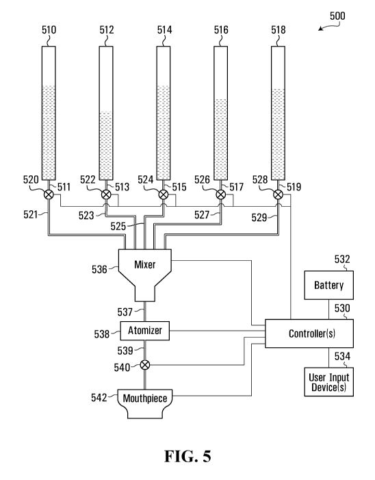
vaporization
substance mixture, with that mixture then being vaporized by an atomizer. Fig.
5 is a block
diagram of an example vaporization device that enables mixing of multiple
vaporization
substances prior to vaporization.
[00117] The example device 500 includes multiple chambers 510, 512, 514, 516,
518 to
store respective vaporization substances. Examples of vaporization substances
and how
vaporization substance chambers could be implemented are disclosed elsewhere
herein.
Vaporization substances could have any of various effects. For example, some
vaporization
2 0 substances could include one or more active ingredients that have a
psychoactive effect,
whereas others could include flavorants such as terpenes. Some vaporization
substances
could include an antidote for an active ingredient or substance in another
vaporization
substance. CBD is one example of an antidote to an active ingredient or
substance in the form
of THC. Other antidotes and active ingredients or substances are also
possible. In general, an
antidote as referenced herein is intended to encompass a substance that may
reduce, reverse,
or otherwise counteract one or more effects of an active ingredient or
substance. An antidote
could also or instead include, for example, a substance that could interfere
with a cannabinoid
receptor such as the CB1 receptors and/or CB2 receptors.
CA 03119211 2021-05-07
WO 2020/097736
PCT/CA2019/051631
22
[00118] Valves 520, 522, 524, 526, 528 in the device 500 are examples of
regulators in
fluid communication with respective chambers 510, 512, 514, 516, 518, through
channels
511, 513, 515, 517, 519, to control movement of the vaporization substances
from the
respective chambers to a mixer 536. The mixer 536 is in fluid communication
with the valves
520, 522, 524, 526, 528 through channels 521, 523, 525, 527, 529 in the
embodiment shown.
Other forms of regulator include, for example, wicks, pumps, and mechanical
feed structures
such as screw conveyors. A vaporization device could include regulators of
different types.
Not all types of regulator are necessarily separately controlled. A wick, for
example, draws a
vaporization substance from a chamber to an atomizer for vaporization, but the
wick itself is
.. not controlled.
[00119] Regardless of the type(s) of regulators in a multi-chamber device, the
regulators
may be useful in providing a measure of dosage control. Different vaporization
substances
could have different levels of active ingredients, and overall dosage of
active ingredients in a
mixture of vaporization substances could be controlled by controlling the
regulators.
.. [00120] Any or all of the valves 520, 522, 524, 526, 528 in the device 500
could be
controlled, for example, by one or more user input devices 534. The user input
devices 534
could include switches, sliders, dials, and/or other types of input device
that enable a user to
control vaporization substance flow from each chamber 510, 512, 514, 516, 518.
Other input
device examples are disclosed elsewhere herein, with reference to the button
144 in Figs. 1
2 0 and 2, for instance.
[00121] A user input device 534 need not necessarily be specific to one
chamber 510, 512,
514, 516, 518. A single user input device 534 could be used to control
vaporization substance
flow from multiple chambers 510, 512, 514, 516, 518. Flow from all chambers
could be
turned on or off with one user input device 534, for example. A user input
device 534 could
allow a user to scroll through or otherwise select one of a number of
different mixing ratios
and control vaporization substance flow from multiple chambers 510, 512, 514,
516, 518
according to the selected mixing ratio. In general, one or more user input
devices 534 enable
a user to control the flow of vaporization substances from their respective
chambers 510, 512,
514, 516, 518 to the mixer 536.
CA 03119211 2021-05-07
WO 2020/097736
PCT/CA2019/051631
23
[00122] Control of flow of different vaporization substances from their
respective
chambers, by controlling regulators such as the valves 520, 522, 524, 526,
528, may also or
instead take other factors into account. A desired mix or mixing ratio of
vaporization
substances is one example of a vaporization substance flow control parameter.
Viscosity of
vaporization substances is another example. Consider a vaporization device
with a ceramic
core atomizer at 538 and two vaporization substances in the chambers 510, 512,
with a first
vaporization substance in the chamber 510 having a higher viscosity than a
second
vaporization substance in the chamber 512. Due to its lower viscosity, the
second
vaporization substance may flow from its chamber 512 to the mixer 536 more
rapidly than the
1 0 first vaporization substance flows from its chamber 510. Regulators may
be controlled based
on the different viscosities and/or expected flow rates in order to achieve a
desired or target
mixing ratio. For a mixture that is to include equal parts by volume of the
two vaporization
substances in this example, regulators may be controlled to equalize
vaporization substance
flow rates, by controlling the valves 520, 522 to open the valve 522 to a
lesser degree than the
valve 520. Vaporization substance viscosity is just an example. Other flow
control
parameters may also or instead be used in other embodiments.
[00123] Control of vaporization substance flow regulators could be indirect as
shown in
Fig. 5, in the sense that the user input device(s) 534 provide input(s) to a
controller 530, and
the controller controls the regulators, which are valves 520, 522, 524, 526,
528 in the example
2 0 device 500. The controller 530 could be implemented, for example, using
hardware, firmware,
one or more components that execute software stored in one or more non-
transitory memory
devices (not shown), such as a solid-data memory device or a memory device
that uses
movable and/or even removable storage media. Microprocessors, Application
Specific
Integrated Circuits (ASICs), Field Programmable Gate Arrays (FPGAs), and
Programmable
Logic Devices (PLDs) are examples of processing devices that could be used to
execute
software.
[00124] In the illustrated embodiment, a battery 532 provides power to the
controller 530,
which may then control power to other components of the example device 500.
The valves
520, 522, 524, 526, 528 could be controlled in this type of implementation by
controlling
CA 03119211 2021-05-07
WO 2020/097736
PCT/CA2019/051631
24
power to the valves. For example, each valve 520, 522, 524, 526, 528 could be
normally
closed when not supplied with power and opened when powered. In other
embodiments,
power and control are implemented separately. In any case, a controller-based
implementation could be used in conjunction at least with valves 520, 522,
524, 526, 528 that
.. are electrically controllable. Other control mechanisms are also possible.
[00125] In another embodiment, the valves 520, 522, 524, 526, 528 could be
controlled
directly by one or more user input devices 534. A user input device 534 could
be
mechanically coupled to a valve 520, 522, 524, 526, 528, for example, to
physically move one
or more valve components to increase or decrease flow of a vaporization
substance to the
mixer 536.
[00126] The mixer 536 is coupled to receive vaporization substances, through
channels
521, 523, 525, 527, 529, and mix the vaporization substances to form a
vaporization substance
mixture. In some embodiments, the mixer 536 is a driven or "active" mixer to
actively mix
vaporization substances.
.. [00127] For example, the mixer 536 could include a mixing channel to
receive the
vaporization substances that are to be mixed. Vaporization substances that are
to be mixed
could flow into a mixing channel and be mixed as they flow through the mixing
channel,
and/or be temporarily held in a mixing channel during mixing. In the latter
example, the
mixing channel could itself be considered a chamber or reservoir. A manifold
could couple
the chambers 510, 512, 514, 516, 518 to the mixing channel, through the
channels 511/521,
513/523, 515/525, 517/527, 519/529 and valves 520, 522, 524, 526, 528 in the
example device
500, so that vaporization substances from any of the chambers are available
for mixing by the
mixer 536. Not all vaporization substances need necessarily be mixed. For
example, only a
subset of available vaporization substances might be mixed. In some
embodiments, a
vaporization device could also include one or more cartridges with their own
atomizers for
vaporization separately from vaporization of a vaporization substance mixture.
[00128] A stirring element, positioned within a mixing channel or otherwise
positioned to
contact and mix vaporization substances that flow through a mixing channel for
example,
CA 03119211 2021-05-07
WO 2020/097736
PCT/CA2019/051631
could be useful in improving the mixing of vaporization substances.
Vaporization substances
in the chambers 510, 512, 514, 516, 518 could include different types of
vaporization
substances, such as liquid(s), dry substance(s) such as flower(s) or
powder(s), wax(es), and/or
gel(s). Mixing of different vaporization substances, whether of the same type
or different
5 types such as one or more liquids and one or more waxes, could be
improved by active mixing
using a driven stirring element. For example, certain vaporization substances
might have
higher viscosity than others and present a particular challenge for mixing
prior to
vaporization.
[00129] The mixer 536 could include a stirring element that is driven
electrically, a
10 magnetic stirring element that is driven magnetically, and/or an
acoustic stirring element that
is driven acoustically, for example.
[00130] Fig. 6A is a block diagram of an example stirring element according to
an
embodiment. In Fig. 6A, a stirring element 602 is positioned within a mixing
channel 600.
Although a flow-through mixing channel 600 open at both ends is shown by way
of example,
15 a mixing channel could include a reservoir or other holding structure to
temporarily store
vaporization substances during mixing and/or after mixing but before
vaporization.
[00131] The stirring element 602 includes one or more vanes, two in the
example shown,
coupled to a rotor shaft 604 of an electric motor 606. The electric motor 606
could be
supplied with power from one or more batteries of a vaporization device. In
some
2 0 embodiments, a user could operate a switch or other input device to
release or actively move,
by one or more pumps for example, vaporization substances into the mixing
channel 600 and
turn on the electric motor 606 to mix the vaporization substances. Release
and/or mixing of
vaporization substances could instead be initiated when a user draws on a
mouthpiece,
operates a power button, or otherwise activates the vaporization device for
generating vapor
25 for inhalation.
[00132] A dual-vane structure as shown in Fig. 6A is intended solely as an
illustrative
example. Other embodiments could include a stirring element with more than two
vanes, a
different shape or form of stirring element, and/or multiple stirring
elements.
CA 03119211 2021-05-07
WO 2020/097736
PCT/CA2019/051631
26
[00133] Fig. 6B is a block diagram of an example stirring element according to
another
embodiment. The embodiment in Fig. 6A is a direct-drive embodiment in which
the stirring
element 602 is directly driven by the electric motor 606. In Fig. 6B, a
stirring element 612 is
positioned in a mixing channel 610, but is driven indirectly, in particular
magnetically or
acoustically, rather than through a direct-drive arrangement in which a
driving element is in
direct physical contact with the stirring element as shown in Fig. 6A.
[00134] The stirring element 612 could be a bar, a solid or apertured disc, or
an element
having another shape, and be driven magnetically or acoustically to rotate,
vibrate,
reciprocate, or otherwise move within the mixing channel 610.
[00135] Acoustic mixing could also or instead be implemented without the use
of a mixing
or stirring element. For example, an acoustic generator could be coupled to
the side walls of
the mixing channel 610, causing the side walls to vibrate or otherwise agitate
the vaporization
substances in the mixing channel.
[00136] Other types of active mixing, such as ultrasonic mixing or sonication,
could also or
instead be used to mix vaporization substances.
[00137] The mixer 536 is an active mixer in some embodiments. Examples of
active
mixers are shown in Figs. 6A and 6B, and other examples of active mixing and
mixers are
also disclosed herein. An active mixer, in addition to mixing vaporization
substances, could
also provide a form of haptic feedback, indicating that the vaporization
device is in use and
2 0 actively mixing vaporization substances. A user holding a vaporization
device could feel
when an active mixer is operating.
[00138] Other embodiments could also or instead involve "passive" mixing of
vaporization
substances. For passive mixing, the mixer 536 includes multiple mixing
elements that are not
positively or actively driven, but introduce turbulence into vaporization
substance flow or
otherwise mix vaporization substances to form a vaporization substance
mixture.
[00139] Fig. 7A is a cross-sectional view of a passive mixing channel 700. The
mixing
channel 700 receives one or more vaporization substances. The vaporization
substances, in
CA 03119211 2021-05-07
WO 2020/097736
PCT/CA2019/051631
27
Fig. 7A and/or in other embodiments, may be pumped, gravity-fed, or otherwise
supplied to
the mixing channel 700. For example, suction via inhalation could contribute
to flow of
vaporization substances and/or a vaporization substance mixture, into or
through a mixing
channel or otherwise to and/or past active or passive mixing elements.
[00140] In Fig. 7A, when vaporization substances are to be mixed, multiple
vaporization
substances are supplied to the mixing channel 700. It should be appreciated,
however, that a
vaporization device that enables mixing of vaporization substances need not
necessarily
preclude vaporization of a single vaporization substance. A mixing channel
therefore could
receive one, or more than one, vaporization substance.
.. [00141] The mixing channel 700 includes multiple mixing elements in the
form wells 702.
The wells 702, which could be rectangular or cylindrical in shape, for
example, are discrete
structures formed in the side walls of the mixing channel 700. The wells 702
occupy only a
portion of the side walls of the mixing channel 700. Although the wells 702
are illustrated
with a fixed shape and spacing in the mixing channel 700, in other embodiments
wells could
be differently sized and/or spaced, even randomly, in a mixing channel.
Moreover, the shape
and size of wells in a mixing channel could vary. For example, the side walls
of the wells 702
could be tapered or slanted. One or more wells may also or instead extend
around an inner
surface of a mixing channel, as annular grooves or wells in the case of a
cylindrical mixing
channel for example.
2 0 [00142] The wells 702 could increase lateral transport of the
vaporization substances within
the mixing channel 700 to aid in mixing. The wells 702 could also or instead
produce
turbulent flow to aid in mixing. In this sense, the wells 702 passively mix
the vaporization
substances supplied to the mixing channel 700.
[00143] Fig. 7B is a cross-sectional view of a passive mixing channel 710,
which receives
one or more vaporization substances. The vaporization substances may be
pumped, gravity-
fed, fed by suction, or otherwise supplied to the mixing channel 710. The
mixing channel 710
includes multiple ridges 712 implemented as mixing elements. The ridges 712
could be, for
example, annular protrusions around the side wall of the mixing channel 710.
The gaps
CA 03119211 2021-05-07
WO 2020/097736
PCT/CA2019/051631
28
between the ridges 712 could be considered grooves 714. The ridges 712 and/or
grooves 714
could take any of a variety of cross-sectional shapes, including rectangular
and/or triangular.
Although the ridges 712 and grooves 714 are illustrated with a fixed size,
spacing, and shape
in the mixing channel 710, the size, spacing, and/or shape of ridges and/or
grooves could vary
in other embodiments.
[00144] Similar to the wells 702, the ridges 712 and grooves 714 aid in mixing
by
increasing lateral transport and/or turbulence of the vaporization substances
in the mixing
channel 710.
[00145] The ridges 712 and grooves 714 are examples of linear mixing elements,
in that
1 0 they extend linearly along the mixing channel 710 in an axial direction
in the case of a
cylindrical mixing channel. Helical mixing elements are also contemplated.
Fig. 7C is a
cross-sectional view of a passive mixing channel 720, which includes a helical
ridge 722 and
a helical groove 724 in the space between turns of the helical ridge. The
helical ridge 722
forms a continuous spiral within the mixing channel 720 in the example shown.
A helical
ridge need not necessarily be continuous and could include multiple discrete
ridge segments.
Similarly, the helical groove 724 is continuous in the example shown but need
not necessarily
be continuous. The helical ridge 722 and/or helical groove 724 could cause the
vaporization
substances within the mixing channel 720 to rotate and/or move laterally while
they flow
through the mixing channel, aiding in mixing.
2 0 [00146] Fig. 7D is cross-sectional view of another example passive
mixing channel 730,
which receives one or more vaporization substances. The vaporization
substances may be
pumped, gravity-fed, fed by suction, or otherwise supplied to the mixing
channel 730. The
mixing channel 730 includes multiple channels 732, 734, 742 and 744. The
mixing channel
730 also includes mixing elements 736, 738, 746 and 748. A stream of
vaporization
substances received by the mixing channel 730 is split into multiple streams
(two in this
example) by the mixing element 736. These multiple streams flow through the
channels 732
and 734. The mixing element 738 then combines the multiple streams at the end
of the
channels 732 and 734, into a single stream that flows into and through the
channel 740. This
process of splitting and combining is repeated once more in the mixing channel
730 using the
CA 03119211 2021-05-07
WO 2020/097736
PCT/CA2019/051631
29
mixing elements 746 and 748 and the channels 742, 744 and 750. In this sense,
the mixing
elements 736 and 746, or the channels 732/734 and 742/744, could be considered
splitters
coupled to combiners in the form of the mixing elements 738 and 748, or the
channels 740
and 750. The process of splitting and combining using the mixing elements 736,
738, 746 and
748 could aid in mixing of the vaporization substances. Additional splitters
and/or combiners
could also be implemented in mixing channel 730 to further mix the
vaporization substances.
Mixing with a single splitting / combining stage or structure is also
possible.
[00147] In general, any combination of wells, ridges, grooves, splitters, and
combiners
could be implemented in one or more mixing channels. For example, wells could
be added to
the channels 732, 734, 740, 742 and/or 744 of the mixing channel 730 to
potentially further
aid in mixing.
[00148] The mixer 536, whether active, passive, or both, is intended to
improve mixing
between vaporization substances and increase homogeneity of a vaporization
substance
mixture. Mixture homogeneity could impact such properties as the vaporization
temperature
of a mixture, rate of flow of a mixture through a ceramic core, retention of
vaporization
substance ratios or contents in a mixture that actually reaches an atomizer
for vaporization,
and/or content of a vapor that is generated by vaporizing a mixture, for
example, and could
therefore be an important parameter when multiple vaporization substances are
to be
vaporized.
2 0 [00149] Referring back to Fig. 5, the example vaporization device 500
also includes an
atomizer 538, in fluid communication with the mixer 536 through a channel 537,
to vaporize
the vaporization substance mixture that is formed by the mixer. A power
controller to control
power to the atomizer 538 could be implemented at 530 in a controller that
also provides other
control features, or in a separate power controller. The power controller
could provide on-off
power control based on operation of a power button or switch at 534 or a user
inhaling on the
device 500 through the mouthpiece 542, for example. In some embodiments,
different
voltages and/or currents could be supplied to the atomizer 538 to enable the
atomizer to
provide different vaporization temperatures. This type of power control, which
could be
considered a form of vaporization temperature control, could be provided
through one or more
CA 03119211 2021-05-07
WO 2020/097736
PCT/CA2019/051631
user input devices at 534, and/or based on sensing the types of cartridges
510, 512, 514, 516,
518 currently installed in the device 500. In general, the voltage, current,
and/or power
supplied to the atomizer 538 could be adjusted based on the vaporization
substance(s) to be
vaporized. The voltage, current, and/or power supplied to the atomizer 538
could also or
5 instead be adjusted based on a desired flow or quantity of vapor produced
by the atomizer,
which could be selected or otherwise controlled using one or more user input
devices 534, for
example.
[00150] A channel in fluid communication with the atomizer 538 is shown at
539, and a
mouthpiece 542 is in fluid communication with the channel so that a user can
inhale vapor
1 0 from the atomizer. In some embodiments, a valve 540 is controllable to
regulate or otherwise
control the flow of vapor to the mouthpiece 542. The controller 530 could
adjust the valve
540 to provide a form of dosage control, for example.
[00151] Fig. 5 is a block diagram of an example vaporization device, and Figs.
6A to 7D
show examples of mixers. An example multi-chamber cartridge, which could be
used in an
15 embodiment to implement multiple chambers in a vaporization device of
the type shown in
Fig. 5, is shown in Figs. 8 to 12.
[00152] Fig. 8 is an isometric view of a multi-chamber cartridge, Fig. 9 is an
isometric and
partially exploded view of the multi-chamber cartridge of Fig. 8, Fig. 10 is a
plan view of the
multi-chamber cartridge of Fig. 8, Fig. 11 is a top view of the multi-chamber
cartridge of Fig.
2 0 .. 8, and Fig. 12 is a cross-sectional view of the example multi-chamber
cartridge of Fig. 8 along
line B--B in Fig. 11. Various features referenced in the description below are
shown in one or
more of these drawings.
[00153] The example multi-chamber cartridge 800 includes two chambers 802,
804. Two
chambers of equal size are shown by way of example. There could be more than
two
25 chambers. Chambers could all be of the same size, or one or more
chambers could have a
different size from one or more other chambers. The chambers 802, 804 are
positioned on a
base 806 and could be held in place by friction fit and/or some other type of
releasable
engagement. A cap (not shown) screwed onto threads at an upper end of a stem
812 could
CA 03119211 2021-05-07
WO 2020/097736
PCT/CA2019/051631
31
both seal the chambers 802, 804 and also hold them in place on the base 806,
for example.
Other engagements between a cap and the chambers 802, 804 are possible, and
further
examples of cap / chamber engagements are provided elsewhere herein.
[00154] Examples of materials from which each chamber 802, 804 could be made
are
provided elsewhere herein. The chambers 802, 804 could include non-recloseable
chambers,
recloseable chambers, or both a non-recloseable chamber and a recloseable
chamber. More
generally, a multi-chamber cartridge or multi-chamber vaporization device
could include one
or more non-recloseable chambers and/or one or more recloseable chambers.
[00155] A stem 812 and an atomizer 814 could be implemented as described
elsewhere
herein, with reference to Figs. 1 and 2, for example. In Fig. 8, a mixing
channel 816 is also
provided, and could be implemented by extending atomizer sidewalls relative to
the
embodiment shown in Figs. 1 and 2 and providing intake holes or passages 818,
819 at a distal
end of the atomizer sidewalls, away from an atomizer end of the mixing channel
816. This is
perhaps best shown in Fig. 12, in which the internal position of the atomizer
1210 toward the
top of the mixing channel 816 is shown. Parameters such as shape of a mixing
channel, any
of various dimensions of a mixing channel, distance of an atomizer from a
mixing element or
mixing channel, and/or distance of a mixing element or mixing channel from
vaporization
substance intake(s) could be different for different types of vaporization
substance, for
example. Preferred intake to mixer distance and/or mixer to atomizer distance
could be
2 0 shorter for higher viscosity oils or waxes than for lower viscosity
vaporization substances.
Mixer to atomizer distance could also or instead take into account expected
viscosity of a
resultant vaporization substance mixture. More generally, any of various
parameters,
including not only physical parameters but also or instead other parameters
such as mixing
element type and/or speed, could be determined or selected based on
characteristics of the
vaporization substances that are to be mixed and/or expected characteristics
of the resultant
vaporization substance mixture.
[00156] As also shown in Fig. 12, mixing could take place within a passage
1212 inside the
mixing channel 816. A part 1214 of the passage 1212 could be perforated or
otherwise
include intake holes for receiving vaporization substances for mixing. In
other embodiments,
CA 03119211 2021-05-07
WO 2020/097736
PCT/CA2019/051631
32
there is no separate internal passage 1212 inside the mixing channel 816.
Active and/or
passive mixing could be provided in the mixing channel 816, or otherwise
implemented with
or without a mixing channel. Any of the example mixers disclosed elsewhere
herein could be
used to implement vaporization substance mixing in a multi-chamber cartridge.
[00157] The atomizer 814 engages, and could couple with, the stem 812 and the
mixing
channel 816 via respective engagements, and similarly the mixing channel 816
could engage,
and could couple with, the base 806 via another engagement. Although any or
all of these
engagements could be releasable, the stem 812, the atomizer 814, the mixing
channel 816, and
the base 806 could be permanently attached together. The sidewalls of the
atomizer 814 and
1 0 the mixing channel 816 could even be formed with the stem 812 as an
integrated single
physical component.
[00158] The atomizer 814 converts a mixture of the vaporization substances in
the
chambers 802, 804 into a vapor, which a user draws through the stem 812.
Vaporization
substances could be drawn into or otherwise provided to the atomizer 814
through the intake
holes 818, 819, and corresponding intake holes 918, 919 in the chambers 802,
804. One or
more regulators could also be provided to regulate flows of one or more of the
vaporization
substances to the mixing channel 816 and/or to the atomizer 814.
[00159] The base 806 supplies power to the atomizer 814, and could also supply
power to
other components such as an active mixer. The base 806 could be implemented,
for example,
2 0 in a similar manner to the base 106 (Figs. 1 and 2) as described
elsewhere herein. The base
806 engages, and could also be coupled to, the chambers 802, 804 via an
engagement. The
engagement could be a fixed connection or a releasable engagement. In some
embodiments,
the base 806 could be a form of a cover that releasably engages the chambers
802, 804 and
seals one or both of the chambers 802, 804. As shown in Fig. 12, the chambers
802, 804 have
respective bottom walls, but in other embodiments the base 806 seals the base
end of one or
more chambers.
[00160] The bottom wall of each chamber 802, 804 includes an engagement
structure 916,
917 to engage with a complementary engagement structure 820, 822 on the base
806. In the
CA 03119211 2021-05-07
WO 2020/097736
PCT/CA2019/051631
33
example shown, the base 806 includes an engagement structure 820, 822 at each
chamber
position, and therefore only chambers 802, 804 with a complementary engagement
structure
916, 917 to accommodate the base engagement structure can be used with the
base 806. In
other embodiments, only some but not all chambers and chamber positions on a
base include
an engagement structure. Other shapes, sizes, types, and locations of
engagement structures
are also contemplated. One or more engagement structures could also or instead
be provided
on one or more of the mixing channel 816, the atomizer 814, the stem 812,
and/or a cap (not
shown), for example.
[00161] Engagement structures could be useful, for example, for restricting a
cartridge or
1 0 vaporization device to a particular model or type of chamber.
Engagement structures could
also or instead be useful as an assembly aid, to ensure that chambers are
assembled with
chamber intake holes 918, 919 aligned with mixing channel intake holes 818,
819, for
example.
[00162] Multiple chambers could be separated or partitioned by one or more
partition
walls. With reference to Fig. 8, a central partition between the chambers 802,
804 could be
provided in part by partition wall sections 808, 810, in combination with the
stem 812, the
atomizer 814, and the mixing channel 816. A gasket or other sealing member
could be
provided between each partition wall section 808, 810 and the stem 812, the
atomizer 814, the
mixing channel 816, a cylindrical outer chamber wall in the example shown, and
either a
2 0 bottom wall of the chamber or a top surface of the base 806.
[00163] Partition wall sections such as 808, 810 could even be movable in some
embodiments, to provide for adaptable partitioning of the interior space of a
single cartridge
chamber into multiple chambers. One or more sealing members could be attached
to or
otherwise carried by the partition wall sections to provide a seal between
adjacent chambers at
any position of the partition wall. Grooves, channels, or other structures
could be provided in
a cylindrical outer chamber wall and/or in one or more of the stem 812, the
atomizer 814, the
mixing channel 816, and a chamber bottom wall or top surface of the base 806
as guides to
placement of partition walls at certain positions.
CA 03119211 2021-05-07
WO 2020/097736
PCT/CA2019/051631
34
[00164] Chambers could also or instead be "self-contained", as perhaps shown
most clearly
in Figs. 9 and 12. A self-contained chamber could include one or more exterior
walls, and in
particular a curved exterior wall in the example shown, and one or more
interior partition
walls. In Figs. 9 and 12, the partition walls have wall sections 902/904,
906/908, each of
which abuts another partition wall section when the chambers 802, 804 are
assembled
together in a vaporization device or cartridge. The partition walls also have
sections 910/911,
912/913, 914/915 to accommodate the stem 812, the atomizer 814, and the mixing
channel
816, respectively. With self-contained chambers, a sealing member could be
provided to seal
the intake hole 918, 919 against leakage before a chamber is assembled in a
vaporization
1 0 device or cartridge. The mixing channel 816 could include a structure
around a periphery or
otherwise in the area of each of the intake holes 818, 819 to rupture or
otherwise open a
chamber intake hole seal when the chamber is installed in a cartridge, for
example. A
regulator that controls vaporization substance flow from a chamber for mixing
could also or
instead be used to reduce or avoid pre-assembly leakage from a chamber. A
chamber intake
hole seal could extend beyond a periphery of the chamber intake hole to
provide a seal against
leakage of a vaporization substance from an engagement between a chamber and
the mixing
channel 816. A separate gasket or other sealing member could be provided for
this purpose,
on the mixing chamber 816 or on a chamber 802, 804, for example.
[00165] Figs. 8 to 12 represent one example embodiment. Other embodiments are
2 0 contemplated. For example, a cartridge with a uniform shape from the
base to the top of each
chamber could be preferred in order to simplify chamber construction or
manufacturing. A
size transition as shown in Figs. 8 to 12 between the mixing chamber 816 and
the stem 812
could be avoided entirely or relocated into a cover or mouthpiece (not shown).
A size
transition could instead be made with a frustoconical interior wall, which
could at least avoid
sharp transitions between partition wall segments or parts. It should also be
appreciated that a
chamber need not necessarily conform tightly to other components. Tight
conformance
between components may be preferred to make efficient use of limited physical
space, but in
other embodiments multiple cylindrical chambers could be assembled to the same
base, for
example.
CA 03119211 2021-05-07
WO 2020/097736
PCT/CA2019/051631
[00166] A central mixing channel 816 disposed between the chambers 802, 804 is
shown in
Figs. 8 to 12. In other embodiments, mixing could also or instead be performed
in a mixing
channel or reservoir in a base. For example, a base could have one or more
input channels in
fluid communication with multiple chambers, to feed vaporization substances
into a base
5 mixing channel, which is in fluid communication with a single atomizer.
The atomizer could
also be located in the base and in fluid communication with a stem.
[00167] Any of various types of engagement structures could be provided on or
in a
vaporization device. Fig. 13 is a cross-sectional and partially exploded view
of an example of
engagement structures in the multi-chamber cartridge of Fig. 8, along a part
of line B--B in
10 Fig. 11. In the embodiment illustrated in Fig. 13, the engagement
structure 820 includes
notches 1302 and 1304, and the complementary engagement structure 916 includes
a
protrusion 1300. Chambers that include a protrusion 1300, a protrusion (not
shown) to
engage the notch 1304, both of these protrusions, or no protrusion, could be
used with the
example engagement structure 820.
15 .. [00168] Engagement structures that are similar to or different from the
examples shown in
Fig. 13 could be more specific to particular types of chambers. One or more
engagement
structures on an apparatus such as a vaporization device could mechanically
restrict chambers,
cartridges, and/or other components to only specific types. An engagement
structure could
include one or more features, such as one or more protrusions and/or one or
more grooves,
2 0 with size(s), shape(s), and/or positions to mate only with a particular
type of cooperating
component with one or more complementary features. A specific threading and
pin setup, so
that only a specific cartridge type would fit only in an intended device, is
another engagement
structure example. One or more pins of a particular shape, such as hexagonal,
represent a
further example of engagement structures to provide cartridge / device
specificity. This type
25 of physical or mechanical specificity could be used, for example, to
restrict a vaporization
device to use with only certain types of chambers or cartridges, which could
provide a
measure of control over the particular vaporization substances that are
available for
vaporization by a vaporization device. Certain chambers or cartridges could be
restricted to
CA 03119211 2021-05-07
WO 2020/097736
PCT/CA2019/051631
36
certain positions, which could have regulators, power supply terminals, and/or
other features
that are specially adapted for those chambers or cartridges, for example.
[00169] Engagement structures need not have only a physical function such
as controlling
correct placement or alignment of a chamber and/or other component or limiting
chambers
.. and/or other components to particular types. Engagement structures on
different chambers
could have different sizes and/or patterns of conductive pins, for example, to
enable a
vaporization device to detect the type(s) of chambers that have been
installed. With reference
again to Fig 13, the protrusion 1300 could include a conductive pin and the
notches 1302 and
1304 could include contacts, for example, to provide for detection of an
installed chamber or
1 0 cartridge and/or an installed chamber or cartridge type. Other
embodiments are also
contemplated, and the notches 1302 and 1304 could include pressure sensors or
another type
of sensor to detect the presence of a protrusion 1300.
[00170] In the example of Fig. 13, the presence of the protrusion 1300 aligned
with the
notch 1302 and the lack of a protrusion aligned with the notch 1304 could
provide information
.. regarding an installed chamber. This information could include the type of
vaporization
substance stored by the chamber, which could be used by a controller, in a
base of a multi-
chamber cartridge or elsewhere in a multi-chamber device, for example, to
control the
voltage, current, and/or power supplied to an atomizer. One or more regulators
within a
multi-chamber cartridge or device could also or instead be controlled based on
the type of
2 0 vaporization substance stored by the chamber.
[00171] Each different type of chamber that is compatible with a multi-chamber
cartridge
or device could have a unique engagement structure. The two notches 1302 and
1304 in Fig.
13 can detect a maximum of four different types of chambers, including
chambers with no
protrusions, chambers with two protrusions, chambers with only one protrusion
1300 as
shown, and chambers with only one protrusion that corresponds to notch 1304.
However,
engagement structures with more or fewer notches could be used to enable
detection of
different numbers of chamber types.
CA 03119211 2021-05-07
WO 2020/097736
PCT/CA2019/051631
37
[00172] The protrusions and notches illustrated in Fig. 13 are provided by way
of example
only. Other arrangements, sizes, and shapes of engagement structures that
might or might not
include protrusions and/or grooves are also contemplated. Although described
above
primarily in the context of chambers, engagement structures could also or
instead be used in
conjunction with cartridges and/or other components. Engagement structures are
also not in
any way limited to localized structures at certain locations on or in an
apparatus or
component. Different types of chamber or cartridge could have different shapes
that will only
fit into compartments, such as those shown at 313 in Fig. 4, for example, that
have a
complementary shape.
[00173] Embodiments described above relate primarily to multi-chamber
apparatus such as
cartridges or vaporization devices. Other embodiments, including methods, are
also
contemplated.
[00174] Fig. 14, for example, is a flow diagram illustrating a method 1400
according to an
embodiment. The example method 1400 involves an operation 1402 of providing
chambers
to store vaporization substances, an operation 1404 of providing a mixer to
mix the
vaporization substances, and an operation 1406 of providing an atomizer to
atomize a
vaporization substance mixer. These operations 1402, 1404 and 1406 are shown
separately
for illustrative purposes, but need not be separate operations in all
embodiments. For
example, a vaporization device could include a mixer and an atomizer, and
could also be sold
2 0 with vaporization substance chambers as well. A vaporization device
that is usable with
multiple chambers, or components thereof, could potentially be provided
separately from the
chambers, which could be purchased separately, for example.
[00175] The chambers, mixer, and/or atomizer could be provided at 1402, 1404,
1406 by
actually manufacturing these components. Any of these components, and/or other
components, could instead be provided by purchasing or otherwise acquiring the
components
from one or more suppliers.
[00176] At least some components or parts thereof could be provided in
different ways.
Different cartridge parts, such as chambers, bases, covers, and atomizers, for
example, could
CA 03119211 2021-05-07
WO 2020/097736
PCT/CA2019/051631
38
be provided by manufacturing one or more parts and purchasing one or more
other parts, or by
purchasing different parts from different suppliers.
[00177] A mixer that is provided at 1404 could include an active mixer to
receive and
actively mix vaporization substances to form a vaporization substance mixture,
or a passive
mixer to receive vaporization substances and mix the vaporization substance
with multiple
mixing elements and form a vaporization substance mixture. Either of these
types of mixer
could include a mixing channel to receive the vaporization substances.
[00178] An active mixer could be or include a stirring element, such as any
one or more of:
a stirring element to be driven by an electric motor, a magnetic stirring
element, and an
1 0 acoustic stirring element, as disclosed by way of example elsewhere
herein. Examples of
passive mixers disclosed herein include mixing elements including a splitter
to split a received
stream of the vaporization substances into multiple streams and a combiner
coupled to the
splitter to combine the streams, wells, ridges, grooves, linear elements, and
helical elements.
[00179] In some embodiments, components such as the mixer provided at 1404 and
the
atomizer provided at 1406, and possibly the chambers provided at 1402, are
provided in the
form of a pre-assembled vaporization device. In other embodiments, components
are not
necessarily assembled. Fig. 14 therefore also illustrates an operation 1408 of
assembling
components. This could involve, for example, arranging the atomizer in fluid
communication
with the mixer, such as by installing the atomizer and/or the mixer in a
vaporization device or
2 0 cartridge. Chambers could also or instead be assembled at 1408, by
installing the chambers in
a vaporization device or cartridge or otherwise arranging the chambers in
fluid
communication with the mixer.
[00180] The example method 1400 is illustrative of one embodiment. Examples of
various
ways to perform the illustrated operations, additional operations that may be
performed in
some embodiments, or operations that could be omitted in some embodiments,
could be
inferred or apparent from the description and drawings, for example. Further
variations may
be or become apparent.
CA 03119211 2021-05-07
WO 2020/097736
PCT/CA2019/051631
39
[00181] For instance, other components could be provided and/or assembled.
Examples of
operations involving such other components include providing a channel for
fluid
communication with the atomizer, providing a mouthpiece for fluid
communication with the
channel, and providing the vaporization substances. A method could also or
instead involve
providing regulators to control movement of the vaporization substances to the
mixer, and
possibly also arranging the regulators in fluid communication with the mixer.
A power
controller to control power to the atomizer could also or instead be provided
and coupled to
the atomizer.
[00182] Providing the chambers at 1402 could involve providing at least one of
the first
1 0 chamber and the second chamber with an engagement structure to engage
with a
complementary engagement structure of the apparatus, in which case assembly at
1408 could
involve arranging the at least one of the first chamber and the second chamber
with the
engagement structure engaging with the complementary engagement structure of
the
apparatus.
[00183] One or more components, such as chambers, could be refilled or
replaced as shown
at 1410.
[00184] Other variations of methods associated with manufacturing or otherwise
producing
a multi-chamber apparatus such as a cartridge or a vaporization device may be
or become
apparent.
2 0 [00185] User methods are also contemplated. Fig. 15 is a flow diagram
illustrating a
method according to another embodiment.
[00186] The example method 1500 involves an optional operation 1502 of
installing or
replacing one or more chambers. A user need not necessarily install or replace
chambers
every time a vaporization substance mixture is to be vaporized. The example
method 1500
also involves an operation 1504 of initiating supply of vaporization
substances to a mixer, and
an operation 1506 of activating an atomizer. These operations could involve
operating one or
more input devices such as a control button or switch or even just inhaling on
a mouthpiece.
CA 03119211 2021-05-07
WO 2020/097736
PCT/CA2019/051631
The operations at 1504 and 1506 are shown separately in Fig. 15 solely for
illustrative
purposes, and need not necessarily be separate operations.
[00187] Similarly, inhaling vapor is shown separately at 1508, but in some
embodiments
inhaling on a mouthpiece initiates vaporization substance flow, mixing, and
vaporization.
5 [00188] The dashed arrows in Fig. 15 illustrate that multiple doses of a
vaporization
substance mixture could be vaporized, and that available vaporization
substances could be
changed by installing or replacing one or more chambers.
[00189] The example method 1500, like the example method 1400, is an
illustrative and
non-limiting example. Various ways to perform the illustrated operations,
additional
10 operations that may be performed in some embodiments, or operations that
could be omitted
in some embodiments, could be inferred or apparent from the description and
drawing or
otherwise be or become apparent.
[00190] It should be appreciated that the drawings and description herein are
intended
solely for illustrative purposes, and that the present invention is in no way
limited to the
15 particular example embodiments explicitly shown in the drawings and
described herein.
[00191] What has been described is merely illustrative of the application of
principles of
embodiments of the present disclosure. Other arrangements and methods can be
implemented
by those skilled in the art.
[00192] For example, various options for implementation of a mixer are
described above,
2 0 but other options are possible. With reference again to Fig. 5,
although the mixer 536 is
illustrated separately from the atomizer 538, in another embodiment a mixer is
integrated with
or otherwise combined with an atomizer. A mixer or vaporization substance
mixing could be
provided by a ceramic core, for example. To at least some extent, different
vaporization
substances that are exposed to a ceramic core or parts of a ceramic core, from
different
25 chambers for instance, may mix together as they flow or seep through the
ceramic core. Other
types and/or implementations of mixers may be or become apparent to those
skilled in the art.
CA 03119211 2021-05-07
WO 2020/097736
PCT/CA2019/051631
41
[00193] It should also be noted that features disclosed herein, whether in the
context of
apparatus, methods, and/or other embodiments, need not necessarily be
implemented in
combination with each other. In general, features may be implemented
individually or in any
of various combinations.
[00194] While the present invention has been described with reference to
specific features
and embodiments thereof, various modifications and combinations can be made
thereto
without departing from the invention. The description and drawings are,
accordingly, to be
regarded simply as an illustration of some embodiments of the invention as
defined by the
appended claims, and are contemplated to cover any and all modifications,
variations,
.. combinations or equivalents that fall within the scope of the present
invention. Therefore,
although the present invention and potential advantages have been described in
detail, various
changes, substitutions and alterations can be made herein without departing
from the
invention as defined by the appended claims. Moreover, the scope of the
present application is
not intended to be limited to the particular embodiments of any process,
machine,
manufacture, composition of matter, means, methods and steps described in the
specification.
As one of ordinary skill in the art will readily appreciate from the
disclosure of the present
invention, processes, machines, manufacture, compositions of matter, means,
methods, or
steps, presently existing or later to be developed, that perform substantially
the same function
or achieve substantially the same result as the corresponding embodiments
described herein
2 0 .. may be utilized according to the present invention. Accordingly, the
appended claims are
intended to include within their scope such processes, machines, manufacture,
compositions
of matter, means, methods, or steps.