Some of the information on this Web page has been provided by external sources. The Government of Canada is not responsible for the accuracy, reliability or currency of the information supplied by external sources. Users wishing to rely upon this information should consult directly with the source of the information. Content provided by external sources is not subject to official languages, privacy and accessibility requirements.
Any discrepancies in the text and image of the Claims and Abstract are due to differing posting times. Text of the Claims and Abstract are posted:
| (12) Patent: | (11) CA 3119855 |
|---|---|
| (54) English Title: | SWITCHABLE CUTTING BLADE PAIRED WITH HARVESTER KNIFE GUARD |
| (54) French Title: | LAME DE COUPE APPARIEE ET COMMUTABLE DESTINEE A UN PROTECTEUR DE LAME DE MOISSONNEUSE |
| Status: | Granted |
| (51) International Patent Classification (IPC): |
|
|---|---|
| (72) Inventors : |
|
| (73) Owners : |
|
| (71) Applicants : |
|
| (74) Agent: | GAO, LEI |
| (74) Associate agent: | |
| (45) Issued: | 2023-06-20 |
| (86) PCT Filing Date: | 2018-08-21 |
| (87) Open to Public Inspection: | 2020-02-13 |
| Examination requested: | 2021-05-13 |
| Availability of licence: | N/A |
| (25) Language of filing: | English |
| Patent Cooperation Treaty (PCT): | Yes |
|---|---|
| (86) PCT Filing Number: | PCT/CN2018/101607 |
| (87) International Publication Number: | WO2020/029323 |
| (85) National Entry: | 2021-05-13 |
| (30) Application Priority Data: | ||||||
|---|---|---|---|---|---|---|
|
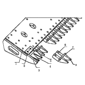
The present invention provides a switchable cutting blade paired with a
harvester knife guard. The
switchable cutting blade comprises a switchable cutting blade assembly
comprising a cutting
bucket steel plate and a plurality of cutting blade bottom frames fixed on the
cutting bucket steel
plate. Each cutting blade bottom frame comprises a triangular part and a
groove frame integrated
with the triangular part. The triangular part protrudes from a front end of
the groove frame along
a direction perpendicular to an upper surface of the groove frame. Each two
adjacent cutting blade
bottom frames are fixed by a crossbar. Each cutting blade bottom frame is
provided with a cutting
blade component comprising a blade part and a mounting part arranged at a rear
end of the blade
part. Each mounting part comprises a groove fixed on the corresponding groove
frame.
Il est décrit un tranchant interchangeable combiné à un doigt de lame de moissonneuse. Le tranchant interchangeable comprend un ensemble de tranchant composé d'une plaque d'acier pour un godet de coupe ainsi que plusieurs bâtis inférieurs de tranchants fixés à la plaque d'acier du godet de coupe. Chaque bâti inférieur de tranchant comprend une pièce triangulaire et un bâti de rainure intégré à cette dernière. La pièce triangulaire saillit d'une partie avant du bâti de rainure le long d'une direction perpendiculaire à une surface supérieure du bâti de rainure. Chaque paire de tranchant et de bâti inférieur adjacents se fixe par une barre transversale. Chaque bâti inférieur de tranchant comprend un composant de tranchant ayant une partie de lame et une partie de montage disposée à l'arrière de la partie de lame. Chaque partie de montage comprend une rainure fixée au bâti de rainure correspondant.
Note: Claims are shown in the official language in which they were submitted.
Note: Descriptions are shown in the official language in which they were submitted.
For a clearer understanding of the status of the application/patent presented on this page, the site Disclaimer , as well as the definitions for Patent , Administrative Status , Maintenance Fee and Payment History should be consulted.
| Title | Date |
|---|---|
| Forecasted Issue Date | 2023-06-20 |
| (86) PCT Filing Date | 2018-08-21 |
| (87) PCT Publication Date | 2020-02-13 |
| (85) National Entry | 2021-05-13 |
| Examination Requested | 2021-05-13 |
| (45) Issued | 2023-06-20 |
There is no abandonment history.
Last Payment of $100.00 was received on 2023-06-23
Upcoming maintenance fee amounts
| Description | Date | Amount |
|---|---|---|
| Next Payment if small entity fee | 2024-08-21 | $100.00 |
| Next Payment if standard fee | 2024-08-21 | $277.00 |
Note : If the full payment has not been received on or before the date indicated, a further fee may be required which may be one of the following
Patent fees are adjusted on the 1st of January every year. The amounts above are the current amounts if received by December 31 of the current year.
Please refer to the CIPO
Patent Fees
web page to see all current fee amounts.
| Fee Type | Anniversary Year | Due Date | Amount Paid | Paid Date |
|---|---|---|---|---|
| Maintenance Fee - Application - New Act | 2 | 2020-08-21 | $50.00 | 2021-05-13 |
| Reinstatement of rights | 2021-05-13 | $204.00 | 2021-05-13 | |
| Application Fee | 2021-05-13 | $204.00 | 2021-05-13 | |
| Maintenance Fee - Application - New Act | 3 | 2021-08-23 | $50.00 | 2021-05-13 |
| Request for Examination | 2023-08-21 | $408.00 | 2021-05-13 | |
| Maintenance Fee - Application - New Act | 4 | 2022-08-22 | $50.00 | 2022-08-03 |
| Final Fee | $153.00 | 2023-04-17 | ||
| Maintenance Fee - Patent - New Act | 5 | 2023-08-21 | $100.00 | 2023-06-23 |
Note: Records showing the ownership history in alphabetical order.
| Current Owners on Record |
|---|
| YE, KONGMENG |
| Past Owners on Record |
|---|
| None |

