Note: Descriptions are shown in the official language in which they were submitted.
TITLE: SEAL ASSEMBLY WITH ANTI-ROTATION AND
STABILITY FEATURES
SPECIFICATION
CROSS-REFERENCE TO RELATED APPLICATIONS
1:0011 This application claims the benefit of U.S. Provisional Application
Ser. No. 62/917,187
filed on November 26, 2018, by Aaron Paul Richie and Lannie Lamy Dietle;
entitled "Seal
Assembly with Anti-rotation and Stability Features." This application also
claims the benefit
of U.S. Provisional Application Ser. No. 62/913,225 filed on October 10,2019,
by Aaron Paul
Richie and Lannie Laroy Dietle and entitled "Seal Assembly with Anti-rotation
and Stability
Features." This application also claims the benefit of -U.S. Patent
Application Ser. No.
16/692,632 filed on November 22, 2019, by Aaron Paul Richie, Lannie Laroy
Dietle, and
Jeffrey D. Gobeli and entitled "Seal Assembly with Anti-rotation and Stability
Features.".
BACKGROUND OF THE INVENTION
1, Field of the Invention.
100021 The present invention relates generally to rotary seals for
establishing sealing between
relatively rotatable machine components and separating a first fluid from a
second fluid More
specifically, the present invention is a rotary shaft scaling assembly that
supports a sealing
element during assembly onto the shaft, and when exposed to reversing
pressure, and prevents
the sealio,, clement from rotating with the shall.
-1-
Date Recue/Date Received 2022-06-08
CA 03120943 2021-05-25
WO 2020/112558
PCT/US2019/062843
2. Description of the Related Att.
[0003] Assignee Kalsi Engineering, Inc. is the owner of numerous patents on
hydrodynamic
seal designs for various applications providing a seal between relatively
rotatable machine
components and separating a first fluid from a second fluid. Oftentimes, the
seal is between a
rotatable shaft and a housing, typically stationary, with the first fluid
acting on a first side of
the seal and the second fluid acting on a second side of the seal. Preferably,
one of the fluids
is a lubricant.
10004] Typically, a hydrodynamic seal has a hydrodynamic lip with a dynamic
sealing surface
which forms a seal with a sealing surface of the shaft when there is no
relative rotatable
movement between the shaft and the housing. Preferably, when the shaft rotates
relative to the
housing, the hydrodynamic seal remains stationary and a thin film of the
lubricant will pass
through the dynamic sealing interface between the dynamic scaling surface of
the
hydrodynamic lip and the sealing surface of the rotatable shaft to minimize
wear and heat
generation. As the thin film of lubricant passes through the dynamic sealing
interface, it
typically becomes a small trace part of the fluid it leaks into.
[00051 Many factors must be considered in the design of rotary shaft sealing
assemblies and
will significantly impact the performance of the sealing assemblies. Such
factors include, for
example, differences of the thermal expansion of the seal element relative to
the housing;
thermal expansion of the fluids; pressure differences between the first and
second fluids,
support for the hydrodynamic sealing element during assembly onto the shaft;
prevention of
the sealing element from rotating with the shaft; and reversing pressures of
the first and second
fluids acting on the sealing element, to name a few.
[0006) Commonly assigned U.S. Patents 7,798,496 and 8,505,924 ("the '496 and
'924
patents') disclosed the use of anti-rotation projections or tangs for engaging
mating recesses
-2-
CA 03120943 2021-05-25
WO 2020/112558
PCT/US2019/062843
within a housing to prevent seal slippage and rotation within housing.
However, in situations
where the pressure of the second (non-lubricant) fluid is greater than the
pressure of the
lubricant in the lubricant-filled region, the seal in the vicinity of the
projection is not supported,
and could be significantly damaged in the '496 and '924 patents.
1.00071 Additionally, in the '496 and '924 patents, the projection is attached
to the seal body
very near the inner periphery of the seal body, which the present inventors
now believe may
cause distortion of the exclusionary circular edge as the projection reacts
seal torque to the
housing, and may inhibit the ability of the circular edge to follow mama
related lateral shaft
motion.
PQM In the '496 and '924 patents, the seal body end nearest the exclusionary
circular edge
is held against a groove wall by differential pressure, and the resulting
friction between that
seal body end and the groove wall inhibits radial slippage between the seal
body end and the
groove wall, which inhibits the ability of the circular edge to follow runout-
related radial
motion of the shaft.
[0009] In the '496 and '924 patents, the exclusionary circular edge is located
at a relatively
small extrusion gap clearance between the housing and the shaft. This exposes
the circular
edge to fluctuating hydraulic pressure related to changes in the extrusion gap
clearance due to
nmout of the shaft, and this fluctuating hydraulic pressure makes the circular
edge less able to
exclude contaminants from the dynamic sealing interface.
[0010] In the prior art, circumferential contact between the projection and
the seal housing
occurs at the sharp knife-like intersection between the lubricant port and the
lubricant-side wall
of the seal groove, making it more likely that the projection will become
damaged or sheared
away as a result of seal torque.
-3-
CA 03120943 2021-05-25
WO 2020/112558
PCT/US2019/062843
[0011] It is desirable to provide a rotary shaft sealing assembly that
overcomes some or all of
the above-mentioned shortcomings of the prior art.
SUMMARY OF THE INVENTION
(0012] A preferred embodiment of the present invention is a rotary shaft
sealing assembly that
preferably includes a rotatable shaft having a sealing surface of generally
cylindrical form
facing generally radially outward. The rotary shaft sealing assembly also
preferably includes
a seal housing of annular form located radially outward of and encircling the
rotatable shaft.
The seal housing preferably has a groove bore facing generally radially inward
toward and
encircling at least a portion of the sealing surface.
[0013] The rotary shaft sealing assembly preferably has a sealing element that
is located
radially between, and has sealing contact with, the sealing surface and the
groove bore. The
sealing element preferably has a seal body of annular form that has seal body
first and second
ends facing in generally opposite directions away from one other. The sealing
element
preferably has a dynamic sealing surface of annular form situated in axially
intermediate
location to the seal body first end and the seal body second end. The dynamic
sealing surface
preferably faces generally radially inward toward and encircles the sealing
surface. Preferably,
the sealing contact between the sealing element and the sealing surface of the
rotatable shaft is
established by the dynamic sealing surface of the sealing element. The sealing
element
preferably has a static sealing surface of annular form situated in axially
intermediate location
to the seal body first end and the seal body second end that faces generally
radially outward
away from the dynamic sealing surface and encircles at least a portion of the
dynamic sealing
surface. The seal body first end preferably has an inner peripheral edge and
an outer peripheral
edge that is located radially outward from the inner peripheral edge.
-4-
CA 03120943 2021-05-25
WO 2020/112558
PCT/US2019/062843
[00141 The sealing element preferably has at least one tang projecting from
the seal body first
end in a generally axial direction away from the seal body second end. The at
least one tang
preferably has an outcr peripheral surface facing in a generally radially
outward direction away
from the rotatable shaft, and an inner peripheral surface facing in a
generally radially inward
direction toward the rotatable shaft. The at least one tang preferably has a
first circumferential
end facing in a generally circumferential direction and a second
circumferential end facing in
a generally opposite circumferential direction. The sealing element preferably
has a first end
fillet located between and adjacent to the first circumferential end and the
seal body first end
and providing a smooth blended transition between the first circumferential
cnd and the seal
body first end. The sealing element preferably has a second end fillet located
between and
adjacent to the second circumferential end and the seal body first end and
providing a smooth
blended transition between the second circumferential end and the seal body
first end.
Preferably the at least one tang is situated in intermediate radial relation
to the dynamic sealing
surface and the static sealing surface and is situated nearer to the outer
peripheral edge than to
the inner peripheral edge.
[l5' The rotary shaft sealing assembly preferably has at least one restraint,
such as a pin,
having a portion thereof in circumferential alignment with the tang and
blocking rotation of the
sealing element. If desired, the at least one restraint may have a portion
located within an at
least one mounting hole in the seal housing or the shelf member.
[00161 The rotary shaft sealing assembly preferably has a shelf member located
radially
outward of the rotatable shaft. The shelf member preferably has a shelf
located radially
between the rotatable shaft and the at least one restraint and located
radially between the
rotatable shaft and the at least one tang. Preferably, the shelf has a shelf
outer surface facing
generally radially outward toward the inner peripheral surface of the at least
one tang and facing
-5-
CA 03120943 2021-05-25
WO 2020/112558
PCT/US2019/062843
generally toward the at least one restraint and blocking disengagement of the
A least one
restraint from the at least one mounting hole, and preventing the restraint
from contacting the
rotatable shaft.
[0017] The at least one restraint is typically a plurality of pins arranged in
a circular pattern
and the at least one tang is typically a plurality of tangs arranged in a
circular pattern. and a
portion of each pin is situated circumferentially between one tang and another
tang.
[001.8] Preferably, the shelf has an inner groove wall facing in a generally
axial direction
toward the seal body first end and the shelf member has an outer groove wall
facing in a
generally axial direction toward the seal body first end and toward the at
least one tang and
toward the at least one restraint Preferably, the seal body first end and the
inner groove wall
face in generally opposite directions and toward one another, the inner groove
wall and the
outer groove wall face in the same general direction, and the outer groove
wall is more distant
than the inner groove wall from the seal body first end.
[0019] Preferably, a corner break is located between and adjacent to the shelf
outer surface and
the inner groove wall. Preferably, the inner peripheral surface of the at
least one tang is blended
to the seal body first end by a tang fillet located between and adjacent to
the inner peripheral
surface and the seal body first end and the corner break faces generally
toward the tang fillet.
[0M0] Preferably, the at least one tang has an axial tang end facing in a
generally axial
direction toward the outer groove wall and the outer groove wall faces
generally toward the
axial tang end.
f00211 Preferably, the shelf member has a pilot surface facing radially
outward toward and
encircled by and adjoining the seal housing and locating the seal housing and
the shelf member
-6-
CA 03120943 2021-05-25
WO 2020/112558
PCT/US2019/062843
radially with respect to one another. Preferably, the groove bore faces
toward, encircles, and
adjoins the pilot surface.
00221 Preferably, the shelf member has a shelf member indexing surface facing
in a generally
axial direction toward the seal housing and the seal housing has a housing
indexing surface
facing in a gencrallIk axial direction toward the shelf member, the housing
indexing surface and
the shelf member indexing surface facing in generally opposite directions
toward one another
and abutting one another and locating the seal housing and the shelf member
axially with
respect to one another.
10023) Preferably, the sealing element has an inlet curvature of generally
convex form that is
adjacent to at least a portion of the dynamic sealing surface. If desired, at
any axial cross-
section of the sealing element, the inlet curvature may be situated in
intermediate relation to
the dynamic sealing surface and the seal body second end, and the inlet
curvature being more
distant than the dynamic sealing surface from the seal body first end and from
the shelf. In
such an arrangement, the sealing element may incorporate an angled
transitional geometry
located between and adjacent to the seal body first end and the cbmamic
sealing surface, the
angled transitional geometry being closer than the dynamic sealing surface to
the shelf.
Alternately, if desired, at any axial cross-section of the sealing element,
the inlet curvature may
be situated in intermediate relation to the dynamic sealing surface and the
seal body first end,
and the inlet curvature being closer than the dynamic sealing surface to the
seal body first end
and to the shelf.
[00243 If desired, a static seal can be used to provide sealing between the
seal housing and the
shelf member.
-7-
[0025] Preferably, the seal housing has a housing groove wall facing in a
generally axial
direction toward and abutting and providing support to the seal body second
end, and
facing the seal body first end, the at least one tang, and the at least one
restraint.
[0026] Preferably, the sealing element partitions a first fluid having a
pressure from a
second fluid having a pressure, the pressure of the first fluid being greater
than the
pressure of the second fluid. Preferably the seal body first end, the at least
one tang, the
at least one restraint, and the shelf are exposed t the first fluid.
[0026A] In a broad aspect, the present invention pertains to a rotary shaft
assembly
comprising a rotatable shaft having a sealing surface of generally cylindrical
form facing
generally radially outward, and a seal housing of annular form located
radially outward of
and encircling the rotatable shaft, and having a groove bore facing generally
radially
inward toward and encircling at least a portion of the sealing surface. A
sealing element
is located radially between and having sealing contact with the sealing
surface and the
groove bore, the sealing element having a seal body first end and a seal body
second end
facing in generally opposite directions away from one other. The seal body
first end has
an inner peripheral edge and an annular outer peripheral edge, at least one
tang being
situated in intermediate radial relation to the inner peripheral edge and the
annular outer
peripheral edge projecting from the seal body first end in a generally axial
direction. The
at least one tang has a first circumferential end facing in a generally
circumferential
direction, an outer peripheral surface facing in a generally radially outward
direction
away from the rotatable shaft, and an inner peripheral surface facing in a
generally
radially inward direction toward the rotatable shaft. A shelf member is
located radially
outward of the rotatable shaft and has
- 7a -
Date Recue/Date Received 2022-06-08
a shelf located radially between the rotatable shaft and the at least one
tang. One of the
seal housing and the shelf member provides at least one restraint, at least a
portion of the
at least one restraint being in circumferential alignment with at least a
portion of the at
least one tang and blocking rotation of the sealing element.
[0026B] In a further aspect, the present invention provides a rotary shaft
sealing
assembly comprising a rotatable shaft having a sealing surface of generally
cylindrical
form facing generally radially outward. A seal housing of annular form is
located
radially outward of and encircling the rotatable shaft, and has a groove bore
facing
generally radially inward toward and encircling at least a portion of the
sealing surface.
A sealing element is located radially between and has sealing contact with the
sealing
surface and the groove bore, the sealing element having a seal body first end
and a seal
body second end facing in generally opposite directions away from one other,
at least one
tang projecting from the seal body first end and in a generally axial
direction away from
the seal body second end. The at least one tang has a first circumferential
end facing in a
generally circumferential direction, an outer peripheral surface facing in a
generally
radial outward direction away from the rotatable shaft, and an inner
peripheral surface
facing in a generally radial inward direction toward the rotatable shaft. A
shelf member
is located radially outward of the rotatable shaft and has a shelf located
radially between
the rotatable shaft and the at least one tang. The shelf has a shelf outer
surface facing
generally radially outward toward the inner peripheral surface of the at least
one tang, and
at least one mounting hole is formed in the seal housing or the shelf member,
the at least
one restraint having a portion thereof located within the at least one
mounting hole and
- 7b -
Date Recue/Date Received 2022-06-08
having a portion thereof located in circumferential alignment with a portion
of the at least
one tang, and blocking rotation of the sealing element. The shelf is located
radially
between the rotatable shaft and the at least one restraint, the shelf outer
surface facing
generally toward at least a portion of the at least one restraint and blocking
the at least
one restraint from contacting the rotatable shaft.
[0026C] In a yet further aspect, the present provides a rotary shaft assembly
comprising
a rotatable shaft having a sealing surface of generally cylindrical form
facing generally
radially outward, and a seal housing of annular form located radially outward
of and
encircling the rotatable shaft and having a groove bore facing generally
radially inward
toward and encircling at least a portion of the sealing surface, the seal
housing having a
housing groove wall facing in a generally axial direction. A shelf member is
located
radially outward of the rotatable shaft and has a shelf with a shelf outer
surface faring
generally radially outward. The shelf member has an outer groove wall and an
inner
groove wall, the outer and inner groove walls facing axially toward the
housing groove
wall and axially offset from one another, with the inner groove wall being
nearer to the
housing groove wall. A sealing element is located radially between and having
sealing
contact with the sealing surface and the groove bore, the sealing element
having a seal
body first end and a seal body second end facing axially in generally opposite
directions
away from one another, at least one tang projecting from the seal body first
end in a
generally axial direction toward the outer groove wall and having an axial
tang end
generally facing the outer groove wall, and at least one tang having a first
circumferential
end facing in a generally circumferential direction. At least one restraint
extends from
the seal housing or the shelf member and has a portion thereof located in
circumferential
alignment with a portion of the at least one tang, blocking rotation of the
sealing element.
- 7c -
Date Recue/Date Received 2022-06-08
The sealing element partitions a first fluid having a pressure from a second
fluid having a
pressure, the seal body first end, the at least one tang, the at least one
restraint and the
shelf being exposed to the first fluid, and the seal body second end being
exposed to the
second fluid. When the second fluid pressure is greater than the first fluid
pressure, the
inner groove wall supports the seal body first end and the outer groove wall
supports the
axial tank end. When the first fluid pressure is greater than the second fluid
pressure, the
housing groove wall supports the seal body second end. The seal body first end
is not
supported by the inner groove wall and the axial tang end is not supported by
the outer
groove wall.
- 7d -
Date Recue/Date Received 2022-06-08
BRIEF DESCRIPTION OF THE SEVERAL VIEWS OF THE DRAWINGS
[0027] The invention is better understood by reading the detailed description
of
embodiments which follows and by examining the accompanying drawings, in
which:
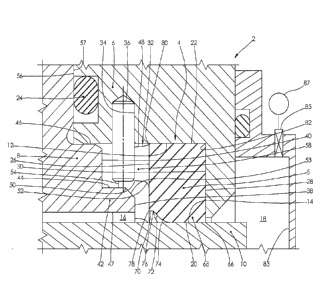
[0028] FIG. 1 is a fragmentary cross-sectional view of a rotary shaft sealing
assembly
according to a preferred embodiment of the present invention;
[0029] FIG. 2 is a perspective view of a sealing element that is illustrated
in FIG. 1;
[0030] FIG. 3 is a cross-sectional view of the sealing element shown in FIG.
2;
[0031] FIG. 4 is a perspective view of a seal housing of the rotary shaft
sealing assembly
of FIG. 1 and a plurality of restraints;
[0032] FIG. 5 is a fragmentary cross-sectional view of a rotary shaft sealing
assembly
according to a second preferred embodiment of the present invention;
[0033] FIG. 6 is a cross-sectional view of a sealing element that is
illustrated in FIG. 5;
[0034] FIG. 7 is a fragmentary cross-sectional view of a rotary shaft sealing
assembly
according to a third preferred embodiment of the present invention;
- 8 -
Date Recue/Date Received 2022-06-08
CA 03120943 2021-05-25
WO 2020/112558
PCT/US2019/062843
[00351 FIGS. 8, 9, 10, II and 12 are fragmentary cross-sectional views of
rotary shaft sealing
assemblies according to other preferred embodiments of the present invention;
and
moi FIG. 12A is a perspective view of a shelf member of the rotary shaft
sealing assembly
of FIG. 12.
DESCRIPTION OF 'THE PREFERRED EMBODIMENTS
[0037] Introduction
[0038] Features throughout this specification that are represented by like
numbers have the
same function.
[0039] In this specification, the definition of the words "adjoin", "adjoins",
and "adjoining"
includes the commonly accepted "adjoin" definition "to be close to or in
contact with one
another" that is provided by the Merriam-Webster online dictionary for the
word "adjoin". In
this specification, the word "intermediate" has the ordinary dictionary
meaning of, "occurring
in the middle of a . . . series" (Merriam-Webster's Learner's Dictionary).
Although these
definitions are provided herein, they are not examples of the inventors being
their own
lexicographers, since the referenced definitions are commonly understood and
accepted
definitions.
[00401 Description of FIGS. I and 5
[00411 FIGURE I is a fragmentary cross-sectional view of a preferred rotary
shaft sealing
assembly that is shown generally at 2. FIGURE 5 is a fragmentary cross-
sectional view of
another preferred rotary shaft sealing assembly that is shown generally at 2.
The following
description applies to both FIG. 1 and FIG. 5.
-9-
CA 031.20943 2021-05-25
WO 2020/112558
PCT/US2019/062843
[00421 A sealing element 4 having a seal body 5 of annular form is located
axially between a
seal housing 6 and a shelf member 8 and is located radially between a portion
of the seal
housing 6 and a portion of a rotatable shaft 10. The rotatable shaft 1() may
have relative rotation
with respect to the sealing element 4, the seal housing 6, and the shelf
member 8. One objective
of the invention is to prevent the sealing element 4 from rotation with the
rotatable shaft 10.
100431 The sealing element 4 may be composed of one or more seal materials
without
departing from the spirit or scope of the invention and may be composed of any
suitable sealing
material or combination of materials, including elastomeric and plastic
materials. The sealing
element 4 may be of monolithic integral, one-piece construction or may also
incorporate
different materials bonded together, chemically cross-linked together, or
inter-fitted together
to form a composite structure.
[00441 The sealing element 4, being a generally circular ring, defines a
theoretical axis. While
the theoretical axis is not illustrated, the term "axis" is well-understood in
the art, and in the
field of drafting is sometimes illustrated using a centerline. For orientation
purposes, it should
be understood that in all of the cross-sectional views herein, the cutting
plane of the cross-
section is aligned with and passes through the theoretical axis of the sealing
element 4; i.e., the
theoretical centerline lies on the cutting plane. In other words, all of the
cross-sectional views
herein are longitudinal section views. The circumferential direction of
relative rotation is
normal (perpendicular) to the plane of the cross-section, and the theoretical
axis of sealing
element 4 generally coincides with the axis of relative rotation.
[06451 Preferably, the sealing element 4 is located between, radially
compressed between, and
establishes sealing contact with a groove bore 12 of the seal housing 6 and a
sealing surface 14
of the rotatable shaft 10 and partitions a first fluid 16 from a second fluid
18. More specifically,
a dynamic sealing surface 20 of the sealing element 4 preferably establishes
the sealing contact
-10-
CA 03120943 2021-05-25
WO 2020/112558
PCT/US2019/062843
with the sealing surface 14 of the rotatable shaft 10, and a static sealing
surface 22 of the sealing
element 4 preferably establishes sealing contact with the groove bore 12 of
the seal housing 6.
100461 For purposes of this specification, the term "fluid" has its broadest
meaning,
encompassing both liquids and gases. If desired, a static seal 24 may be used
to provide sealing
between the seal housing 6 and the shelf member 8. In some situations, the
static seal 24 is not
necessary. For example, in some situations the seal housing 6 may have a
sealed relationship
with some other component that the seal housing 6 and shelf member 8 are
located within, and
in some circumstances that sealed relationship would eliminate the need for
the static seal 24.
This is not the only situation where the static seal 24 is not required.
[0047) Preferably, a seal body first end 26 of the sealing element 4 faces in
a generally axial
direction toward the shelf member 8, and a seal body second end 28 of the
sealing element 4
faces in a generally axial direction away from the shelf member 8 and faces in
a generally axial
direction toward and may adjoin a housing groove wall 30 of the seal housing
6.
[00481 Preferably, at least one (i.e., one or more) tang 32 projects from the
seal body first end
26 in a generally axial direction, projecting generally away front the seal
body second end 28
and housing groove wall 30 and generally toward the shelf member 8. In most
cases more than
one tang 32, arranged in a circular pattern, will be used. With very small
diameter seals, it is
possible that only one tang 32 would be used due to space constraints.
100491 Preferably, the assembly has at least one restraint 36, such as the
generally cylindrical
pin that is shown, which, through interaction with the tang 32, prevents
(i.e., blocks) the sealing
clement 4 from rotating with the rotatable shaft 10. In most cases more than
one restraint 36,
arranged in a circular pattern, will be used. With very small diameter seals,
it is possible that
only one restraint 36 would be used due to space constraints.
-11-.
CA 03120943 2021-05-25
WO 2020/112558
PCT/US2019/062843
[0050] Preferably, at least one mounting hole 34 is formed in the seal housing
6. In most cases
more than one mounting hole 34, arranged in a circular pattern, will be used.
With very small
diameter seals, it is possible that only one mounting hole 34 would be used
due to space
constraints. Preferably, each mounting hole 34 is situated in a generally
radial orientation, as
illustrated. Preferably, each mounting hole 34 has an end facing radially
inward toward the
rotatable shaft 10. Although the mounting hole 34 is shown as a blind hole
(i.e., one that does
not pass completely through the seal housing 6), arrangements are possible
where the mounting
hole 34 is a through hole that does pass completely through to the outer
peripheral surface (not
shown here) of the seal housing 6.
100511 Preferably, each restraint 36 is located by and secured partially
within a mating
mounting hole 34. In other words, preferably, there is at least one restraint
having a portion
thereof located within the at least one mounting hole 34. Preferably, each
restraint 36 and
mounting hole 34 is generally radially oriented. Each restraint 36 is
preferably retained within
its mating mounting hole 34 by friction produced by an interference fit
between the restraint
36 and the mounting hole 34. The seal housing 6, shelf member 8, rotatable
shaft 10, and
restraint 36 are preferably made at least in part from metal, and the sealing
surface 14 preferably
has a coating or treatment to enhance hardness. The hardness enhancement is
typically a
tungsten carbide coating.
[00523 Although any suitable type of pin can be used as the restraint 36, the
preferred pin type
is known as a grooved pin. Groom' pins have a longitudinal groove that creates
displaced
metal that produces interference and friction with the mounting hole 34 when
installed.
Grooved pins are preferred over dowel pins because grooved pins are compatible
with a larger
diameter tolerance on the mounting hole 34. Dowel pins, coiled spring pins,
and roll pins (also
-12-
CA 031.20943 2021-05-25
WO 2020/112558
PCT/US2019/062843
known as slotted spring pins) are other examples of pins that are suitable for
use as the restraint
36.
100531 The sectional views herein are intended to be interpreted by the
standard conventions
of multi and sectional view orthographic drawing projection practiced in the
United States and
described in ANSI Y14.3-1975, an industry standardization document promulgated
by ASM.E.
ANSI Y14.3-1975 has been interpreted to mean that the restraint 36 should not
be sectioned
because a groove pin has no internal detail to be conveyed.
10054] Preferably, each restraint 36 has a portion thereof that is
circumferentially aligned with
at least one tang 32 and through interaction with the tang 32 prevents (i.e.,
blocks) the sealing
element 4 from rotating with the rotatable shaft 10. Preferably, in the
typical assembly with
more than one restraint 36 and more than one tang 32, each restraint 36 is
located
circumferentially between a first and a second tang 32, and each tang 32 is
located
circtunferentially between a first and a second restraint 36, and there arc as
many of the restraint
36 as there are of the tang 32. In other words, preferably, in the typical
case where there is
more than one tang 32 and more than one restraint 36, a portion of each tang
32 is situated in
circumferentially intermediate location to a pair of restraints 36 and a
portion of each restraint
36 is situated in circumferentially intermediate location to a pair of tangs
32.
1:00551 Preferably, the housing groove wall 30 faces in a generally axial
direction toward and
adjoining (and typically abutting) the seal body second end 28, and faces
toward the seal body
first end 26, the at least one tang 32, and the at least one restraint 36.
[94561 Preferably, the shelf member 8 defines a shelf 42 that is an annular
feature projecting
in an axial direction toward the sealing element 4 and the housing groove wall
30. Preferably,
the shelf member 8 has an inner groove wall 38 and an outer groove wall 40
that are axially
offset from one another. Preferably, the inner groove wall 38 is an end
surface of the shelf 42
-13-
CA 03120943 2021-05-25
WO 2020/112558
PCT/US2019/062843
and faces in a generally axial direction toward the seal body first end 26 and
housing groove
wall 30. Preferably, the outer groove wall 40 faces in a generally axial
direction toward each
restraint 36 and each tang 32 and faces in a generally axial direction toward
the seal body first
end 26 and the housing groove wall 30. Preferably, a shelf outer surface 44 of
the shelf 42
faces radially outward toward each restraint 36, preventing each restraint 36
from disengaging
from its mating mounting hole 34. Preferably, the housing groove wall 30,
inner groove wall
38, and outer groove wall 40 are substantially planar (i.e., substantially
flat) surfaces.
town The sealing element 4 is illustrated in the axial position it attains
when the pressure of
the first fluid 16 is greater than the pressure of the second fluid 18.
Preferably, at least a portion
of the seal body second end 28 is supported by the housing groove wall 30 when
the pressure
of the first fluid 16 is greater than the pressure of the second fluid 18. The
seal body second
end 28 is also supported by the housing groove wall 30 if the sealing element
4 is being installed
onto the rotatable shaft 10 from right to left.
[0050] Preferably, the seal body first end 26 is supported by the inner groove
wall 38 if the
pressure of the second fluid 18 is greater than the pressure of the first
fluid 16. Preferably, the
seal body first end 26 is also supported by the inner groove wall 38 if the
sealing element 4 is
being installed onto the rotatable shaft 10 from left to right, preventing
significant installation-
related cross-sectional twisting of the sealing element 4. This stabilizing
benefit helps to ensure
proper installation and helps to minimize pressure induced distortion of the
sealing element 4.
[0059.1 Preferably, each of the at least one tang 32 are supported by the
outer groove wall 40 if
the pressure of the second fluid 18 is greater than the pressure of the first
fluid 16. The tangs
32 may also be supported by the outer groove wall 40 if the sealing element 4
is being installed
onto the rotatable shaft 10 from left to right. This stabilizing benefit helps
to ensure proper
installation and helps to minimize pressure induced distortion of the sealing
element 4.
-14-
CA 031.20943 2021-05-25
WO 2020/112558
PCT/US2019/062843
[00601 Preferably, the shelf member 8 has a pilot surface 46 that faces
radially outward toward
and adjoining the groove bore 12 and locates the shelf member 8 and the groove
bore 12
laterally with respect to one another, ensuring good alignment between the
shelf member 8 and
the seal housing 6. Preferably, the shelf member 8 and the seal housing 6 are
generally
concentric with each other as a result of this piloted relationship.
Preferably, at least part of
the pilot surface 46 is located radially inward from and within (i.e., inside
of) a portion of the
groove bore 12. Preferably, the shelf member 8 has a shelf bore 47 that faces
generally radially
inward toward and encircles a portion of the rotatable shaft 10.
[00611 Preferably, each tang 32 has an outer peripheral surface 48 that faces
generally radially
outward toward the groove bore 12 and away from the sealing surface 14 and the
rotatable shaft
10. Preferably each tang 32 has an inner peripheral surface 50 that faces
generally radially
inward away from the groove bore 12 and generally toward the shelf 42, the
shelf outer surface
44, the rotatable shaft 10 and the sealing surface 14. Preferably, the outer
peripheral surface
48 and inner peripheral surface 50 face in generally radially opposite
directions, away from
one another. Preferably, the inner peripheral surface 50 is blended to the
seal body first end 26
with a tang fillet 52 that is generally concave, as can be seen in the
longitudinal cross-sections
of FIGS. 1 and 5. One purpose of the tang fillet 52 is to increase the contact
area between the
tang 32 and the annular portion of the sealing element 4 that the tang 32
projects from, to reduce
seal torque-induced stress at the root of the tang 32 (i.e., to reduce shear
stress at the interface
between the tang 32 and the seal body 5). This helps to prevent the tang 32
from tearing loose
from the remainder of the sealing element 4. Preferably, the tang fillet 52 is
located between
and adjacent to the inner peripheral surface 50 and the seal body full end 26
and provides a
smooth blended transition between the inner peripheral surface 50 and the seal
body first end
26. In other words, preferably the tang fillet 52 blends between the inner
peripheral surface 50
and the seal body first end 26.
-15-
CA 031.20943 2021-05-25
WO 2020/112558
PCT/US2019/062843
[00621 Preferably, the shelf 42 incorporates a corner break 53 between the
shelf outer surface
44 and the inner groove wall 38 to provide clearance for the tang fillet 52 in
circumstances
where the seal body first end 26 is forced into contact with the inner groove
wall 38. Preferably,
the corner break 53 geometry is selected from a group consisting of chamfers
and rounds, the
term "round" having the common industrial meaning of a rounded external
corner. Preferably,
the corner break 53 is located between and adjacent to the shelf outer surface
44 and the inner
groove wall 38. Preferably, the corner break 53 faces generally toward the
tang fillet 52.
00031 Preferably each of the tangs 32 has a first circumferential end 58 that
faces in a generally
circumferential direction toward a restraint 36. Preferably, each tang 32 has
an axial tang end
54 that faces in generally the same axial direction as the seal body first end
26. The axial tang
end 54 faces generally toward the outer groove wall 40 and may abut the outer
groove wall 40
in circumstances where the pressure of the second fluid 18 is greater than the
pressure of the
first fluid 16. Preferably, the axial tang end 54 is generally planar (i.e.,
flat).
1,0004) Preferably, each tang 32 has an axial length defined by the distance
from the axial tang
end 54 to the seal body first end 26 and the shelf 42 has an axial length
defined by the distance
from the inner groove wall 38 to the outer groove wall 40. Preferably, the
tang axial length
and the shelf axial length are the same or substantially the same so that the
inner groove wall
38 and the outer groove wall 40 may provide support to the seal body first end
26 and the axial
tang end 54, respectively, concurrently under certain operating and
installation conditions.
10($65) Preferably, the seal housing 6 has a housing indexing surface 56 of
generally planar
form that faces in a generally axial direction toward the shelf member S.
Preferably, the shelf
member 8 has a shelf member indexing surface 57 of generally planar form that
faces in a
generally axial direction toward and abuts the housing indexing surface 56 of
the seal housing
6. Preferably, the contact between the housing indexing surface 56 and the
shelf member
-16-
CA 03120943 2021-05-25
WO 2020/112558
PCT/US2019/062843
indexing surface 57 locates the seal housing 6 and the shelf member 8 axially
with respect to
one another. Preferably, the housing indexing surface 56 and the shelf member
indexing
surface 57 face in generally opposite directions toward each other.
[00661 Preferably, the dynamic sealing surface 20 is annular. Preferably, the
dynamic sealing
surface 20 terminates at an exclusionary corner 66 that is generally circular
and is an external
corner. Preferably, the dynamic sealing surface 20 varies in axial width
around the
circumference of the sealing element 4.
19007] Preferably, the dynamic sealing surface 20 is an inner peripheral
surface of a dynamic
sealing lip 68 that projects radially inward from an inner body surface 70 of
the sealing element
4. Preferably, the dynamic sealing lip 68 has an angled flank 72 that is
situated in axially
intermediate relation to the inner body surface 70 and the dynamic sealing
surface 20 at any
axial cross-section of the sealing element 4.
[00681 Preferably, the dynamic sealing lip 68 has an inlet curvature 74 of
generally convex
form that is situated in axially intermediate location to the angled flank 72
and the dynamic
sealing surface 20 at any axial cross-section of the sealing clement 4.
Preferably, the inlet
curvature 74 is located adjacent to and abuts the angled flank 72. Preferably,
as a result of the
varying axial width of the dynamic sealing surface 20, the dynamic sealing
surface 20 has a
wavy edge and the inlet curvature 74 is located adjacent to and abuts at least
a portion of the
wavy edge of the dynamic sealing surface 20. In other words, the inlet
curvature 74 is
preferably adjacent to at least a portion of the dynamic sealing surface 20,
and the dynamic
sealing surface 20 is preferably adjacent to at least a portion of the inlet
curvature 74.
Preferably, the dynamic sealing surface 20 encircles and adjoins the sealing
surface 14 of the
rotatable shaft 10, contacting the rotatable shaft 10 in the absence of
relative rotation, and
-17-
CA 031.20943 2021-05-25
WO 2020/112558
PCT/US2019/062843
generally separated from the rotatable shaft 10 by a very thin film during
periods of relative
rotation.
[00691 Preferably, the axial distance between the inlet curvature 74 and the
exclusionary corner
66 varies around the circumference of the sealing element 4. Preferably, the
axial distance
between the inlet curvature 74 and the seal body second end 28 varies around
the circumference
of the sealing element 4. Preferably, the axial distance between the inlet
curvature 74 and the
housing groove wall 30 varies around the circumference of the sealing element
4. Preferably,
the axial distance between the inlet curvature 74 and the seal body first end
26 varies around
the circumference of the sealing element 4. Preferably, the inlet curvature 74
provides a smooth
blend between the dynamic sealing surface 20 and the angled flank 72.
Preferably, the inlet
curvature 74 follows a wavy path around the circumference of the sealing
element 4 as it
follows the wavy edge of the dynamic sealing surface 20.
190701 Preferably, the angled flank 72 terminates at a wavy intersection 76
with the inner body
surface 70. Preferably, the angled flank 72 is angulated with respect to the
dynamic sealing
surface 20 and with respect to the inner body surface 70. Preferably, the
axial distance between
the angled flank 72 and the exclusionary corner 66 varies around the
circumference of the
sealing element 4. Preferably, the axial distance between the angled flank 72
and the seal body
second end 28 varies around the circumference of the sealing element 4.
Preferably, the axial
distance between the angled flank 72 and the housing groove wall 30 varies
around the
circumference of the sealing element 4. Preferably, the axial distance between
the angled flank
72 and the seal body first end 26 varies around the circumference of the
sealing element 4.
[0071.1 The dynamic sealing surface 20, angled flank 72, and inlet curvature
74 of the dynamic
sealing lip 68 of the sealing element 4 preferably form hydrodynamic waves.
The dynamic
sealing lip 68 may incorporate the hydrodynamic waves taught by any the
following commonly
-18-.
CA 031.20943 2021-05-25
WO 2020/112558
PCT/US2019/062843
assigned U.S. patents, which are incorporated herein for all purposes:
4,610,319, 5,230,520,
5,738,358, 5,873,576, 6,036,192, 6,109,618, 6,120,036, 6,315,302, 6,334,619,
6,382,634,
6,685,194, 6,767,016, 7,052,020. 7,562,878, 8,056,904, 8,550,467, 9,086,151,
9,103,445,
9,121,503, 9,121,504, and 10,302,200.
10072] Preferably, the seal body first end 26 has an inner peripheral edge 78
of annular form
and an outer peripheral edge 80 of annular form. Preferably, the outer
peripheral edge 80 is
annular and is located radially outward from and encircles the inner
peripheral edge 78
Preferably, the inner peripheral edge 78 is annular and is located radially
inward from and
encircled by the outer peripheral edge 80.
190731 Preferably, the at least one tang 32 is situated in intermediate radial
relation to and
between the inner peripheral edge 78 and the outer peripheral edge 80.
Preferably, the at least
one tang 32 is located closer (i.e., nearer) to the outer peripheral edge 80
than it is to the inner
peripheral edge 78. Another way of saying this is that preferably, the outer
peripheral edge 80
is nearer than the inner peripheral edge 78 to the at least one tang 32.
V00741 This outward radial placement of the at least one tang 32 accomplishes
several things.
First, this outward radial placement of the tang 32 allows the exclusionary
corner 66 to more
effectively exclude abrasive particulate matter from the sealing interface
between the dynamic
sealing surface 20 and the sealing surface 14. We think this is because the
outward radial
placement of the tang 32 isolates the exclusionary corner 66 from distortion
of the seal body 5
caused by the reaction of the tang 32 to the torque of the sealing element 4
as the tang 32
prevents rotation of the sealing element 4 with the rotatable shaft 10, which
helps to maintain
the circularity of the exclusionary corner 66 during relative rotation. We
also think the outward
radial placement of the tang 32 allows the exclusionary corner 66 to better
follow runout related
lateral motion of the sealing surface 14, which improves the exclusionary
function of the
-19-
CA 03120943 2021-05-25
WO 2020/112558
PCT/US2019/062843
exclusionary corner 66. Whatever the reasons, in our laboratory experiments we
found that
when a tang is located near the inner peripheral edge of the seal body first
end, the exclusionary
performance of the exclusionary corner 66 is significantly diminished,
resulting in significantly
more third body abrasion of the seal.
190751 Second, the outward radial placement of the tang 32 allows space for
the shelf 42 to be
located radially inward from the restraint 36, to prevent inadvertent loss of
the restraint 36, and
to position the shelf 42 and a mating portion of the seal body first end 26 at
the proper location
to allow the shelf 42 to provide axial support to the seal body 5 (via contact
with the seal body
first end 26) during installation of the sealing element 4 onto the sealing
surface 14 of the
rotatable shaft 10, and during periods of operation where the pressure of the
second fluid 18 is
greater than the first fluid 16.
(0076] Third, the outward radial placement of the tang 32 places it at a
location on the seal
body 5 that allows the tang 32 to have more circumferential length, which
provides additional
strength to the tang 32, making the tang 32 more capable of resisting the
torque of the sealing
element 4, and less likely to tear lose from the seal body 5.
1.00771 Fourth, the outward radial placement of the tang 32 provides the tang
32 with an
increased mechanical advantage to better resist the torque of the sealing
element 4.
[907.8] Preferably, the sealing element 4 is located radially inward from and
encircled by at
least a portion of the seal housing 6. Preferably, the sealing element 4 is
located radially
outward from and encircles at least a portion of the rotatable shaft 10.
Preferably, at least a
portion of the sealing element 4 is located axially between the at least one
restraint 36 and the
housing groove wall 30. Preferably, a/ least a portion of the sealing element
4 is located axially
between the outer groove wall 40 and the housing groove wall 30. Preferably,
at least a portion
of the sealing element 4 is located axially between the inner groove wall 38
and the housing
-20-
CA 03120943 2021-05-25
WO 2020/112558
PCT/US2019/062843
groove wall 30. Preferably, at least a portion of the sealing element 4 is
located axially between
the shelf 42 and the housing groove wall 30. Preferably, at least a portion of
the sealing element
4 is located axially between the first fluid 16 and the second fluid 18 and
partitions the first
fluid 16 from the second fluid 18.
100791 Preferably, at least a portion of the seal housing 6 is located
radially outward from and
encircles at least a portion of the sealing element 4. Preferably, at least a
portion of the seal
housing 6 is located radially outward from and encircles at least a portion of
the rotatable shaft
10. The seal housing 6 preferably abuts the shelf member 8 and preferably
encircles at least a
portion of the pilot surface 46. Preferably, at least a portion of the seal
housing 6 is located
radially outward from and encircles at least a portion of the shelf 42.
Preferably, at least a
portion of the seal housing 6 is located radially outward from and encircles
at least a portion of
the inner groove wall 38 and the outer groove wall 40. Preferably, at least a
portion of the seal
housing 6 is located radially outward from and encircles at least a portion of
the seal body first
end 26 and the seal body second end 28.
MOM Preferably, the shelf member 8 is located radially outward from and
encircles at least a
portion of the rotatable shaft 10. Preferably, a portion of the shelf member 8
is located radially
inward from and encircled by the groove bore 12. Preferably, the shelf member
8 is located
radially relative to the seal housing 6 by the groove bore 12 of the seal
housing 6. Preferably,
a portion of the shelf member 8 is located radially inward from the at least
one restraint 36.
Preferably, a portion of the shelf member 8 is located radially inward from
the at least one tang
32. Preferably, a portion of the shelf member 8 is located radially between
the at least one
restraint 36 and the rotatable shaft 10. Preferably, a portion of the shelf
member 8 is located
radially between the at least one tang 32 and the rotatable shaft 10.
-21-
CA 03120943 2021-05-25
WO 2020/112558
PCT/US2019/062843
[00811 Preferably, at least a portion of the rotatable shaft 10 is located
radially inward from
and encircled by the sealing element 4. Preferably, at least a portion of the
rotatable shaft 10
is located radially inward from and encircled by thc seal housing 6.
Preferably, at least a
portion of the rotatable shaft 10 is located radially inward from and
encircled by the shelf
member 8. Preferably, at least a portion of the rotatable shaft 10 is located
radially inward
from and encircled by the shelf 42. Preferably, at least a portion of the
rotatable shaft 10 is
located radially inward from and encircled by the outer groove wall 40.
Preferably, at least a
portion of the rotatable shaft 10 is located radially inward from and
encircled by the inner
groove wall 38. Preferably, at least a portion of the rotatable shaft 10 is
located radially inward
from the at least one restraint 36. Preferably, at least a portion of the
rotatable shaft 10 is
located radially inward from the at least one tang 32.
100821 Preferably, the groove bore 12 is cylindrical. Preferably, the groove
bore 12 faces
radially inward. Preferably, a portion of the groove bore 12 faces radially
inward toward and
encircles at least a portion of the sealing element 4. Preferably, a portion
of the groove bore
12 faces radially inward toward and encircles at least a portion of each of
the at least one tang
32. Preferably, a portion of the groove bore 12 faces radially inward toward
and encircles at
least a portion of the shelf 42 of the shelf member 8. Preferably, a portion
of the groove bore
12 faces radially inward toward and encircles at least a portion of the shelf
outer surface 44 of
the shelf 42. Preferably, a portion of the groove bore 12 faces radially
inward toward and
encircles at least a portion of the pilot surface 46 of the shelf member 8.
Preferably, a portion
of the groove bore 12 faces radially inward toward and encircles at least a
portion of the inner
groove wall 38. Preferably, a portion of the groove bore 12 faces radially
inward toward and
encircles at least a portion of the outer groove wall 40. Preferably, a
portion of the groove bore
12 faces radially inward toward, abuts, and has a sealed relationship with the
static sealing
-22-
CA 03120943 2021-05-25
WO 2020/112558
PCT/US2019/062843
surface 22 of the sealing element 4. Preferably, the groove bore 12 faces
radially inward toward
and encircles at least a portion of the sealing surface 14 of the rotatable
shaft 10.
[04M31 Preferably, the sealing surface 14 is generally cylindrical, and faces
generally radially
outward. Preferably, at least a portion of the sealing surface 14 faces
radially outward toward
and is in sealing engagement with the dynamic sealing surface 20 of the
sealing element 4.
Preferably, at least a portion of the sealing surface 14 faces radially
outward toward and is
encircled by at least a portion of the groove bore 12. Preferably, at least a
portion of the sealing
surface 14 faces radially outward toward and is encircled by at least a
portion of the seal
housing 6. Preferably, at least a portion of the sealing surface 14 faces
radially outward toward
and is encircled by at least a portion of the shelf 42 of the shelf member 8.
Preferably, at least
a portion of the sealing surface 14 faces radially outward toward the at least
one =taint 36.
Preferably, at least a portion of the sealing surface 14 faces radially
outward toward the at least
one tang 32. Preferably, at least a portion of the sealing surface 14 is
located radially inward
from the at least one restraint 36. Preferably, at least a portion of the
sealing surface 14 is
located radially inward from the at least one tang 32.
[00841 Preferably. at least part of the first fluid 16 is located radially
outward from and is in
contact with a portion of the sealing surface 14 of the rotatable shaft 10.
Preferably, the first
fluid 16 contacts the scaling element 4, the seal housing 6, the shelf member
8, the rotatable
shaft 10, the groove bore 12, the sealing surface 14, the static seal 24, the
seal body first end
26, evely tang 32, every restraint 36, the inner groove wall 38, the outer
groove wall 40, the
shelf 42, the shelf outer surface 44, the pilot surface 46, and the shelf bore
47.
[00851 Preferably, at least part of the second fluid 18 is located radially
outward from and is in
contact with a portion of the sealing surface 14 of the rotatable shaft 10.
Preferably, the second
-23-
CA 03120943 2021-05-25
WO 2020/112558
PCT/US2019/062843
fluid 18 contacts a portion of the sealing element 4, the seal housing 6, the
rotatable shaft 10.
and the sealing surface 14.
r0061 Preferably, the dynamic sealing surface 20 of the sealing element 4
faces generally
radially inward toward and adjoins the sealing surface 14 of the rotatable
shaft 10. Preferably,
the dynamic sealing surface 20 has an axial width that varies around the
circumference of the
sealing element 4, for the promotion of hydrodynamic film lubrication of the
dynamic sealing
interface between the dynamic sealing surface 20 and the sealing surface 14
during periods
when the rotatable shaft 10 has relative rotation with respect to the sealing
element 4.
Preferably, the dynamic sealing surface 20 faces generally away from and in
generally the same
direction as the groove bore 12. Preferably, the dynamic sealing surface 20
and the static
sealing surface 22 face in generally opposite radial directions, away from one
another.
[00871 Preferably, the dynamic scaling surface 20 is sitnatod in axially
intermediate location
to the seal body first end 26 and the seal body second end 28. Preferably, the
dynamic sealing
surface 20 is situated in axially intermediate location to the at least one
tang 32 and the seal
body second end 28. Preferably, the dynamic sealing surface 20 is situated in
axially
intermediate location to the at least one restraint 36 and the seal body
second end 28.
KX/80j Preferably, the static sealing surface 22 of the sealing element 4
faces in a generally
radially outward direction, away from the sealing surface 14 of the rotatable
shaft 10 and
toward and abutting the groove bore 12 of the seal housing 6. Preferably, the
static sealing
surface 22 is situated in axially intermediate location to the seal body first
end 26 and the seal
body second end 28. Preferably, the static sealing surface 22 is situated in
axially intermediate
location to the at least one tang 32 and the seal body second end 28.
Preferably, the static
sealing surface 22 is situated in axially intermediate location to the at
least one restraint 36 and
-24-
CA 03120943 2021-05-25
WO 2020/112558
PCT/US2019/062843
the seal body second end 28. Preferably, the static sealing surface 22 is
located radially outward
from and encircles at least a portion of the dynamic sealing surface 20.
r00891 Preferably, the static seal 24 is a face-sealing element such as the 0-
ring that is
illustrated, and establishes sealing with and between the seal housing 6 and
the shelf member
8. Preferably, the static seal 24 is located radially outward from and
encircles a portion of the
groove bore 12. Preferably, the static seal 24 is located radially outward
from and encircles a
portion of the pilot surface 46. Preferably, the static seal 24 is located
radially outward from
and encircles a portion of the shelf member 8. Preferably, the static seal 24
is located radially
outward from and encircles a portion of the rotatable shaft 10.
to0901 Preferably, the seal body first end 26 faces in a generally axial
direction toward the at
least one restraint 36, inner groove wall 38, outer groove wall 40, shelf 42.
shelf outer surface
44 and shelf bore 47. Preferably, the seal body first end 26 faces in a
generally axial direction
away from the housing groove wall 30 and the seal body second end 28.
Preferably, the seal
body first end 26 and the seal body second end 28 face in generally opposite
directions, away
from each other. Preferably, the seal body first end 26 faces in the same
generally axial
direction that the housing groove wall 30 faces. Preferably, seal body first
end 26 is located
radially inward from and is encircled by the groove bore 12 of the seal
housing 6.
[00911 Preferably, the seal body second end 28 faces in a generally axial
direction toward the
housing groove wall 30 and away from the seal body first end 26, the at least
one tang 32, the
at least one restraint 36, inner groove wall 38, outer groove wall 40, shelf
42, shelf outer surface
44, and shelf bore 47.
10094 Preferably, the seal body second end 28 is situated in axially
intermediate location to
the housing groove wall 30 and the seal body first end 26. Preferably, the
seal body second
end 28 is situated in axially intermediate location to the housing groove wall
30 and the at least
-25-
CA 03120943 2021-05-25
WO 2020/112558
PCT/US2019/062843
one tang 32. Preferably, the seal body second end 28 is situated in axially
intermediate location
to the housing groove wall 30 and the at least one restraint 36. Preferably,
the seal body second
end 28 is situated in axially intermediate location to the housing groove wall
30 and the inner
groove wall 38. Preferably, the seal body second end 28 is situated in axially
intermediate
location to the housing groove wall 30 and the outer groove wall 40.
Preferably, the seal body
second end 28 is situated in axially intermediate location to the housing
groove wall 30 and the
shelf 42. Preferably, the seal body second end 28 is situated in axially
intermediate location to
the housing groove wall 30 and the shelf outer surface 44. Preferably, the
seal body second
end 28 is situated in axially intermediate location to the housing groove wall
30 and the pilot
surface 46. Preferably, the seal body second end 28 is situated in axially
intermediate location
to the housing groove wall 30 and the shelf bore 47. Preferably, the seal body
second end 28
is located radially inward from the groove bore 12. Preferably, the seal body
second end 28 is
located radially inward from and is encircled by a portion of the seal housing
6.
[00931 Preferably, the housing groove wall 30 faces in a generally axial
direction toward the
seal body first end 26, seal body second end 28, the at least one tang 32, the
at least one restraint
36, inner groove wall 38, outer groove wall 40, shelf 42, shelf outer surface
44, pilot surface
46, and shelf bore 47. Preferably, the housing groove wall 30 and the inner
groove wall 38
face in generally opposite directions, toward one another. Preferably, the
housing groove wall
30 and the outer groove wall 40 face in generally opposite directions, toward
one another.
Preferably, the inner groove wall 38 and the outer groove wall 40 face in the
same general axial
direction. Preferably, the outer groove wall 40 is more distant than the inner
groove wall 38
from the seal body first end 26 and from the housing groove wall 30.
[00941 Preferably, each tang 32 is situated in axially intermediate location
to the outer groove
wall 40 and the seal body first end 26. Preferably, each tang 32 is situated
in axially
-26-
CA 03120943 2021-05-25
WO 2020/112558
PCT/US2019/062843
intermediate location to the outer groove wall 40 and the seal body second end
28. Preferably,
each tang 32 is situated in axially intermediate location to the outer groove
wall 40 and the
housing groove wall 30. Preferably, each tang 32 is located directly between
the outer groove
wall 40 and the seal body 5.
100951 Preferably, when there is more than one tang 32, they are
circumferentially spaced from
one another. Preferably, each tang 32 is located radially inward from and
encircled by the
groove bore 12. Preferably, each tang 32 is located radially outward from the
shelf 42.
Preferably, each tang 32 is located radially outward from the shelf outer
surface 44. Preferably,
each tang 32 is located radially outward from the sealing surface 14.
Preferably, each tang 32
is situated in radially intermediate location to at least a portion of the
rotatable shaft 10 and the
groove bore 12. Preferably, each tang 32 is situated in radially intermediate
location to the
sealing surface 14 and the groove bore 12. Preferably, each tang 32 is
situated in radially
intamediate location to the inner groove wall 38 and the groove bore 12.
Preferably, each tang
32 is situated in radially intermediate location to the shelf 42 and the
groove bore 12.
Preferably, each tang 32 is situated in radially intermediate location to the
shelf outer surface
44 and the groove bore 12. Preferably, each tang 32 is situated in radially
intermediate location
to the shelf bore 47 and the groove bore 12. Preferably, each tang 32 is
situated in radially
intermediate location to the corner break 53 and the groove bore 12.
Preferably, each tang 32
is situated in radially intermediate location to the dynamic sealing surface
20 and the static
sealing surface 22.
100961 Preferably, each mounting hole 34 is located radially outward from the
shelf outer
surface 44. Preferably, each mounting hole 34 is located radially outward from
the shelf 42.
Preferably, each mounting hole 34 is located radially outward from the sealing
surface 14.
-27-
CA 03120943 2021-05-25
WO 2020/112558
PCT/US2019/062843
Preferably, when more than one mounting hole 34 is used, they are
circumferentially spaced
from one another.
[00971 Preferably, each restraint 36 is located by and is located partially
within its mating
mounting hole 34. Preferably, each restraint 36 is situated in axially
intermediate location to
the outer groove wall 40 and the seal body first end 26. Preferably, each
restraint 36 is situated
in axially intermediate location to the outer groove wall 40 and the seal body
second end 28.
Preferably, each restraint 36 is situated in axially intermediate location to
the outer groove wall
40 and the housing groove wall 30. Preferably, each restraint 36 is located
radially outward of
the shelf 42. Preferably, each restraint 36 is located radially outward of the
shelf outer surface
44. Preferably, each restraint 36 is located radially outward of the sealing
surface 14.
Preferably, each restraint 36 is located radially outward of the rotatable
shaft 10. Preferably,
each restraint 36 has an axis, and the axis is oriented radially. Preferably,
each restraint 36 has
a portion thereof that is located within its mating mounting hole 34 and
located radially outward
of the groove bore 12. Preferably, when there is more than one restraint 36,
each restraint 36
is circumferentially spaced from the others.
E00981 Preferably, the inner groove wall 38 faces in a generally axial
direction toward the seal
body first end 26, seal body second end 28, and the housing groove wall 30.
Preferably, the
inner groove wall 38 and the seal body second end 28 face in the same general
axial direction.
Preferably, the inner groove wall 38 and the housing groove wall 30 face in
generally opposite
directions and toward each other. Preferably, the inner groove wall 38 and the
seal body first
end 26 face in generally opposite directions and toward each other.
Preferably, the inner groove
wall 38 is located radially between the at least one tang 32 and the sealing
surface 14 of the
rotatable shaft 10. Preferably, the inner groove wall 38 is located radially
between the at least
one tang 32 and the sealing surface 14 of the rotatable shaft 10. Preferably,
the inner groove
-28-
CA 03120943 2021-05-25
WO 2020/112558
PCT/US2019/062843
wall 38 is located radially inward from and encircled by the groove bore 12.
Preferably, the
inner groove wall 38 is situated in radially intermediate location to the
groove bore 12 and the
sealing surface 14. Preferably, the inner groove wall 38 is situated in
radially intermediate
location to the at least one tang 32 and the sealing surface 14. Preferably,
the inner groove wall
38 is situated in radially intermediate location to every restraint 36 and the
sealing surface 14.
Preferably, the inner groove wall 38 is situated in radially intermediate
location to the shelf
outer surface 44 and the sealing surface 14. Preferably, the inner groove wall
38 is situated in
axially intermediate location to the outer groove wall 40 and the seal body
first end 26.
Preferably, the inner groove wall 38 is situated in axially inteimediate
location to the outer
groove wall 40 and the seal body second end 28. Preferably, the inner groove
wall 38 is situated
in axially intermediate location to the outer groove wall 40 and the housing
groove wall 30.
Preferably, the inner groove wall 38 is an end surface of the shelf 42.
10099:I Preferably, the groove bore 12 and the housing groove wall 30
intersect at a gland
corner 82 that is an internal corner, and generally circular. Preferably, the
sealing element 4,
seal housing 6, shelf member 8, and static seal 24 are annular components.
Preferably, the
groove bore 12, sealing surface 14, dynamic sealing surface 20, static sealing
surface 22, seal
body first end 26, seal body second end 28, housing groove wall 30, inner
groove wall 38, outer
groove wall 40, shelf 42, shelf outer surface 44, pilot surface 46, shelf bore
47, corner break
53, exclusionary coiner 66, dynamic sealing lip 68, and gland corner 82 are
annular features.
1,001001 Preferably, the outer groove wall 40 faces in a generally axial
direction toward
the at least one tang 32, the at least one restraint 36, seal body first end
26, seal body second
end 28, housing groove wall 30, and axial tang end 54. Preferably, the outer
groove wall 40
and the seal body second end 28 face in the same generally axial direction.
Preferably, the
outer groove wall 40 and the seal body first end 26 face in generally opposite
directions and
-29-
CA 03120943 2021-05-25
WO 2020/112558
PCT/US2019/062843
toward each other. Preferably, the outer groove wall 40 and the housing groove
wall 30 face
in generally opposite directions and toward each other. Preferably, the outer
groove wall 40 is
situated in radially intermediate location to the groove bore 12 and the shelf
outer surface 44.
Preferably, the outer groove wall 40 is situated in radially intermediate
location to the groove
bore 12 and the shelf 42. Preferably, the outer groove wall 40 is situated in
radially
intermediate location to the groove bore 12 and the rotatable shaft 10.
Preferably, the outer
groove wall 40 is situated in radially intermediate location to the groove
bore 12 and the sealing
surface 14. Preferably, the outer groove wall 40 is located radially outward
of and encircles
the rotatable shaft 10. Preferably, the outer groove wall 40 is located
radially outward of and
encircles the sealing surface 14. Preferably, the outer groove wall 40 is
located radially inward
of and is encircled by the groove bore 12.
1001011 Preferably, the shelf 42 is located radially outward of and
encircles a portion of
the rotatable shaft 10. Preferably, the shelf 42 is located radially outward
of and encircles a
portion of the sealing surface 14. Preferably, the shelf 42 is located
radially inward of the at
least one tang 32. Preferably, the shelf 42 is located radially inward of
every restraint 36.
Preferably, the shelf 42 is located radially inward of every mounting hole 34.
Preferably, the
shelf 42 is located radially inward of and is encircled by the groove bore 12.
Preferably, the
shelf 42 is situated in axially intermediate location to the outer groove wall
40 and the seal
body first end 26. Preferably, the shelf 42 is situated in axially
intermediate location to the
outer groove wall 40 and the seal body second end 28. Preferably, the shelf 42
is situated in
axially intermediate location to the outer groove wall 40 and the housing
groove wall 30.
Preferably, the shelf 42 is located radially between the groove bore 12 and
the sealing surface
14. Preferably, the shelf 42 is located radially between the groove bore 12
and the rotatable
shaft 10. Preferably, the shelf 42 is located radially between every restraint
36 and the sealing
surface 14. Preferably, the shelf 42 is located radially between every
restraint 36 and the
-30-
CA 03120943 2021-05-25
WO 2020/112558
PCT/US2019/062843
rotatable shaft 10. Preferably, the shelf 42 is located radially between every
mounting hole 34
and the sealing surface 14. Preferably, the shelf 42 is located radially
between every mounting
hole 34 and the rotatable shaft 10. Preferably, the shelf 42 is located
radially between every
tang 32 and the rotatable shaft 10.
1.001021 Preferably, the shelf outer surface 44 is located radially outward
of and encircles
the rotatable shaft 10. Preferably, the shelf outer surface 44 is located
radially outward of and
encircles the sealing surface 14. Preferably, the shelf outer surface 44 is
located radially
outward of and encircles the shelf bore 47. Preferably, the shelf outer
surface 44 is located
radially inward of the at least one tang 32. Preferably, the shelf outer
surface 44 is located
radially inward of every restraint 36. Preferably, the shelf outer surface 44
is located radially
inward of every mounting hole 34. Preferably, the shelf outer surface 44 is
located radially
inward of and is encircled by the groove bore 12. Preferably, the shelf outer
surface 44 is
situated in axially intermediate location to the outer groove wall 40 and the
seal body first end
26. Preferably, the shelf outer surface 44 is situated in axially intermediate
location to the outer
groove wall 40 and the seal body second end 28. Preferably, the shelf outer
surface 44 is
situated in axially intermediate location to the outer groove wall 40 and the
housing groove
wall 30. Preferably, the shelf outer surface 44 is situated in axially
intermediate location to the
outer groove wall 40 and the corner break 53. Preferably, the shelf outer
surface 44 faces
generally radially outward toward the inner peripheral surface 50 of the at
least one tang 32
and faces generally toward the at least one restraint 36 and blocks (i.e.,
physically prevents)
disengagement of the at least one restraint 36 from the at least one mounting
hole 34.
100103) Preferably, the corner break 53 is situated in axially intermediate
location to the
outer groove wall 40 and the inner groove wall 38. Preferably, the corner
break 53 is situated
in axially intermediate location to the outer groove wall 40 and the seal body
first end 26.
-31-
CA 03120943 2021-05-25
WO 2020/112558
PCT/US2019/062843
Preferably, the corner break 53 is situated in axially intermerlinne location
to the outer groove
wall 40 and the seal body second end 28. Preferably, the corner break 53 is
situated in axially
intermediate location to the outer groove wall 40 and the housing groove wall
30. Preferably,
the corner break 53 is situated in axially intermediate location to the shelf
outer surface 44 and
the inner groove wall 38. Preferably, the corner break 53 is situated in
axially intermediate
location to the shelf outer surface 44 and the seal body first end 26.
Preferably, the corner
break 53 is situated in axially intermediate location to the shelf outer
surface 44 and the seal
body second end 28. Preferably, the corner break 53 is situated in axially
intermediate location
to the shelf outer surface 44 and the housing groove wall 30.
100,104j Preferably, the corner break 53 is situated in radially
intermediate location to
every mounting hole 34 and the inner groove wall 38. Preferably, the corner
break 53 is
situated in radially intermediate location to and between every mounting hole
34 and the shelf
bore 47. Preferably, the comer break 53 is situated in radially intermediate
location to and
between every mounting hole 34 and the sealing surface 14.
1001031 Preferably, the corner break 53 is situated in radially
intermediate location to
the groove bore 12 and the inner groove wall 38. Preferably, the corner break
53 is situated in
radially intermediate location to and between the groove bore 12 and the shelf
bore 47.
Preferably, the corner break 53 is situated in radially intermediate location
to and between the
groove bore 12 and the sealing surface 14. Preferably, the comer break 53 is
situated in radially
intermediate location to the outer groove wall 40 and the inner groove wall
38. Preferably, the
corner break 53 is situated in radially intermediate location to the outer
groove wall 40 and the
shelf bore 47. Preferably, the corner break 53 is situated in radially
intermediate location to
the outer groove wall 40 and the sealing surface 14. Preferably, the corner
break 53 is situated
in radially intermediate location to, adjacent to, and abutting the shelf
outer surface 44 and the
-32-
CA 03120943 2021-05-25
WO 2020/112558
PCT/US2019/062843
inner groove wall 38. Preferably, the corner break 53 is situated in radially
intermediate
location to the shelf outer surface 44 and the shelf bore 47. Preferably, the
corner break 53 is
situated in radially intermediate location to the shelf outer surface 44 and
the sealing surface
14.
[00.1061 Preferably, the pilot surface 46 is a cylindrical surface that
faces radially
outward toward and adjoins a portion of the groove bore 12. Preferably, the
pilot surface 46 is
situated in radially intermediate location to the groove bore 12 and the outer
groove wall 40.
Preferably, the pilot surface 46 is situated in radially intermediate location
to the groove bore
12 and the shelf outer surface 44. Preferably, the pilot surface 46 is
situated in radially
intermediate location to the groove bore 12 and the shelf 42. Preferably, the
pilot surface 46 is
situated in radially intermediate location to the groove bore 12 and the
rotatable shaft 10.
Preferably, the pilot surface 46 is situated in radially intermediate location
to the groove bore
12 and the sealing surface 14. Preferably, the pilot surface 46 is located
radially outward from
and encircles a portion of the rotatable shaft 10. Preferably, the pilot
surface 46 is located
radially outward from and encircles a portion of the sealing surface 14.
Preferably, the pilot
surface 46 is located radially between the groove bore 12 and the shelf bore
47. Preferably,
the pilot surface 46 is located radially between the groove bore 12 and the
sealing surface 14.
Preferably, the pilot surface 46 faces radially outward toward and is
encircled by and adjoins
the seal housing 6 and locates the seal housing 6 and the shelf member 8
radially with respect
to one another. Preferably, the groove bore 12 faces toward, encircles, and
adjoins the pilot
surface 46.
1001071 Preferably, the sealing surface 14 is generally cylindrical in form
and faces
generally radially outward toward the sealing element 4, seal body 5, seal
housing 6, shelf
member 8, groove bore 12, first fluid 16, second fluid 18, dynamic sealing
surface 20, static
-33-
CA 03120943 2021-05-25
WO 2020/112558
PCT/US2019/062843
sealing surface 22, static seal 24, seal body first end 26, seal body second
end 28, housing
groove wall 30, the at least one tang 32, every mounting hole 34, every
restraint 36, inner
groove wall 38, outer groove wall 40, shelf 42, shelf outer surface 44, pilot
surface 46, shelf
bore 47, outer peripheral surface 48, inner peripheral surface 50, tang fillet
52, corner break
53, axial tang end 54, first circumferential end 58, exclusionary corner 66,
inner body surface
70, angled flank 72, inlet curvature 74, wavy intersection 76, and gland
corner 82.
[001081 In applications where the pressure of the first fluid 16 is at
least at atmospheric
pressure and the second fluid 18 is located in a closed chamber 83, one way to
ensure that the
pressure of the second fluid 18 is always less than the pressure of the first
fluid 16 is to not
completely fill the chamber 83 with the second fluid 18, and then pull a
vacuum on the chamber
83 to create a vacuum in the chamber 83. This ensures that the pressure of the
first fluid 16 is
at least about one atmosphere greater than the pressure of the second fluid
18. The reason for
not completely filling the chamber 83 is to provide room for thermal expansion
of the second
fluid 18. It is to be understood that the chamber 83 can be attached to the
seal housing 6 by
any suitable means. A valve 85 will typically be required to provide access to
the chamber 83
and to be able to disconnect and remove the vacuum pump 87 that is used to
pull the vacuum
in the chamber 83. The valve 85 is located between the vacuum pump 87 and the
chamber 83.
In addition to working with the seal assemblies shown in FIGS. 1 and 5, it is
to be understood
that this technique can also be used with the seal assemblies of FIGS. 7 and
12, although the
closed chamber 83, valve 85, and vacuum pump 87 are not shown in those
figures. The
technique also works with FIGS. 9, 10. and 11 described below, if the
lubricant reservoir 98 is
eliminated.
(00109) Differences between FIGS. I and 5
-34-
CA 031.20943 2021-05-25
WO 2020/112558
PCT/US2019/062843
[00,1101 There are two principal differences between FIGS. 1 and 5.
Firstly, in FIG. 1
the angled flank 72 and the inlet curvature 74 face toward and are exposed to
the first fluid 16,
and in FIG. 5 the angled flank 72 and the inlet curvature 74 face toward and
are exposed to the
second fluid 18. As a result, in FIG. 1 the inlet curvature 74 is situated in
intermediate relation
to the dynamic sealing surface 20 and the seal body first end 26 at any axial
cross-section of
the sealing element 4, and in FIG. 5 the inlet curvature 74 is situated in
intermediate relation to
the dynamic sealing surface 20 and the seal body second end 28 at any axial
cross-section of
the sealing element 4. In FIG. 1, the inlet curvature 74 is closer than the
dynamic sealing
surface 20 to the seal body first end 26 and to the shelf 42, whereas in FIG.
5 the inlet curvature
74 is more distant than the dynamic sealing surface 20 from the seal body
first end 26 and from
the shelf 42. In FIG. 1, the first fluid 16 that contacts the inlet curvature
74 is preferably a
lubricant and in FIG. 5, the second fluid 18 that contacts the inlet curvature
74 is preferably a
lubricant.
[00111] Secondly, in FIG. I the exclusionary corner 66 is illustrated as an
intersection
between the dynamic sealing surface 20 and the seal body second end 28 (as
taught by U.S.
Patent 4,610,319), and in FIG. 5 the exclusionary corner 66 is illustrated as
an intersection
between the dynamic sealing surface 20 and an angled transitional geometry 84
(as taught by
U.S. Patent 6,120,036). The angled transitional geometry 84 is located between
and adjacent
to the seal body first end 26 and the dynamic sealing surface 20, and the
angled transitional
geometry 84 is closer than the dynamic sealing surface 20 to the shelf 42.
10011:171 Description of FIG. 2
[00.113] FIGURE 2 is a perspective view of the sealing element 4 that is
illustrated in
FIG. 1. The dynamic sealing surface 20, static sealing surface 22, seal body
first end 26, tang
32, outer peripheral surface 48, inner peripheral surface 50. axial tang end
54, exclusionary
-35-
CA 031.20943 2021-05-25
WO 2020/112558
PCT/US2019/062843
corner 66, inner body surface 70, wavy intersection 76, inner peripheral edge
78, and outer
peripheral edge 80 are identified for orientation purposes. FIGURE 2 is
included primarily to
illustrate that the at least one tang 32 can be a plurality of tangs 32
arranged in a circular pattern.
[00114] Preferably each tang 32 has a first circumferential end 58 and a
second
circumferential end 60 that face in generally opposite, generally
circumferential directions. In
other words, preferably, the second circumferential end 60 of a given tang 32
faces in a
generally circumferential direction away from the first circumferential end 58
of that tang 32.
Preferably a first end fillet 62 blends the first circumferential end 58 to
the seal body first end
26, to help to reduce shear stress at the base of the tang 32 (i.e., at the
interface between the
tang 32 and the seal body 5) and to help to minimize seal-torque induced
stress concentration
at the juncture between the first circumferential end 58 and the seal body
first end 26, which
helps to prevent the tang 32 from tearing loose from the remainder of the
sealing element 4.
Preferably a second end fillet 64 blends the second circumferential end 60 to
the seal body first
end 26, to reduce shear stress at the base of the tang 32 (i.e., at the
interface between the tang
32 and the seal body 5) and to help to minimize seal-torque induced stress
concentration at the
juncture between the second circumferential end 60 and the seal body first end
26, which helps
to prevent the tang 32 from tearing loose from the remainder of the sealing
element 4.
Preferably, the first end fillet 62 is located between and adjacent to the
first circumferential end
58 and the seal body first end 26 and provides a smooth blended transition
between the first
circumferential end 58 and the seal body first end 26. Preferably, the second
end fillet 64 is
located between and adjacent to the second circumferential end 60 and the seal
body first end
26 and provides a smooth blended transition between the second circumferential
end 60 and
the seal body first end 26.
-36-
CA 031.20943 2021-05-25
WO 2020/112558
PCT/US2019/062843
[00115] When there is more than one tang 32, the first circumferential end
58 of each
tang 32 is circumferentially spaced from and preferably faces in a generally
circumferential
direction toward the second circumferential end 60 of another tang 32. The
circumferential
space provides room for the restraints 36, when the seal 4 is installed.
1001161 Description of FIG. 3
[00117] FIGURE 3 is a cross-sectional view of the sealing element 4 that is
illustrated
in FIGS. 1 and 2. The seal body 5, dynamic scaling surface 20, static scaling
surface 22, seal
body first end 26, seal body second end 28, tang 32, outer peripheral surface
48, inner
peripheral surface 50, tang fillet 52, axial tang end 54, first
circumferential end 58, second
circumferential end 60, first end fillet 62, second end fillet 64,
exclusionary corner 66, inner
body surface 70, angled flank 72, inlet curvature 74, wavy intersection 76,
inner peripheral
edge 78, and outer peripheral edge 80 are identified for orientation purposes.
[OW t8] If desired, the exclusionary corner 66 may be formed by an
intersection between
the dynamic sealing surface 20 and the seal body second end 28, as
illustrated. If desired, the
inner body surface 70, angled flank 72, inlet curvature 74, and wavy
intersection 76 may be
annular features. Preferably, the seal body first end 26 has an inner
peripheral edge 78 of
annular form and an outer peripheral edge 80 of annular form. Preferably, the
at least one tang
32 is situated in intermediate radial relation to and between the inner
peripheral edge 78 and
the outer peripheral edge 80. Preferably, the at least one tang 32 is located
closer (i.e., nearer)
to the outer peripheral edge 80 than it is to the inner peripheral edge 78.
Another way of saying
this is that preferably, the outer peripheral edge 80 is nearer than the inner
peripheral edge 78
to the at least one tang 32.
[00119] Preferably, the outer peripheral edge 80 is annular and is located
radially
outward from and encircles the inner peripheral edge 78. Preferably, the inner
peripheral edge
-37..
CA 031.20943 2021-05-25
WO 2020/112558
PCT/US2019/062843
78 is annular and is located radially inward from and encircled by the outer
peripheral edge 80.
Preferably, the at least one tang 32 is situated in intemiediate radial
relation to the dynamic
sealing surface 20 and the static sealing surface 22. Preferably, the static
sealing surface 22 is
a surface of a radially projecting static lip of the type taught by commonly
assigned U.S. Patent
5,230,520, as illustrated.
100120) When there is more than one tang 32, the first circumferential end
58 of each
tang 32 is circumferentially spaced from and preferably faces in a generally
circumferential
direction toward the second circumferential end 60 of another tang 32. The
circumferential
space provides room for the restraints 36, when the seal 4 is installed.
[001211 Description of FIG. 4
[00122] FIGURE 4 is a perspective view of an assembly of the seal housing 6
and the at
least one restraint 36 that are illustrated in FIGS. 1 and 5. The groove bore
12, housing groove
wall 30, restraint 36, and housing indexing surface 56 are identified for
orientation purposes.
FIGURE 4 is included to illustrate that the at least one restraint 36 can be a
plurality of restraints
36 arranged in a circular pattern.
[00.123] Description of FIG. 6
[99:124) FIGURE 6 is a cross-sectional view of the sealing element 4 that
is illustrated
in FIGS. 5, 7, 8, 9, 10, 11 and 12. The seal body 5, dynamic sealing surface
20, static sealing
surface 22, seal body first end 26, seal body second end 28, tang 32, outer
peripheral surface
48, inner peripheral surface 50, tang fillet 52, axial tang end 54, first
circumferential end 58,
second circumferential end 60, first end fillet 62, second end fillet 64,
exclusionary corner 66,
inner body surface 70, angled flank 72, inlet curvature 74, wavy intersection
76, inner
peripheral edge 78, and outer peripheral edge 80 are identified for
orientation purposes.
-38-
CA 03120943 2021-05-25
WO 2020/112558
PCT/US2019/062843
[00,1251 If desired, the exclusionary corner 66 may be formed by an
intersection between
the dynamic sealing surface 20 and an angled transitional geometry 84, as
illustrated. If
desired, the inner body surface 70, angled flank 72, inlet curvature 74, and
wavy intersection
76 may be annular features. Preferably, the seal body first end 26 has an
inner peripheral edge
78 of annular form and an outer peripheral edge 80 of annular form.
Preferably, the at least
one tang 32 is situated in intermediate radial relation to and between the
inner peripheral edge
78 and the outer peripheral edge 80. Preferably, the at least one tang 32 is
located closer (i.e.,
nearer) to the outer peripheral edge 80 than it is to the inner peripheral
edge 78. Another way
of saying this is that preferably, the outer peripheral edge 80 is nearer than
the inner peripheral
edge 78 to the at least one tang 32. This radial location of the at least one
tang 32 is preferred
in order to allow room for the shelf 42 that is illustrated in FIGS. 1 and 5.
Preferably, the outer
peripheral edge 80 is annular and is located radially outward from and
encircles the inner
peripheral edge 78. Preferably, the inner peripheral edge 78 is annular and is
located radially
inward from and encircled by the outer peripheral edge 80. Preferably, the at
least one tang 32
is situated in intermediate radial relation to the dynamic sealing surface 20
and the static scaling
surface 22. Preferably, the static sealing surface 22 is a surface of a
radially projecting static
lip of the type taught by commonly assigned U.S. Patent 5,230,520, as
illustrated.
100126) When there is more than one tang 32, the first circumferential end
58 of each
tang 32 is circumferentially spaced from and preferably faces in a generally
circumferential
direction toward the second circumferential end 60 of another tang 32. The
circumferential
space provides room for the restraints 36, when the seal 4 is installed.
100127) The dynamic sealing surface 20 is situated in axially intermediate
relation to the
at least one tang 32 and the inlet curvature 74 at any axial cross-section of
the sealing element
4. The dynamic sealing surface 20 is nearer than the inlet curvature 74 to the
at least one tang
-39-
CA 031.20943 2021-05-25
WO 2020/112558
PCT/US2019/062843
32, and the inlet curvature 74 is more distant than the dynamic sealing
surface 20 from the at
least one tang 32.
[0012K] Description of FIG. 7
[001291 FIGURE 7 is a fragmentary cross-sectional view of a preferred
rotary shaft
sealing assembly that is shown generally at 2. The arrangement shown in FIG. 7
is much like
the arrangement shown in FIG. 5, except the at least one mounting hole 34 is
formed in the
shelf member 8, which means that the restraint 36 is secured in position by
the shelf member
8. As with FIGS. 1 and 5, the shelf 42 is interposed between the at least one
restraint 36 and
the rotatable shaft 10 and blocks the restraint 36 from contacting the
rotatable shaft 10 if the
restraint 36 inadvertently becomes loose. As with FIGS. 1 and 5, the restraint
36 is radially
and circumferentially aligned with the at least one tang 32, which prevents
the sealing element
4 from rotating with the rotatable shaft 10. For orientation purposes, the
following items are
also labeled in FIG. 7: seal body 5, seal housing 6, groove bore 12, sealing
surface 14, first
fluid 16, second fluid 18, dynamic sealing surface 20, static sealing surface
22, static seal 24,
seal body first end 26, seal body second end 28, housing groove wall 30, inner
groove wall 38,
outer groove wall 40, shelf outer surface 44, pilot surface 46, shelf bore 47,
outer peripheral
surface 48, inner peripheral surface 50, tang fillet 52, comer break 53, axial
tang end 54,
housing indexing surface 56, shelf member indexing surface 57, first
circumferential end 58,
exclusionary corner 66, dynamic sealing lip 68, inner body surface 70, angled
flank 72, inlet
curvature 74, wavy intersection 76, inner peripheral edge 78, outer peripheral
edge 80, and
angled transitional geometry 84.
1001301 The use of lubricant over-pressure to improve the life of rotary
seals has long
been the conventional wisdom. This conventional wisdom can be traced to the
amplifying
differential area piston arrangement for lubricating a packing stuffing box
gland that is shown
-40-
CA 03120943 2021-05-25
WO 2020/112558
PCT/US2019/062843
in Figure 177 of T. C. Thomsen's 1920 book "The Practice of Lubrication".
(McGraw-Hill
Book Company, Inc.). The use of a spring-loaded piston to create seal
lubricant over-pressure
in an oilfield downhole drilling tool can be traced to Herbert W. "Herb-
Bcimgraben's U.S.
Pat. 4,372,400, "Apparatus for applying pressure to fluid seals". These two
methods of
producing lubricant over-pressure to improve the abrasion resistance of
hydrodynamic rotary
seals have long been taught by the "Kalsi Seals Handbook" published by
assignee Kalsi
Engineering. The sealing element 4 of FIG. 1 herein was designed for use with
the lubricant
over-pressure taught by this conventional wisdom. In FIG. 1, the first fluid
16 is preferably a
seal lubricant, the second fluid 18 may be an abrasive fluid such as oilfield
drilling fluid, and
the pressure of the first fluid 16 is preferably greater than the pressure of
the second fluid. As
taught by the prior art in the "Kalsi Seals Handbook", the purpose of this
lubricant over-
pressure arrangement is to maintain the circularity of the exclusionary corner
66. An issue
with such lubricant over-pressure arrangements is that the sealing surface 14
may wobble
during rotation (i.e., the sealing surface 14 may have dynamic nmout) and the
friction between
the seal body second end 28 and the housing groove wall 30 may inhibit the
ability of the
exclusionary corner 66 to follow the wobble.
[00131] Contrary to the conventional wisdom described above, the sealing
element 4 of
FIGS. 5 and 7 herein is designed for and intended for use with lubricant
"under-pressure",
where the pressure of the seal lubricant is less than the pressure of the
abrasive fluid. In FIGS.
and 7, the second fluid 18 is preferably a seal lubricant, the first fluid 16
may be an abrasive
fluid such as oilfield drilling fluid, and the pressure of the first fluid 16
is preferably greater
than the pressure of the second fluid 18.
11001.321 The inventors have discovered that contrary to conventional
wisdom, when the
sealing element 4 shown in FIGS. 5 and 7 is exposed to a first fluid 16 having
a pressure that
-41-
CA 031.20943 2021-05-25
WO 2020/112558
PCT/US2019/062843
is 100 psi greater than the pressure of the second fluid 18, the sealing
element 4 excludes
abrasives much better than prior art hydrodynamic rotary seals used with
lubricant over-
pressure. This is believed to be because the seal body first end 26 nearest
the exclusionary
corner 66 is not being forced against the groove wall 30 by differential
pressure, and therefore
experiences no wall contact-related friction. This lack of friction is
believed to allow the
exclusionary corner 66 to better follow the dynamic runout of the sealing
surface 14, improving
the ability of the exclusionary corner 66 to exclude abrasives.
[00133} As described in conjunction with FIGS. 8 to 10, the rotary shaft
sealing
assembly 2 of the present invention can include a lubricant reservoir that
produces lubricant
under-pressure via a differential area piston or a spring-loaded piston. or a
differential area
piston that is also acted on by a spring. As another example of a lubricant
under-pressure
arrangement, the first fluid 16 could be a process fluid at a pressure greater
than atmospheric
pressure, and the second fluid 18 could be a gravity fed seal lubricant at or
near atmospheric
pressure.
[00134) Description of FIG. 8
351 FIGURE 8 shows a preferred embodiment of the rotary shaft sealing
assembly
2 wherein the seal housing 6 and the shelf member 8 are retained together by
any suitable
means, such as the retaining ring 86 that is illustrated, and together with
the at least one restraint
36 form a piston shown generally at 88 that is axially movable relative to the
rotatable shaft
10. The piston 88 is in fluid communication with the first fluid 16 and the
second fluid 18.
[99I361 l'he piston 88 is sealed with respect to a reservoir bore 90 of a
reservoir housing
92 by a sliding seal 94 that is in radial compression between the reservoir
bore 90 and the piston
88. By virtue of the sliding seal 94, the piston 88 sealably and slidably
engages the reservoir
bore 90.
-42-
CA 031.20943 2021-05-25
WO 2020/112558
PCT/US2019/062843
[00131 Preferably, the sealing element 4 is in radial compression between
and
establishes a sealed relationship with the groove bore 12 and the sealing
surface 14. Together,
the scaling clement 4 and the sliding seal 94 partition the first fluid 16
from the second fluid
18. The second fluid 18 is preferably a lubricant, and the first fluid 16 may
be an abrasive-
laden fluid such as oilfield drilling fluid. The pressure of the first fluid
16 produces an axially-
acting hydraulic force that acts on the piston 88 in a direction toward the
second fluid 18,
imparting pressure in the second fluid 18. A spring 96 pushes on the piston 88
in a direction
toward the first fluid 16, causing the pressure of the second fluid 18 to be
less than the pressure
of the first fluid 16; i.e., the spring 96 produces a lubricant under-pressure
condition. Another
way of describing the lubricant pressurization system is that a spring 96
moves the piston 88
in a direction to decrease the pressure of the second fluid 18 to a value
which is less than the
pressure value of the first fluid 16 ¨ contrary to the conventional wisdom
traceable to
Thomsen and Beimgraben.
[00138] The annular space between the reservoir bore 90 and the sealing
surface 14
forms a lubricant reservoir shown generally at 98. Ignoring friction, the
pressure of the second
fluid 18 is equal to the pressure of the first fluid 16 minus the circular
area of the lubricant
reservoir 98 times the axial force of the spring 96. In other words, ignoring
friction, the sealing
element 4 is exposed to a differential pressure equal to the circular area of
the lubricant
reservoir 98 times the axial force of the spring 96. This differential
pressure holds the seal
body second end 28 against the housing groove wall 30, which helps to maintain
the
exclusionary corner 66 in a generally circular configuration, for enhanced
exclusionary
function. If not for this differential pressure, the typically high rate of
differential thermal
expansion between the sealing element 4 and the seal housing 6 could cause
significant
waviness of the exclusionary corner 66 and associated reduced exclusionary
function.
-43-
CA 03120943 2021-05-25
WO 2020/112558
PCT/US2019/062843
100,1.391 Owing to the axial location of the sliding seal 94, the mounting
hole 34 can be
drilled in a radially inward direction from the outside of the seal housing 6,
without producing
a leakage path. The at least one restraint 36 blocks the at least one tang 32
from rotating,
thereby preventing the sealing element 4 from rotting relative to the seal
housing 6, and
thereby preventing slippage-related wear of the groove bore 12 and the housing
groove wall
30. Preferably, the shelf outer surface 44 and the reservoir bore 90 block the
restraint 36 from
escaping from the mounting hole 34.
10.01.01 The sealing element 4 is identical to the sealing element 4
portrayed in FIGS. 5,
6,7, 9, 10, and 11 wherein the at least one tang 32 is exposed to the first
fluid 16 and the inlet
curvature 74 is exposed to the second fluid 18. The exclusionary corner 66 is
axially remote
from the contact and friction between the seal body second end 28 and the
housing groove wall
30. The flexibility of the seal material between the exclusionary corner 66
and the seal body
second end 28 allows the exclusionary corner 66 to more accurately follow
wobble of the
sealing surface 14, compared to seals where the exclusionary corner 66 is
axially close to the
contact and friction between the seal body second end 28 and the housing
groove wall 30. If
the second fluid 18 is a seal lubricant, the contact between the seal body
second end 28 and the
housing groove wall 30 occurs in a lubricant flooded zone, which reduces
friction and wear
associated with shaft wobble-induced radial motion between the seal body
second end 28 and
the housing groove wall 30. The reduced friction between the seal body second
end 28 and the
housing groove wall 30 facilitates the ability of the exclusionary corner 66
to follow the wobble
of the sealing surface 14 of the rointfible shaft 10.
[0013411 Preferably, the piston 88 is located radially with respect to the
sealing surface
14 by a journal bearing bore 100 that is exposed to and lubricated by the
second fluid 18 and
causes the piston 88 to move laterally to accommodate the lateral
movement/wobble of the
-44-
CA 031.20943 2021-05-25
WO 2020/112558
PCT/US2019/062843
sealing surface 14. This ability of the piston 88 to follow wobble reduces the
amount of radial
sliding between the seal body second end 28 and the housing groove wall 30,
further increasing
the ability of the exclusionary corner 66 to maintain proper engagement with
the sealing surface
14. The reader should understand that the axial length of the journal bearing
bore is not
necessarily drawn to accurate scale.
1001421 Preferably, the piston 88 has an outer peripheral surface 102 that
faces radially
outward toward the reservoir bore 90 and radially away from the sealing
surface 14. Preferably
the reservoir bore 90 is a cylindrical surface that faces radially inward
toward and encircles the
sealing element 4, seal housing 6, shelf member 8, rotatable shaft 10, groove
bore 12, sealing
surface 14, first fluid 16. second fluid 18. seal body second end 28, housing
groove wall 30,
the at least one tang 32, the at least one mounting hole 34, the at least one
restraint 36,
exclusionary corner 66, inlet curvature 74, retaining ring 86, piston 88,
sliding seal 94, spring
96, lubricant reservoir 98, journal bearing bore 100, and outer peripheral
surface 102.
Preferably, friction between the sliding seal 94 and the seal housing 6 and
friction between the
reservoir bore 90 and the sliding seal 94 prevents the seal housing 6 from
rotating with the
rotatable shaft 10--- although it is understood that supplemental means can be
added, such as
additional sliding seals or an anti-rotation feature of the seal housing 6
engaging an anti-
rotation feature of the reservoir housing 92. For example, a projection from
the seal housing 6
could engage a recess in the reservoir housing 92, or vice versa, to prevent
the piston 88 from
rotating with the rotatable shaft 10. The spring 96 can be any suitable type
of spring, such as
the compression-type helical coil spring that is illustrated, and may be
located radially outward
of and encircle the rotatable shaft 10 if desired. Preferably, the end of the
spring 96 that
contacts the piston 88 is closed and ground square.
-45-
CA 03120943 2021-05-25
WO 2020/112558
PCT/US2019/062843
[0043] In FIG. 8, the piston 88 is annular and encircles the shaft. Spring-
loaded pistons
are also possible where the piston is not annular, as shown in FIGS. 9 and 10.
00144.1 Description of FIG. 9
[0.045] FIGURE 9 shows a preferred embodiment of the rotary shaft sealing
assembly
2 wherein the seal housing 6 and the shelf member 8 are retained together by
any suitable
means, such as the retaining ring 86 that is illustrated. A piston 88 is
sealed with respect to a
reservoir bore 90 of a reservoir housing 92 by a sliding seal 94 that is in
radial compression
between the reservoir bore 90 and the piston 88. ANSI Y14.3-1975 has been
interpreted to
mean that the piston 88 should not be sectioned because the piston 88 has no
internal detail to
be conveyed. Preferably an outer peripheral surface 102 of the piston 88 faces
radially outward
toward and is encircled by the reservoir bore 90. Preferably, the piston 88 is
located within the
reservoir bore 90. It should be understood that the lubricant reservoir 98 is
drawn
schematically.
[00146J Preferably, the sealing element 4 is in radial compression between
and
establishes a sealed relationship with the groove bore 12 and the sealing
surface 14. The sealing
element 4 and the sliding seal 94 partition the first fluid 16 from the second
fluid 18. The
second fluid 18 is preferably a lubricant, and the first fluid 16 may be an
abrasive laden fluid
such as oilfield drilling fluid. The pressure of the first fluid 16 produces
an axially-acting
hydraulic force that acts on the piston 88 in a direction toward the second
fluid 18, imparting
pressure in the second fluid 18. A spring 96 pushes on the piston 88 in a
direction toward the
first fluid 16, causing the pressure of the second fluid 18 to be less than
the pressure of the first
fluid 16; i.e., the spring 96 produces a lubricant under-pressure condition.
[0047] Part of the space within the reservoir bore 90 forms a lubricant
reservoir shown
generally at 98. Ignoring friction, the pressure of the second fluid 18 is
equal to the pressure
-46-
CA 03120943 2021-05-25
WO 2020/112558
PCT/US2019/062843
of the first fluid 16 minus the circular area of the lubricant reservoir 98
times the axial force of
the spring 96. In other words, ignoring friction, the sealing element 4 is
exposed to a
differential pressure equal to the circular area of the lubricant reservoir 98
times the axial force
of the spring 96. This differential pressure holds the seal body second end 28
against the
housing groove wall 30, which helps to maintain the exclusionary corner 66 in
a generally
circular configuration, for enhanced exclusionary function. If not for this
differential pressure,
the typically high rate of differential thermal expansion between the sealing
element 4 and the
seal housing 6 could cause significant waviness of the exclusionary comer 66
and associated
reduced exclusionary function.
100148] The at least one restraint 36 blocks the at least one tang 32 from
rotating, thereby
preventing the sealing element 4 from rotating relative to the seal housing 6,
and thereby
preventing slippage-related wear of the groove bore 12 and the housing groove
wall 30.
[00149] The sealing element 4 is identical to the sealing element 4
portrayed in FIGS. 5,
6, 7, 8, 10, and 11 wherein the tangs are exposed to the first fluid 16 and
the inlet curvature 74
is exposed to the second fluid 18. The exclusionary corner 66 is axially
remote from the contact
and friction between the seal body second end 28 and the housing groove wall
30. The
flexibility of the seal material between the exclusionary corner 66 and the
seal body second
end 28 allows the exclusionary corner 66 to more accurately follow
wobble/runout of the
sealing surface 14, compared to seals where the exclusionary corner 66 is
axially close to the
contact and friction between the seal body second end 28 and the housing
groove wall 30. If
the second fluid 18 is a seal lubricant, the contact between the seal body
second end 28 and the
housing groove wall 30 occurs in a lubricant flooded zone, which reduces
friction and wear
associated with wobble-induced radial motion between the seal body second end
28 and the
housing groove wall 30. The reduced friction between the seal body second end
28 and the
-47-
CA 03120943 2021-05-25
WO 2020/112558
PCT/US2019/062843
housing groove wall 30 facilitates the ability of the exclusionary corner 66
to follow the wobble
of the sealing surface 14 and exclude the first fluid 16. If desired, the seal
body second end 28
and the housing groove wall 30 can be coated or otherwise treated to reduce
sliding friction
between the seal body second end 28 and the housing groove wall 30, since the
prevention of
rotation between the seal body second end 28 and the housing groove wall 30 is
provided by
the at least one tang 32 and the at least one restraint 36, and is not
dependent on the friction
between the seal body second end 28 and the housing groove wall 30. If desired
as a friction-
reducing measure, a plastic washer, such as a PTFE-based washer, can be
interposed between
the seal body second end 28 and the housing groove wall 30 as a friction-
reducing measure,
and to protect the housing groove wall 30 from radial sliding-related wear.
roofq Preferably the reservoir bore 90 is a cylindrical surface that faces
radially
inward toward and encircles the piston 88, sliding seal 94, and spring 96. The
spring 96 can
be any suitable type of spring, such as the compression-type helical coil
spring that is
illustrated. The spring 96 is preferably exposed to and immersed in the second
fluid 18.
MOM Description of FIG. 10
(00152) FIGURE 10 shows a preferred embodiment of the rotary shaft sealing
assembly
2 wherein the seal housing 6 and the shelf member 8 are retained together by
any suitable
means, such as the retaining ring 86 that is illustrated.
1901531 A piston 88 having a piston rod 104 is sealed with respect to a
reservoir housing
92 by a sliding seal 94 that is in radial compression between the reservoir
bore 90 and the piston
88, and by a rod seal 106 that is in radial compression between the reservoir
housing 92 and
the piston rod 104. ANSI Y14.3-1975 has been interpreted to mean that the
piston 88 should
not be sectioned because the piston 88 has no internal detail to be conveyed.
The piston 88 is
in fluid communication with the first fluid 16 and the second fluid 18.
-48-
CA 03120943 2021-05-25
WO 2020/112558
PCT/US2019/062843
IK1541 Part of the space within the reservoir bore 90 forms a lubricant
reservoir shown
generally at 98. It should be understood that the reservoir housing 92 is
drawn schematically.
(00155] The sealing element 4 is in radial compression between and
establishes a sealed
relationship with the groove bore 12 of the seal housing 6 and the sealing
surface 14 of the
rotatable shaft 10. The sealing element 4 and the sliding seal 94 partition
the first fluid 16 from
the second fluid 18. The rod seal 106 partitions the first fluid 16 from a
third fluid 108, such
as the atmosphere.
11)01$6) The second fluid 18 is preferably a lubricant, and the first fluid
16 may be an
abrasive-laden fluid such as oilfield drilling fluid.
1001571 A first hydraulic area on the rod side of the piston 88 is defined
by the transverse
area between the piston rod 104 and the reservoir bore 90. A second hydraulic
area on the
opposite side of the piston is defined by the transverse area of the reservoir
bore 90. The
pressure of the first fluid 16 acts over the first hydraulic area and produces
an axially-acting
hydraulic force that acts on the piston 88 in a direction toward the second
fluid 18, imparting
pressure in the second fluid 18. Since the second hydraulic area is greater
than the first
hydraulic area, the pressure of the second fluid 18 is less than the pressure
of the first fluid 18.
In other words, the difference in hydraulic area between the two sides of the
piston 88 produces
a lubricant under-pressure condition. This differential pressure holds the
seal body second end
28 against the housing groove wall 30, which helps to maintain the
exclusionary corner 66 in
a generally circular configuration, for enhanced exclusionary function.
[001581 If desired, a spring 96 can push on the piston 88 in a direction
toward the first
fluid 16, further causing the pressure of the second fluid 18 to be less than
the pressure of the
first fluid 16. The use of the spring 96 helps to keep the seal body second
end 28 in position
against the housing groove wall 30 even when the pressure of the first fluid
16 is zero.
-49-
CA 03120943 2021-05-25
WO 2020/112558
PCT/US2019/062843
Preferably the spring 96 is immersed in the second fluid 18, however
arrangements are possible
where the spring 96 encircles the piston rod 104 and is immersed in the third
fluid 108.
[00159] The at least one restraint 36 blocks the at least one tang 32 from
rotating, thereby
preventing the sealing element 4 from rotating relative to the seal housing 6,
and thereby
preventing slippage-related wear of the groove bore 12 and the housing groove
wall 30.
[0000] The sealing element 4 is identical to the sealing element 4
portrayed in FIGS. 5,
6, 7, 8, 9, and 11 wherein the tangs 32 are exposed to the first fluid 16 and
the inlet curvature
74 is exposed to the second fluid 18. The exclusionary corner 66 is axially
remote from the
contact and friction between the seal body second end 28 and the housing
groove wall 30. The
flexibility of the seal material between the exclusionary corner 66 and the
seal body second
end 28 allows the exclusionary corner 66 to more accurately follow shaft
wobble, compared to
seals where the exclusionary corner 66 is axially close to the contact and
friction between the
seal body second end 28 and the housing groove wall 30. If the second fluid 18
is a seal
lubricant, the contact between the seal body second end 28 and the housing
groove wall 30
occurs in a lubricant flooded zone, which reduces friction and wear associated
with wobble-
induced radial motion between the seal body second end 28 and the housing
groove wall 30.
The reduced friction between the seal body second end 28 and the housing
groove wall 30
facilitates the ability of the exclusionary corner 66 to follow the wobble of
the sealing surface
14 and exclude the first fluid 16.
10QI611 Preferably the reservoir bore 90 is a cylindrical surface that
faces radially
inward toward and encircles the piston 88, sliding seal 94, and spring 96. The
spring 96 can
be any suitable type of spring, such as the compression-type helical coil
spring that is
illustrated.
190162] Description of FIG. 11
-50-
CA 031.20943 2021-05-25
WO 2020/112558
PCT/US2019/062843
[00163] The rotary shaft sealing assembly 2 of FIG. 11 is nearly identical
to that shown
by FIG. 9, the main difference being that in FIG. 11 a plastic washer 110 is
interposed between
the seal body second end 28 and the housing groove wall 30 as a friction
reduction measure.
With the plastic washer 110 in place, when the sealing surface 14 wobbles, the
seal body second
end 28 slides radially against the plastic washer 110 or causes the plastic
washer to slide radially
against the housing groove wall 30, rather than the seal body second end 28
sliding against the
housing groove wall 30. The plastic washer 110 is manufactured from a material
selected for
having relatively low friction with elastomers and metals. For example, the
plastic washer 110
might be constructed from NEE or carbon-graphite reinforced PTFE. The
frictional reduction
provided by the plastic washer 110 allows the sealing element 4 to more easily
follow
wobble/runout of the sealing surface 14, enhancing the exclusionary function
of the
exclusionary corner 66 and thereby protecting the sealing element 4 from third
body wear.
Preferably, the plastic washer 110 has a first washer end 112 of generally
planar form facing
axially toward and abutting the seal body second end 28, and has a second
washer end 114 of
generally planar form facing axially toward and abutting the housing groove
wall 30.
[MK For orientation purposes, the seal housing 6, shelf member 8,
rotatable shaft 10,
groove bore 12, first fluid 16, second fluid 18, tang 32, restraint 36, shelf
outer surface 44, inlet
curvature 74, retaining ring 86, piston 88, reservoir bore 90, sliding seal
94, spring 96, lubricant
reservoir 98, and outer peripheral surface 102 are labeled in FIG. 11.
[00165] Description of FIG. 12
[00166] FIGURE 12 is a fragmentary cross-sectional view of a preferred
rotary shaft
sealing assembly that is shown generally at 2. A sealing element 4 having a
seal body 5 of
annular form is located axially between a seal housing 6 and a shelf member 8
and is located
radially between a portion of the seal housing 6 and a portion of a rotatable
shaft 10. Although
-51-
CA 03120943 2021-05-25
WO 2020/112558
PCT/US2019/062843
the sealing element 4 is the same as shown in FIGS. 5 to 11, the sealing
element 4 shown in
FIGS. 1 to 3 could be substituted if desired.
(01)167) Preferably, the sealing element 4 is located between and radially
compressed
between and establishes sealing contact with the groove bore 12 of the seal
housing 6 and the
sealing surface 14 of the rotatable shaft 10 and partitions the first fluid 16
from the second fluid
18. The dynamic sealing surface 20 of the sealing element 4 preferably
establishes the sealing
contact with the sealing surface 14, and the static sealing surface 22 of the
sealing element 4
preferably establishes sealing contact with the groove bore 12.
[001681 Preferably, the seal body first end 26 faces in a generally axial
direction toward
the shelf member 8, and the seal body second end 28 faces in a generally axial
direction away
from the shelf member 8 and toward and adjoining the housing groove wall 30 of
the seal
housing 6. Preferably, at least one tang 32 projects from the seal body first
end 26 in a generally
axial direction toward the shelf member 8.
(0Q.14.9] Preferably, the assembly has at least one restraint 36. In most
cases more than
one restraint 36, arranged in a circular pattern, will be used. If desired,
the iestiaint 36 can be
integral to the shelf member 8, as shown. ANSI Y14.3-1975 has been interpreted
to mean that
the restraint 36 should not be sectioned to avoid conveying a false sense of
circumferential
solidity.
1001701 Preferably, each restraint 36 has a portion thereof that is
circumferentially
aligned with at least one tang 32 and blocks the tang 32 and scaling element 4
from rotating
with the rotatable shaft 10. Preferably, in the typical assembly with more
than one restraint 36
and more than one tang 32, each restraint 36 is located circumferentially
between a first and a
second tang 32, and each tang 32 is located circumferentially between a first
and a second
restraint 36, and there are as many of the restraint 36 as there are of the
tang 32. In other words,
-52-
CA 03120943 2021-05-25
WO 2020/112558
PCT/US2019/062843
preferably, in the typical case where there is more than one tang 32 and more
than one restraint
36, a portion of each tang 32 is situated in circumferentially intermediate
location to a pair of
restraints 36 and a portion of each restraint 36 is situated in
circumferentially intermediate
location to a pair of tangs 32.
100171] Preferably, the housing groove wall 30 faces in a generally axial
direction
toward and adjoins the seal body second end 28, and facing toward the seal
body first end 26,
the at least one tang 32, and the at least one restraint 36 The sealing
element 4 is illustrated in
the axial position it attains when the pressure of the first fluid 16 is
greater than the pressure of
the second fluid 18.
[00172] Preferably, the shelf member 8 defines a shelf 42 that is an
annular feature
projecting in an axial direction toward the sealing element 4 and the housing
groove wall 30.
Preferably, the shelf member 8 has an inner groove wall 38 and an outer groove
wall 40 that
are axially offset from one another. Preferably, the inner groove wall 38 is
an end surface of
the shelf 42 and faces in a generally axial direction toward the seal body
first end 26 and the
housing groove wall 30. Preferably, the outer groove wall 40 faces in a
generally axial direction
toward each tang 32 and faces in a generally axial direction toward the seal
body first end 26
and the housing groove wall 30.
1001731 Preferably, the shelf member 8 has a pilot surface 46 that is
located radially
inward from and within and faces radially outward toward and adjoins a portion
of the groove
bore 12, locating the shelf member 8 and groove bore 12 laterally with respect
to one another.
Preferably, the shelf member 8 has a shelf bore 47 that faces generally
radially inward toward
and encircles a portion of the rotatable shaft 10.
(001741 Preferably, each tang 32 has an outer peripheral surface 48 that
faces generally
radially outward toward the groove bore 12 and away from the sealing surface
14. Preferably
-53-
CA 03120943 2021-05-25
WO 2020/112558
PCT/US2019/062843
each tang 32 has an inner peripheral surface 50 that faces generally radially
inward away from
the groove bore 12 and generally toward the shelf 42, the shelf outer surface
44, and the sealing
surface 14. Preferably, the inner peripheral surface 50 is blended to the seal
body first end 26
with a tang fillet 52 that is generally concave.
1001751 Preferably, the shelf 42 incorporates a corner break 53 between the
shelf outer
surface 44 and the inner groove wall 38 to provide clearance for the tang
fillet 52 in
circumstances where the seal body first end 26 is forced into contact with the
inner groove wall
38. Preferably, the corner break 53 faces generally toward the tang fillet 52.
E001:761 Preferably each of the tangs 32 has a first circumferential end 58
that faces in a
generally circumferential direction toward a restraint 36. Preferably, each
tang 32 has an axial
tang end 54 that faces generally toward the outer groove wall 40.
[00177} Preferably, the seal housing 6 has a housing indexing surface 56 of
generally
planar form that faces in a generally axial direction toward the shelf member
8 and the shelf
member 8 has a shelf member indexing surface 57 of generally planar fonn that
faces in a
generally axial direction toward and abuts the housing indexing surface 56.
[04.17$] Preferably, the dynamic sealing surface 20 is annular, varies in
axial width
around the circumference of the sealing element 4, and terminates at
exclusionary corner 66.
Preferably, the dynamic sealing surface 20 is an inner peripheral surface of a
dynamic sealing
lip 68 that projects radially inward from an inner body surface 70 of the
sealing element 4.
Preferably, the dynamic sealing lip 68 has an angled flank 72 that is situated
in axially
intermediate relation to the inner body surface 70 and the dynamic sealing
surface 20 at any
axial cross-section of the sealing element 4.
-54-
CA 031.20943 2021-05-25
WO 2020/112558
PCT/US2019/062843
00791 Preferably, the dynamic sealing lip 68 has an inlet curvature 74 of
generally
convex form that is situated in axially intermediate location to the angled
flank 72 and the
dynamic sealing surface 20 at any axial cross-section of the sealing element
4. Preferably, the
axial distance between the inlet curvature 74 and the exclusionary corner 66
varies around the
circumference of the seal. Preferably, the angled flank 72 terminates at a
wavy intersection 76
with the inner body surface 70. Preferably, the seal body first end 26 has an
inner peripheral
edge 78 and an outer peripheral edge 80 of annular form.
[00l 801 Preferably, the at least one tang 32 is situated in intermediate
radial relation to
and between the inner peripheral edge 78 and the outer peripheral edge 80 and
closer to the
outer peripheral edge 80 than the inner peripheral edge 78, allowing space for
the shelf 42 to
provide axial support to the seal body 5 (via contact with the seal body first
end 26) during
installation of the sealing element 4 onto the sealing surface 14, and when
the pressure of the
second fluid 18 is greater than the pressure of the first fluid 16. The static
seal 24, gland corner
82, and angled transitional geometry 84 are identified for orientation
purposes.
PIP) Description of FIG. 12A
[0018.21 FIGURE 12A is a perspective view of the shelf member 8 that is
illustrated in
FIG. 12. FIGURE 12A is included to illustrate that the at least one restraint
36 can be integral
to the shelf member 8 and can be a plurality of restraints 36 arranged in a
circular pattern. The
inner groove wall 38, outer groove wall 40, shelf outer surface 44, pilot
surface 46, shelf bore
47, comer break 53, and shelf member indexing surface 57 are identified for
orientation
purposes.
[00.1831 In the preferred embodiments of the present invention, if the
pressure of the
second fluid 18 is greater than the pressure of the first fluid 16, the
sealing element 4 is well-
supported by contact between the seal body first end 26 and the inner groove
wall 38, and by
-55-
CA 03120943 2021-05-25
WO 2020/112558
PCT/US2019/062843
contact between the seal body first end 26 and the at least one restraint 36,
and by contact
between the axial tang end 54 and the outer groove wall 40.
(00184] In the arrangements of FIGS. 5 and 7-12, the seal body first end 26
that is located
near the exclusionary comer 66 is normally not in contact with the inner
groove wall 38. As a
result, the exclusionary corner 66 is fine to more accurately follow the
runout-related radial
motion of the rotatable shaft 10.
100185) In the arrangements of FIGS. 5 and 7-12, the exclusionary comer 66
is axially
remote from the clearance between the shelf bore 47 and the sealing surface
14, and therefore
is isolated and protected from any hydraulic pressure generated by changes in
the clearance
between the shelf bow 47 and the sealing surface 14. Furthermore, the
hydraulic pressure
effect is minimal because the clearance between the shelf bore 47 and the
sealing surface 14
can be relatively large.
[00186] Although the arrangements shown in FIGS. 8-11 have a spring and/or
piston so
that the pressure of the first fluid 16 is always greater than the pressure of
the second fluid 18,
the shelf member 8 still serves a support purpose is certain instances The
sealing element 4
can slide within the groove during assembly onto the shaft 10, and with one
possible direction
of installation would contact the inner groove wall 38, and might also contact
the restraints 36.
The axial tang end 54 could also contact and be supported by the outer groove
wall 40 during
assembly onto the shaft 10. During assembly onto the shaft 10, the sealing
element 4 is pushed
over an installation chamfer (not shown) that gradually wedges and compresses
the sealing
element 4 onto the sealing surface 14 of the rotatable shaft 10. The force
required to push the
sealing element 4 over the installation chamfer could twist and flip the
sealing element 4 within
the groove if not for the presence of the inner groove wall 38. Moreover, if
the tangs 32
contacted the outer groove wall 40 during installation and the inner groove
wall 38 of the shelf
-56-
CA 03120943 2021-05-25
WO 2029/112558
PCT/US2019/062843
42 was not present, the sealing element 4 would very likely twist such that
the second end 28
of the sealing element 4 faced radially inward toward the sealing surface 14
of the rotatable
shaft 10, which is not the intended installed orientation.
[00187) In preferred embodiments in which the restraint 36 is a pin, the
pin has a
generally cylindrical shape that is far less likely to damage the tang 32.
[001.88] Nomenclature
[00189] rotary shaft scaling assembly 2
[001901 sealing element 4
[00191] seal body 5
[00192] seal housing 6
[00193] shelf member 8
[00194] rotatable shaft 10
100195] groove bore 12
[00196] sealing surface 14
[00197] first fluid 16
[00198] second fluid 18
[00199] dynamic sealing surface 20
[00200] static sealing surface 22
/002011 static seal 24
-57-
CA 031.20943 2021-05-25
WO 2020/112558
PCT/US2019/062843
[00202] seal body first end 26
[00203] seal body second end 28
[00204] housing groove wall 30
[00205] tang 32
1002061 mounting hole 34
1002071 restraint 36
1002081 inner groove wall 38
1002091 outer groove wall 40
[00210] shelf 42
100'2.1.11 shelf outer surface 44
1002121 pilot surface 46
[00213] shelf bore 47
[00214] outer peripheral surface 48
[00215] inner peripheral surface 50
[00216] tang fillet 52
[00217] corner break 53
[002)$] axial tang end 54
[002191 housing indexing surface 56
-58-
CA 031.20943 2021-05-25
WO 2020/112558
PCT/US2019/062843
[00220] shelf member indexing surface 57
[0022!] first circumferential end 58
[QOM] second circumferential end 60
[00773] first end fillet 62
1002241 second end fillet 64
1002251 exclusionary corner 66
[902.26] dynamic scaling lip 68
[00227] inner body surface 70
[0.02211] angled flank 72
[0.0491 inlet curvature 74
[002301 wavy intersection 76
[002311 inner peripheral edge 78
100232] outer peripheral edge 80
1002331 gland corner 82
[00234] chamber 83
[00235] angled transitional geometry 84
[00236] valve 85
[002371 reining ring 86
-59-
CA 031.20943 2021-05-25
WO 2020/112558
PCT/US2019/062843
[002381 vacuum pump 87
(002391 piston 88
(002401 reservoir bore 90
[0024 reservoir housing 92
10042.1 sliding seal 94
I902431 spring 96
100244) lubricant reservoir 98
(00.245] journal bearing bore 100
[00246] outer peripheral surface 102
[00247] piston rod 104
100248] rod seal 106
1002491 third fluid 108
100250] plastic washer 110
1002511 first washer end 112
[002521 second washer end 114
1002533 CONCLUSION
-60-
CA 031.20943 2021-05-25
WO 2020/112558
PCT/US2019/062843
[002541 In view of the foregoing it is evident that the embodiments of the
present
invention are adapted to attain some or all of the aspects and features
hereinabove set forth,
together with other aspects and features which arc inherent in the apparatus
disclosed herein.
[00.255] Even though several specific geometries are disclosed in detail
herein, many
other geometrical variations employing the basic principles and teachings of
this invention arc
possible. The foregoing disclosure and description of the invention are
illustrative and
explanatory thereof, and various changes in the size, shape and materials, as
well as in the
details of the illustrated construction. may be made without departing from
the spirit of the
invention. The present embodiments are, therefore, to be considered as merely
illustrative and
not restrictive, the scope of the invention being indicated by the claims
rather than the foregoing
description, and all changes which come within the meaning and range of
equivalence of the
claims are therefore intended to be embraced therein.
[002.56] While the invention has been described in detail above with
reference to specific
embodiments, it will be understood that modifications and alterations in the
embodiments
disclosed may be made by those practiced in the art without departing from the
spirit and scope
of the invention. All such modifications and alterations are intended to be
covered. In addition,
all publications cited herein are indicative of the level of skill in the art
and are hereby
incorporated by reference in their entirety as if each had been individually
incorporated by
reference and fully set forth.
-61-