Note: Descriptions are shown in the official language in which they were submitted.
OPTICAL BEACON FOR AUTONOMOUS DEVICE AND AUTONOMOUS DEVICE
CONFIGURED TO USE THE SAME
CROSS-REFERENCE TO RELATED APPLICATIONS
[0001] The present application claims the benefit of U.S. Provisional
Application Serial No.
62/772,394 filed on November 28, 2018, entitled Optical Beacon for Autonomous
Device,
TECHNICAL FIELD
[0002] The present disclosure is generally related to optical beacons for use
with autonomous
devices and more specifically related to optical beacons configured to
generate an identifier for
communicating information to robotic cleaners.
BACKGROUND INFORMATION
[0003] Robotic cleaners (e.g., robotic vacuum cleaners) are configured to
autonomously clean
a surface within an environment. For example, a user of a robotic vacuum
cleaner may locate
the robotic vacuum cleaner in the environment and instruct the robotic vacuum
cleaner to
commence a cleaning operation. While cleaning, the robotic vacuum cleaner
collects debris
and deposits it in a dust cup for later disposal by a user. The robotic vacuum
cleaner may be
configured to automatically dock with a docking station to recharge one or
more batteries
powering the robotic vacuum cleaner and/or to empty the dust cup.
[0004] One or more beacons may be positioned within the environment and
configured to emit
a signal. The robotic cleaner can be configured to detect the signal based on
physical properties
of the emitted signal (e.g., intensity or wavelength). In other words, the
physical properties of
the signal can be selected such that the signal is either detected or not
detected by the robotic
cleaner. In response to detecting the signal, the robotic cleaner can be
caused to turn away
from the signal. Detection or non-detection of a signal based on the intensity
of the signal may
limit the ability of the beacon to communicate information to the robotic
cleaner.
BRIEF DESCRIPTION OF THE DRAWINGS
[0005] These and other features and advantages will be better understood by
reading the
following detailed description, taken together with the drawings, wherein:
[0006] FIG. 1 is a schematic example of an optical beacon generating an
optical identifier and
a robotic cleaner configured to detect the optical identifier, consistent with
embodiments of the
present disclosure.
Date Regue/Date Received 2022-11-03
CA 03121163 2021-05-26
WO 2020/112940
PCT/US2019/063518
[0007] FIG. 2 is a schematic example of a plurality of rooms having an optical
beacon
generating an optical identifier that extends across an opening between the
plurality of rooms,
consistent with embodiments of the present disclosure.
[0008] FIG. 3 is a schematic cross-sectional view of an optical beacon, which
may be an
example of the optical beacon of FIG. 1, consistent with embodiments of the
present disclosure.
[0009] FIG. 4 is a schematic example of a plurality of rooms having an optical
beacon
generating an optical identifier that defines a bounded area, consistent with
embodiments of
the present disclosure.
[0010] FIG. 5 is a schematic example of a room having a docking station
disposed therein,
wherein the docking station may be an example of the optical beacon of FIG. 4,
consistent with
embodiments of the present disclosure.
[0011] FIG. 6 is a schematic cross-sectional view of an optical beacon, which
may be an
example of the optical beacon of FIG. 1, consistent with embodiments of the
present disclosure.
[0012] FIG. 7 is a flow chart of an example of a method for carrying out an
action using a
robotic cleaner, such as the robotic cleaner of FIG. 1, in response to
detecting at least a portion
of an optical identifier, such as the optical identifier of FIG. 1, consistent
with embodiments of
the present disclosure.
[0013] FIG. 8 is a schematic example of a room having a main optical beacon
and a satellite
optical beacon disposed therein, consistent with embodiments of the present
disclosure.
DETAILED DESCRIPTION
[0014] The present disclosure is generally related to a beacon configured to
generate an optical
identifier to communicate information to a robotic cleaner (e.g., a robotic
vacuum cleaner).
The beacon includes a housing, an optical emitter disposed at least partially
within the housing,
and an optical identifier generator optically coupled to the optical emitter,
the optical identifier
generator being configured to shape light emitted by the optical emitter into
an optical
identifier. The robotic cleaner being configured such that detection of the
optical identifier
causes the robotic cleaner to carry out one or more actions (e.g., avoiding of
an area, carrying
out specific cleaning operations within an area, loading of a map
corresponding to an area,
and/or the like).
[0015] Use of an optical identifier may allow information to be communicated
to a robotic
cleaner in a more robust manner (when compared to relying only on physical
properties of a
generated signal). For example, when an optical identifier is used, a shape
and/or configuration
of the optical identifier may be used to communicate information to the
robotic cleaner. In
some instances, in addition to the shape and/or configuration of the optical
identifier, physical
2
CA 03121163 2021-05-26
WO 2020/112940
PCT/US2019/063518
properties of the light (e.g., a wavelength and/or intensity) used to generate
the optical identifier
may also be used to communicate with the robotic cleaner. By contrast, when an
optical
identifier is not used (e.g., only a light beam is used), communication of
information to the
robotic cleaner may only be based on the physical properties of the generated
signal (e.g., the
intensity or wavelength of light used).
[0016] Optical identifier, as used herein, may generally refer to a light
projection having one
or more unique segments. A robotic cleaner may be configured to identify an
action associated
with the optical identifier based, at least in part, on at least a portion of
the unique segment. In
some instances, the optical identifier may comprise a plurality of repeating
unique segments,
defining a pattern. As such, the optical identifier may generally be described
as having a shape
and/or configuration that is capable of conveying information to a robotic
device (e.g., a robotic
cleaner) when detected by the robotic device.
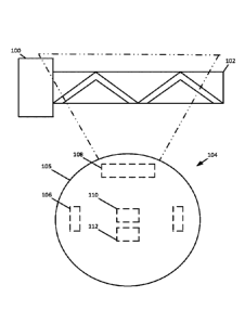
[0017] FIG. 1 shows a schematic view of an optical beacon 100 emitting light
(e.g., infrared
light) that defines at least one optical identifier 102. At least a portion of
the optical identifier
102 is shown as extending transverse to a direction of movement of a robotic
cleaner 104 when
the robotic cleaner 104 is moving generally towards the optical beacon 100.
The optical
identifier 102 can be associated with an action of the robotic cleaner 104
such that, upon
detecting at least a portion of the optical identifier 102, the robotic
cleaner 104 is caused to
carry out the associated action. In other words, the optical identifier 102 is
associated with an
action capable of being carried out by the robotic cleaner 104 such that
detection of the optical
identifier 102 causes the robotic cleaner 104 to carry out the action
associated therewith.
[0018] The robotic cleaner 104 includes a body 105, one or more driven wheels
106 (shown in
hidden lines) configured to urge the body 105 across a surface to be cleaned
(e.g., a floor), at
least one camera 108 (shown in hidden lines) (e.g., a monocular or stereo
camera oriented in a
forward, upward, or downward direction) coupled to the body 105 and configured
such that at
least a portion of the optical identifier 102 can be detected using the camera
108, and at least
one processor 110 (shown in hidden lines) coupled to at least one memory 112
(shown in
hidden lines), the processor 110 being configured to execute one or more
instructions stored in
the memory 112, the one or more instructions causing the robotic cleaner 104
to carry out one
or more actions. For example, when the optical identifier 102 is detected
using the camera 108,
the processor 110 can cause the robotic cleaner 104 to carry out an action
associated with the
detected optical identifier 102. The actions may include one or more of a
navigation action
(e.g., an action causing the robotic cleaner 104 to avoid or enter an area), a
cleaning action
(e.g., an action causing the robotic cleaner to change a cleaning behavior
such as adjusting a
3
CA 03121163 2021-05-26
WO 2020/112940
PCT/US2019/063518
suction force and/or brush roll speed), a mapping action (e.g., loading a map
associated with
the detected optical identifier 102 or the associating of a current map with
the detected optical
identifier 102), and/or any other action.
[0019] In some instances, the optical beacon 100 can include one or more
batteries for
powering the optical beacon 100 such that the optical beacon 100 can generate
the light that
defines the optical identifier. The one or more batteries may be rechargeable.
Additionally, or
alternatively, the optical beacon 100 can be configured to electrically couple
to an electrical
grid (e.g., via a power outlet in a household).
[0020] FIG. 2 shows a schematic example of a floor plan having a first room
200 separated
from a second room 202 by a wall 204. As shown, an optical beacon 206, which
may be an
example of the optical beacon 100 of FIG. 1, is disposed within an opening 208
(e.g., a
doorway) in the wall 204. The optical beacon 206 is configured to generate at
least a first
optical identifier 210 and a second optical identifier 212. The first and
second optical
identifiers 210 and 212 may have a substantially linear configuration and
extend in a direction
away from the optical beacon 206. However, other configurations are possible
(e.g., one or
more of the first and second optical identifiers may extend at least partially
around the optical
beacon 206). Each of the optical identifiers 210 and 212 may have a
corresponding action
capable of being carried out by the robotic cleaner 104 associated therewith.
[0021] For example, the first optical identifier 210 may correspond to a
navigation action (e.g.,
correspond to an action that causes the robotic cleaner 104 to pass through
the opening 208)
and the second optical identifier 212 may correspond to a cleaning action
(e.g., correspond to
a suction power or brush roll rotational speed) or a mapping action (e.g.,
loading of a map
associated with the second optical identifier 212). In some instances, a
plurality of actions may
be associated with the second optical identifier 212, wherein at least one of
the plurality of
actions are further based, at least in part, on the order of detection of the
first and second optical
identifiers 210 and 212. For example, if the second optical identifier 212 is
detected before the
first optical identifier 210, the second optical identifier 212 may correspond
to a navigation
action (e.g., an action causing the robotic cleaner 104 to not pass through
the opening 208).
However, if the first optical identifier 210 is detected before the second
optical identifier 212,
the second optical identifier 212 may correspond to a cleaning action. In
other words, the
optical beacon 206 may be configured to function as a one directional gateway
for the opening
208.
[0022] Additionally, or alternatively, a plurality of actions may be
associated with one or more
of the first or second optical identifiers 210 and 212, wherein at least one
action is further
4
CA 03121163 2021-05-26
WO 2020/112940
PCT/US2019/063518
associated with one or more predetermined criteria (e.g., a cleaning duration,
a distance
traveled, remaining battery power, and/or the like). For example, the first
and/or second optical
identifiers 210 and 212 may correspond to a navigation action (e.g., an action
causing the
robotic cleaner 104 to not pass through the opening 208) until a predetermined
criteria is met
(e.g., battery power remaining falls below a threshold, cleaning duration
exceeds a threshold,
distance traveled exceeds a threshold, and/or the like). In other words, the
optical beacon 206
can be configured to prevent the robotic cleaner 104 from passing between the
first and second
rooms 200 and 202 until predetermined criteria are met.
[0023] FIG. 3 shows a schematic cross-sectional view of an optical beacon 300,
which may be
an example of the optical beacon 100 of FIG. 1. The optical beacon 300 may be
configured to
generate one or more linear optical identifiers 302 (e.g., the first and/or
second optical
identifiers 210 and 212 of FIG. 2). As shown, the optical beacon 300 includes
an optical emitter
303 (e.g., a light emitting diode) at least partially disposed within a
housing 301 of the optical
beacon 300 and configured to emit light (e.g., infrared light) into an optical
identifier generator
304. As such, the optical emitter 303 may generally be described as being
optically coupled to
the optical identifier generator 304. The optical identifier generator 304 is
configured such that
light incident on the optical identifier generator 304 is shaped to form the
linear optical
identifier 302.
[0024] For example, the optical identifier generator 304 can be configured to
shape the light
passing therethrough such that the light linearly extends across a surface
(e.g., a floor, wall,
ceiling, and/or any other surface). In these instances, the optical identifier
generator 304
includes a material having one or more opaque portions (non-light transmissive
portions) and
one or more light transmissive portions such that the light passing
therethrough is shaped to
define the optical identifier 302. For example, the shaped light may define a
zig-zag shape, a
curved shape, a spotted pattern, and/or any other shape/pattern.
[0025] The optical identifier generator 304 may include a film having light
transmissive and
opaque portions such that light passes therethrough according to an identifier
defined by the
film. Additionally, or alternatively, the optical identifier generator 304 may
include a light
guide having a plurality of light emission portions configured to cooperate to
project the optical
identifier 302. Additionally, or alternatively, the optical identifier
generator 304 may include
a diffractive optical element. Additionally, or alternatively, the optical
identifier generator 304
may include a prism.
[0026] FIG. 4 shows a schematic example of a floor plan having a first room
400 separated
from a second room 402 by a wall 404 having an opening 405 (e.g., a doorway).
As shown,
CA 03121163 2021-05-26
WO 2020/112940
PCT/US2019/063518
an optical beacon 406, which may be an example of the optical beacon 100 of
FIG. 1, is
disposed within the second room 402. The optical beacon 406 is configured to
generate at least
one optical identifier 408 that extends around the optical beacon 406,
defining a bounded area
407. For example, the optical identifier 408 may have an annular shape, a
square shape, a
rectangular shape, a pentagonal shape, a triangular shape, an octagonal shape,
and/or any other
shape.
[0027] Upon detecting the optical identifier 408, the robotic cleaner 104 may
be caused to carry
out one or more actions (e.g., a navigation action, a cleaning action, a
mapping action, and/or
any other action) associated with the optical identifier 408. For example, the
optical beacon
406 may be disposed in a portion of the second room 402 such that the bounded
area 407
defines an area in which the robotic cleaner 104 is not to travel. By way of
further example,
the optical beacon may be disposed in a portion of the second room 402 such
that the bounded
area 407 defines an area in which the robotic cleaner 104 is caused to perform
enhanced
cleaning (e.g., increases the suction power and/or brush roll speed).
[0028] In some instances, the optical beacon 406 may be configured to generate
a plurality of
optical identifiers 408. As discussed in relation to FIG. 2, the action caused
to be carried out
by the robotic cleaner 104 may be based, at least in part, on the order in
which the robotic
cleaner 104 detects each of the optical identifiers 408.
[0029] FIG. 5 shows a schematic floor plan of a room 500 having a docking
station 502
disposed therein, the docking station 502 may be an example of the optical
beacon 406 of FIG.
4. The docking station 502 can be configured to electrically couple to the
robotic cleaner 104
such that one or more batteries of the robotic cleaner 104 can be recharged.
In some instances,
the docking station 502 can be configured to remove debris from a dust cup of
the robotic
cleaner 104.
[0030] As shown, the docking station 502 can be configured to generate at
least a first optical
identifier 504 and a second optical identifier 506. The first optical
identifier 504 can
correspond to a first action (e.g., a navigation action, a cleaning action, a
mapping action,
and/or any other action) and the second optical identifier 506 can correspond
to a second action
(e.g., a navigation action, a cleaning action, a mapping action, and/or any
other action). In
some instances, the action associated with the first and second optical
identifiers 504 and 506
may be based, at least in part, on the order in which the first and second
optical identifiers 504
and 506 are detected. For example, the first optical identifier 504 can
correspond to a
navigation action that causes the robotic cleaner 104 to enter a bounded area
508 defined by
the first and second optical identifiers 504 and 506. When the first optical
identifier 504 is
6
CA 03121163 2021-05-26
WO 2020/112940
PCT/US2019/063518
detected before the second optical identifier 506, the second optical
identifier 506 may indicate,
for example, a docking station type (e.g., whether or not the docking station
is capable of
removing debris from a dust cup of the robotic cleaner). However, when the
second optical
identifier 506 is detected before the first optical identifier 504, the second
optical identifier 506
may correspond to a navigation action (e.g., an action preventing the robotic
cleaner 104 from
exiting the bounded area 508). As such, the robotic cleaner 104 may be kept
proximate to the
docking station 502 such that the robotic cleaner 104 can engage the docking
station 502.
[0031] Additionally, or alternatively, one or more of the first and second
optical identifiers 504
and 506 can be associated with a plurality of actions. At least one of the
actions may be further
associated with one or more predetermined criteria (e.g., a cleaning duration,
a distance
traveled, remaining battery power, and/or the like). For example, the second
optical identifier
506 may correspond to a navigation action that prevents the robotic cleaner
104 from exiting
the bounded area 508 if a measure of battery power is below a threshold.
[0032] FIG. 6 shows a schematic cross-sectional view of an optical beacon 600,
which may be
an example of the optical beacon 100 of FIG. 1. The optical beacon 600 is
configured to
generate an optical identifier 602 that extends annularly around the optical
beacon 600. As
shown, the optical beacon 600 includes an optical emitter 604 (e.g., a light
emitting diode) at
least partially disposed within a housing 601 of the optical beacon 600 and
configured to emit
light (e.g., infrared light) along a light path 606. The light path 606
extends from the optical
emitter 604 and is incident on an optical identifier generator 608. The light
path 606 extends
from the optical identifier generator 608 and into an environment surrounding
the optical
beacon 600.
[0033] The optical identifier generator 608 can be configured such that light
incident on the
optical identifier generator 608 is shaped to have an identifier that is
projected into the
surrounding environment (e.g., a floor, wall, ceiling, and/or any other
surface). For example,
the optical identifier generator 608 may include a prism, a conical mirror
(e.g., having one or
more non-reflective portions defining a shape of the optical identifier to be
generated), a
diffractive optical element, and/or any other optical element capable of
generating an identifier.
In some instances, the optical identifier generator 608 may include a conical
mirror configured
to direct light into one or more prisms, one or more films having opaque and
transmissive
portions defining the identifier, one or more diffractive optical elements,
and/or any other
optical element capable of generating an identifier.
[0034] FIG. 7 shows a flow chart of an example method 700 of carrying out an
action using a
robotic cleaner, such as the robotic cleaner 104 of FIG. 1, in response to
detecting at least a
7
CA 03121163 2021-05-26
WO 2020/112940
PCT/US2019/063518
portion of an optical identifier, such as the optical identifier 102 of FIG.
1. The method 700
may include a step 702. The step 702 may include detecting, using a camera of
the robotic
cleaner, at least a portion of an optical identifier projected onto a surface
(e.g., a floor, wall,
ceiling, and/or any other surface) by an optical beacon. For example, the
optical identifier may
be projected onto a surface to be cleaned.
[0035] The method 700 may also include a step 704. The step 704 may include
determining
whether the detected optical identifier is known based, at least in part, on a
comparison of at
least a portion of the detected identifier to one or more known identifiers
stored in a memory
of the robotic cleaner. In response to the comparison indicating that the
detected identifier
corresponds to a known identifier, determining at least one action (e.g., a
cleaning action, a
navigation action, a mapping action, and/or any other action) associated with
the detected
identifier. In some instances, the detected identifier may be determined to
have a plurality of
actions associated therewith. In response to the comparison indicating that
the detected
identifier does not correspond to a known identifier (i.e., the detected
identifier is unknown),
the robotic cleaner may be configured to associate the detected identifier
with at least one action
(e.g., a cleaning action, a navigation action, a mapping action, and/or any
other action). For
example, the robotic cleaner may be configured to query a user to determine
which action to
associate with the detected identifier.
[0036] The method 700 may also include a step 706. The step 706 may include
determining
whether at least a portion of a plurality of optical identifiers are detected
within a predetermined
time period (e.g., 0.5 seconds, 1 second, 2, seconds, and/or any other
predetermined time
period). For example, when a plurality of optical identifiers are detected
(each being known
and having at least one action associated therewith), the robotic cleaner can
be configured to
determine whether one or more of the actions associated with one or more of
the plurality of
optical identifiers are also associated with an order in which the first and
second optical
identifiers are detected. If the actions are determined to also be associated
with an order of
detection, the order in which the optical identifiers are detected can be
determined and the
robotic cleaner can be configured to carry out an action associated with the
order of detection
and corresponding optical identifier. In other words, the robotic cleaner can
be caused to carry
out one or more actions associated with the detected identifiers based, at
least in part, on an
order of detection. If the actions are not determined to be associated with an
order of detection,
the robotic cleaner can be configured to carry out each action associated with
the respective
optical identifiers and/or associate an action with one or more of the
detected identifiers that is
8
CA 03121163 2021-05-26
WO 2020/112940
PCT/US2019/063518
based, at least in part, on the order of detection (e.g., in response to
querying a user of the
robotic cleaner).
[0037] The method 700 may also include a step 708. The step 708 may include
determining
whether predetermined criteria (e.g., a cleaning duration, a distance
traveled, remaining battery
power, and/or the like) are associated with an action corresponding to the
detected optical
identifier. If predetermined criteria are associated with the action, the
robotic cleaner can be
configured to carry out the action only if the predetermined criteria are met.
[0038] The method 700 may also include a step 710. The step 710 can include
causing the
robotic cleaner to carry out the one or more actions associated with the one
or more optical
identifiers.
[0039] The method 700 can be embodied as instructions in at least one non-
transitory computer
readable medium such that, when the instructions are executed by one or more
processors, the
method 700 can be caused to be carried out. In some instances, one or more
steps of the method
700 can be embodied in circuitry (e.g., an application specific integrated
circuit). As such, the
method 700 can be carried out using any combination of software, firmware,
and/or hardware.
[0040] FIG. 8 shows a schematic example of a main beacon 800 and a satellite
beacon 802
disposed within a room 803. The main beacon 800 and the satellite beacon 802
may be
examples of the optical beacon 100 of FIG. 1. The main beacon 800 can be
configured to be
electrically coupled to an electrical grid via a power outlet 804. In some
instances, the main
beacon 800 can be a docking station configured to recharge one or more
rechargeable batteries
of the robotic cleaner 104. The satellite beacon 802 can be configured to be
powered by one
or more rechargeable batteries 806 (shown in hidden lines).
[0041] The main beacon 800 can be configured to charge the one or more
rechargeable
batteries 806 of the satellite beacon 802. For example, the main beacon 800
can include a
plurality of main charging contacts 808 configured to electrically couple to a
plurality of
satellite charging contacts 810 disposed on the satellite beacon 802.
Additionally, or
alternatively, the one or more rechargeable batteries 806 can be recharged by
electrically
coupling the satellite beacon 802 to the power outlet 804 via a power cable.
[0042] In some instances, the robotic cleaner 104 can be configured to
recharge the satellite
beacon 802. For example, if, when performing a cleaning operation, the robotic
cleaner 104
detects that an intensity of the light defining a satellite optical identifier
812 has fallen below a
threshold, the robotic cleaner 104 can electrically couple to the satellite
beacon 802 to recharge
the one or more rechargeable batteries 806 of the satellite beacon 802 (e.g.,
after completion of
the cleaning operation) using one or more rechargeable batteries of the
robotic cleaner 104. As
9
CA 03121163 2021-05-26
WO 2020/112940
PCT/US2019/063518
such, the one or more rechargeable batteries 806 may be recharged without
involving a user of
the robotic cleaner 104.
[0043] An example of an optical beacon, consistent with the present
disclosure, may include a
housing, an optical emitter at least partially disposed within the housing,
and an optical
identifier generator optically coupled to the optical emitter. Light incident
on the optical
identifier generator may be shaped into at least one optical identifier. The
optical identifier
may be associated with an action capable of being carried out by a robotic
cleaner such that
detection of the optical identifier by the robotic cleaner causes the robotic
cleaner to carry out
the action.
[0044] In some instances, the optical identifier generator may include a
diffractive optical
element. In some instances, the optical identifier generator may include a
prism. In some
instances, the at least one optical identifier may include a plurality of
optical identifiers, each
optical identifier having a corresponding action associated therewith. In some
instances, the
optical identifier may be substantially linear. In some instances, the optical
identifier may
extend around the housing, defining a bounded area. In some instances, the
optical identifier
may extend annularly around the housing. In some instances, the action may be
one or more
of a cleaning action or a navigation action. In some instances, the optical
beacon may further
include one or more rechargeable batteries. In some instances, the one or more
rechargeable
batteries may be recharged using a docking station for the robotic cleaner,
the docking station
being electrically coupled to an electrical grid via a power outlet. In some
instances, the one
or more rechargeable batteries may be recharged using the robotic cleaner.
[0045] An example of a robotic cleaner, consistent with the present
disclosure, may include a
body, one or more driven wheels configured to urge the body across a surface
to be cleaned, a
camera coupled to the body, and at least one processor configured execute one
or more
instructions stored in at least one memory. Upon executing the one or more
instructions the
processor may cause the robotic cleaner to carry out operations including
detecting at least one
optical identifier projected onto the surface to be cleaned by an optical
beacon, determining
whether the detected optical identifier is known based, at least in part, on a
comparison of at
least a portion of the detected optical identifier to one or more known
optical identifiers stored
in the memory, in response to determining that the detected optical identifier
is known,
determining at least one action associated with the detected optical
identifier, and causing the
robotic cleaner to carry out the determined action.
[0046] In some instances, the operations may further include, in response to
determining that
the optical identifier is unknown, causing the robotic cleaner to associate at
least one action
CA 03121163 2021-05-26
WO 2020/112940
PCT/US2019/063518
with the detected optical identifier. In some instances, a plurality of
optical identifiers may be
detected, each of the optical identifiers being known and having at least one
respective action
associated therewith. In some instances, at least one of the plurality of
optical identifiers may
have a plurality of actions associated therewith. In some instances, the
operations may further
include determining an order of detection for the plurality of optical
identifiers. In some
instances, the robotic cleaner may be caused to carry out one or more of the
plurality of actions
associated with at least one of the optical identifiers based, at least in
part, on the order of
detection. In some instances, the optical identifier may be substantially
linear. In some
instances, the optical identifier may extend around the optical beacon,
defining a bounded area.
In some instances, the optical identifier may extend annularly around the
optical beacon.
[0047] While the principles of the invention have been described herein, it is
to be understood
by those skilled in the art that this description is made only by way of
example and not as a
limitation as to the scope of the invention. Other embodiments are
contemplated within the
scope of the present invention in addition to the exemplary embodiments shown
and described
herein. Modifications and substitutions by one of ordinary skill in the art
are considered to be
within the scope of the present invention, which is not to be limited except
by the following
claims.
11