Note: Descriptions are shown in the official language in which they were submitted.
CA 03121215 2021-05-26
DESCRIPTION
Title of Invention: HEAT UTILIZATION SYSTEM, AND HEAT GENERATING
DEVICE
Technical Field
[ 0001 ]
The present invention relates to a heat utilization system
and a heat generating device.
Background Art
[ 0002 ]
In recent years, a heat generation phenomenon in which heat
is generated by occluding and discharging hydrogen using a hydrogen
storage metal or the like is reported (see, for example, Non-Patent
Literature 1) . Hydrogen can be generated from water and is thus
inexhaustible and inexpensive as a resource, and does not generate
a greenhouse gas such as carbon dioxide and is thus clean energy.
Unlike a nuclear fission reaction, the heat generation phenomenon
using the hydrogen storage metal or the like is safe since there
is no chain reaction. Heat generated by occluding and discharging
hydrogen can be utilized as it is, and can be further utilized
by being converted into electric power. Therefore, the heat is
expected as an effective heat energy source.
Citation List
1
Date Recue/Date Received 2021-05-26
CA 03121215 2021-05-26
Non-Patent Literature
[0003]
Non-Patent Literature 1: A. Kitamura. et .al "Brief summary
of latest experimental results with a mass-flow calorimetry system
for anomalous heat effect of nano-composite metals under D(H) -gas
charging" CURRENT SCIENCE, VOL. 108, NO. 4, p.589-593, 2015
Summary of Invention
Technical Problem
[0004]
However, a heat energy source is still mainly obtained from
thermal power generation or nuclear power generation. Therefore,
from the viewpoint of environmental problems and energy problems,
there is a demand for a novel heat utilization system and heat
generating device that utilize an inexpensive, clean, and safe
heat energy source and that have not been disclosed in the related
art.
[0005]
Therefore, an object of the invention is to provide a novel
heat utilization system and heat generating device that utilize
an inexpensive, clean, and safe heat energy source.
Solution to Problem
[0006]
A heat utilization system according to the invention
includes a heat-generating element configured to generate heat
2
Date Recue/Date Received 2021-05-26
CA 03121215 2021-05-26
by occluding and discharging hydrogen, a sealed container having
a first chamber and a second chamber partitioned by the
heat-generating element, a temperature adjustment unit configured
to adjust a temperature of the heat-generating element, and a heat
utilization device configured to utilize a heat medium heated by
the heat generated by a heat-generating element. The first
chamber and the second chamber have different hydrogen pressures.
The heat-generating element includes a support element made of
at least one of a porous body, a hydrogen permeable film, and a
proton conductor, and a multilayer film supported by the support
element. The multilayer film has a first layer made of a hydrogen
storage metal or a hydrogen storage alloy and having a thickness
of less than 1000 nm and a second layer made of a hydrogen storage
metal different from that of the first layer, a hydrogen storage
alloy different from that of the first layer, or ceramics and having
a thickness of less than 1000 nm.
[0007]
Another heat utilization system according to the invention
includes a heat-generating element configured to generate heat
by occluding and discharging hydrogen, a sealed container
accommodating the heat-generating element, a gas introduction
unit configured to introduce a hydrogen-based gas into the sealed
container, a gas discharge unit configured to discharge the
hydrogen-based gas inside the sealed container to an outside of
the sealed container, a temperature sensor configured to detect
a temperature of the heat-generating element, a heat generating
3
Date Recue/Date Received 2021-05-26
CA 03121215 2021-05-26
cell provided in the gas introduction unit and including a heater
configured to heat the heat-generating element by heating the
hydrogen-based gas circulating through the gas introduction unit,
and a control unit configured to adjust the temperature of the
heat-generating element by controlling the heater based on the
temperature detected by the temperature sensor. The sealed
container has a first chamber and a second chamber partitioned
by the heat-generating element. The first chamber and the second
chamber have different hydrogen pressures. The heat-generating
element includes a support element made of at least one of a porous
body, a hydrogen permeable film, and a proton conductor, and a
multilayer film supported by the support element. The multilayer
film has a first layer made of a hydrogen storage metal or a hydrogen
storage alloy and having a thickness of less than 1000 nm and a
second layer made of a hydrogen storage metal different from that
of the first layer, a hydrogen storage alloy different from that
of the first layer, or ceramics and having a thickness of less
than 1000 nm.
[0008]
A heat generating device according to the invention includes
a heat-generating element configured to generate heat by occluding
and discharging hydrogen, a sealed container having a first chamber
and a second chamber partitioned by the heat-generating element,
and a temperature adjustment unit configured to adjust a
temperature of the heat-generating element. The first chamber and
the second chamber have different hydrogen pressures. The
4
Date Recue/Date Received 2021-05-26
CA 03121215 2021-05-26
heat-generating element includes a support element made of at least
one of a porous body, a hydrogen permeable film, and a proton
conductor, and a multilayer film supported by the support element.
The multilayer film has a first layer made of a hydrogen storage
metal or a hydrogen storage alloy and having a thickness of less
than 1000 nm and a second layer made of a hydrogen storage metal
different from that of the first layer, a hydrogen storage alloy
different from that of the first layer, or ceramics and having
a thickness of less than 1000 nm.
Advantageous Effects of Invention
[0009]
According to the invention, since the heat-generating
element that generates heat by occluding and discharging hydrogen
is utilized as a heat energy source, inexpensive, clean, and safe
energy can be supplied.
Brief Description of Drawings
[0010]
Fig. 1 is a schematic diagram showing a heat utilization
system according to a first embodiment.
Fig. 2 is a cross-sectional view showing a structure of a
heat-generating element having a first layer and a second layer.
Fig. 3 is a diagram showing generation of excess heat.
Fig. 4 is a diagram showing a function of a heat generating
device.
Date Recue/Date Received 2021-05-26
CA 03121215 2021-05-26
Fig. 5 is a diagram showing a heat-generating element having
a multilayer film on both surfaces according to Modification 1.
Fig. 6 is a diagram showing a heat-generating element having
a first layer, a second layer, and a third layer according to
Modification 2.
Fig. 7 is a diagram showing a heat-generating element having
a first layer, a second layer, a third layer, and a fourth layer
according to Modification 3.
Fig. 8 is a graph showing a relationship between a ratio
of layer thicknesses of the multilayer film and the excess heat.
Fig. 9 is a graph showing a relationship between the number
of layers of the multilayer film and the excess heat.
Fig. 10 is a graph showing a relationship between a material
of the multilayer film and the excess heat.
Fig. 11 is a cross-sectional view showing a heat-generating
element having a bottomed cylindrical shape.
Fig. 12 is a schematic diagram showing a heat utilization
system according to Modification 4.
Fig. 13 is a cross-sectional view showing a heat-generating
element including a support element having a columnar shape.
Fig. 14 is a schematic diagram showing a heat utilization
system according to Modification 5.
Fig. 15 is a schematic diagram showing a heat utilization
system according to Modification 6.
Fig. 16 is a schematic diagram showing a heat utilization
system according to Modification 7.
6
Date Recue/Date Received 2021-05-26
CA 03121215 2021-05-26
Fig. 17 is a schematic diagram showing a heat utilization
system according to Modification 8.
Fig. 18 is a schematic diagram showing a heat utilization
system according to Modification 9.
Fig. 19 is a schematic diagram showing a heat utilization
system according to Modification 10.
Fig. 20 is a schematic diagram showing a heat utilization
system according to Modification 11.
Fig. 21 is a schematic diagram showing a heat utilization
system according to Modification 12.
Fig. 22 is a schematic diagram showing a heat utilization
system according to Modification 13.
Fig. 23 is a schematic diagram showing a heat utilization
system according to Modification 14.
Fig. 24 is a diagram showing a nozzle portion having a
plurality of ejection ports.
Fig. 25 is a cross-sectional view showing a cylindrical
heat-generating element having two open ends.
Fig. 26 is a schematic diagram showing a heat utilization
system according to Modification 15.
Fig. 27 is a schematic diagram showing a heat utilization
system according to Modification 16.
Fig. 28 is a diagram showing a first mode of a hydrogen
pressure control unit.
Fig. 29 is a diagram showing a second mode of the hydrogen
pressure control unit.
7
Date Recue/Date Received 2021-05-26
CA 03121215 2021-05-26
Fig. 30 is a schematic diagram showing a heat utilization
system according to Modification 17.
Fig. 31 is a diagram showing a function of a heat generating
device according to Modification 17.
Fig. 32 is a schematic diagram showing a heat utilization
system according to Modification 18.
Fig. 33 is a schematic diagram showing a heat utilization
system according to Modification 19.
Fig. 34 is a diagram showing a gas introduction branch pipe.
Fig. 35 is a schematic diagram showing a heat utilization
system according to Modification 20.
Fig. 36 is a schematic diagram showing a heat utilization
system according to Modification 21.
Fig. 37 is a diagram showing a connection between a heat
generating cell and a hydrogen circulation line.
Fig. 38 is a schematic diagram showing a heat generating
device according to Modification 22.
Fig. 39 is a schematic diagram showing a heat generating
device according to Modification 23.
Fig. 40 is a schematic diagram showing a heat generating
device according to Modification 24.
Fig. 41 is a schematic diagram showing a heat generating
device according to Modification 25.
Fig. 42 is across-sectional view showing the heat generating
device according to Modification 25.
Fig. 43 is a schematic diagram showing a heat utilization
8
Date Recue/Date Received 2021-05-26
CA 03121215 2021-05-26
system according to Modification 26.
Fig. 44 is a graph showing a relationship among a hydrogen
permeation amount, a hydrogen supply pressure, and a sample
temperature in a reference experiment.
Fig. 45 is a graph showing a relationship between a sample
temperature and input electric power in the reference experiment.
Fig. 46 is a graph showing a relationship between a
heat-generating element temperature and excess heat according to
Experimental Example 26.
Fig. 47 is a graph showing a relationship between a
heat-generating element temperature and excess heat according to
Experimental Example 27.
Fig. 48 is a schematic diagram showing a heat utilization
system according to a second embodiment.
Fig. 49 is a schematic diagram showing a heat generating
device according to Modification 1 of the second embodiment.
Fig. 50 shows a front view and a plan view of a
heat-generating element unit according to Modification 2 of the
second embodiment.
Fig. 51 is a cross-sectional view showing the
heat-generating element unit according to Modification 2 of the
second embodiment.
Fig. 52 is a schematic diagram showing a heat generating
device according to Modification 3 of the second embodiment.
Description of Embodiments
9
Date Recue/Date Received 2021-05-26
CA 03121215 2021-05-26
[0011]
[First embodiment]
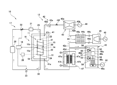
As shown in Fig. 1, a heat utilization system 10 includes
a heat generating device 11 and a heat utilization device 12. The
heat utilization system 10 heats a heat medium to be described
later by heat generated by the heat generating device 11, and
operates the heat utilization device 12 using the heated heat
medium as a heat source.
[0012]
The heat generating device 11 includes a heat-generating
element 14, a sealed container 15, a temperature adjustment unit
16, a hydrogen circulation line 17, and a control unit 18.
[0013]
The heat-generating element 14 is accommodated in the sealed
container 15 and is heated by a heater 16b of the temperature
adjustment unit 16 to be described later. The heat-generating
element 14 generates heat (hereinafter, referred to as excess heat)
having a temperature equal to or higher than a heating temperature
of the heater 16b by occluding and discharging hydrogen. The
heat-generating element 14 heats the heat medium to a temperature
within a range of, for example, 50 C or higher and 1500 C or lower
by generating the excess heat. In this example, the
heat-generating element 14 has a plate shape having a front surface
and a back surface. A detailed configuration of the
heat-generating element 14 will be described later with reference
to another drawing.
Date Recue/Date Received 2021-05-26
CA 03121215 2021-05-26
[0014]
The sealed container 15 is a hollow container, and
accommodates the heat-generating element 14 therein. The sealed
container 15 is made of stainless steel or the like. In this
example, the sealed container 15 has a shape having a longitudinal
direction parallel to a direction orthogonal to the front surface
or the back surface of the heat-generating element 14. An
installation portion 20 for installing the heat-generating
element 14 is provided inside the sealed container 15.
[0015]
The sealed container 15 has a first chamber 21 and a second
chamber 22 partitioned by the heat-generating element 14. The
first chamber 21 is defined by the front surface that is one surface
of the heat-generating element 14 and an inner surface of the sealed
container 15. The first chamber 21 has an introduction port 23
connected to the hydrogen circulation line 17 to be described later.
A hydrogen-based gas circulating through the hydrogen circulation
line 17 is introduced into the first chamber 21 through the
introduction port 23. The second chamber 22 is formed by the back
surface that is the other surface of the heat-generating element
14 and the inner surface of the sealed container 15. The second
chamber 22 has a recovery port 24 connected to the hydrogen
circulation line 17. The hydrogen-based gas in the second chamber
22 is recovered to the hydrogen circulation line 17 through the
recovery port 24.
[0016]
11
Date Recue/Date Received 2021-05-26
CA 03121215 2021-05-26
The first chamber 21 is pressurized by introducing the
hydrogen-based gas. The second chamber 22 is depressurized by
recovering the hydrogen-based gas. Accordingly, a hydrogen
pressure in the first chamber 21 is higher than a hydrogen pressure
in the second chamber 22. The hydrogen pressure in the first
chamber 21 is, for example, 100 [kPa]. The hydrogen pressure in
the second chamber 22 is, for example, 1 x 10⁻⁴ [Pa] or less. The
second chamber 22 may be in a vacuum state. In this manner, the
first chamber 21 and the second chamber 22 have different hydrogen
pressures. Therefore, the inside of the sealed container 15 is
in a state in which a pressure difference is generated between
two sides of the heat-generating element 14.
[0017]
When the pressure difference is generated between the two
sides of the heat-generating element 14, a hydrogen molecule
contained in the hydrogen-based gas is adsorbed on the one surface
(the front surface) of the heat-generating element 14 at a high
pressure side, and the hydrogen molecule is dissociated into two
hydrogen atoms. The hydrogen atoms obtained by dissociation
infiltrate into the heat-generating element 14. That is, hydrogen
is occluded into the heat-generating element 14. The hydrogen
atoms diffuse into the heat-generating element 14 and go through
from one surface to the other surface of the heat-generating
element 14. On the other surface (the back surface) of the
heat-generating element 14 at a low pressure side, the hydrogen
atoms that have gone through the heat-generating element 14 are
12
Date Recue/Date Received 2021-05-26
CA 03121215 2021-05-26
recombined with each other and discharged as a hydrogen molecule.
That is, hydrogen is discharged from the heat-generating element
14. In this manner, hydrogen permeates through the
heat-generating element 14 from the high pressure side to the low
pressure side. "Permeate" refers to that hydrogen occluded from
one surface of the heat-generating element is discharged from the
other surface of the heat-generating element. The
heat-generating element 14 to be described in detail later
generates heat by occluding hydrogen, and generates heat also by
discharging hydrogen. Therefore, the heat-generating element 14
generates heat by permeation of hydrogen. In the following
description, "hydrogen permeates through" the heat-generating
element may be described as "a hydrogen-based gas permeates
through" the heat-generating element.
[0018]
A pressure sensor (not shown) that detects an internal
pressure of the first chamber 21 is provided inside the first
chamber 21. A pressure sensor (not shown) that detects an internal
pressure of the second chamber 22 is provided inside the second
chamber 22. The pressure sensors provided in the first chamber
21 and the second chamber 22 are electrically connected with the
control unit 18, and output a signal corresponding to the detected
pressure to the control unit 18.
[0019]
The temperature adjustment unit 16 adjusts a temperature
of the heat-generating element 14 and maintains the
13
Date Recue/Date Received 2021-05-26
CA 03121215 2021-05-26
heat-generating element 14 at an appropriate temperature for heat
generation. An appropriate temperature for heat generation in the
heat-generating element 14 is within a range of, for example, 50 C
or higher and 1500 C or lower.
[0020]
The temperature adjustment unit 16 includes a temperature
sensor 16a and the heater 16b. The temperature sensor 16a detects
the temperature of the heat-generating element 14. The
temperature sensor 16a is, for example, a thermocouple, and is
provided in the installation portion 20 of the sealed container
15. The temperature sensor 16a is electrically connected with the
control unit 18, and outputs a signal corresponding to the detected
temperature to the control unit 18.
[0021]
The heater 16b heats the heat-generating element 14. The
heater 16b is, for example, an electric heating wire of an electric
resistance heat generating type, and is wound around an outer
periphery of the sealed container 15. The heater 16b is
electrically connected with a power supply 26, and generates heat
by inputting electric power from the power supply 26. The heater
16b may be an electric furnace that covers the outer periphery
of the sealed container 15.
[0022]
The hydrogen circulation line 17 is provided outside the
sealed container 15, connects the first chamber 21 and the second
chamber 22, and circulates a hydrogen-based gas containing
14
Date Recue/Date Received 2021-05-26
CA 03121215 2021-05-26
hydrogen between an inside and an outside of the sealed container
15. The hydrogen circulation line 17 includes a buffer tank 28,
an introduction line 29, a recovery line 30, and a filter 31.
Although not shown in Fig. 1, the heat utilization system 10
includes a supply line for supplying the hydrogen-based gas to
the hydrogen circulation line 17, and an exhaust line for
exhausting the hydrogen-based gas from the hydrogen circulation
line 17. For example, the hydrogen-based gas is supplied from the
supply line to the hydrogen circulation line 17 when an operation
of the heat utilization system 10 is started, and the
hydrogen-based gas in the hydrogen circulation line 17 is exhausted
to the exhaust line when the operation of the heat utilization
system 10 is stopped.
[0023]
The buffer tank 28 stores the hydrogen-based gas. The
hydrogen-based gas is a gas containing isotopes of hydrogen. As
the hydrogen-based gas, at least one of a deuterium gas and a
protium gas is used. The protium gas includes a mixture of
naturally occurring protium and deuterium, that is, a mixture in
which an abundance ratio of protium is 99.985% and an abundance
ratio of deuterium is 0.015%. A flow rate fluctuation of the
hydrogen-based gas is absorbed by the buffer tank 28.
[0024]
The introduction line 29 connects the buffer tank 28 and
the introduction port 23 of the first chamber 21, and introduces
the hydrogen-based gas stored in the buffer tank 28 into the first
Date Recue/Date Received 2021-05-26
CA 03121215 2021-05-26
chamber 21. The
introduction line 29 includes a pressure
adjustment valve 32. The pressure adjustment valve 32
depressurizes the hydrogen-based gas sent from the buffer tank
28 to a predetermined pressure. The pressure adjustment valve 32
is electrically connected with the control unit 18.
[0025]
The recovery line 30 connects the recovery port 24 of the
second chamber 22 and the buffer tank 28, recovers the
hydrogen-based gas that has permeated through the heat-generating
element 14 from the first chamber 21 to the second chamber 22,
and returns the recovered hydrogen-based gas to the buffer tank
28. The recovery line 30 includes a circulation pump 33. The
circulation pump 33 recovers the hydrogen-based gas in the second
chamber 22 to the recovery line 30, pressurizes the hydrogen-based
gas to a predetermined pressure, and sends the pressurized
hydrogen-based gas to the buffer tank 28. Examples of the
circulation pump 33 include a metal bellows pump. The circulation
pump 33 is electrically connected with the control unit 18.
[0026]
The filter 31 removes impurities contained in the
hydrogen-based gas. Here, a permeation amount of hydrogen
permeating through the heat-generating element 14 (hereinafter,
referred to as a hydrogen permeation amount) is determined by the
temperature of the heat-generating element 14, a pressure
difference between two sides of the heat-generating element 14,
and a surface state of the heat-generating element 14. When the
16
Date Recue/Date Received 2021-05-26
CA 03121215 2021-05-26
hydrogen-based gas contains impurities, the impurities may adhere
to a surface of the heat-generating element 14, and may deteriorate
the surface state of the heat-generating element 14. When the
impurities adhere to the surface of the heat-generating element
14, adsorption and dissociation of the hydrogen molecule on the
surface of the heat-generating element 14 are hindered, and the
hydrogen permeation amount decreases. Examples of impurities
that hinder the adsorption and dissociation of the hydrogen
molecule on the surface of the heat-generating element 14 include
water (including steam) , hydrocarbons (methane, ethane, methanol,
ethanol, and the like) , C, S, and Si. It is considered that water
is discharged from an inner wall or the like of the sealed container
15, or is obtained by reducing, by hydrogen, an oxide film contained
in a member provided inside the sealed container 15. It is
considered that hydrocarbons, C, S, and Si are discharged from
various members provided inside the sealed container 15.
Therefore, the filter 31 at least removes the impurities including
water (including steam) , hydrocarbons, C, S, and Si. The filter
31 removes the impurities contained in the hydrogen-based gas,
so that the hydrogen permeation amount through the heat-generating
element 14 can be prevented from decreasing.
[0027]
The control unit 18 controls an operation of each unit of
the heat utilization system 10. The control unit 18 mainly
includes, for example, an arithmetic device (a central processing
unit) , and a storage unit such as a read-only memory and a random
17
Date Recue/Date Received 2021-05-26
CA 03121215 2021-05-26
access memory. The arithmetic device executes various kinds of
arithmetic processings using a program, data, and the like stored
in the storage unit.
[0028]
The control unit 18 is electrically connected with the
temperature sensor 16a, the power supply 26, the pressure
adjustment valve 32, and the circulation pump 33. The control unit
18 controls an output of the excess heat generated by the
heat-generating element 14 by adjusting input electric power of
the heater 16b, a pressure of the sealed container 15, and the
like.
[0029]
The control unit 18 functions as an output control unit that
controls an output of the heater 16b based on the temperature
detected by the temperature sensor 16a. The control unit 18
controls the power supply 26 to adjust input electric power to
the heater 16b, thereby maintaining the heat-generating element
14 at an appropriate temperature for heat generation.
[0030]
The control unit 18 controls the pressure adjustment valve
32 and the circulation pump 33 to adjust a hydrogen pressure
difference generated between the first chamber 21 and the second
chamber 22, based on a pressure detected by a pressure sensor (not
shown) provided in each of the first chamber 21 and the second
chamber 22.
[0031]
18
Date Recue/Date Received 2021-05-26
CA 03121215 2021-05-26
The control unit 18 performs a hydrogen occluding step of
occluding hydrogen in the heat-generating element 14 and a hydrogen
discharging step of discharging hydrogen from the heat-generating
element 14. In the present embodiment, the control unit 18
simultaneously performs the hydrogen occluding step and the
hydrogen discharging step by generating a hydrogen pressure
difference between the first chamber 21 and the second chamber
22. The control unit 18 causes a pressure in the first chamber
21 to be higher than a pressure in the second chamber 22 by
introducing the hydrogen-based gas from the introduction line 29
to the first chamber 21 and recovering the hydrogen-based gas from
the second chamber 22 to the recovery line 30, and maintains a
state in which occluding of hydrogen on the front surface of the
heat-generating element 14 and discharging of hydrogen on the back
surface of the heat-generating element 14 are simultaneously
performed. "Simultaneously" in the present disclosure refers to
exact simultaneous or refers to a short period of time to an extent
that can be regarded as substantially simultaneous. Since
hydrogen continuously permeates through the heat-generating
element 14 by simultaneously performing the hydrogen occluding
step and the hydrogen discharging step, the excess heat can be
efficiently generated in the heat-generating element 14. The
control unit 18 may alternately repeat the hydrogen occluding step
and the hydrogen discharging step. That is, the control unit 18
may first perform the hydrogen occluding step to occlude hydrogen
in the heat-generating element 14, and thereafter perform the
19
Date Recue/Date Received 2021-05-26
CA 03121215 2021-05-26
hydrogen discharging step to discharge hydrogen occluded in the
heat-generating element 14. In this manner, the excess heat can
be generated by the heat-generating element 14 by alternately
repeating the hydrogen occluding step and the hydrogen discharging
step.
[0032]
In the heat generating device 11, when a hydrogen pressure
difference is generated between the first chamber 21 and the second
chamber 22 that sandwich the heat-generating element 14, hydrogen
permeates through the heat-generating element 14 and the excess
heat is generated.
[0033]
The heat utilization device 12 utilizes, as a heat source,
a heat medium heated by the heat of the heat-generating element
14. The heat medium may be a gas or a liquid, and preferably has
excellent heat conductivity and chemical stability. Examples of
the gas include a rare gas such as a helium gas and an argon gas,
a hydrogen gas, a nitrogen gas, steam, air, carbon dioxide, and
a gas for forming a hydride. Examples of the liquid include water,
a molten salt (such as KNO3(40%)-NaNO3(60%)), and a liquid metal
(such as Pb). Alternatively, the heat medium may be a heat medium
having mixed phases in which solid particles are dispersed in a
gas or a liquid. Examples of the solid particles include a metal,
a metal compound, an alloy, and ceramics. Examples of the metal
include copper, nickel, titanium, and cobalt. Examples of the
metal compound include an oxide, a nitride, and a silicide of the
Date Recue/Date Received 2021-05-26
CA 03121215 2021-05-26
above-described metals. Examples of the alloy include stainless
steel and chromium molybdenum steel. Examples of the ceramics
include alumina. In this example, a helium gas is used as the heat
medium.
[0034]
The heat utilization device 12 includes an accommodation
container 41, a heat medium circulation unit 42, a gas turbine
43, a steam generator 44, a steam turbine 45, a Stirling engine
46, and a thermoelectric converter 47. Although the heat
utilization device 12 includes the gas turbine 43, the steam
generator 44, the steam turbine 45, the Stirling engine 46, and
the thermoelectric converter 47 in Fig. 1, the heat utilization
device 12 may include any combination of these components.
[0035]
The accommodation container 41 is a hollow container, and
accommodates the sealed container 15 of the heat generating device
11 therein. The accommodation container 41 is made of ceramics,
stainless steel, or the like. In this example, the accommodation
container 41 has a shape having a longitudinal direction parallel
to a longitudinal direction of the sealed container 15. A material
of the accommodation container 41 is preferably a material having
an excellent heat insulation property. The accommodation
container 41 is covered with a heat insulation member 51 in order
to more reliably cut off heat exchange with the outside.
[0036]
The accommodation container 41 has an inlet port 41a and
21
Date Recue/Date Received 2021-05-26
CA 03121215 2021-05-26
an outlet port 41b that are connected with the heat medium
circulation unit 42 serving as a heat medium circulation line to
be described later. The heat medium is circulated through a gap
54 between the accommodation container 41 and the sealed container
15. The inlet port 41a is provided at one end of the accommodation
container 41 in the longitudinal direction. The outlet port 41b
is provided at the other end of the accommodation container 41
in the longitudinal direction. The gap 54 is formed by an inner
surface of the accommodation container 41 and an outer surface
of the sealed container 15.
[0037]
The heat medium circulation unit 42 circulates the heat
medium between an inside and an outside of the accommodation
container 41. In the
present embodiment, the heat medium
circulation unit 42 includes a first pipe 42a that connects the
accommodation container 41 and the gas turbine 43, a second pipe
42b that connects the gas turbine 43 and the steam generator 44,
a third pipe 42c that connects the steam generator 44 and the
Stirling engine 46, a fourth pipe 42d that connects the Stirling
engine 46 and the accommodation container 41, a pump 42e that causes
the heat medium to flow from the accommodation container 41 to
the first pipe 42a, and a heat medium flow rate control unit 42f
that adjusts a flow rate of the heat medium flowing out from the
accommodation container 41 to the first pipe 42a. The pump 42e
and the heat medium flow rate control unit 42f are provided in
the first pipe 42a. Examples of the pump 42e include a metal
22
Date Recue/Date Received 2021-05-26
CA 03121215 2021-05-26
bellows pump.
[0038]
The heat medium flowing out from the accommodation container
41 sequentially flows through the first pipe 42a, the second pipe
42b, the third pipe 42c, and the fourth pipe 42d, and is returned
to the accommodation container 41. Therefore, the heat medium
circulation unit 42 functions as a heat medium circulation line
through which the heat medium is circulated between the inside
and the outside of the accommodation container 41. The heat medium
heated by the heat generating device 11 inside the accommodation
container 41 flows through the heat medium circulation unit 42
serving as a heat medium circulation line, and is cooled
sequentially via the gas turbine 43, the steam generator 44, the
Stirling engine 46, and the thermoelectric converter 47. The
cooled heat medium flows into the accommodation container 41 and
is heated again by the heat generating device 11. That is, the
heat utilization device 12 discharges the heat medium heated by
the heat of the heat-generating element 14 inside the accommodation
container 41 to the heat medium circulation line, and introduces
the heat medium cooled by being circulated through the heat medium
circulation line into the accommodation container 41.
[0039]
The heat medium flow rate control unit 42f controls a flow
rate of the heat medium based on the temperature detected by the
temperature sensor 16a. The heat medium flow rate control unit
42f includes a variable leak valve or the like as an adjustment
23
Date Recue/Date Received 2021-05-26
CA 03121215 2021-05-26
valve. For example, when the temperature of the heat-generating
element 14 detected by the temperature sensor 16a is higher than
an upper limit temperature of an appropriate temperature range
for heat generation of the heat-generating element 14, the heat
medium flow rate control unit 42f increases a circulation flow
rate of the heat medium. Cooling of the heat-generating element
14 is promoted by increasing the circulation flow rate of the heat
medium. On the other hand, when the temperature of the
heat-generating element 14 detected by the temperature sensor 16a
is lower than a lower limit temperature of the appropriate
temperature range for heat generation of the heat-generating
element 14, the heat medium flow rate control unit 42f reduces
the circulation flow rate of the heat medium. Cooling of the
heat-generating element 14 is slowed down by reducing the
circulation flow rate of the heat medium. In this manner, the heat
medium flow rate control unit 42f maintains the heat-generating
element 14 at an appropriate temperature for heat generation by
increasing or reducing the circulation flow rate of the heat
medium.
[0040]
The gas turbine 43 is driven by the heat medium flowing out
from the accommodation container 41. A temperature of the heat
medium supplied to the gas turbine 43 is preferably in a range
of, for example, 600 C or higher and 1500 C or lower. The gas
turbine 43 includes a compressor 43a and a turbine 43b. The
compressor 43a and the turbine 43b are coupled to each other by
24
Date Recue/Date Received 2021-05-26
CA 03121215 2021-05-26
a rotation shaft (not shown). The compressor 43a generates a
high-temperature and high-pressure heat medium by compressing the
helium gas heated by the heat generating device 11. The turbine
43b is rotated about the rotation shaft by the heat medium that
has passed through the compressor 43a.
[0041]
The gas turbine 43 is connected with a power generator 48.
The power generator 48 is coupled to the rotation shaft of the
gas turbine 43, and generates power by rotation of the turbine
43b.
[0042]
The steam generator 44 generates steam by the heat of the
heat medium flowing out from the gas turbine 43. The steam
generator 44 includes an internal pipe 44a and a heat exchange
unit 44b. The internal pipe 44a connects the second pipe 42b and
the third pipe 42c and circulates the heat medium. The heat
exchange unit 44b is implemented by a pipe through which boiler
water is circulated, and performs heat exchange between the boiler
water circulating through the pipe and the heat medium flowing
through the internal pipe 44a. The boiler water is heated due to
the heat exchange to generate steam.
[0043]
The steam generator 44 is connected to the steam turbine
45 via a steam pipe 44c and a water supply pipe 44d. The steam
pipe 44c supplies the steam generated by the heat exchange unit
44b to the steam turbine 45. The water supply pipe 44d includes
Date Recue/Date Received 2021-05-26
CA 03121215 2021-05-26
a condenser (not shown) and a water supply pump (not shown) . Steam
discharged from the steam turbine 45 is cooled by the condenser
and returned to the boiler water, and the boiler water is sent
to the heat exchange unit 44b via the water supply pump.
[0044]
The steam turbine 45 is driven by the steam generated by
the steam generator 44. A temperature of the steam supplied to
the steam turbine 45 is preferably in a range of, for example,
300 C or higher and 700 C or lower. The steam turbine 45 has a
rotation shaft (not shown) and is rotated about the rotation shaft.
[0045]
The steam turbine 45 is connected with a power generator
49. The power generator 49 is coupled to the rotation shaft of
the steam turbine 45, and generates power by rotation of the steam
turbine 45.
[0046]
The Stirling engine 46 is driven by the heat medium flowing
out from the steam generator 44. The temperature of the heat
medium supplied to the Stirling engine 46 is preferably in a range
of, for example, 300 C or higher and 1000 C or lower. In this
example, the Stirling engine 46 is a displacer type Stirling engine.
The Stirling engine 46 includes a cylinder portion 46a, a displacer
piston 46b, a power piston 46c, a flow path 46d, and a crank portion
46e.
[0047]
The cylinder portion 46a has a cylindrical shape, and one
26
Date Recue/Date Received 2021-05-26
CA 03121215 2021-05-26
end thereof is closed and the other end thereof is opened. The
displacer piston 46b is provided inside the cylinder portion 46a.
The power piston 46c is provided at other end side inside the
cylinder portion 46a with respect to the displacer piston 46b.
The displacer piston 46b and the power piston 46c can reciprocate
in an axial direction of the cylinder portion 46a.
[0048]
An expansion space 52 and a compression space 53 partitioned
by the displacer piston 46b are provided inside the cylinder
portion 46a. The expansion space 52 is provided at one end side
of the cylinder portion 46a with respect to the compression space
53. A working fluid is sealed in the expansion space 52 and the
compression space 53. Examples of the working fluid include a
helium gas, a hydrogen-based gas, and air. In this example, a
helium gas is used as the working fluid.
[0049]
The flow path 46d is provided outside the cylinder portion
46a, and connects the expansion space 52 and the compression space
53. The flow path 46d circulates the working fluid between the
expansion space 52 and the compression space 53.
[0050]
The flow path 46d includes a high temperature portion 55,
a low temperature portion 56, and a regenerator 57. The working
fluid in the expansion space 52 sequentially passes through the
high temperature portion 55, the regenerator 57, and the low
temperature portion 56, and flows into the compression space 53.
27
Date Recue/Date Received 2021-05-26
CA 03121215 2021-05-26
The working fluid in the compression space 53 sequentially passes
through the low temperature portion 56, the regenerator 57, and
the high temperature portion 55, and flows into the expansion space
52.
[0051]
The high temperature portion 55 is a heat exchanger for
heating the working fluid. A heat transfer pipe 58 is provided
outside the high temperature portion 55. The heat transfer pipe
58 connects the third pipe 42c and the fourth pipe 42d, and
circulates the heat medium from the third pipe 42c to the fourth
pipe 42d. When the heat medium flows from the third pipe 42c to
the heat transfer pipe 58, the heat of the heat medium is
transferred to the high temperature portion 55, and the working
fluid passing through the high temperature portion 55 is heated.
[0052]
The low temperature portion 56 is a heat exchanger for
cooling the working fluid. A cooling pipe 59 is provided outside
the low temperature portion 56. The cooling pipe 59 is connected
with a cooling medium supply unit (not shown). The cooling pipe
59 circulates a cooling medium supplied from the cooling medium
supply unit. When the cooling medium flows through the cooling
pipe 59, the heat of the working fluid passing through the low
temperature portion 56 is taken by the cooling medium, and the
working fluid is cooled. The cooling medium is, for example,
water.
[0053]
28
Date Recue/Date Received 2021-05-26
CA 03121215 2021-05-26
The regenerator 57 is a heat exchanger for storing heat.
The regenerator 57 is provided between the high temperature portion
55 and the low temperature portion 56. When the working fluid
moves from the expansion space 52 to the compression space 53,
the regenerator 57 receives and accumulates the heat from the
working fluid that has passed through the high temperature portion
55. When the working fluid moves from the compression space 53
to the expansion space 52, the regenerator 57 supplies the
accumulated heat to the working fluid that has passed through the
low temperature portion 56.
[0054]
The crank portion 46e is provided at the other end of the
cylinder portion 46a. The crank portion 46e includes, for example,
a crankshaft rotatably supported by a crankcase, a rod connected
with the displacer piston 46b, a rod connected with the power piston
46c, and a coupling member that couples the rods and the crankshaft.
The crank portion 46e converts reciprocating motions of the
displacer piston 46b and the power piston 46c into a rotational
motion of the crankshaft.
[0055]
The Stirling engine 46 is connected with a power generator
50. The power generator 50 is coupled to the crankshaft of the
Stirling engine 46, and generates power by rotation of the
crankshaft.
[0056]
The thermoelectric converter 47 converts the heat of the
29
Date Recue/Date Received 2021-05-26
CA 03121215 2021-05-26
heat medium circulating through the fourth pipe 42d into electric
power by utilizing a Seebeck effect. The thermoelectric converter
47 generates electric power by converting the heat of the heat
medium of, for example, 300 C or lower. The thermoelectric
converter 47 has a cylindrical shape and covers an outer periphery
of the fourth pipe 42d.
[0057]
The thermoelectric converter 47 includes a thermoelectric
conversion module 47a provided on an inner surface thereof and
a cooling unit 47b provided on an outer surface thereof. The
thermoelectric conversion module 47a includes a heat reception
substrate facing the fourth pipe 42d, a heat reception side
electrode provided on the heat reception substrate, a heat
dissipation substrate facing the cooling unit 47b, a heat
dissipation side electrode provided on the heat dissipation
substrate, p-type thermoelectric elements each made of a p-type
semiconductor, and n-type thermoelectric elements each made of
an n-type semiconductor. In this example, in the thermoelectric
conversion module 47a, the p-type thermoelectric elements and the
n-type thermoelectric elements are alternately arranged, and a
p-type thermoelectric element and an n-type thermoelectric
element adjacent to each other are electrically connected with
each other via the heat reception side electrode and the heat
dissipation side electrode. A lead is electrically connected with
a p-type thermoelectric element provided at one end of the
thermoelectric conversion module 47a and an n-type thermoelectric
Date Recue/Date Received 2021-05-26
CA 03121215 2021-05-26
element provided at the other end of the thermoelectric conversion
module 47a via the heat dissipation side electrode. The cooling
unit 47b is implemented by, for example, a pipe through which
cooling water is circulated. Accordingly, the thermoelectric
converter 47 generates electric power corresponding to a
temperature difference generated between the inner surface and
the outer surface.
[0058]
A detailed structure of the heat-generating element 14 will
be described with reference to Fig. 2. As shown in Fig. 2, the
heat-generating element 14 includes a support element 61 and a
multilayer film 62.
[0059]
The support element 61 is made of at least one of a porous
body, a hydrogen permeable film, and a proton conductor. In this
example, the support element 61 has a plate shape having a front
surface and a back surface. The porous body has pores having a
size through which the hydrogen-based gas can pass through. The
porous body is made of a metal, a non-metal, ceramics, or the like.
The porous body is preferably made of a material that does not
hinder a reaction between the hydrogen-based gas and the multilayer
film 62 (hereinafter, referred to as an exothermic reaction) . The
hydrogen permeable film is made of, for example, a hydrogen storage
metal or a hydrogen storage alloy. Examples of the hydrogen
storage metal include Ni, Pd, V, Nb, Ta, and Ti. Examples of the
hydrogen storage alloy include LaNi5, CaCu5, MgZn2, ZrNi2, ZrCr2,
31
Date Recue/Date Received 2021-05-26
CA 03121215 2021-05-26
TiFe, TiCo, Mg2Ni, and Mg2Cu. The hydrogen permeable film is a
film having a mesh-like sheet. Examples of the proton conductor
include a BaCe03-based conductor (for example, Ba (Ceo.95Yo.05) 03-6) r
a SrCe03-based conductor (for example, Sr (Ceo.95Yo.05) 03-6) , a
CaZr03-based conductor (for example, CaZro.95Yo.o503-cx) r a
SrZr03-based conductor (for example, SrZro.9Yo.103-a) , p-A1203, and
p-Ga2o3.
[o 060 ]
The multilayer film 62 is provided on the support element
61. The multilayer film 62 has a first layer 71 made of a hydrogen
storage metal or a hydrogen storage alloy, and a second layer 72
made of a hydrogen storage metal different from that of the first
layer 71, a hydrogen storage alloy different from that of the first
layer 71, or ceramics. A heterogeneous material interface 73 to
be described later is formed between the support element 61 and
the first layer 71 and the second layer 72. In Fig. 2, the
multilayer film 62 is formed by alternately stacking the first
layer 71 and the second layer 72 in order on one surface (for example,
the front surface) of the support element 61. The first layer 71
and the second layer 72 each have five layers. The number of layers
of each of the first layer 71 and the second layer 72 may be changed
as appropriate. The
multilayer film 62 may be formed by
alternately stacking the second layer 72 and the first layer 71
in order on the front surface of the support element 61. The
multilayer film 62 preferably has one or more first layers 71 and
one or more second layers 72, and one or more heterogeneous material
32
Date Recue/Date Received 2021-05-26
CA 03121215 2021-05-26
interfaces 73 are preferably formed.
[0061]
The first layer 71 is made of, for example, any one of Ni,
Pd, Cu, Mn, Cr, Fe, Mg, Co, and an alloy thereof. An alloy for
forming the first layer 71 is preferably an alloy made of two or
more of Ni, Pd, Cu, Mn, Cr, Fe, Mg, and Co. The alloy for forming
the first layer 71 may be an alloy obtained by adding an additive
element to Ni, Pd, Cu, Mn, Cr, Fe, Mg, and Co.
[0062]
The second layer 72 is made of, for example, any one of Ni,
Pd, Cu, Mn, Cr, Fe, Mg, Co, an alloy thereof, and SiC. An alloy
for forming the second layer 72 is preferably an alloy made of
two or more of Ni, Pd, Cu, Mn, Cr, Fe, Mg, and Co. The alloy for
forming the second layer 72 may be an alloy obtained by adding
an additive element to Ni, Pd, Cu, Mn, Cr, Fe, Mg, and Co.
[0063]
A combination of the first layer 71 and the second layer
72 is preferably Pd-Ni, Ni-Cu, Ni-Cr, Ni-Fe, Ni-Mg, and Ni-Co when
types of elements are expressed as "first layer 71-second layer
72 (second layer 72-first layer 71)". When the second layer 72
is made of ceramics, the "first layer 71-second layer 72" is
preferably Ni-SiC.
[0064]
As shown in Fig. 3, hydrogen atoms permeate through the
heterogeneous material interface 73. Fig. 3 is a schematic
diagram showing a state in which hydrogen atoms in a metal lattice
33
Date Recue/Date Received 2021-05-26
CA 03121215 2021-05-26
of the first layer 71 permeate through the heterogeneous material
interface 73 and move to a metal lattice of the second layer 72
in the first layer 71 and the second layer 72 each made of a hydrogen
storage metal having a face-centered cubic structure. It is known
that hydrogen is light and hops in a manner of quantum diffusion
at a site (octahedral site or tetrahedral site) occupied by
hydrogen of a certain substance A and substance B. Therefore,
hydrogen occluded in the heat-generating element 14 hops in the
multilayer film 62 in a manner of quantum diffusion. In the
heat-generating element 14, hydrogen permeates through the first
layer 71, the heterogeneous material interface 73, and the second
layer 72 in a manner of quantum diffusion.
[0065]
A thickness of each of the first layer 71 and the second
layer 72 is preferably less than 1000 nm. When the thickness of
each of the first layer 71 and the second layer 72 is 1000 nm or
more, hydrogen is less likely to permeate through the multilayer
film 62. When the thickness of each of the first layer 71 and the
second layer 72 is less than 1000 nm, a nano-structure that does
not exhibit a bulk property can be maintained. The thickness of
each of the first layer 71 and the second layer 72 is more preferably
less than 500 nm. When the thickness of each of the first layer
71 and the second layer 72 is less than 500 nm, a nano-structure
that does not exhibit a bulk property at all can be maintained.
[0066]
An example of a method for manufacturing the heat-generating
34
Date Recue/Date Received 2021-05-26
CA 03121215 2021-05-26
element 14 will be described. The plate-shaped support element
61 is prepared, an evaporation device is used to make a hydrogen
storage metal or a hydrogen storage alloy for forming the first
layer 71 or the second layer 72 into a gas phase state, and then
the first layer 71 and the second layer 72 are alternately formed
on the front surface of the support element 61 by aggregation or
adsorption, so that the heat-generating element 14 is formed. The
first layer 71 and the second layer 72 are preferably formed
continuously in a vacuum state. Accordingly, between the first
layer 71 and the second layer 72, no natural oxide film is formed
and only the heterogeneous material interface 73 is formed. The
evaporation device may be a physical evaporation device in which
the hydrogen storage metal or the hydrogen storage alloy is
evaporated by a physical method. The physical evaporation device
is preferably a sputtering device, a vacuum evaporation device,
and a chemical vapor deposition (CVD) device. Alternatively, the
hydrogen storage metal or the hydrogen storage alloy may be
deposited on the front surface of the support element 61 by an
electroplating method, and the first layer 71 and the second layer
72 may be alternately formed.
[0067]
As shown in Fig. 4, in the heat-generating element 14, the
support element 61 is provided at a first chamber 21 side (a high
pressure side), and the multilayer film 62 is provided at a second
chamber 22 side (a low pressure side). Due to a hydrogen pressure
difference generated between the first chamber 21 and the second
Date Recue/Date Received 2021-05-26
CA 03121215 2021-05-26
chamber 22, hydrogen introduced into the first chamber 21 permeates
an inside of the heat-generating element 14 sequentially through
the support element 61 and the multilayer film 62, and moves to
the second chamber 22. The heat-generating element 14 generates
excess heat when hydrogen permeates through the multilayer film
62, that is, by occluding hydrogen to the multilayer film 62 and
discharging hydrogen from the multilayer film 62. In the
heat-generating element 14, the support element 61 maybe provided
at the second chamber 22 side (the low pressure side) and the
multilayer film 62 may be provided at the first chamber 21 side
(the high pressure side).
[0068]
Since the heat-generating element 14 generates heat using
hydrogen, a greenhouse gas such as carbon dioxide is not generated.
Hydrogen used is generated from water and is thus inexpensive.
Unlike a nuclear fission reaction, heat generation of the
heat-generating element 14 is safe since there is no chain reaction.
Therefore, since the heat utilization system 10 and the heat
generating device 11 utilize the heat-generating element 14 as
a heat energy source, inexpensive, clean, and safe energy can be
supplied.
[0069]
The invention is not limited to the first embodiment
described above, and can be modified as appropriate without
departing from the scope of the invention. Hereinafter,
modifications of the first embodiment will be described. In the
36
Date Recue/Date Received 2021-05-26
CA 03121215 2021-05-26
drawings and in the description of the modifications, the same
or equivalent components and members as those in the first
embodiment described above are denoted by the same reference
numerals. Repeated description with the first embodiment
described above is omitted as appropriate, and configurations
different from those in the first embodiment described above will
be mainly described.
[0070]
[Modification 1]
As shown in Fig. 5, instead of the heat-generating element
14 in which the multilayer film 62 is only provided on the front
surface of the support element 61, the heat generating device 11
uses a heat-generating element 74 in which the multilayer film
62 is provided on two surfaces of the support element 61. The
heat-generating element 74 generates excess heat by occluding and
discharging hydrogen. A high output of excess heat can be achieved
by using the heat-generating element 74.
[0071]
[Modification 2]
Instead of the heat-generating element 14, the heat
generating device 11 includes a heat-generating element 75 shown
in Fig. 6. As shown in Fig. 6, the multilayer film 62 of the
heat-generating element 75 further has a third layer 77 in addition
to the first layer 71 and the second layer 72. The third layer
77 is made of a hydrogen storage metal, a hydrogen storage alloy,
or ceramics different from those of the first layer 71 and the
37
Date Recue/Date Received 2021-05-26
CA 03121215 2021-05-26
second layer 72. A thickness of the third layer 77 is preferably
less than 1000 nm. In Fig. 6, the first layer 71, the second layer
72, and the third layer 77 are stacked on the front surface of
the support element 61 in order of the first layer 71, the second
layer 72, the first layer 71, and the third layer 77. The first
layer 71, the second layer 72, and the third layer 77 may be stacked
on the front surface of the support element 61 in order of the
first layer 71, the third layer 77, the first layer 71, and the
second layer 72. That is, the multilayer film 62 has a stacking
structure in which the first layer 71 is provided between the second
layer 72 and the third layer 77. The multilayer film 62 preferably
has one or more third layers 77. Similar to the heterogeneous
material interface 73, hydrogen atoms permeate through a
heterogeneous material interface 78 formed between the first layer
71 and the third layer 77.
[0072]
The third layer 77 is made of, for example, any one of Ni,
Pd, Cu, Cr, Fe, Mg, Co, an alloy thereof, SiC, CaO, Y203, TiC, LaB6,
Sr0, and BaO. An alloy for forming the third layer 77 is preferably
an alloy made of two or more of Ni, Pd, Cu, Cr, Fe, Mg, and Co.
The alloy for forming the third layer 77 may be an alloy obtained
by adding an additive element to Ni, Pd, Cu, Cr, Fe, Mg, and Co.
[0073]
In particular, the third layer 77 is preferably made of any
one of CaO, Y203, TiC, LaB6, Sr0, and BaO. In the heat-generating
element 75 having the third layer 77 made of any one of CaO, Y203,
38
Date Recue/Date Received 2021-05-26
CA 03121215 2021-05-26
TiC, LaB6, Sr0, and BaO, an occluding amount of hydrogen is
increased, an amount of hydrogen permeating through the
heterogeneous material interface 73 and the heterogeneous
material interface 78 is increased, and a high output of excess
heat can be achieved. The thickness of the third layer 77 made
of any one of CaO, Y203, TiC, LaB6, Sr0, and BaO is preferably 10
nm or less. Accordingly, hydrogen atoms easily permeate through
the multilayer film 62. The third layer 77 made of any one of CaO,
Y203, TiC, LaB6, Sr0, and BaO may not be formed into a complete
film shape and may be formed into an island shape. The first layer
71 and the third layer 77 are preferably formed continuously in
a vacuum state. Accordingly, between the first layer 71 and the
third layer 77, no natural oxide film is formed and only the
heterogeneous material interface 78 is formed.
[0074]
A combination of the first layer 71, the second layer 72,
and the third layer 77 is preferably Pd-CaO-Ni, Pd-Y203-Ni,
Pd-TiC-Ni, Pd-LaB6-Ni, Ni-CaO-Cu, Ni-Y203-Cu, Ni-TiC-Cu,
Ni-LaB6-Cu,Ni-Co-Cu,Ni-CaO-Cr,Ni-Y203-Cr,Ni-TiC-Cr,Ni-LaB6-Cr,
Ni-CaO-Fe, Ni-Y203-Fe,Ni-TiC-Fe,Ni-LaB6-Fe,Ni-Cr-Fe, Ni-CaO-Mg,
Ni-Y203-Mg, Ni-TiC-Mg, Ni-LaB6-Mg, Ni-CaO-Co, Ni-Y203-Co,
Ni-TiC-Co, Ni-LaB6-Co, Ni-CaO-SiC, Ni-Y203-SiC, Ni-TiC-SiC, and
Ni-LaB6-SiC when types of elements are expressed as "first layer
71-third layer 77-second layer 72".
[0075]
[Modification 3]
39
Date Recue/Date Received 2021-05-26
CA 03121215 2021-05-26
Instead of the heat-generating element 14, the heat
generating device 11 includes a heat-generating element 80 shown
in Fig. 7. As shown in Fig. 7, the multilayer film 62 of the
heat-generating element 80 further has a fourth layer 82 in
addition to the first layer 71, the second layer 72, and the third
layer 77. The fourth layer 82 is made of a hydrogen storage metal,
a hydrogen storage alloy, or ceramics different from those of the
first layer 71, the second layer 72, and the third layer 77. A
thickness of the fourth layer 82 is preferably less than 1000 nm.
In Fig. 7, the first layer 71, the second layer 72, the third layer
77, and the fourth layer 82 are stacked on the front surface of
the support element 61 in order of the first layer 71, the second
layer 72, the first layer 71, the third layer 77, the first layer
71, and the fourth layer 82. The first layer 71, the second layer
72, the third layer 77, and the fourth layer 82 may be stacked
on the front surface of the support element 61 in order of the
first layer 71, the fourth layer 82, the first layer 71, the third
layer 77, the first layer 71, and the second layer 72. That is,
the multilayer film 62 has a stacking structure in which the second
layer 72, the third layer 77, and the fourth layer 82 are stacked
in any order and the first layer 71 is provided between the second
layer 72 and the third layer 77, between the third layer 77 and
the fourth layer 82, and between the second layer 72 and the fourth
layer 82. The multilayer film 62 preferably has one or more fourth
layers 82. Similar to the heterogeneous material interface 73 and
the heterogeneous material interface 78, hydrogen atoms permeate
Date Recue/Date Received 2021-05-26
CA 03121215 2021-05-26
through a heterogeneous material interface 83 formed between the
first layer 71 and the fourth layer 82.
[0076]
The fourth layer 82 is made of, for example, any one of Ni,
Pd, Cu, Cr, Fe, Mg, Co, an alloy thereof, SiC, CaO, Y203, TiC, LaB6,
Sr0, and BaO. An alloy for forming the fourth layer 82 is
preferably an alloy made of two or more of Ni, Pd, Cu, Cr, Fe,
Mg, and Co. The alloy for forming the fourth layer 82 may be an
alloy obtained by adding an additive element to Ni, Pd, Cu, Cr,
Fe, Mg, and Co.
[0077]
In particular, the fourth layer 82 is preferably made of
any one of CaO, Y203, TiC, LaB6, Sr0, and BaO. In the
heat-generating element 80 having the fourth layer 82 made of any
one of CaO, Y203, TiC, LaB6, Sr0, and BaO, an occluding amount of
hydrogen is increased, an amount of hydrogen permeating through
the heterogeneous material interface 73, the heterogeneous
material interface 78, and the heterogeneous material interface
83 is increased, and a high output of excess heat can be achieved.
The thickness of the fourth layer 82 made of any one of CaO, Y203,
TiC, LaB6, Sr0, and BaO is preferably 10 nm or less. Accordingly,
hydrogen atoms easily permeate through the multilayer film 62.
The fourth layer 82 made of any one of CaO, Y203, TiC, LaB6, Sr0,
and BaO may not be formed into a complete film shape and may be
formed into an island shape. The first layer 71 and the fourth
layer 82 are preferably formed continuously in a vacuum state.
41
Date Recue/Date Received 2021-05-26
CA 03121215 2021-05-26
Accordingly, between the first layer 71 and the fourth layer 82,
no natural oxide film is formed and only the heterogeneous material
interface 83 is formed.
[0078]
A combination of the first layer 71, the second layer 72,
the third layer 77, and the fourth layer 82 is preferably
Ni-CaO-Cr-Fe, Ni-Y203-Cr-Fe, Ni-TiC-Cr-Fe, and Ni-LaB6-Cr-Fe when
types of elements are expressed as "first layer 71-fourth layer
82-third layer 77-second layer 72".
[0079]
A configuration of the multilayer film 62 such as a ratio
of layer thicknesses, the number of layers of each layer, and a
material may be appropriately changed according to a temperature
to be used. Hereinafter, an example of the configuration of the
multilayer film 62 corresponding to a temperature will be described
after describing a "relationship between a ratio of layer
thicknesses of the multilayer film and the excess heat", a
"relationship between the number of layers of the multilayer film
and the excess heat", and a "relationship between a material of
the multilayer film and the excess heat".
[0080]
The "relationship between a ratio of layer thicknesses of
the multilayer film and the excess heat", the "relationship between
the number of layers of the multilayer film and the excess heat",
and the "the relationship between a material of the multilayer
film and the excess heat" were examined by preparing an
42
Date Recue/Date Received 2021-05-26
CA 03121215 2021-05-26
experimental heat generating device (not shown) and performing,
by using the experimental heat generating device, an experiment
to test whether the heat-generating element generates excess heat.
The experimental heat generating device includes a sealed
container, two heat-generating elements provided inside the
sealed container, and a heater that heats the heat-generating
elements. The heat-generating element has a plate shape. The
heater is a ceramic heater having a plate shape, and includes a
built-in thermocouple. The heater is provided between the two
heat-generating elements. The sealed container is connected to
a hydrogen-based gas supply path and an exhaust path. The
hydrogen-based gas supply path connects a gas cylinder that stores
a hydrogen-based gas and the sealed container. The hydrogen-based
gas supply path is provided with an adjustment valve or the like
for adjusting a supply amount of the hydrogen-based gas stored
in the gas cylinder to the sealed container. The exhaust path
connects a dry pump for evaciating an inside of the sealed container
and the sealed container. The exhaust path is provided with an
adjustment valve for adjusting an exhaust amount of the gas.
[0081]
The experimental heat generating device generates the excess
heat from the heat-generating element by alternately repeating
a hydrogen occluding step and a hydrogen discharging step. That
is, the experimental heat generating device occludes hydrogen in
the heat-generating element 14 by performing the hydrogen
occluding step, and then discharges the hydrogen occluded in the
43
Date Recue/Date Received 2021-05-26
CA 03121215 2021-05-26
heat-generating element 14 by performing the hydrogen discharging
step. In the hydrogen occluding step, the hydrogen-based gas is
supplied into the sealed container. In the hydrogen discharging
step, the inside of the sealed container is evacuated and the
heat-generating element is heated.
[0082]
The "relationship between a ratio of layer thicknesses of
the multilayer film and the excess heat" will be described. A
relationship between a ratio of a thickness of the second layer
72 to a thickness of the first layer 71 and the excess heat was
examined using the heat-generating element 14 including the
support element 61 made of Ni and the multilayer film 62 having
the first layer 71 made of Cu and the second layer 72 made of Ni.
Hereinafter, the ratio of layer thicknesses of the multilayer film
62 is referred to as Ni:Cu.
[0083]
Eight types of heat-generating elements 14 in which the
multilayer film 62 was formed under the same conditions except
the ratio Ni:Cu were prepared and used as Experimental Examples
1 to 8. The multilayer film 62 was provided only on the front
surface of the support element 61. Ratios Ni:Cu in the
heat-generating elements 14 according to Experimental Examples
1 to 8 are respectively 7:1, 14:1, 4.33:1, 3:1, 5:1, 8:1, 6:1,
and 6.5:1. In each of the heat-generating elements 14 according
to Experimental Examples 1 to 8, the multilayer film 62 is formed
by repeating a stacking configuration having the first layer 71
44
Date Recue/Date Received 2021-05-26
CA 03121215 2021-05-26
and the second layer 72. In each of the heat-generating elements
14 according to Experimental Examples 1 to 8, the number of layers
in the stacking configuration of the multilayer film 62
(hereinafter, referred to as the number of layers of the multilayer
film) was 5. The thickness of the entire multilayer film 62 in
each of the heat-generating elements 14 according to Experimental
Examples 1 to 8 was substantially the same.
[0084]
Each of the heat-generating elements 14 according to
Experimental Examples 1 to 8 was provided inside a sealed container
of an experimental heat generating device, and the hydrogen
occluding step and the hydrogen discharging step were alternately
repeated. A protium gas (manufactured by Numata Oxygen Co., grade
2, purity: 99.999 vol% or more) was used as a hydrogen-based gas.
In the hydrogen occluding step, the hydrogen-based gas was supplied
into the sealed container at about 50 Pa. The time for occluding
hydrogen in the heat-generating element 14 was about 64 hours.
Before the hydrogen occluding step, first, the inside of the sealed
container was baked by a heater at about 200 C or higher for 36
hours to remove water and the like adhered to a front surface of
the heat-generating element 14. Hydrogen discharging steps were
performed with input electric power of the heater of 9 W, 18 W,
and 27 W, and hydrogen occluding steps were performed between the
hydrogen discharging steps. Then, the temperature of the
heat-generating element 14 in each of the hydrogen discharging
steps was measured using the thermocouple built in the heater.
Date Recue/Date Received 2021-05-26
CA 03121215 2021-05-26
Results are shown in Fig. 8. Fig. 8 is a graph obtained by fitting
measured data by a predetermined method. In Fig. 8, a horizontal
axis indicates a heater temperature and a vertical axis indicates
electric power of excess heat. The heater temperature is the
temperature of the heat-generating element 14 at predetermined
input electric power. In Fig. 8, Experimental Example 1 was
expressed as "Ni:Cu = 7:1", Experimental Example 2 was expressed
as "Ni:Cu = 14:1", Experimental Example 3 was expressed as "Ni:Cu
=4.33:1", Experimental Example 4 was expressed as "Ni:Cu = 3:1",
Experimental Example 5 was expressed as "Ni : Cu = 5:1", Experimental
Example 6 was expressed as "Ni:Cu = 8:1", Experimental Example
7 was expressed as "Ni:Cu = 6:1", and Experimental Example 8 was
expressed as "Ni:Cu = 6.5:1".
[0085]
From Fig. 8, it was confirmed that the excess heat was
generated in all of the heat-generating elements 14 according to
Experimental Examples 1 to 8. When comparing the heat-generating
elements 14 according to Experimental Examples 1 to 8 at a heater
temperature of 700 C or higher, it is found that the
heat-generating element 14 according to Experimental Example 1
generates the largest excess heat. When comparing the
heat-generating element according to Experimental Example 3 with
the heat-generating elements 14 according to Experimental
Examples 1, 2, 4 to 8, it is found that the heat-generating element
according to Experimental Example 3 generates excess heat in a
wide range in which the heater temperature is 300 C or higher and
46
Date Recue/Date Received 2021-05-26
CA 03121215 2021-05-26
1000 C or lower. It is found that the excess heat increases as
the heater temperature increases in the heat-generating elements
14 according to Experimental Examples 1, 3 to 8 in which Ni:Cu
of the multilayer film 62 is 3 : 1 to 8 : 1 . It is found that the excess
heat decreases at a heater temperature of 800 C or higher in the
heat-generating element 14 according to Experimental Example 2
in which Ni:Cu of the multilayer film 62 is 14:1. Thus, it is
considered that the excess heat does not simply increase with
respect to the ratio Ni:Cu due to a quantum effect of hydrogen
in the multilayer film 62.
[0086]
Next, the "relationship between the number of layers of the
multilayer film and the excess heat" will be described. A
relationship between the number of layers of the multilayer film
62 and the excess heat was examined by using the heat-generating
element 14 including the support element 61 made of Ni and the
multilayer film 62 having the first layer 71 made of Cu and the
second layer 72 made of Ni.
[0087]
Eight types of heat-generating elements 14 in which the
multilayer film 62 was manufactured under the conditions same as
the conditions for manufacturing the heat-generating element 14
according to Experimental Example 1 except the number of layers
were prepared and used as Experimental Examples 9 to 16. The
number of layers of the multilayer films 62 of the heat-generating
elements 14 according to Experimental Examples 1, 9 to 16 is
47
Date Recue/Date Received 2021-05-26
CA 03121215 2021-05-26
respectively 5, 3, 7, 6, 8, 9, 12, 4, and 2.
[0088]
Each of the heat-generating elements 14 according to
Experimental Examples 1, 9 to 16 was provided inside a sealed
container of an experimental heat generating device. The
experimental heat generating device is the same as the device used
to examine the above-described "relationship between a ratio of
layer thicknesses of the multilayer film and the excess heat".
In the experimental heat generating device, the temperature of
each of the heat-generating elements 14 during the hydrogen
discharging step was measured by the same method as that for the
above-described "relationship between a ratio of layer
thicknesses of the multilayer film and the excess heat". Results
are shown in Fig. 9. Fig. 9 is a graph obtained by fitting measured
data by a predetermined method. In Fig. 9, a horizontal axis
indicates a heater temperature and a vertical axis indicates
electric power of excess heat. In Fig. 9, based on a thickness
of each layer, Experimental Example 1 was expressed as "Ni0.875CU0.125
layers", Experimental Example 9 was expressed as "Ni0.875CU0.125
3 layers", Experimental Example 10 was expressed as "Nio.875Cuo.125
7 layers", Experimental Example 11 was expressed as "Ni0.875CU0.125
6 layers", Experimental Example 12 was expressed as "Ni0.875CU0.125
8 layers", Experimental Example 13 was expressed as "Ni0.875CU0.125
9 layers", Experimental Example 14 was expressed as "Nio.875Cuo.125
12 layers", Experimental Example 15 was expressed as "Nio.875Cuo.125
4 layers", and Experimental Example 16 was expressed as
48
Date Recue/Date Received 2021-05-26
CA 03121215 2021-05-26
"NiO . 875CUO .125 2 layers".
[0089]
From Fig. 9, it was confirmed that the excess heat was
generated in all of the heat-generating elements 14 according to
Experimental Examples 1, 9 to 16. When comparing the
heat-generating elements 14 according to Experimental Examples
1, 9 to 16 at a heater temperature of 840 C or higher, it is found
that the heat-generating element 14 according to Experimental
Example 11 in which the number of layers of the multilayer film
62 is 6 generates the largest excess heat and the heat-generating
element 14 according to Experimental Example 12 in which the number
of layers of the multilayer film 62 is 8 generates the smallest
excess heat. Thus, it is considered that the excess heat does not
simply increase with respect to the number of layers of the
multilayer film 62 since a wavelength of a behavior as the hydrogen
wave in the multilayer film 62 is in a nanometer order and
interferes with the multilayer film 62.
[0090]
Next, the "relationship between a material of the multilayer
film and the excess heat" will be described. The relationship
between a type of a material for forming the third layer 77 and
the excess heat was examined using the heat-generating element
75 including the multilayer film 62 having the first layer 71 made
of Ni, the second layer 72 made of Cu, and the third layer 77 made
of a hydrogen storage metal, a hydrogen storage alloy, or ceramics
different from the materials of the first layer 71 and the second
49
Date Recue/Date Received 2021-05-26
CA 03121215 2021-05-26
layer 72.
[0091]
Nine types of heat-generating elements 75 in which the
multilayer film 62 was made under the same conditions except for
types of the material for forming the third layer 77 were prepared
and used as Experimental Examples 17 to 25. The types of the
material for forming the third layer 77 in the heat-generating
elements 75 according to Experimental Examples 17 to 25 are
respectively CaO, SiC, Y203, TiC, Co, LaB6, ZrC, TiB2, and Ca0ZrO.
[0092]
Each of the heat-generating elements 75 according to
Experimental Examples 17 to 25 was provided inside a sealed
container of an experimental heat generating device. The
experimental heat generating device is the same as the device used
to examine the above-described "relationship between a ratio of
layer thicknesses of the multilayer film and the excess heat".
In the experimental heat generating device, the temperature of
each of the heat-generating elements 75 during the hydrogen
discharging step was measured by the same method as that for the
above-described "relationship between a ratio of layer
thicknesses of the multilayer film and the excess heat". Results
are shown in Fig. 10. Fig. 10 is a graph obtained by fitting
measured data by a predetermined method. In Fig. 10, a horizontal
axis indicates a heater temperature and a vertical axis indicates
electric power of excess heat. In Fig. 10, based on a thickness
of each layer, Experimental Example 17 was expressed as
Date Recue/Date Received 2021-05-26
CA 03121215 2021-05-26
"Ni0.793Ca00.113C110.094", Experimental Example 18 was expressed as
"Ni0.793SiCo.113Cuo.094", Experimental Example 19 was expressed as
"Ni0.793Y2030.113Cuo.094", Experimental Example 20 was expressed as
"Ni0.793TiCo.113Cuo.094", Experimental Example 21 was expressed as
"Ni0.793Coo.113Cuo.094", Experimental Example 22 was expressed as
"Nio.793LaB6o .n3Cuo . 094" , Experimental Example 23 was expressed as
"Nio.793ZrCo .n3Cuo . 094" , Experimental Example 24 was expressed as
"Nio.793TiB2o.113Cuo.094", and Experimental Example 25 was expressed
as "Nio .793CaZrOo .n3Cuo .094" .
[ 0 093]
From Fig. 10, it was confirmed that the excess heat was
generated in all of the heat-generating elements 75 according to
Experimental Examples 17 to 25. In particular, when comparing
Experimental Example 17 in which a material for forming the third
layer 77 is CaO, Experimental Example 20 in which a material for
forming the third layer 77 is TiC, and Experimental Example 22
in which a material for forming the third layer 77 is LaB6 with
Experimental Examples 18, 19, 21, 23 to 25, it is found that the
excess heat increases in a substantially linear manner in a wide
range in which the heater temperature is 400 C or higher and 1000 C
or lower. Materials for forming the third layers 77 in
Experimental Examples 17, 20, and 22 have a work function smaller
than those of the materials in Experimental Examples 18, 19, 21,
23 to 25. Therefore, it is found that the type of the material
for forming the third layer 77 preferably has a small work function.
Based on the results, an electron density in the multilayer film
51
Date Recue/Date Received 2021-05-26
CA 03121215 2021-05-26
62 may contribute to an exothermic reaction.
[0094]
An example of the configuration of the multilayer film 62
corresponding to the temperature of the heat-generating element
14 will be described. In consideration of the above-described
"relationship between a ratio of layer thicknesses of the
multilayer film and the excess heat" of the heat-generating element
14, when the temperature of the heat-generating element 14 is a
low temperature (for example, in a range of 50 C or higher and
500 C or lower), a ratio of layer thicknesses of the multilayer
film 62 is preferably in a range of 2:1 or more and 5:1 or less.
When the temperature of the heat-generating element 14 is an
intermediate temperature (for example, in a range of 500 C or
higher and 800 C or lower), the ratio of layer thicknesses of the
multilayer film 62 is preferably in a range of 5:1 or more and
6:1 or less. When the temperature of the heat-generating element
14 is a high temperature (for example, in a range of 800 C or higher
and 1500 C or lower), the ratio of layer thicknesses of the
multilayer film 62 is preferably in a range of 6:1 or more and
12:1 or less.
[0095]
In consideration of the above-described "relationship
between the number of layers of the multilayer film and the excess
heat", when the temperature of the heat-generating element 14 is
any one of the low temperature, the intermediate temperature, and
the high temperature, the number of layers of the first layer 71
52
Date Recue/Date Received 2021-05-26
CA 03121215 2021-05-26
of the multilayer film 62 is preferably in a range of 2 layers
or more and 18 layers or less, and the number of layers of the
second layer 72 is preferably in a range of 2 layers or more and
18 layers or less.
[0096]
In consideration of the above-described "relationship
between a material of the multilayer film and the excess heat"
of the heat-generating element 75, when the temperature of the
heat-generating element 75 is the low temperature, the first layer
71 is preferably made of Ni, the second layer 72 is preferably
made of Cu, and the third layer 77 is preferably made of Y203. When
the temperature of the heat-generating element 75 is the
intermediate temperature, the first layer 71 is preferably made
of Ni, the second layer 72 is preferably made of Cu, and the third
layer 77 is preferably made of TIC. When the temperature of the
heat-generating element 75 is the high temperature, the first layer
71 is preferably made of Ni, the second layer 72 is preferably
made of Cu, and the third layer 77 is preferably made of CaO or
LaB6.
[0097]
[Modification 4]
Fig. 11 is a cross-sectional view showing a heat-generating
element 90 having a bottomed cylindrical shape with one end opened
and the other end closed. The heat-generating element 90 includes
a support element 91 and a multilayer film 92. The support element
91 is made of at least one of a porous body, a hydrogen permeable
53
Date Recue/Date Received 2021-05-26
CA 03121215 2021-05-26
film, and a proton conductor. The multilayer film 92 has a first
layer (not shown) made of a hydrogen storage metal or a hydrogen
storage alloy and having a thickness of less than 1000 nm, and
a second layer (not shown) made of a hydrogen storage metal
different from that of the first layer, a hydrogen storage alloy
different from that of the first layer, or ceramics and having
a thickness of less than 1000 nm. Although the heat-generating
element 90 has a bottomed cylindrical shape in Fig. 11, the
heat-generating element 90 may have a bottomed polygonal
cylindrical shape.
[0098]
An example of a method for manufacturing the heat-generating
element 90 will be described. The heat-generating element 90 is
manufactured by preparing the support element 91 having a bottomed
cylindrical shape, and forming the multilayer film 92 on the
support element 91 using a wet film forming method. In this
example, the multilayer film 92 is formed on an outer surface of
the support element 91. Accordingly, the heat-generating element
90 having a bottomed cylindrical shape is formed. Examples of the
wet film forming method include a spin coating method, a spray
coating method, and a dipping method. The multilayer film 92 may
be formed by using an atomic layer deposition (ALD) method, or
the multilayer film 92 may be formed on the support element 91
while rotating the support element 91 using a sputtering device
including a rotation mechanism that rotates the support element
91. The multilayer film 92 is not limited to being provided only
54
Date Recue/Date Received 2021-05-26
CA 03121215 2021-05-26
on the outer surface of the support element 91, and may be provided
only on an inner surface of the support element 91, or on two
surfaces of the support element 91.
[0099]
As shown in Fig. 12, a heat utilization system 95 includes
a heat generating device 96 and the heat utilization device 12.
The heat generating device 96 is different from the heat generating
device 11 according to the above-described embodiment in that the
heat generating device 96 includes the heat-generating element
90 instead of the heat-generating element 14. The heat-generating
element 90 is mounted in the sealed container 15 using a mounting
pipe 97. Although not shown in Fig. 12, the heat utilization
system 95 includes a temperature sensor that detects a temperature
of the heat-generating element 90, a power supply that inputs
electric power to the heater 16b, a control unit serving as an
output control unit that controls an output of the heater 16b based
on the temperature detected by the temperature sensor. The
temperature sensor is provided, for example, on an outer surface
of the heat-generating element 90.
[0100]
The mounting pipe 97 is made of, for example, stainless steel.
The mounting pipe 97 passes through the sealed container 15. One
end of the mounting pipe 97 is provided in the gap 54 between the
inner surface of the accommodation container 41 and the outer
surface of the sealed container 15, and the other end of the
mounting pipe 97 is provided inside the sealed container 15. One
Date Recue/Date Received 2021-05-26
CA 03121215 2021-05-26
end of the mounting pipe 97 is connected with the introduction
line 29 of the hydrogen circulation line 17. The other end of the
mounting pipe 97 is provided with the heat-generating element 90.
[0101]
In Modification 4, the first chamber 21 is formed by an inner
surface of the heat-generating element 90. The second chamber 22
is defined by the inner surface of the sealed container 15 and
the outer surface of the heat-generating element 90. Therefore,
in the heat-generating element 90, the support element 91 is
provided at the first chamber 21 side (a high pressure side) , and
the multilayer film 92 is provided at the second chamber 22 side
(a low pressure side) (see Fig. 11) . Due to a pressure difference
generated between the first chamber 21 and the second chamber 22,
hydrogen introduced into the first chamber 21 permeates an inside
of the heat-generating element 90 sequentially through the support
element 91 and the multilayer film 92, and moves to the second
chamber 22. That is, hydrogen permeates through the
heat-generating element 90 from the inner surface thereof toward
the outer surface thereof. Accordingly, the heat-generating
element 90 generates excess heat when hydrogen is discharged from
the multilayer film 92. Therefore, the heat utilization system
95 has the same effects as the heat utilization system 10 according
to the above-described embodiment.
[0102]
The heat utilization system 95 may include a heat-generating
element 98 shown in Fig. 13 instead of the heat-generating element
56
Date Recue/Date Received 2021-05-26
CA 03121215 2021-05-26
90. The heat-generating element 98 is different from the
heat-generating element 90 in that the heat-generating element
98 includes a support element 99 having a columnar shape. Similar
to the support element 61, the support element 99 is made of at
least one of a porous body, a hydrogen permeable film, and a proton
conductor. The support element 99 improves mechanical strength
of the heat-generating element 98 while allowing passage of the
hydrogen-based gas therethrough. Although the support element 99
has a cylindrical columnar shape in Fig. 13, the support element
99 may have a polygonal columnar shape.
[0103]
[Modification 5]
As shown in Fig. 14, a heat utilization system 100 includes
a heat generating device 101 and the heat utilization device 12.
The heat generating device 101 is different from the heat
generating device 11 according to the above-described embodiment
in that the heat generating device 101 includes a hydrogen
circulation line 102 instead of the hydrogen circulation line 17.
[0104]
The hydrogen circulation line 102 includes the buffer tank
28, the introduction line 29, a recovery line 103, and the filter
31. The recovery line 103 connects the recovery port 24 of the
second chamber 22 and the buffer tank 28, recovers the
hydrogen-based gas that has permeated through the heat-generating
element 14 from the first chamber 21 to the second chamber 22,
and returns the recovered hydrogen-based gas to the buffer tank
57
Date Recue/Date Received 2021-05-26
CA 03121215 2021-05-26
28. The recovery line 103 includes the circulation pump 33.
[0105]
The recovery line 103 passes through the gap 54 between the
inner surface of the accommodation container 41 and the outer
surface of the sealed container 15. Specifically, the recovery
line 103 has, in the gap 54, a portion extending in a direction
parallel to the longitudinal direction of the sealed container
15. A part of the recovery line 103 provided in the gap 54 is
provided in the heat medium heated by the heat of the
heat-generating element 14. The hydrogen-based gas heated by the
heat of the heat-generating element 14 inside the sealed container
15 flows into the recovery line 103. The heat of the
hydrogen-based gas flowing into the recovery line 103 is taken
by the heat medium when the hydrogen-based gas circulates through
the part of the recovery line 103 provided in the heat medium,
and then the hydrogen-based gas is returned to the buffer tank
28 in a cooled state. That is, the recovery line 103 returns the
hydrogen-based gas, whose heat is taken by the heat medium
circulating through the gap 54, to the buffer tank 28.
[0106]
As described above, not only the heat of the heat-generating
element 14 is transferred to the heat medium, but also the heat
of the hydrogen-based gas heated by permeating through the
heat-generating element 14 is transferred to the heat medium, so
that the heat utilization system 100 is excellent in energy
efficiency.
58
Date Recue/Date Received 2021-05-26
CA 03121215 2021-05-26
[0107]
[Modification 6]
As shown in Fig. 15, a heat utilization system 105 includes
a heat generating device 106 and the heat utilization device 12.
The heat generating device 106 is different from the heat
generating device 101 according to Modification 5 in that the heat
generating device 106 includes the heat-generating element 90
instead of the heat-generating element 14.
[0108]
Similar to the heat utilization system 100 according to
Modification 5, not only the heat of the heat-generating element
90 is transferred to the heat medium, but also the heat of the
hydrogen-based gas heated by permeating through the
heat-generating element 90 is transferred to the heat medium, so
that the heat utilization system 105 is excellent in energy
efficiency.
[0109]
[Modification 7]
As shown in Fig. 16, a heat utilization system 110 includes
a heat generating device 111 and the heat utilization device 12.
The heat generating device 111 is different from the heat
generating device 11 according to the above-described embodiment
in that the heat generating device 111 includes a hydrogen
circulation line 112 instead of the hydrogen circulation line 17.
[0110]
The hydrogen circulation line 112 includes the buffer tank
59
Date Recue/Date Received 2021-05-26
CA 03121215 2021-05-26
28, an introduction line 113, the recovery line 30, and the filter
31. The introduction line 113 connects the buffer tank 28 and the
introduction port 23 of the first chamber 21, and introduces the
hydrogen-based gas stored in the buffer tank 28 to the first chamber
21. The introduction line 113 includes the pressure adjustment
valve 32.
[0111]
The introduction line 113 passes through the gap 54 between
the inner surface of the accommodation container 41 and the outer
surface of the sealed container 15. Specifically, the
introduction line 113 has, in the gap 54, a portion extending in
a direction parallel to the longitudinal direction of the sealed
container 15. Apart of the introduction line 113 provided in the
gap 54 is provided in the heat medium heated by the heat of the
heat-generating element 14. The hydrogen-based gas sent from the
buffer tank 28 is heated by the heat medium when flowing through
the part of the introduction line 113 provided in the heat medium.
Therefore, a pre-heated hydrogen-based gas is introduced into the
first chamber 21. That is, the introduction line 113 introduces,
into the first chamber 21, the hydrogen-based gas that is
pre-heated by the heat medium circulating through the gap 54.
[0112]
As described above, the hydrogen-based gas is pre-heated
in the heat utilization system 110, so that a temperature change
of the heat-generating element 14 is prevented, and the temperature
of the heat-generating element 14 is maintained more reliably.
Date Recue/Date Received 2021-05-26
CA 03121215 2021-05-26
[0113]
[Modification 8]
As shown in Fig. 17, a heat utilization system 115 includes
a heat generating device 116 and the heat utilization device 12.
The heat generating device 116 is different from the heat
generating device 111 according to Modification 7 in that the heat
generating device 116 includes the heat-generating element 90
instead of the heat-generating element 14.
[0114]
Similar to the heat utilization system 110 according to
Modification 7, the hydrogen-based gas is pre-heated in the heat
utilization system 115, so that a temperature change of the
heat-generating element 90 is prevented, and the temperature of
the heat-generating element 90 can be maintained more reliably.
[0115]
[Modification 9]
As shown in Fig. 18, a heat utilization system 120 includes
a heat generating device 121 and a heat utilization device 122.
The heat generating device 121 is different from the heat
generating device 11 according to the above-described embodiment
in that the heat generating device 121 includes a sealed container
123 instead of the sealed container 15. The heat utilization
device 122 is different from the heat utilization device 12
according to the above-described embodiment in that the heat
utilization device 122 does not include the accommodation
container 41 and includes a heat medium circulation unit 124
61
Date Recue/Date Received 2021-05-26
CA 03121215 2021-05-26
instead of the heat medium circulation unit 42.
[0116]
The sealed container 123 is a hollow container, and
accommodates the heat-generating element 14 therein. The sealed
container 123 is covered with the heat insulation member 51. A
mounting pipe 125 for mounting the heat-generating element 14 is
provided in the sealed container 123.
[0117]
The mounting pipe 125 is made of, for example, stainless
steel. The mounting pipe 125 passes through the sealed container
123. One end of the mounting pipe 125 is provided outside the
sealed container 123, and the other end of the mounting pipe 125
is provided inside the sealed container 123. In this example, one
end of the mounting pipe 125 is provided inside the heat insulation
member 51. The one end of the mounting pipe 125 is connected with
the introduction line 29 of the hydrogen circulation line 17. The
other end of the mounting pipe 125 is provided with the
heat-generating element 14. The heater 16b of the temperature
adjustment unit (not shown) is wound around an outer periphery
of the mounting pipe 125.
[0118]
The sealed container 123 has a first chamber 126 and a second
chamber 127 partitioned by the mounting pipe 125 and the
heat-generating element 14. The first chamber 126 is formed by
the front surface of the heat-generating element 14 and an inner
surface of the mounting pipe 125. The first chamber 126 has the
62
Date Recue/Date Received 2021-05-26
CA 03121215 2021-05-26
introduction port 23 connected with the introduction line 29. The
second chamber 127 is formed by an inner surface of the sealed
container 123, the back surface of the heat-generating element
14, and an outer surface of the mounting pipe 125. The second
chamber 127 has the recovery port 24 connected with the recovery
line 30. In Fig. 18, the recovery port 24 is provided at a
substantially central position of the sealed container 123 in a
longitudinal direction thereof. The first chamber 126 is
pressurized by introducing the hydrogen-based gas. The second
chamber 127 is depressurized by exhausting the hydrogen-based gas.
Accordingly, a hydrogen pressure in the first chamber 126 is higher
than a hydrogen pressure in the second chamber 127. The first
chamber 126 and the second chamber 127 have different hydrogen
pressures. Therefore, the sealed container 123 is in a state in
which a pressure difference is generated between two sides of the
heat-generating element 14.
[0119]
The heat medium circulation unit 124 includes a fifth pipe
128 that connects the first pipe 42a and the fourth pipe 42d.
Although not shown in Fig. 18, the heat medium circulation unit
124 includes the second pipe 42b, the third pipe 42c, the pump
42e, and the heat medium flow rate control unit 42f, similar to
the heat medium circulation unit 42. The heat medium circulation
unit 124 functions as a heat medium circulation line by connecting
the first pipe 42a and the fourth pipe 42d via the fifth pipe 128.
[0120]
63
Date Recue/Date Received 2021-05-26
CA 03121215 2021-05-26
The fifth pipe 128 is a heat transfer pipe provided along
an outer periphery of the sealed container 123. A heat medium
circulating through the fifth pipe 128 is heated by the heat of
the heat-generating element 14 provided inside the sealed
container 123. That is, the heat medium circulation unit 124
serving as a heat medium circulation line heats the heat medium
circulating through the fifth pipe 128 by exchanging heat with
the heat-generating element 14.
[0121]
The heat utilization device 122 includes a first heat
exchanger 129 provided on the recovery line 30. The first heat
exchanger 129 exchanges heat with the hydrogen-based gas that is
heated by the heat of the heat-generating element 14 and circulates
through the recovery line 30. The first heat exchanger 129 is
formed by, for example, a pipe through which water circulates,
and exchanges heat between water and the hydrogen-based gas.
Water circulating through the pipe is heated by the heat of the
hydrogen-based gas circulating through the recovery line 30,
becomes warm water or steam, and is utilized for various purposes
such as heating. That is, the hydrogen-based gas that has
permeated through the heat-generating element 14 functions as the
heat medium heated by the heat-generating element 14, and is
utilized as a heat source for obtaining heat energy. The heat
utilization device 122 may include the thermoelectric converter
47 instead of the first heat exchanger 129 so as to convert the
heat of the hydrogen-based gas circulating through the recovery
64
Date Recue/Date Received 2021-05-26
CA 03121215 2021-05-26
line 30 into electric power.
[0122]
As described above, the heat utilization system 120 includes
the fifth pipe 128 serving as a heat transfer pipe provided along
the outer periphery of the sealed container 123, so that the heat
of the heat-generating element 14 is transferred to the heat medium
circulating through the fifth pipe 128. Therefore, the heat
utilization system 120 has the same effects as the heat utilization
system 10 according to the above-described embodiment.
[0123]
The heat utilization system 120 includes the first heat
exchanger 129, so that the hydrogen-based gas heated by the heat
of the heat-generating element 14 is utilized as a heat source
in addition to the heat medium that is utilized as a heat source.
Therefore, the heat utilization system 120 is excellent in energy
efficiency.
[0124]
[Modification 10]
As shown in Fig. 19, a heat utilization system 130 includes
a heat generating device 131 and the heat utilization device 122.
The heat generating device 131 is different from the heat
generating device 121 according to Modification 9 in that the heat
generating device 131 includes the heat-generating element 90
instead of the heat-generating element 14.
[0125]
The heat utilization system 130 includes the fifth pipe 128
Date Recue/Date Received 2021-05-26
CA 03121215 2021-05-26
serving as a heat transfer pipe provided along the outer periphery
of the sealed container 123, so that the heat of the heat-generating
element 90 is transferred to the heat medium circulating through
the fifth pipe 128. Therefore, the heat utilization system 130
has the same effects as the heat utilization system 10 according
to the above-described embodiment.
[0126]
The heat utilization system 130 includes the first heat
exchanger 129, so that the hydrogen-based gas heated by the heat
of the heat-generating element 90 is utilized as a heat source
in addition to the heat medium that is utilized as a heat source.
Therefore, the heat utilization system 130 is excellent in energy
efficiency.
[0127]
[Modification 11]
As shown in Fig. 20, a heat utilization system 135 includes
a heat generating device 136 and the heat utilization device 12.
The heat generating device 136 is different from the heat
generating device 11 according to the above-described embodiment
in an arrangement of a heater 137 of the temperature adjustment
unit (not shown). The temperature adjustment unit (not shown)
includes the temperature sensor 16a, the heater 137, and the
control unit 18 serving as an output control unit.
[0128]
The heater 137 is provided on the introduction line 29, and
heats the heat-generating element 14 by heating the hydrogen-based
66
Date Recue/Date Received 2021-05-26
CA 03121215 2021-05-26
gas circulating through the introduction line 29. The heater 137
is electrically connected with the power supply 26, and generates
heat by inputting electric power from the power supply 26. Input
electric power of the power supply 26 is controlled by the control
unit 18. The control unit 18 adjusts input electric power to the
heater 137 based on the temperature detected by the temperature
sensor 16a, thereby maintaining the heat-generating element 14
at an appropriate temperature for heat generation.
[0129]
The heat utilization system 135 includes the heater 137
provided in the introduction line 29, so that the heat-generating
element 14 can be heated by the heated hydrogen-based gas, and
the heat-generating element 14 can be maintained at an appropriate
temperature for heat generation. Therefore, the heat utilization
system 135 has the same effects as the heat utilization system
according to the above-described embodiment.
[0130]
[Modification 12]
As shown in Fig. 21, a heat utilization system 140 includes
a heat generating device 141 and the heat utilization device 12.
The heat generating device 141 is different from the heat
generating device 136 according to Modification 11 in that the
heat generating device 141 includes the heat-generating element
90 instead of the heat-generating element 14. The temperature
sensor 16a is provided, for example, on an outer surface of the
heat-generating element 90. Although the temperature sensor 16a
67
Date Recue/Date Received 2021-05-26
CA 03121215 2021-05-26
is provided at the other end of the heat-generating element 90
in Fig. 21, the temperature sensor 16a may be provided at one end
of the heat-generating element 90, or may be appropriately provided
between the one end and the other end of the heat-generating element
90.
[0131]
The heat utilization system 140 includes the heater 137
provided in the introduction line 29, so that the heat-generating
element 90 can be heated by the heated hydrogen-based gas, and
the heat-generating element 90 can be maintained at an appropriate
temperature for heat generation. Therefore, the heat utilization
system 140 has the same effects as the heat utilization system
according to the above-described embodiment.
[0132]
[Modification 13]
As shown in Fig. 22, a heat utilization system 145 includes
a heat generating device 146 and a heat utilization device 147.
In the heat generating device 146, the heater 137 is provided in
the introduction line 29, and a nozzle portion 148 is provided
inside the sealed container 15.
[0133]
The nozzle portion 148 is provided between the introduction
port 23 and the heat-generating element 14. The nozzle portion
148 is connected with the introduction line 29 via the introduction
port 23. The nozzle portion 148 ejects, from an ejection port
provided at a nozzle tip end, a hydrogen-based gas that circulates
68
Date Recue/Date Received 2021-05-26
CA 03121215 2021-05-26
through the introduction line 29 and from which impurities are
removed by the filter 31. A distance between the nozzle tip end
and the front surface of the heat-generating element 14 is, for
example, 1 to 2 cm. A direction of the nozzle tip end is
perpendicular to the front surface of the heat-generating element
14. Accordingly, the nozzle portion 148 ejects the hydrogen-based
gas over the entire front surface that is one surface of the
heat-generating element 14. The distance between the nozzle tip
end and the front surface of the heat-generating element 14 or
the direction of the nozzle tip end is preferably a distance or
a direction in which the hydrogen-based gas discharged from the
nozzle tip end is blown onto the entire front surface of the
heat-generating element 14.
[0134]
The heat utilization device 147 includes the first heat
exchanger 129, a non-permeated gas recovery line 149, and a second
heat exchanger 150. A description for the first heat exchanger
129 will be omitted, and the non-permeated gas recovery line 149
and the second heat exchanger 150 will be described.
[0135]
The non-permeated gas recovery line 149 is connected with
a non-permeated gas recovery port 151 provided in the first chamber
21, and recovers a non-permeated gas that has not permeated through
the heat-generating element 14 among the hydrogen-based gas
introduced into the first chamber 21. The non-permeated gas
recovery line 149 is connected with the buffer tank 28, and returns
69
Date Recue/Date Received 2021-05-26
CA 03121215 2021-05-26
the recovered non-permeated gas to the buffer tank 28. The
non-permeated gas recovery port 151 is provided side by side with
the introduction port 23.
[0136]
The hydrogen-based gas introduced into the first chamber
21 is heated by the heat of the heat-generating element 14. A part
of the heated hydrogen-based gas permeates through the
heat-generating element 14 and is recovered in the recovery line
30. The hydrogen-based gas recovered in the recovery line 30
exchanges heat with the first heat exchanger 129, and is returned
to the buffer tank 28 via a buffer tank 154 and the pressure
adjustment valve 32.
[0137]
Among the hydrogen-based gas that is introduced into the
first chamber 21 and is heated by the heat of the heat-generating
element 14, a remaining part of the hydrogen-based gas that has
not permeated through the heat-generating element 14 is recovered
in the non-permeated gas recovery line 149 as a non-permeated gas.
The non-permeated gas circulates through the non-permeated gas
recovery line 149 and returned to the buffer tank 28, circulates
through the introduction line 29 and is re-introduced into the
first chamber 21 as the hydrogen-based gas. That is, the
non-permeated gas recovery line 149 connects the first chamber
21 and the introduction line 29, recovers the non-permeated gas
that has not permeated through the heat-generating element 14 among
the hydrogen-based gas introduced from the introduction line 29
Date Recue/Date Received 2021-05-26
CA 03121215 2021-05-26
to the first chamber 21, and returns the non-permeated gas to the
introduction line 29.
[0138]
The non-permeated gas recovery line 149 includes a
non-permeated gas flow rate control unit 152 and a circulation
pump 153. The non-permeated gas flow rate control unit 152
includes, for example, a variable leak valve as an adjustment valve.
The non-permeated gas flow rate control unit 152 controls a flow
rate of the non-permeated gas based on the temperature detected
by the temperature sensor 16a. For example, when the temperature
of the heat-generating element 14 detected by the temperature
sensor 16a is higher than an upper limit temperature of the
appropriate temperature range for heat generation of the
heat-generating element 14, the non-permeated gas flow rate
control unit 152 increases a circulation flow rate of the
non-permeated gas. When the temperature of the heat-generating
element 14 detected by the temperature sensor 16a is lower than
a lower limit temperature of the appropriate temperature range
for heat generation of the heat-generating element 14, the
non-permeated gas flow rate control unit 152 reduces a flow rate
of the non-permeated gas. In this manner, the non-permeated gas
flow rate control unit 152 maintains the heat-generating element
14 at an appropriate temperature for heat generation by increasing
or reducing the circulation flow rate of the non-permeated gas.
[0139]
The circulation pump 153 recovers the non-permeated gas in
71
Date Recue/Date Received 2021-05-26
CA 03121215 2021-05-26
the first chamber 21 from the non-permeated gas recovery port 151
and sends the non-permeated gas to the buffer tank 28. Examples
of the circulation pump 153 include a metal bellows pump. The
circulation pump 153 is electrically connected with the control
unit 18.
[0140]
The second heat exchanger 150 is provided on the
non-permeated gas recovery line 149 and exchanges heat with the
non-permeated gas heated by the heat of the heat-generating element
14. Similar to, for example, the first heat exchanger 129, the
second heat exchanger 150 is formed by a pipe through which water
circulates, and exchanges heat between water and the
hydrogen-based gas. Water circulating through the pipe is heated
by the heat of the non-permeated gas circulating through the
non-permeated gas recovery line 149, becomes warm water or steam,
and is utilized for various purposes such as heating. That is,
the non-permeated gas that has not permeated the heat-generating
element 14 functions as a heat medium to be heated by the
heat-generating element 14, and is utilized as a heat source for
obtaining heat energy. The thermoelectric converter 47 may be
provided instead of the second heat exchanger 150 to convert the
heat of the hydrogen-based gas into electric power.
[0141]
The heat utilization system 145 includes the non-permeated
gas recovery line 149, so that the non-permeated gas heated by
the heat of the heat-generating element 14 is utilized as a heat
72
Date Recue/Date Received 2021-05-26
CA 03121215 2021-05-26
source. Therefore, the heat utilization system 145 has the same
effects as the heat utilization system 10 according to the
above-described embodiment. In particular, the heat utilization
system 145 includes the first heat exchanger 129 and the second
heat exchanger 150, so that the hydrogen-based gas that has
permeated through the heat-generating element 14 and the
non-permeated gas that has not permeated through the
heat-generating element 14 are utilized as heat sources.
Therefore, the heat utilization system 145 is excellent in energy
efficiency.
[0142]
The heat utilization system 145 includes the nozzle portion
148, so that the hydrogen-based gas after the impurities are
removed is directly blown onto the front surface of the
heat-generating element 14. Accordingly, impurities on the
surface and a periphery of the heat-generating element 14 are blown
away and the front surface of the heat-generating element 14 is
provided under an atmosphere including a fresh hydrogen-based gas
from which impurities are removed by the filter 31 in the heat
utilization system 145. Therefore, a high output of excess heat
can be achieved.
[0143]
[Modification 14]
As shown in Fig. 23, a heat utilization system 155 includes
a heat generating device 156 and the heat utilization device 147.
The heat generating device 156 includes the heat-generating
73
Date Recue/Date Received 2021-05-26
CA 03121215 2021-05-26
element 90 instead of the heat-generating element 14, and the
nozzle portion 158 is provided inside the sealed container 15.
In this modification, the introduction port 23 and the
non-permeated gas recovery port 151 are provided side by side on
the mounting pipe 97.
[0144]
The nozzle portion 158 is provided between the introduction
port 23 and the heat-generating element 90. One end of the nozzle
portion 158 is connected with the introduction port 23, and the
other end of the nozzle portion 158 extends up to the other end
of the heat-generating element 90. The nozzle portion 158 is
connected with the introduction line 29 via the introduction port
23.
[0145]
As shown in Fig. 24, the nozzle portion 158 has a plurality
of ejection ports 159 arranged in an axial direction of the
heat-generating element 90. The nozzle portion 158 ejects the
hydrogen-based gas from the plurality of ejection ports 159 to
the entire inner surface of the heat-generating element 90. The
plurality of ejection ports 159 are preferably arranged at equal
intervals. The hydrogen-based gas is uniformly ejected onto the
entire inner surface of the heat-generating element 90 by arranging
the plurality of ejection ports 159 at equal intervals. The number
and a diameter of the ejection ports 159 may be changed as
appropriate.
[0146]
74
Date Recue/Date Received 2021-05-26
CA 03121215 2021-05-26
The heat utilization system 155 includes the non-permeated
gas recovery line 149, so that the non-permeated gas heated by
the heat of the heat-generating element 90 is utilized as a heat
source. Therefore, the heat utilization system 155 has the same
effects as the heat utilization system 10 according to the
above-described embodiment. In particular, the heat utilization
system 155 includes the first heat exchanger 129 and the second
heat exchanger 150, so that the hydrogen-based gas that has
permeated through the heat-generating element 90 and the
non-permeated gas that has not permeated through the
heat-generating element 90 are utilized as heat sources.
Therefore, the heat utilization system 155 is excellent in energy
efficiency.
[0147]
The heat utilization system 155 includes the nozzle portion
158, so that impurities on the inner surface and a periphery of
the heat-generating element 90 are blown away, and the inside of
the heat-generating element 90 is in an atmosphere including a
fresh hydrogen-based gas from which impurities are removed by the
filter 31. Therefore, a high output of excess heat can be
achieved.
[0148]
[Modification 15]
Fig. 25 is a cross-sectional view showing a cylindrical
heat-generating element 160 having two open ends. The
heat-generating element 160 includes a support element 161 and
Date Recue/Date Received 2021-05-26
CA 03121215 2021-05-26
a multilayer film 162. The support element 161 is made of at least
one of a porous body, a hydrogen permeable film, and a proton
conductor. The multilayer film 162 has a first layer (not shown)
made of a hydrogen storage metal or a hydrogen storage alloy and
having a thickness of less than 1000 nm, and a second layer (not
shown) made of a hydrogen storage metal different from that of
the first layer, a hydrogen storage alloy different from that of
the first layer, or ceramics and having a thickness of less than
1000 nm. Since a method for manufacturing the heat-generating
element 160 is the same as the method for manufacturing the
heat-generating element 90 except the preparation of the
cylindrical support element 161 having two open ends, description
of the method for manufacturing the heat-generating element 160
will be omitted. Although the heat-generating element 160 has a
cylindrical shape having two open ends in Fig. 25, the
heat-generating element 160 may have a polygonal cylindrical shape
having two open ends.
[0149]
As shown in Fig. 26, a heat utilization system 165 includes
a heat generating device 166 and the heat utilization device 147.
The heat generating device 166 is different from the heat
generating device 156 according to Modification 14 in that the
heat generating device 166 includes the heat-generating element
160 instead of the heat-generating element 90.
[0150]
The mounting pipe 97 is provided at two ends of the
76
Date Recue/Date Received 2021-05-26
CA 03121215 2021-05-26
heat-generating element 160. The mounting pipe 97 provided at one
end of the heat-generating element 160 is connected with the
introduction line 29. The mounting pipe 97 provided at the other
end of the heat-generating element 160 is connected with the
non-permeated gas recovery line 149. That is, the one end of the
heat-generating element 160 is connected with the introduction
line 29, and the other end thereof is connected with the
non-permeated gas recovery line 149. Therefore, the heat
utilization system 165 has the same effects as the heat utilization
system 155 according to Modification 14.
[0151]
[Modification 16]
In the above-described embodiment and the above-described
modifications, the hydrogen circulation line introduces the
hydrogen-based gas into the first chamber and recovers the
hydrogen-based gas from the second chamber, thereby generating
a hydrogen pressure difference between the first chamber and the
second chamber. However, in Modification 16, instead of the
hydrogen circulation line, a hydrogen storage metal or a hydrogen
storage alloy is used to generate a hydrogen pressure difference
between the first chamber and the second chamber by utilizing
occluding and discharging of hydrogen.
[0152]
As shown in Fig. 27, a heat utilization system 170 includes
a heat generating device 171 and the heat utilization device 122.
The heat generating device 171 includes the heat-generating
77
Date Recue/Date Received 2021-05-26
CA 03121215 2021-05-26
element 14, a sealed container 173, a first hydrogen occluding
and discharging unit 174, a second hydrogen occluding and
discharging unit 175, a first temperature sensor 176, a second
temperature sensor 177, a first heater 178, a second heater 179,
a first pressure gauge 180, a second pressure gauge 181, and a
hydrogen pressure control unit 182. Description of the
heat-generating element 14 will be omitted. The heat utilization
system 170 further includes a control unit as an output control
unit (not shown). The control unit as the output control unit,
the first temperature sensor 176, the second temperature sensor
177, the first heater 178, and the second heater 179 form a
temperature adjustment unit (not shown). The temperature
adjustment unit adjusts the temperature of the heat-generating
element 14 and maintains the heat-generating element 14 at an
appropriate temperature for heat generation.
[0153]
The sealed container 173 has a first chamber 184 and a second
chamber 185 partitioned by the heat-generating element 14. The
first chamber 184 and the second chamber 185 have different
hydrogen pressures by performing switching control by the hydrogen
pressure control unit 182 to be described later. The first chamber
184 is formed by the front surface of the heat-generating element
14 and an inner surface of the sealed container 173. The second
chamber 185 is formed by the back surface of the heat-generating
element 14 and the inner surface of the sealed container 173.
Although not shown in Fig. 27, for example, an introduction line
78
Date Recue/Date Received 2021-05-26
CA 03121215 2021-05-26
for introducing the hydrogen-based gas when the heat utilization
system 170 is operated and an exhaust line for exhausting the
hydrogen-based gas when the heat utilization system 170 is stopped
are connected to the sealed container 173.
[0154]
The first hydrogen occluding and discharging unit 174 is
provided in the first chamber 184. The first hydrogen occluding
and discharging unit 174 is made of a hydrogen storage metal or
a hydrogen storage alloy. The first hydrogen occluding and
discharging unit 174 occludes and discharges hydrogen. Occluding
and discharging of hydrogen performed by the first hydrogen
occluding and discharging unit 174 are sequentially switched by
the hydrogen pressure control unit 182 to be described later.
[0155]
The second hydrogen occluding and discharging unit 175 is
provided in the second chamber 185. The second hydrogen occluding
and discharging unit 175 is made of a hydrogen storage metal or
a hydrogen storage alloy. The second hydrogen occluding and
discharging unit 175 occludes and discharges hydrogen. Occluding
and discharging of hydrogen performed by the second hydrogen
occluding and discharging unit 175 are sequentially switched by
the hydrogen pressure control unit 182 to be described later.
[0156]
The first temperature sensor 176 is provided in the first
hydrogen occluding and discharging unit 174, and detects a
temperature of the first hydrogen occluding and discharging unit
79
Date Recue/Date Received 2021-05-26
CA 03121215 2021-05-26
174. The second temperature sensor 177 is provided in the second
hydrogen occluding and discharging unit 175, and detects a
temperature of the second hydrogen occluding and discharging unit
175.
[0157]
The first heater 178 is provided in the first hydrogen
occluding and discharging unit 174, and heats the first hydrogen
occluding and discharging unit 174. The first heater 178 is
electrically connected with a power supply 187, and generates heat
by inputting electric power from the power supply 187. The second
heater 179 is provided in the second hydrogen occluding and
discharging unit 175, and heats the second hydrogen occluding and
discharging unit 175. The second heater 179 is electrically
connected with a power supply 188, and generates heat by inputting
electric power from the power supply 188.
[0158]
The first pressure gauge 180 is provided inside the first
chamber 184, and detects a hydrogen pressure in the first chamber
184. The second pressure gauge 181 is provided inside the second
chamber 185 and detects a hydrogen pressure in the second chamber
185.
[0159]
The hydrogen pressure control unit 182 is electrically
connected with the first temperature sensor 176, the second
temperature sensor 177, the first pressure gauge 180, the second
pressure gauge 181, the power supply 187, and the power supply
Date Recue/Date Received 2021-05-26
CA 03121215 2021-05-26
188.
[0160]
The hydrogen pressure control unit 182 controls the
temperature of the first hydrogen occluding and discharging unit
174 based on a temperature detected by the first temperature sensor
176. The hydrogen pressure control unit 182 turns on the power
supply 187 and adjusts input electric power to the first heater
178, thereby heating the first hydrogen occluding and discharging
unit 174 to a predetermined temperature. The hydrogen pressure
control unit 182 turns off the power supply 187, thereby cooling
the first hydrogen occluding and discharging unit 174. The first
hydrogen occluding and discharging unit 174 may be cooled by using
a cooling device (not shown) .
[0161]
The hydrogen pressure control unit 182 controls a
temperature of the second hydrogen occluding and discharging unit
175 based on a temperature detected by the second temperature
sensor 177. The hydrogen pressure control unit 182 turns on the
power supply 188 and adjusts input electric power to the second
heater 179, thereby heating the second hydrogen occluding and
discharging unit 175 to a predetermined temperature. The hydrogen
pressure control unit 182 turns off the power supply 188, thereby
cooling the second hydrogen occluding and discharging unit 175.
The second hydrogen occluding and discharging unit 175 may be
cooled by using a cooling device (not shown) .
[0162]
81
Date Recue/Date Received 2021-05-26
CA 03121215 2021-05-26
The hydrogen pressure control unit 182 has a first mode in
which the hydrogen pressure in the first chamber 184 is higher
than the hydrogen pressure in the second chamber 185, and a second
mode in which the hydrogen pressure in the second chamber 185 is
higher than the hydrogen pressure in the first chamber 184.
[0163]
As shown in Fig. 28, in the first mode, the hydrogen pressure
control unit 182 heats the first hydrogen occluding and discharging
unit 174 by the first heater 178 and cools the second hydrogen
occluding and discharging unit 175. The first hydrogen occluding
and discharging unit 174 is heated to discharge hydrogen. The
first chamber 184 is pressurized by discharging hydrogen from the
first hydrogen occluding and discharging unit 174. On the other
hand, the second hydrogen occluding and discharging unit 175 is
cooled to occlude hydrogen. The second chamber 185 is
depressurized by occluding hydrogen to the second hydrogen
occluding and discharging unit 175. As a result, the hydrogen
pressure in the first chamber 184 is higher than the hydrogen
pressure in the second chamber 185. Hydrogen in the first chamber
184 permeates through the heat-generating element 14 and moves
to the second chamber 185 due to a hydrogen pressure difference
generated between the first chamber 184 and the second chamber
185. The heat-generating element 14 generates excess heat by
permeation of hydrogen.
[0164]
As shown in Fig. 29, in the second mode, the hydrogen pressure
82
Date Recue/Date Received 2021-05-26
CA 03121215 2021-05-26
control unit 182 cools the first hydrogen occluding and discharging
unit 174 and heats the second hydrogen occluding and discharging
unit 175 by the second heater 179. The first hydrogen occluding
and discharging unit 174 is cooled to occlude hydrogen. The first
chamber 184 is depressurized by occluding hydrogen to the first
hydrogen occluding and discharging unit 174. On the other hand,
the second hydrogen occluding and discharging unit 175 is heated
to discharge hydrogen. The second chamber 185 is pressurized by
discharging hydrogen from the second hydrogen occluding and
discharging unit 175. As a result, the hydrogen pressure in the
second chamber 185 is higher than the hydrogen pressure in the
first chamber 184. Hydrogen in the second chamber 185 permeates
through the heat-generating element 14 and moves to the first
chamber 184 due to a hydrogen pressure difference generated between
the first chamber 184 and the second chamber 185. The
heat-generating element 14 generates excess heat by permeation
of hydrogen.
[0165]
The hydrogen pressure control unit 182 performs switching
control to switch between the first mode and the second mode. An
example of the switching control will be described. The hydrogen
pressure control unit 182 switches from the first mode to the second
mode when a pressure detected by the first pressure gauge 180 is
equal to or lower than a predetermined threshold in the first mode.
The hydrogen pressure control unit 182 switches from the second
mode to the first mode when a pressure detected by the second
83
Date Recue/Date Received 2021-05-26
CA 03121215 2021-05-26
pressure gauge 181 is equal to or lower than a predetermined
pressure in the second mode. The hydrogen pressure control unit
182 performs the switching control between the first mode and the
second mode, thereby switching directions in which hydrogen
permeates through the heat-generating element 14 to
intermittently continue the generation of excess heat in the
heat-generating element 14. Therefore, the heat utilization
system 170 has the same effects as the heat utilization system
according to the above-described embodiment. Since in the heat
utilization system 170 and the heat generating device 171, a
hydrogen pressure difference can be generated between the first
chamber and the second chamber without using a hydrogen circulation
line, miniaturization of the heat utilization system 170 and the
heat generating device 171 can be achieved.
[0166]
[Modification 17]
Although one heat-generating element is used in the heat
utilization systems according to the above-described embodiment
and the above-described modifications, a plurality of
heat-generating elements may be used.
[0167]
As shown in Fig. 30, a heat utilization system 190 includes
a heat generating device 191 and a heat utilization device 192.
The heat utilization device 192 includes the accommodation
container 41, the heat medium circulation unit 42, and the
non-permeated gas recovery line 149.
84
Date Recue/Date Received 2021-05-26
CA 03121215 2021-05-26
[0168]
The heat generating device 191 includes a plurality of
heat-generating elements 14, a sealed container 193 that
accommodates the plurality of heat-generating elements 14, and
the like. The plurality of heat-generating elements 14 are each
have a plate shape. The plurality of heat-generating elements 14
are provided with a gap between each other so that surfaces thereof
face each other. In this modification, six heat-generating
elements 14 are provided inside the sealed container 193 (See Figs.
30 and 31) . The heater 16b of the temperature adjustment unit (not
shown) is provided on an outer periphery of the sealed container
193. The heater 16b heats the plurality of heat-generating
elements 14 by inputting electric power from a power supply (not
shown) .
[0169]
The sealed container 193 is provided with a plurality of
introduction ports 23, a plurality of recovery ports 24, and a
plurality of non-permeated gas recovery ports 151. The
introduction port 23 is provided at a position facing the
non-permeated gas recovery port 151. The recovery ports 24 and
the non-permeated gas recovery ports 151 are alternately arranged
in an arrangement direction of the plurality of heat-generating
elements 14. The plurality of introduction ports 23 are connected
with the introduction line 29 using, for example, a gas
introduction branch pipe (not shown) . The plurality of recovery
ports 24 are connected with the recovery line 30 using, for example,
Date Recue/Date Received 2021-05-26
CA 03121215 2021-05-26
a gas introduction branch pipe (not shown).
[0170]
The sealed container 193 has a plurality of first chambers
194 and a plurality of second chambers 195 partitioned by the
plurality of heat-generating elements 14. The first chambers 194
and the second chambers 195 are alternately arranged in the
arrangement direction of the plurality of heat-generating
elements 14. The first chamber 194 has the introduction port 23
and the non-permeated gas recovery port 151. The second chamber
195 has the recovery port 24. The first chamber 194 is pressurized
by introducing the hydrogen-based gas. The second chamber 195 is
depressurized by recovering the hydrogen-based gas. Accordingly,
a hydrogen pressure in the first chamber 194 is higher than a
hydrogen pressure in the second chamber 195.
[0171]
As shown in Fig. 31, due to a hydrogen pressure difference
generated between the first chamber 194 and the second chamber
195, a part of the hydrogen-based gas introduced into the first
chamber 194 permeates through the heat-generating element 14,
moves to the second chamber 195, and is recovered in the recovery
line 30. On the other hand, a non-permeated gas that has not
permeated through the heat-generating element 14 among the
hydrogen-based gas introduced into the first chamber 194 is
recovered in the non-permeated gas recovery line 149. Each of the
heat-generating elements 14 generates excess heat by permeation
of the hydrogen-based gas. Therefore, the heat utilization system
86
Date Recue/Date Received 2021-05-26
CA 03121215 2021-05-26
190 can increase an output of excess heat by providing the plurality
of heat-generating elements 14.
[0172]
[Modification 18]
In Modification 17, the non-permeated gas that has not
permeated through the heat-generating element 14 is recovered in
the non-permeated gas recovery line 149 and returned to the
introduction line 29 so as to circulate the non-permeated gas.
However, in Modification 18, the non-permeated gas is not
circulated.
[0173]
As shown in Fig. 32, a heat utilization system 200 includes
a heat generating device 201 and the heat utilization device 12.
The heat generating device 201 includes a plurality of
heat-generating elements 14 and a sealed container 202 that
accommodates the plurality of heat-generating elements 14. The
sealed container 202 is different from the sealed container 193
according to Modification 17 in that the sealed container 202 has
a plurality of introduction ports 23 and a plurality of recovery
ports 24 and does not have the non-permeated gas recovery port
151.
[0174]
The hydrogen-based gas introduced into the first chamber
194 permeates through the heat-generating element 14, moves to
the second chamber 195, and is recovered in the recovery line 30.
Each of the heat-generating elements 14 generates excess heat by
87
Date Recue/Date Received 2021-05-26
CA 03121215 2021-05-26
permeation of the hydrogen-based gas. Therefore, similar to
Modification 17, the heat utilization system 200 can increase an
output of excess heat by providing the plurality of heat-generating
elements 14.
[0175]
[Modification 19]
As shown in Fig. 33, a heat utilization system 205 includes
a heat generating device 206 and the heat utilization device 12.
The heat generating device 206 includes a plurality of
heat-generating elements 90 and a sealed container 207 that
accommodates the plurality of heat-generating elements 90. In
this modification, nine heat-generating elements 90 each having
a bottomed cylindrical shape are provided inside the sealed
container 207 (See Fig. 34). The heat-generating element 90 is
mounted in the sealed container 207 via the mounting pipe 97. The
sealed container 207 is provided with a plurality of introduction
ports 23 and one recovery port 24. The heater 16b of the
temperature adjustment unit (not shown) is provided on an outer
periphery of the sealed container 207. The heater 16b heats the
plurality of heat-generating elements 90 by inputting electric
power from a power supply (not shown).
[0176]
As shown in Fig. 34, the heat generating device 206 further
includes a gas introduction branch pipe 208. One end of the gas
introduction branch pipe 208 is connected with the introduction
line 29, and the other end thereof is branched and connected with
88
Date Recue/Date Received 2021-05-26
CA 03121215 2021-05-26
the plurality of introduction ports 23. The gas introduction
branch pipe 208 and the plurality of introduction ports 23 are
detachable from each other. The gas introduction branch pipe 208
guides the hydrogen-based gas circulating through the
introduction line 29 to the plurality of introduction ports 23.
The number of branches of the gas introduction branch pipe 208
may be appropriately designed according to the number of
heat-generating elements 90 to be used.
[0177]
The sealed container 207 includes a plurality of first
chambers 209 and one second chamber 210 (See Fig. 33). The
plurality of first chambers 209 are pressurized by introducing
the hydrogen-based gas. The second chamber 210 is depressurized
by recovering the hydrogen-based gas. Accordingly, a hydrogen
pressure in the plurality of first chambers 209 is higher than
a hydrogen pressure in the second chamber 210. Due to a hydrogen
pressure difference generated between the first chambers 209 and
the second chamber 210, the hydrogen-based gas introduced into
the first chambers 209 permeates through the heat-generating
elements 14, moves to the second chamber 210, and is recovered
in the recovery line 30. Each of the heat-generating elements 90
generates excess heat by permeation of the hydrogen-based gas.
Therefore, the heat utilization system. 205 can increase an output
of excess heat by providing the plurality of heat-generating
elements 90.
[0178]
89
Date Recue/Date Received 2021-05-26
CA 03121215 2021-05-26
[Modification 20]
In Modification 19, temperatures of the plurality of
heat-generating elements 90 are collectively adjusted using the
heater 16b provided on the outer periphery of the sealed container
207. However, in Modification 20, the temperatures of the
heat-generating elements 90 are adjusted independently.
[0179]
As shown in Fig. 35, a heat utilization system 215 includes
a heat generating device 216 and the heat utilization device 12.
The heat generating device 216 includes a plurality of
heat-generating elements 90, the sealed container 207, the gas
introduction branch pipe 208, a plurality of temperature sensors
217, a plurality of heaters 218, the control unit 18, and a power
supply (not shown).
[0180]
The temperature sensor 217 is provided at the
heat-generating element 90. One temperature sensor 217 is
provided at one heat-generating element 90. That is, the
temperature of one heat-generating element 90 is detected by one
temperature sensor 217. The plurality of temperature sensors 217
are electrically connected with the control unit 18, and a signal
corresponding to the detected temperature of each of the
heat-generating elements 90 is output to the control unit 18.
[0181]
The heaters 218 are provided at branched ends of the gas
introduction branch pipe 208. The plurality of heaters 218 are
Date Recue/Date Received 2021-05-26
CA 03121215 2021-05-26
electrically connected with a power supply (not shown) . The
heater 218 generates heat by inputting electric power from the
power supply.
[0182]
The control unit 18 independently controls an output of each
of the heaters 218 based on the temperature detected by each of
the temperature sensors 217. Therefore, since the heat
utilization system 215 independently adjusts the temperature of
each of the heat-generating elements 90 and maintains the plurality
of heat-generating elements 90 at appropriate temperatures for
heat generation, an output of excess heat can be stabilized.
[0183]
[Modification 21]
As shown in Fig. 36, a heat utilization system 220 includes
a heat generating device 221 and the heat utilization device 12.
The heat generating device 221 includes a plurality of heat
generating cells 222, the gas introduction branch pipe 208, a gas
recovery branch pipe 224, the hydrogen circulation line 17, a
control unit (not shown) , a power supply (not shown) , and the like.
The heat generating cell 222 is a cell in which the heat-generating
element 90, a sealed container 225, a gas introduction unit 226,
a gas discharge unit 227, a temperature sensor 228, and a heater
229 are modularized as one unit. The control unit (not shown) is
electrically connected with the temperature sensor 228, the heater
229, and the power supply (not shown) , and controls an output of
the heater 229 based on a temperature detected by the temperature
91
Date Recue/Date Received 2021-05-26
CA 03121215 2021-05-26
sensor 228. The control unit adjusts input electric power to the
heater 229 for each of the heat generating cells 222, thereby
maintaining each of the heat-generating elements 90 at an
appropriate temperature for heat generation.
[0184]
As shown in Fig. 37, one end of the gas introduction branch
pipe 208 is connected with the introduction line 29 of the hydrogen
circulation line 17, and the other end thereof is branched and
connected with the gas introduction units 226 of the plurality
of heat generating cells 222. The gas introduction branch pipe
208 and the gas introduction unit 226 are detachable from each
other. One end of the gas recovery branch pipe 224 is connected
with the recovery line 30 of the hydrogen circulation line 17,
and the other end thereof is branched and connected with the gas
discharge units 227 of the plurality of heat generating cells 222.
The gas recovery branch pipe 224 and the gas discharge unit 227
are detachable from each other. The number of branches of the gas
introduction branch pipe 208 and the number of branches of the
gas recovery branch pipe 224 may be appropriately designed
according to the number of the heat generating cells 222 to be
used.
[0185]
Each configuration of the heat generating cells 222 will
be described with reference to Figs. 36 and 37. The sealed
container 225 is a hollow container having a cylindrical shape,
and accommodates the heat-generating element 90. The gas
92
Date Recue/Date Received 2021-05-26
CA 03121215 2021-05-26
introduction unit 226 is provided at one end of the sealed container
225 in an axial direction. The gas introduction unit 226 is
connected with the introduction line 29 via the gas introduction
branch pipe 208. The gas introduction unit 226 introduces the
hydrogen-based gas circulating through the introduction line 29
into the sealed container 225. The gas discharge unit 227 is
provided at the other end of the sealed container 225 in the axial
direction. The gas discharge unit 227 is connected with the
recovery line 30 via the gas recovery branch pipe 224. The gas
discharge unit 227 discharges the hydrogen-based gas in the sealed
container 225 from the recovery line 30 to an outside of the sealed
container 225. The temperature sensor 228 is provided inside the
sealed container 225 and detects the temperature of the
heat-generating element 90. The heater 229 is provided on the gas
introduction unit 226, and heats the heat-generating element 90
by heating the hydrogen-based gas circulating through the gas
introduction unit 226.
[0186]
The sealed container 225 has first chambers 231 and second
chambers 232 partitioned by the heat-generating elements 90 (see
Fig. 36) . The first chamber 231 has an introduction port (not
shown) , and is pressurized by introducing the hydrogen-based gas.
The second chamber 232 has a recovery port (not shown) , and is
depressurized by recovering the hydrogen-based gas. Accordingly,
a hydrogen pressure in the first chamber 231 is higher than a
hydrogen pressure in the second chamber 232. The hydrogen-based
93
Date Recue/Date Received 2021-05-26
CA 03121215 2021-05-26
gas introduced into the first chamber 231 permeates through the
heat-generating element 90 and moves to the second chamber 232
due to a hydrogen pressure difference generated between the first
chamber 231 and the second chamber 232. The heat-generating
element 90 generates excess heat by permeation of the
hydrogen-based gas.
[0187]
The heat generating cell 222 is a cell in which the sealed
container 225, the gas introduction unit 226, the gas discharge
unit 227, the temperature sensor 228, and the heater 229 are
modularized as one unit, and can be detachably connected with the
hydrogen circulation line 17 via the gas introduction branch pipe
208 and the gas recovery branch pipe 224. Therefore, since the
number of the heat generating cells 222 can be changed depending
on application, the heat utilization system 220 and the heat
generating device 221 are excellent in a degree of design
flexibility.
[0188]
[Modification 22]
In addition to members of the heat generating device 221
according to Modification 21, a heat generating device 236 shown
in Fig. 38 further includes a plurality of flow rate adjustment
valves 237. The plurality of flow rate adjustment valves 237 are
provided on the gas introduction branch pipe 208. The flow rate
adjustment valve 237 is, for example, a variable leak valve. The
heat generating device 236 includes one flow rate adjustment valve
94
Date Recue/Date Received 2021-05-26
CA 03121215 2021-05-26
237 in one heat generating cell 222, so that a circulation flow
rate of the hydrogen-based gas in each of the heat generating cells
222 can be controlled.
[0189]
The control unit 18 adjusts a circulation flow rate of the
hydrogen-based gas for each of the heat generating cells 222,
thereby performing heat generation control to maintain the
temperature of the heat-generating element 90 at an appropriate
temperature for heat generation. Hereinafter, an example of the
heat generation control performed by the control unit 18 will be
described.
[0190]
An example in which the heat generation control is performed
based on the temperature detected by the temperature sensor 228
will be described. When an operation of the heat generating device
236 is started, the control unit 18 sets input electric power to
the heater 229 and an opening degree of the flow rate adjustment
valve 237 to predetermined initial set values. Accordingly, the
temperature of the heat-generating element 90 rises to an
appropriate temperature for heat generation.
[0191]
The control unit 18 acquires the temperature detected by
the temperature sensor 228, and compares the acquired temperature
with a reference temperature. The reference temperature is a
temperature at which the heat-generating element 90 can be assumed
not to generate excess heat, and is stored in advance in the control
Date Recue/Date Received 2021-05-26
CA 03121215 2021-05-26
unit 18. For example, the control unit 18 stores a heating
temperature of the heater 229 as the reference temperature.
[0192]
When the temperature acquired from the temperature sensor
228 is equal to or lower than the reference temperature, the control
unit 18 determines that no excess heat is generated. When
determining that no excess heat is generated, the control unit
18 maintains the input electric power to the heater 229 and the
opening degree of the flow rate adjustment valve 237 at the initial
set values. Accordingly, it is possible to promote generation of
excess heat in the heat-generating element 90 that does not
generate excess heat.
[0193]
On the other hand, when the temperature acquired from the
temperature sensor 228 is higher than the reference temperature,
the control unit 18 determines that the excess heat is generated.
When determining that the excess heat is generated, the control
unit 18 increases the circulation flow rate of the hydrogen-based
gas to be introduced into the heat generating cell 222 by increasing
the opening degree of the flow rate adjustment valve 237. The
excess heat is generated, so that the temperature of the
heat-generating element 90 is higher than an appropriate
temperature for heat generation. The heat-generating element 90
is cooled by increasing the circulation flow rate of the
hydrogen-based gas, and is returned to the appropriate temperature
for heat generation. Accordingly, an output of the excess heat
96
Date Recue/Date Received 2021-05-26
CA 03121215 2021-05-26
can be increased in the heat-generating element 90 that generates
excess heat.
[0194]
When the heat generating cell 222 in which no excess heat
is generated and the heat generating cell 222 in which excess heat
is generated are included, the heat generating device 236 can
promote an exothermic reaction in the heat generating cell 222
in which excess heat is generated by performing the heat generation
control for each of the heat generating cells 222. Therefore, an
output of excess heat in the entire device can be reliably and
easily stabilized.
[0195]
In Modification 22, when the heat generating cell 222 in
which no excess heat is generated and the heat generating cell
222 in which excess heat is generated are included, the heat
generation control is performed for the heat generating cell 222
in which excess heat is generated. However, the heat generating
cell 222 in which no excess heat is generated includes the heat
generating cell 222 in which exothermic reaction does not take
place at all and the heat generating cell 222 in which the
exothermic reaction is insufficient. For the heat generating cell
222 in which the exothermic reaction is insufficient and no excess
heat is generated, the heat generation control may be performed
to promote the exothermic reaction to generate excess heat.
Therefore, of the heat generating cell 222 in which no excess heat
is generated and the heat generating cell 222 in which excess heat
97
Date Recue/Date Received 2021-05-26
CA 03121215 2021-05-26
is generated, the heat generating device 236 may perform the heat
generation control on the heat generating cell 222 in which no
excess heat is generated. Accordingly, the number of the heat
generating cells 222 in which excess heat is generated can be
increased, and therefore an output of excess heat of the entire
device can be increased.
[0196]
[Modification 23]
In Modification 23, the hydrogen-based gas that has
permeated through the heat-generating element 90 is sampled, the
sampled hydrogen-based gas is analyzed, and the heat generation
control is performed based on an analysis result.
[0197]
In addition to the members of the heat generating device
221 in Modification 21, a heat generating device 241 shown in Fig.
39 further includes a plurality of sampling pipes 242, a plurality
of adjustment valves 243, a turbo molecular pump 244, a dry pump
245, and an analysis unit 246.
[0198]
The plurality of sampling pipes 242 connect the second
chambers 232 of the plurality of heat generating cells 222 and
the analysis unit 246. The hydrogen-based gas that has permeated
through the heat-generating element 90 flows into the sampling
pipe 242. The sampling pipe 242 is provided with the adjustment
valves 243, the analysis unit 246, the turbo molecular pump 244,
and the dry pump 245 in order from a connection side with the second
98
Date Recue/Date Received 2021-05-26
CA 03121215 2021-05-26
chamber 232. The adjustment valve 243 adjusts a flow rate of the
hydrogen-based gas flowing into the sampling pipe 242. The turbo
molecular pump 244 and the dry pump 245 exhaust a gas inside the
sampling pipe 242, so that the hydrogen-based gas in the second
chamber 232 flows into the sampling pipe 242.
[0199]
For each of the heat generating cells 222, the analysis unit
246 samples the hydrogen-based gas that has permeated through the
heat-generating element 90 and analyzes the sampled
hydrogen-based gas. By analyzing, the analysis unit 246 specifies
whether the hydrogen-based gas contains, for example, a gas
uniquely generated by an exothermic reaction in the
heat-generating element 90. The analysis unit 246 is electrically
connected with the control unit 18, and outputs the analysis result
to the control unit 18. Timing when the analysis unit 246 performs
the analysis may be set as appropriate.
[0200]
Based on the analysis result of the analysis unit 246, the
control unit 18 performs the heat generation control to maintain
the temperature of the heat-generating element 90 at an appropriate
temperature for heat generation by adjusting a circulation flow
rate of the hydrogen-based gas for each of the heat generating
cells 222.
[0201]
An example in which the heat generation control is performed
based on the analysis result of the analysis unit 246 will be
99
Date Recue/Date Received 2021-05-26
CA 03121215 2021-05-26
described. When an operation of the heat generating device 241
is started, the control unit 18 sets input electric power to the
heater 229 and an opening degree of the flow rate adjustment valve
237 to predetermined initial set values. Accordingly, the
temperature of the heat-generating element 90 rises up to an
appropriate temperature for heat generation.
[0202]
The control unit 18 acquires the analysis result of the
analysis unit 246, that is, a result of specifying whether the
hydrogen-based gas contains the generated gas. When the
hydrogen-based gas does not contain the generated gas, the control
unit 18 determines that no excess heat is generated. When
determining that no excess heat is generated, the control unit
18 maintains the input electric power to the heater 229 and the
opening degree of the flow rate adjustment valve 237 at the initial
set values. Accordingly, it is possible to promote generation of
excess heat in the heat-generating element 90 that does not
generate excess heat.
[0203]
On the other hand, when the hydrogen-based gas contains the
generated gas, the control unit 18 determines that excess heat
is generated. When determining that excess heat is generated, the
control unit 18 increases a circulation flow rate of the
hydrogen-based gas to be introduced into the heat generating cells
222 by increasing the opening degree of the flow rate adjustment
valve 237. The temperature of the heat-generating element 90 that
100
Date Recue/Date Received 2021-05-26
CA 03121215 2021-05-26
has been increased due to the generation of the excess heat is
returned to the appropriate temperature for heat generation by
increasing the circulation flow rate of the hydrogen-based gas.
Accordingly, an output of the excess heat can be increased in the
heat-generating element 90 that generates excess heat. Therefore,
since the heat generating device 241 performs the heat generation
control for each of the heat generating cells 222, a heat generation
amount of the entire device can be stabilized.
[0204]
Of the heat generating cell 222 in which no excess heat is
generated and the heat generating cell 222 in which excess heat
is generated, the heat generating device 241 may perform the heat
generation control on the heat generating cell 222 in which no
excess heat is generated. Accordingly, the number of the heat
generating cells 222 in which excess heat is generated can be
increased, and therefore an output of excess heat of the entire
device can be increased.
[0205]
The analysis unit 246 may analyze an inhibitor contained
in the hydrogen-based gas. The inhibitor is a gas (hereinafter,
referred to as an inhibition gas) that inhibits an exothermic
reaction of the heat-generating element 90. Examples of the
inhibitor include water (including steam) and hydrocarbons. When
the inhibitor is analyzed, for example, a mass spectrometer such
as a quadrupole mass spectrometer is used as the analysis unit
246. The analysis unit 246 performs a mass analysis on the
101
Date Recue/Date Received 2021-05-26
CA 03121215 2021-05-26
inhibition gas, and outputs, for example, an ion current or a gas
partial pressure of the inhibition gas as the analysis result.
The control unit 18 performs the heat generation control based
on the analysis result on the inhibitor. The control unit 18
increases or reduces the circulation flow rate of the
hydrogen-based gas based on, for example, the ion current of the
inhibition gas. Accordingly, the inhibition gas is reliably
discharged from an inside of the sealed container 225 and the inside
of the sealed container 225 is kept clean. Therefore, an output
of excess heat can be increased. In addition, the control unit
18 increases a heating temperature of the heater 229 in order to
prevent a reduction in the temperature of the heat-generating
element 90 due to an increase in the circulation flow rate of the
hydrogen-based gas. Accordingly, since the temperature of the
heat-generating element 90 is maintained at the appropriate
temperature for heat generation, an output of excess heat can be
further increased.
[0206]
The analysis unit 246 may perform a mass analysis on an
adsorptive impurity gas contained in the hydrogen-based gas. The
analysis unit 246 outputs, for example, a concentration of the
impurity gas as the analysis result. In this case, the control
unit 18 increases the circulation flow rate of the hydrogen-based
gas when the concentration of the impurity gas is low.
Alternatively, the control unit 18 increases the heating
temperature of the heater 229 when the concentration of the
102
Date Recue/Date Received 2021-05-26
CA 03121215 2021-05-26
impurity gas is low. Accordingly, the temperature of the
heat-generating element 90 can be maintained at an appropriate
temperature for heat generation, and an output of excess heat can
be increased.
[0207]
[Modification 24]
In Modification 24, electric resistance of a hydrogen
storage metal or a hydrogen storage alloy is measured and the heat
generation control is performed based on a value of the measured
electric resistance.
[0208]
In addition to the members of the heat generating device
221 according to Modification 21, a heat generating device 251
shown in Fig. 40 further includes a plurality of electric
resistance measurement units 252. In Fig. 40, the temperature
sensor 228 is omitted. Each of the heat-generating elements 90
is provided with one electric resistance measurement unit 252.
The electric resistance measurement unit 252 measures electric
resistance of a hydrogen storage metal or a hydrogen storage alloy
of the heat-generating element 90. Here, the larger a hydrogen
storage amount of the hydrogen storage metal or the hydrogen
storage alloy, the more likely an exothermic reaction occurs in
the heat-generating element 90. The larger the hydrogen storage
amount of the hydrogen storage metal or the hydrogen storage alloy,
the smaller the electric resistance of the heat-generating element
90. Therefore, the hydrogen storage amount can be estimated by
103
Date Recue/Date Received 2021-05-26
CA 03121215 2021-05-26
measuring the electric resistance of the hydrogen storage metal
or the hydrogen storage alloy of the heat-generating element 90.
The plurality of electric resistance measurement units 252 are
electrically connected with the control unit 18 and output a
measurement result of the electric resistance to the control unit
18.
[0209]
Based on an electric resistance value measured by the
electric resistance measurement unit 252, the control unit 18
performs the heat generation control to maintain the temperature
of the heat-generating element 90 at an appropriate temperature
for heat generation by adjusting the circulation flow rate of the
hydrogen-based gas for each of the heat generating cells 222.
[0210]
An example in which the heat generation control is performed
based on the electric resistance value measured by the electric
resistance measurement unit 252 will be described. When an
operation of the heat generating device 251 is started, the control
unit 18 sets input electric power to the heater 229 and an opening
degree of the flow rate adjustment valve 237 to predetermined
initial set values. Accordingly, the temperature of the
heat-generating element 90 rises up to an appropriate temperature
for heat generation.
[0211]
The control unit 18 acquires the measurement result of the
electric resistance measurement unit 252, that is, the electric
104
Date Recue/Date Received 2021-05-26
CA 03121215 2021-05-26
resistance value, and compares the acquired electric resistance
value with a predetermined threshold.
[0212]
When the electric resistance value acquired from the
electric resistance measurement unit 252 is equal to or larger
than the threshold, the control unit 18 determines that no excess
heat is generated. This is because it can be assumed that no excess
heat is generated since the hydrogen storage amount in the
heat-generating element 90 is small when the electric resistance
value is high. When determining that no excess heat is generated,
the control unit 18 maintains the input electric power to the heater
229 and the opening degree of the flow rate adjustment valve 237
at the initial set values. Accordingly, it is possible to promote
generation of excess heat in the heat-generating element 90 that
does not generate excess heat.
[0213]
On the other hand, when the electric resistance value
acquired from the electric resistance measurement unit 252 is
smaller than the threshold, the control unit 18 determines that
excess heat is generated. This is because it can be assumed that
excess heat is generated since the hydrogen storage amount in the
heat-generating element 90 is high when the electric resistance
value is low. When determining that excess heat is generated, the
control unit 18 increases a circulation flow rate of the
hydrogen-based gas to be introduced into the heat generating cells
222 by increasing the opening degree of the flow rate adjustment
105
Date Recue/Date Received 2021-05-26
CA 03121215 2021-05-26
valve 237. The temperature of the heat-generating element 90 that
has been increased due to the generation of the excess heat is
returned to the appropriate temperature for heat generation by
increasing the circulation flow rate of the hydrogen-based gas.
When the heat-generating element 90 is maintained at an appropriate
temperature for heat generation, the hydrogen storage amount of
the hydrogen storage metal or the hydrogen storage alloy increases
and an exothermic reaction is promoted. Accordingly, an output
of the excess heat can be increased in the heat-generating element
90 that generates excess heat. Therefore, since the heat
generating device 251 performs the heat generation control for
each of the heat generating cell 222, a heat generation amount
of the entire device can be stabilized.
[0214]
Of the heat generating cell 222 in which no excess heat is
generated and the heat generating cell 222 in which excess heat
is generated, the heat generating device 251 may perform heat
generation control on the heat generating cell 222 in which no
excess heat is generated. Accordingly, the number of the heat
generating cells 222 in which excess heat is generated can be
increased, and therefore an output of excess heat of the entire
device can be increased.
[0215]
[Modification 25]
As shown in Fig. 41, a heat generating device 256 includes
the heat-generating element 14, a plurality of temperature sensors
106
Date Recue/Date Received 2021-05-26
CA 03121215 2021-05-26
257a to 257i that detect the temperature of the heat-generating
element 14, and a plurality of nozzle portions 258a to 258i that
eject the hydrogen-based gas onto the front surface of the
heat-generating element 14. In this modification, the
hydrogen-based gas is ejected from the plurality of nozzle portions
258a to 258i onto one heat-generating element 14. In Fig. 41, the
sealed container 15 is omitted.
[0216]
The plurality of temperature sensors 257a to 257i are
arranged in an array form. In Fig. 41, nine temperature sensors
257a to 257i are two-dimensionally arranged at equal intervals
on the back surface of the heat-generating element 14. The
plurality of temperature sensors 257a to 257i detect temperatures
of a plurality of temperature measurement target regions R1 to
R9 formed by dividing the heat-generating element 14. For example,
the temperature sensor 257a detects a temperature of the
temperature measurement target region Rl. The temperature
measurement target regions R1 to R9 are divided by boundary lines.
A boundary line passes through a middle of adjacent temperature
sensors among the temperature sensors 257a to 257i. The boundary
line is a conceptual line. In the following description, in the
case of not being distinguished from each other, the temperature
sensors 257a to 257i are referred to as temperature sensors 257.
In the case of not being distinguished from each other, the
temperature measurement target regions R1 to R9 are referred to
as temperature measurement target regions R.
107
Date Recue/Date Received 2021-05-26
CA 03121215 2021-05-26
[0217]
The plurality of nozzle portions 258a to 258i are
respectively provided in the temperature measurement target
regions R1 to R9. In Fig. 41, nine nozzle portions 258a to 258i
correspond to the temperature measurement target regions R1 to
R9. In the following description, in the case of not being
distinguished from each other, the nozzle portions 258a to 258i
are referred to as nozzle portions 258.
[0218]
Fig. 42 is a longitudinal cross-sectional view passing
through a center of the heat-generating element 14 in Fig. 41.
Fig. 42 shows the temperature sensors 257b, 257e, and 257h among
the temperature sensors 257a to 257i and the nozzle portions 258b,
258e, and 258h among the nozzle portions 258a to 258i. As shown
in Fig. 42, the temperature sensors 257 are electrically connected
with the control unit 18, and output signals corresponding to
temperatures of the temperature measurement target regions R to
the control unit 18. The nozzle portions 258 are mounted to a
mounting plate 259 provided at the introduction port 23 of the
sealed container 15. The nozzle portions 258 are connected with
the introduction line 29 via the introduction port 23, and eject
the hydrogen-based gas onto the front surface of the
heat-generating element 14.
[0219]
The heat generating device 256 further includes the control
unit 18, the gas introduction branch pipe 208, and a plurality
108
Date Recue/Date Received 2021-05-26
CA 03121215 2021-05-26
of flow rate adjustment valves 237. One end of the gas
introduction branch pipe 208 is connected with the introduction
line 29, and the other end thereof is branched and connected with
the plurality of nozzle portions 258. The gas introduction branch
pipe 208 and the plurality of nozzle portions 258 are detachable
from each other. The plurality of flow rate adjustment valves 237
are provided on the gas introduction branch pipe 208. The heat
generating device 256 includes one flow rate adjustment valve 237
for one nozzle portion 258, so that the circulation flow rate of
the hydrogen-based gas can be controlled for each nozzle portion
258.
[0220]
Based on temperatures detected by the plurality of
temperature sensors 257, the control unit 18 performs change
control to change the nozzle portion 258 that ejects the
hydrogen-based gas. The change control will be described below.
[0221]
When an operation of the heat generating device 256 is
started, the control unit 18 sets input electric power to a heater
(not shown) and an opening degree of all of the flow rate adjustment
valves 237 to predetermined initial set values. Accordingly, the
temperature of the heat-generating element 14 rises up to an
appropriate temperature for heat generation. At the initial set
values, the hydrogen-based gas is ejected from all of the nozzle
portions 258. The heater (not shown) is provided on the outer
periphery of the sealed container 15 as, for example, in the heat
109
Date Recue/Date Received 2021-05-26
CA 03121215 2021-05-26
generating device 11 according to the above-described embodiment.
[0222]
The control unit 18 acquires temperatures detected by the
temperature sensors 257, and compares each of the acquired
temperatures with a reference temperature. The reference
temperature is, for example, a temperature at which it can be
assumed that no excess heat is generated in the temperature
measurement target regions R. The reference temperature is stored
in advance in the control unit 18 for each of the temperature
measurement target regions R.
[0223]
When the temperature acquired from the temperature sensor
257 is equal to or lower than the reference temperature, the control
unit 18 determines that no excess heat is generated in the
temperature measurement target region R in which the temperature
is acquired. The control unit 18 maintains, at the initial set
values, the input electric power to the heater (not shown) and
the opening degree of the flow rate adjustment valve 237
corresponding to the temperature measurement target region R in
which it is determined that no excess heat is generated.
Accordingly, in the heat-generating element 14, generation of
excess heat can be promoted in the temperature measurement target
region R in which no excess heat is generated.
[0224]
On the other hand, when the temperature acquired from the
temperature sensor 257 is higher than the reference temperature,
110
Date Recue/Date Received 2021-05-26
CA 03121215 2021-05-26
the control unit 18 determines that excess heat is generated in
the temperature measurement target region R in which the
temperature is acquired. The control unit 18 increases the
opening degree of the flow rate adjustment valve 237 corresponding
to the temperature measurement target region R in which it is
determined that excess heat is generated so as to increase a flow
rate of the hydrogen-based gas ejected from the nozzle portion
258 to the temperature measurement target region R. The
temperature of the temperature measurement target region R that
has been increased due to the generation of the excess heat is
returned to an appropriate temperature for heat generation by
increasing the circulation flow rate of the hydrogen-based gas.
Accordingly, an output of excess heat can be increased in the
temperature measurement target region R in which excess heat is
generated.
[0225]
The heat generating device 256 performs the change control
for each of the plurality of temperature measurement target regions
R so as to change the nozzle portions 258 that eject the
hydrogen-based gas according to a heat generation state of the
heat-generating element 14 that changes over time. Therefore, an
output of excess heat of the heat-generating element 14 can be
stabilized.
[0226]
Of the temperature measurement target region R in which no
excess heat is generated and the temperature measurement target
111
Date Recue/Date Received 2021-05-26
CA 03121215 2021-05-26
region R in which excess heat is generated, the heat generating
device 256 may perform the heat generation control in the
temperature measurement target region R in which no excess heat
is generated. Accordingly, the number of the temperature
measurement target regions R in which excess heat is generated
can be increased, and therefore an output of excess heat of all
of the heat-generating elements 14 and the entire device can be
increased.
[0227]
The heat generating device 256 may include a plurality of
heat-generating elements 14. An output of excess heat of the
entire device can be further increased by performing change control
for each of the heat-generating elements 14.
[0228]
[Modification 26]
As shown in Fig. 43, a heat utilization system 260 includes
the heat generating device 11 and a heat utilization device 261.
In Fig. 43, the temperature adjustment unit, the hydrogen
circulation line, the control unit, and the like of the heat
generating device 11 are omitted. In Modification 26, water is
used as a heat medium.
[0229]
The heat utilization device 261 includes the accommodation
container 41, the heat medium circulation unit 42, and the steam
turbine 45. Water is supplied into the accommodation container
41. A space is formed above a water surface in the accommodation
112
Date Recue/Date Received 2021-05-26
CA 03121215 2021-05-26
container 41. In the accommodation container 41, heat exchange
is performed between water and the heat-generating element 14,
and water is boiled to generate steam. The heat medium circulation
unit 42 includes a steam pipe 42g and a water supply pipe 42h instead
of the first pipe 42a, the second pipe 42b, the third pipe 42c,
the fourth pipe 42d, the pump 42e, and the heat medium flow rate
control unit 42f. The steam pipe 42g supplies the steam generated
in the accommodation container 41 to the steam turbine 45. The
water supply pipe 42h includes a condenser (not shown) and a water
supply pump (not shown). The steam discharged from the steam
turbine 45 is cooled by the condenser and returned to water, and
the water is supplied to the accommodation container 41 via the
water supply pump. The steam turbine 45 is connected with the
power generator 49 via a rotation shaft. The steam turbine 45 is
rotated to generate electric power.
[0230]
[Experiment]
A part of configurations of the heat generating device 121
(see Fig. 18) according to Modification 9 was changed to prepare
an experimental heat generating device. An experiment was
performed to evaluate excess heat of a heat-generating element
by using the experimental heat generating device. First, the
experimental heat generating device will be described, and then
an experimental method and an experimental result will be
described.
[0231]
113
Date Recue/Date Received 2021-05-26
CA 03121215 2021-05-26
In the heat generating device 121 according to Modification
9, the hydrogen-based gas was circulated by using the hydrogen
circulation line 17, while in the experimental heat generating
device, instead of the hydrogen circulation line 17, an
introduction line and a recovery line were separately provided
and the hydrogen-based gas was not circulated.
[0232]
In the heat generating device 121 according to Modification
9, an electric heating wire as the heater 16b was wound around
the outer periphery of the mounting pipe 125, while in the
experimental heat generating device, an electric furnace was
provided to cover an outer periphery of a sealed container.
[0233]
In the heat generating device 121 according to Modification
9, the heat-generating element 14 in which the multilayer film
62 was only provided on the front surface of the support element
61 was used, while in the experimental heat generating device,
instead of the heat-generating element 14, a heat-generating
element in which a multilayer film was provided on two surfaces
of a support element was used.
[0234]
The experimental heat generating device will be described
in detail. The experimental heat generating device includes a
heat-generating element that generates heat by occluding and
discharging hydrogen, a sealed container that has a first chamber
and a second chamber partitioned by the heat-generating element,
114
Date Recue/Date Received 2021-05-26
CA 03121215 2021-05-26
and a temperature adjustment unit that adjusts a temperature of
the heat-generating element.
[0235]
The heat-generating element will be described. Similar to
the heat-generating element 74 (see Fig. 5) according to
Modification 1, the heat-generating element includes the
multilayer film on two surfaces of the support element. Two types
of heat-generating elements having different multilayer film
configurations were prepared and used as Experimental Example 26
and Experimental Example 27. A substrate made of Ni and having
a diameter of 20 mm and a thickness of 0.1 mm was used as the support
element. The support element was prepared by performing vacuum
annealing at 900 C for 72 hours in vacuum and then etching two
surfaces of the substrate with a concentrated nitric acid.
[0236]
The multilayer film was formed on two surfaces of the support
element by using an ion beam sputtering device. The multilayer
film according to Experimental Example 26 has a first layer made
of Cu and a second layer made of Ni. The number of stacking
configurations (the number of layers) of the first layer and the
second layer according to Experimental Example 26 was 6. The
multilayer film according to Experimental Example 27 has a first
layer made of Cu, a second layer made of Ni, and a third layer
made of CaO. The number of stacking configurations (the number
of layers) of the first layer, the second layer, and the third
layer according to Experimental Example 27 was 6.
115
Date Recue/Date Received 2021-05-26
CA 03121215 2021-05-26
[0237]
The sealed container will be described. The sealed
container includes a quartz glass pipe, a vacuum pipe for
evacuating an inside of the quartz glass pipe, a mounting pipe
for mounting the heat-generating element inside the quartz glass
pipe, and the like. A tip end of the quartz glass pipe is sealed
and a base end thereof is opened.
[0238]
The vacuum pipe is connected with the base end of the quartz
glass pipe. A recovery line for recovering a gas inside the quartz
glass pipe is connected to the vacuum pipe. The recovery line is
provided with a vacuum evacuation unit including a turbo molecular
pump and a dry pump, a pressure sensor that detects an internal
pressure of the quartz glass pipe, and a vacuum gauge that measures
a permeation amount (a hydrogen permeation amount) of hydrogen
permeating through a heat-generating element. The vacuum
evacuation unit is not connected with the mounting pipe.
Therefore, an inside of the mounting pipe is not evacuated.
[0239]
The mounting pipe is inserted into the quartz glass pipe
through the vacuum pipe. One end of the mounting pipe is provided
outside the vacuum pipe (outside the quartz glass pipe) , and the
other end of the mounting pipe is provided inside the quartz glass
pipe. The mounting pipe is made of SUS.
[0240]
An introduction line for introducing the hydrogen-based gas
116
Date Recue/Date Received 2021-05-26
CA 03121215 2021-05-26
into the mounting pipe is connected to the one end of the mounting
pipe. The introduction line is provided with a hydrogen cylinder
that stores the hydrogen-based gas, a pressure sensor that detects
an internal pressure of the mounting pipe, a hydrogen supply valve
for supplying and stopping the hydrogen-based gas to the mounting
pipe, and a regulator valve for adjusting a pressure.
[0241]
The other end of the mounting pipe is provided with a VCR
joint that allows the heat-generating element to be attached and
detached. The VCR joint has two leak holes that pass through an
inner circumferential surface and an outer circumferential
surface of the VCR joint at positions where the heat-generating
element is provided. The heat-generating element is provided
inside the VCR joint in a state of being interposed between two
SUS gaskets.
[0242]
In the sealed container, an internal space of the mounting
pipe and an internal space of the quartz glass pipe are partitioned
by the heat-generating element. The internal space of the
mounting pipe is pressurized by introducing the hydrogen-based
gas. The internal space of the quartz glass pipe is depressurized
by evacuating the gas. Accordingly, a hydrogen pressure in the
internal space of the mounting pipe is higher than a hydrogen
pressure in the internal space of the quartz glass pipe. The
internal space of the mounting pipe functions as the first chamber,
and the internal space of the quartz glass pipe functions as the
117
Date Recue/Date Received 2021-05-26
CA 03121215 2021-05-26
second chamber.
[0243]
Due to a pressure difference generated between two sides
of the heat-generating element, hydrogen permeates from the
internal space of the mounting pipe which is a high pressure side
to the internal space of the quartz glass pipe which is a low
pressure side. As described above, in a hydrogen permeation
process, the heat-generating element generates heat by occluding
hydrogen from one surface (front surface) at the high pressure
side and generates excess heat by discharging hydrogen from the
other surface (back surface) at the low pressure side.
[0244]
The temperature adjustment unit will be described. The
temperature adjustment unit includes a temperature sensor that
detects a temperature of the heat-generating element, a heater
that heats the heat-generating element, and an output control unit
that controls an output of the heater based on the temperature
detected by the temperature sensor. A thermocouple (a K type
sheath thermocouple) was used as the temperature sensor. In the
experiment, two thermocouples (a first thermocouple and a second
thermocouple) were prepared and inserted into the two leak holes
of the VCR joint. The two thermocouples were brought into contact
with the heat-generating element, and the temperature of the
heat-generating element was measured. An electric furnace was
used as the heater. The electric furnace covers an outer periphery
of the quartz glass pipe. A control thermocouple is provided in
118
Date Recue/Date Received 2021-05-26
CA 03121215 2021-05-26
the electric furnace. The output control unit is electrically
connected with the control thermocouple and the electric furnace,
and drives the electric furnace at a predetermined voltage based
on a temperature detected by the control thermocouple. The
electric furnace is driven by an alternating current power supply
of 100 V. An electric power meter is used to measure input electric
power to the electric furnace.
[0245]
An experimental method and an experimental result will be
described. The heat-generating element was interposed between
two SUS gaskets, fixed to the other end of the mounting pipe using
the VCR joint, and provided inside the quartz glass pipe. The
heat-generating element was baked at 300 C for 3 days before
starting the experiment.
[0246]
The experiment started after the baking described above was
completed. The hydrogen supply valve was opened to supply the
hydrogen-based gas to the mounting pipe, and the regulator valve
was used to adjust a pressure (also referred to as a hydrogen supply
pressure) in the first chamber (the internal space of the mounting
pipe) to 100 kPa. The quartz glass pipe was evacuated, and a
pressure in the second chamber (the internal space of the quartz
glass pipe) was adjusted to 1 x 10⁻⁴ [Pa] . The electric furnace
was driven to heat the heat-generating element at a predetermined
set temperature. The set temperature was changed every half day
and was stepwisely increased within a range of 300 C to 900 C.
119
Date Recue/Date Received 2021-05-26
CA 03121215 2021-05-26
[0247]
A reference experiment was performed before experiments of
Experimental Example 26 and Experimental Example 27. In the
reference experiment, reference experiment samples, that is, only
the support element (a Ni substrate having a diameter of 20 mm
and a thickness of 0.1mm), were prepared and used. The reference
experiment was performed twice by changing the reference
experiment samples.
[0248]
Fig. 44 is a graph showing a relationship among a hydrogen
permeation amount, a hydrogen supply pressure, and a sample
temperature in the reference experiment. In Fig. 44, a horizontal
axis indicates time (h), a first vertical axis at a left side
indicates a hydrogen permeation amount (SCCM), a second vertical
axis at a right side indicates a hydrogen supply pressure (kPa),
a first sample temperature ( C), and a second sample temperature
( C). The hydrogen permeation amount was calculated from a value
of the vacuum gauge whose flow rate was calibrated. The first
sample temperature is a temperature detected by the first
thermocouple and the second sample temperature is a temperature
detected by the second thermocouple. From Fig. 44, it was
confirmed that the first sample temperature and the second sample
temperature substantially coincided with each other, and
temperatures of the reference experiment samples were accurately
measured. It was also confirmed that the hydrogen permeation
amount increased corresponding to temperature rises of the
120
Date Recue/Date Received 2021-05-26
CA 03121215 2021-05-26
reference experiment examples. Fig. 44 shows results of the
reference experiment for the first time. Since results of the
reference experiment for the second time is substantially the same
as the results of the reference experiment for the first time,
description of the results of the reference experiment for the
second time will be omitted.
[0249]
Fig. 45 is a graph showing the relationship between a sample
temperature and input electric power in the reference experiment.
In Fig. 45, a horizontal axis indicates a sample temperature ( C) ,
and a vertical axis indicates input electric power (W) . The input
electric power is the input electric power to the electric furnace.
Since measurement values of the power meter greatly fluctuated
due to ON/OFF control of the alternating current power supply,
the measurement values were added at each set temperature, and
the input electric power was calculated based on a slope of the
addition. The input electric power was calculated for regions in
which measurement values of the power meter were stable after a
sufficient period of time after the set temperature was changed.
An average value of temperatures detected by the first thermocouple
and an average value of temperatures detected by the second
thermocouple were calculated for each of the regions described
above, the two average values were averaged, and the obtained value
was used as the sample temperature. Fig. 45 is a graph obtained
by plotting results of the reference experiment performed twice
and is a calibration curve created using a least squares method.
121
Date Recue/Date Received 2021-05-26
CA 03121215 2021-05-26
In Fig. 45, Y represents a function representing a calibration
curve, MO represents a constant term, M1 represents a first-order
coefficient, M2 represents a second-order coefficient, and R
represents a correlation coefficient. Excess heat evaluation for
Experimental Example 26 and Experimental Example 27 was performed
based on the results of the reference experiment.
[0250]
Fig. 46 is a graph showing a relationship between a
heat-generating element temperature and excess heat in
Experimental Example 26. In Fig. 46, a horizontal axis indicates
a heat-generating element temperature ( C) , and a vertical axis
indicates excess heat (W) . An average value of temperatures
detected by the first thermocouple and an average value of
temperatures detected by the second thermocouple were calculated,
the two average values were averaged, and the obtained value was
used as the heat-generating element temperature by using the same
method as the method for calculating the sample temperature in
the reference experiment. A method for calculating the excess
heat will be described. First, the heat-generating element
temperature at specific input electric power is measured (referred
to as a measured temperature) . Next, input electric power
(referred to as converted electric power) in the reference
experiment corresponding to the measured temperature is
calculated by using the calibration curve shown in Fig. 45. Then,
a difference between the converted electric power and the specific
input electric power was calculated, and the difference was used
122
Date Recue/Date Received 2021-05-26
CA 03121215 2021-05-26
as electric power of the excess heat. A method for calculating
the specific input electric power is the same as the method for
calculating the input electric power in the reference experiment.
In Fig. 46, the electric power of the excess heat is expressed
as "excess heat (W)". From Fig. 46, it was confirmed that excess
heat was generated in a range in which the heat-generating element
temperature is 300 C to 900 C. It was confirmed that a maximum
value of the excess heat was about 2 W at 600 C or lower, and the
excess heat increased at 700 C or higher and was about 10 W at
about 800 C.
[0251]
Fig. 47 is a graph showing a relationship between a
heat-generating element temperature and excess heat in
Experimental Example 27. In Fig. 47, a horizontal axis indicates
a heat-generating element temperature ( C) , and a vertical axis
indicates excess heat (W) . From Fig. 47, it was confirmed that
excess heat was generated in a range in which the heat-generating
element temperature is 200 C to 900 C. It was confirmed that a
maximum value of the excess heat was about 4 W in a range of 200 C
to 600 C, and the excess heat increased at 700 C or higher and
was larger than 20 W at about 800 C.
[0252]
When Experimental Example 26 and Experimental Example 27
are compared, it is found that a generation amount of excess heat
at 600 C or lower tends to be larger in Experimental Example 27.
It is found that the excess heat at 700 C or higher tends to increase
123
Date Recue/Date Received 2021-05-26
CA 03121215 2021-05-26
in both Experimental Example 26 and Experimental Example 27. It
is found that at 700 C or higher, the excess heat in Experimental
Example 27 increases by about twice the excess heat in Experimental
Example 26.
[0253]
When excess heat per unit area at about 800 C was calculated
in Experimental Example 11 (see Fig. 9) , Experimental Example 26
(see Fig. 46) , and Experimental Example 27 (see Fig. 47) , the excess
heat per unit area in Experimental Example 11 was about 0.5 W/cm2,
the excess heat per unit area in Experimental Example 26 was about
W/cm2, and the excess heat per unit area in Experimental Example
27 was about 10 W/cm2. Based on the results, it was found that
the excess heat generated in Experimental Example 26 was about
times that in Experimental Example 11, and the excess heat
generated in Experimental Example 27 was about 20 times that in
Experimental Example 11.
[0254]
[Second Embodiment]
In the second embodiment, a partial pressure of hydrogen
in a gas introduced into a first chamber is different from a partial
pressure of hydrogen in a gas introduced into a second chamber,
and hydrogen permeates through a heat-generating element by using
a hydrogen partial pressure difference between the first chamber
and the second chamber. In the second embodiment, a "hydrogen
pressure" is referred to as a "hydrogen partial pressure".
[0255]
124
Date Recue/Date Received 2021-05-26
CA 03121215 2021-05-26
As shown in Fig. 48, a heat utilization system 265 includes
a heat generating device 266 and a heat utilization device 267.
[0256]
The heat generating device 266 includes a heat-generating
element 268 that generates heat by occluding and discharging
hydrogen, a sealed container 271 that has a first chamber 269 and
a second chamber 270 partitioned by the heat-generating element
268, and a temperature adjustment unit 272 that adjusts a
temperature of the heat-generating element 268. A structure that
partitions the first chamber 269 and the second chamber 270 is
not limited to a structure formed of the heat-generating element
268 only, and may be a structure in which a part of the structure
is the heat-generating element 268 and the other part of the
structure is a hydrogen shield wall such as a metal or an oxide.
[0257]
The heat-generating element 268 has a bottomed cylindrical
shape. The heat-generating element 268 may have the same
configuration as, for example, the heat-generating element 90 (see
Fig. 11). That is, the heat-generating element 268 is provided
with a multilayer film on an outer surface of a support element
having a bottomed cylindrical shape. The multilayer film may be
provided on an inner surface of the support element.
Alternatively, the multilayer film may be provided on both the
inner surface and the outer surface of the support element. A
shape of the support element is not limited to a bottomed
cylindrical shape, and may be a bottomed polygonal cylindrical
125
Date Recue/Date Received 2021-05-26
CA 03121215 2021-05-26
shape, a flat plate, or the like. The support element is
preferably made of a material that allows permeation of hydrogen
and has heat resistance and pressure resistance, and may be made
of the same material as, for example, the support element 61. The
multilayer film may have the same configuration as, for example,
the multilayer film 62. The number of the heat-generating
elements 268 is one in this example. Alternatively, the number
of the heat-generating elements 268 may be two or more.
[0258]
An example of a method for manufacturing the heat-generating
element 268 will be described. A plate-shaped support element
that can be bent is prepared. The multilayer film is formed on
one surface of the support element using a sputtering method. Then,
the support element is bent to form a cylindrical shape. When the
support element is bent so that the one surface (the surface on
which the multilayer film is formed) is an inner surface, the other
surface (that is, an outer surface) of the support element is
preferably provided with fins. The fins are provided, for example,
in a spiral manner. When the fins are provided, a contact area
between the heat-generating element 268 and a heat medium can be
increased, and heat exchange efficiency between the
heat-generating element 268 and the heat medium can be improved.
A method for forming the multilayer film is not limited to the
sputtering method, and may be an evaporation method, a wet method,
a thermal spraying method, an electroplating method, and the like.
The multilayer film may be formed on the outer surface only or
126
Date Recue/Date Received 2021-05-26
CA 03121215 2021-05-26
may be formed on both surfaces of the support element.
[0259]
The sealed container 271 is a hollow container and
accommodates the heat-generating element 268 therein. The sealed
container 271 is preferably made of a material having heat
resistance and pressure resistance. Examples of the material of
the sealed container 271 include a metal and ceramics. Examples
of the metal include Ni, Cu, Ti, carbon steel, austenitic stainless
steel, heat-resistant nonferrous alloy steel, and ceramics.
Examples of the ceramics include A1203, SiO2, SiC, and Zn02. It
is desirable to cover an outer periphery of the sealed container
271 with a heat insulation member. The number of the sealed
container 271 accommodating the heat-generating element 268 is
one in this example. Alternatively, the number of the sealed
container 271 may be two or more.
[0260]
The first chamber 269 is formed by an inner surface of the
heat-generating element 268. The first chamber 269 has an
introduction port 274 connected with a hydrogen introduction line
273. The hydrogen introduction line 273 is provided with a
hydrogen tank 275 that stores a hydrogen-based gas. The
hydrogen-based gas circulating through the hydrogen introduction
line 273 is introduced into the first chamber 269 via the
introduction port 274.
[0261]
The second chamber 270 is formed by an outer surface of the
127
Date Recue/Date Received 2021-05-26
CA 03121215 2021-05-26
heat-generating element 268 and an inner surface of the sealed
container 271. The second chamber 270 has an inlet port 277 and
an outlet port 278 that are connected with a heat medium circulation
line 276. The heat medium circulation line 276 circulates a heat
medium between an inside and an outside of the second chamber 270
(the sealed container 271) by a circulation blower 279. In the
second embodiment, the heat medium is preferably a rare gas among
those described above. In Fig. 48, the inlet port 277 is provided
at a left side on the paper, and the outlet port 278 is provided
at a right side on the paper. Alternatively, positions of the
inlet port 277 and outlet port 278 maybe changed as appropriate.
[0262]
A hydrogen partial pressure of a hydrogen-based gas
introduced into the first chamber 269 and a hydrogen partial
pressure of a heat medium introduced into the second chamber 270
are measured by a hydrogen sensor (not shown). The hydrogen
partial pressure in the first chamber 269 is preferably, for
example, 10 to 10,000 times the hydrogen partial pressure in the
second chamber 270. For example, the hydrogen partial pressure
in the first chamber 269 is 10 kPa to 1 MPa, and the hydrogen partial
pressure in the second chamber 270 is 1 Pa to 10 kPa. Accordingly,
hydrogen in the first chamber 269 permeates through the
heat-generating element 268 and moves to the second chamber 270.
The heat-generating element 268 generates excess heat by
permeation of hydrogen. The heat medium circulates through the
second chamber 270, so that excess heat of the heat-generating
128
Date Recue/Date Received 2021-05-26
CA 03121215 2021-05-26
element 268 can be transferred to the heat medium, and the hydrogen
partial pressure in the second chamber 270 can be made lower than
the hydrogen partial pressure in the first chamber 269.
[0263]
The heat medium circulation line 276 is connected with the
heat utilization device 267. The heat medium heated by the excess
heat of the heat-generating element 268 can be effectively utilized
in the heat utilization device 267. The heat utilization device
267 is, for example, a heat exchanger, a power unit, or a
thermoelectric element. Examples of the heat exchanger include
a device that performs heat exchange between a heat medium and
a gas, a device that performs heat exchange between a heat medium
and a liquid, and a device that performs heat exchange between
a heat medium and a solid. The device that performs heat exchange
between a heat medium and a gas is used to pre-heat air and generate
hot air for drying or heating, such as an air conditioner, a boiler,
and a combustion furnace. The device that performs heat exchange
between a heat medium and a liquid is used for a heat source of
a boiler, oil heating, a chemical reaction tank, and the like.
The device that performs heat exchange between a heat medium and
a solid is used in a double pipe rotary heating machine and used
to heat a particulate substance in a double pipe. Examples of the
power unit include a Stirling engine, an organic Rankine cycle
system (ORCS) , and a thermoelectric element.
[0264]
The heat medium circulation line 276 is provided with a
129
Date Recue/Date Received 2021-05-26
CA 03121215 2021-05-26
hydrogen removal unit 280 that removes hydrogen from the heat
medium. The hydrogen removal unit 280 prevents an increase in a
concentration of hydrogen in the heat medium. The hydrogen
removal unit 280 may be a pipe or a hydrogen permeable film made
of a hydrogen storage metal, a hydrogen storage alloy, a hydrogen
permeable material, or the like. Examples of the hydrogen
permeable material include rubber, plastic, Ti, and Ni. It is
preferable to guide the hydrogen removed from the heat medium by
the hydrogen removal unit 280 to the hydrogen tank 275 as shown
in Fig. 48. The hydrogen removal unit 280 can be operated
continuously or intermittently. The hydrogen removal unit 280 may
not be provided in the heat medium circulation line 276, and may
remove hydrogen from the heat medium extracted from the heat medium
circulation line 276.
[0265]
The temperature adjustment unit 272 includes a temperature
sensor 281 that detects the temperature of the heat-generating
element 268, a heater 282 that heats the heat-generating element
268, and an output control unit 283 that controls an output of
the heater 282 based on the temperature detected by the temperature
sensor 281. Although the temperature sensor 281 is provided on
an outer surface of the heat-generating element 268 in Fig. 48,
the temperature sensor 281 may detect a temperature of a portion
of the heat-generating element 268 where a temperature of the
heat-generating element 268 can be estimated. The heater 282 is
operated when an operation of the heat generating device 266 is
130
Date Recue/Date Received 2021-05-26
CA 03121215 2021-05-26
started or when the temperature of the heat-generating element
268 is reduced. The heater 282 is provided in the heat medium
circulation line 276 in Fig. 48. Alternatively, the heater 282
may be provided on, for example, a pipe (not shown) that is
separately provided to supply the heat medium to the heat medium
circulation line 276. When the heat medium circulating through
the pipe is heated by the heater 282, the heated heat medium is
guided to the second chamber 270 via the heat medium circulation
line 276, and heats the heat-generating element 268.
[0266]
The heat generating device 266 includes a control unit (not
shown), and controls, by the control unit, the hydrogen partial
pressure in the first chamber 269 and the hydrogen partial pressure
in the second chamber 270. For example, when a hydrogen partial
pressure in the first chamber 269 is increased and a hydrogen
partial pressure difference between the first chamber 269 and the
second chamber 270 is increased, the hydrogen permeation amount
can be increased and generation of excess heat of the
heat-generating element 268 can be promoted. Alternatively, when
a hydrogen partial pressure in the first chamber 269 is reduced
and a hydrogen partial pressure difference between the first
chamber 269 and the second chamber 270 is reduced, the hydrogen
permeation amount can be reduced and generation of excess heat
of the heat-generating element 268 can be prevented. Instead of
changing the hydrogen partial pressure in the first chamber 269,
the generation of excess heat of the heat-generating element 268
131
Date Recue/Date Received 2021-05-26
CA 03121215 2021-05-26
can be promoted or prevented by reducing or increasing the hydrogen
partial pressure in the second chamber 270. Both the hydrogen
partial pressure in the first chamber 269 and the hydrogen partial
pressure in the second chamber 270 may be changed. Alternatively,
the generation of excess heat of the heat-generating element 268
can be adjusted by changing a flow rate or a temperature of the
heat medium in the inlet port 277.
[0267]
As described above, the heat generating device 266 is
configured such that hydrogen permeates through the
heat-generating element 268 due to the hydrogen partial pressure
difference between the first chamber 269 and the second chamber
270. Therefore, in the heat generating device 266, it is not
necessary to generate an apparent pressure difference acquired
by a pressure sensor between the first chamber 269 and the second
chamber 270 by, for example, bringing the second chamber 270 into
a vacuum state. Therefore, a risk of deforming or breaking the
heat generating device 266 is reduced.
[0268]
Since the heat utilization system 265 and the heat generating
device 266 utilize the heat-generating element 268 as a heat energy
source, inexpensive, clean, and safe energy can be supplied.
[0269]
[Modification 1]
As shown in Fig. 49, the heat generating device 286 includes
a heat-generating element unit 287 formed of a plurality of
132
Date Recue/Date Received 2021-05-26
CA 03121215 2021-05-26
heat-generating elements 268 inside the sealed container 271.
Although the heat-generating element unit 287 is formed of six
heat-generating elements 268 in Fig. 49, the number of the
heat-generating element units 287 is not particularly limited.
Although the plurality of heat-generating elements 268 are
connected with the hydrogen introduction line 273 via a header
unit 288 in Fig. 49, a plurality of hydrogen introduction lines
273 maybe prepared, and the plurality of heat-generating elements
268 may be respectively connected with the plurality of hydrogen
introduction lines 273. The heat generating device 286 may have
the same configuration as the heat generating device 266 except
that the heat-generating element unit 287 is formed of the
plurality of heat-generating elements 268 and the plurality of
heat-generating elements 268 are connected via the header unit
288. In this manner, since the heat generating device 286 includes
the heat-generating element unit 287 formed of the plurality of
heat-generating elements 268, a high output of excess heat can
be achieved.
[0270]
The heat generating device 286 preferably includes fins on
each of the plurality of heat-generating elements 268. When the
fins are provided on each of the plurality of heat-generating
elements 268, heat exchange efficiency between the plurality of
heat-generating elements 268 and a heat medium can be improved.
[0271]
Although the heat generating device 286 is configured such
133
Date Recue/Date Received 2021-05-26
CA 03121215 2021-05-26
that the heat medium circulates along a longitudinal direction
of the heat-generating element 268 in Fig. 49, the inlet port 277
and the outlet port 278 may be changed and the heat medium may
circulate in a direction orthogonal to the longitudinal direction
of the heat-generating element 268.
[0272]
A plurality of heat generating modules each including the
sealed container 271 and the heat-generating element unit 287 may
be prepared, and the plurality of heat generating modules may be
connected in series or in parallel. The number of the heat
generating modules is not particularly limited, and can be
appropriately changed according to a desired output.
[0273]
[Modification 2]
As shown in Fig. 50, a heat-generating element unit 290 has
a flat plate shape having a space therein. The heat-generating
element unit 290 has, for example, a vertical length of 800 mm,
a horizontal length of 600 mm, and a thickness of 15 mm. In Fig.
50, an upper side on the paper shows a front view of the
heat-generating element unit 290, and a lower side on the paper
shows a plan view of the heat-generating element unit 290. The
heat-generating element unit 290 is connected with the hydrogen
introduction line 273. Although an outer shape of the
heat-generating element unit 290 in a plan view is quadrangular
in this modification, the outer shape of the heat-generating
element unit 290 is not limited thereto, and may be appropriately
134
Date Recue/Date Received 2021-05-26
CA 03121215 2021-05-26
changed to a polygonal shape, a round shape, or the like.
[0274]
The heat-generating element unit 290 includes fins 291. The
fins 291 are provided on an outer surface of the heat-generating
element unit 290. In Fig. 50, the fins 291 are provided on two
mutually facing surfaces (a flat surface and a bottom surface)
among the outer surface of the heat-generating element unit 290.
The fins 291 each include a plurality of ribs 292. The plurality
of ribs 292 protrude from the outer surface of the heat-generating
element unit 290. A material of the fins 291 is, for example, a
metal having a melting point or a Curie temperature of 800 C or
higher. Examples of the material of the fins 291 include Ni, Cu,
and W.
[0275]
As shown in Fig. 51, the heat-generating element unit 290
includes a plurality of heat-generating elements 293. Fig. 51 is
a cross-sectional view showing the heat-generating element unit
290 and showing an internal structure of the heat-generating
element unit 290. The heat-generating elements 293 include a
support element 294 having a box shape and a plurality of multilayer
films 295 provided on an inner surface of the support element 294.
The heat-generating element 293 includes the multilayer films 295
and a part of the support element 294 corresponding to the
multilayer films 295. The support element 294 is made of the same
material as, for example, the support element 61. The multilayer
film 295 may have the same configuration as, for example, the
135
Date Recue/Date Received 2021-05-26
CA 03121215 2021-05-26
multilayer film 62. The support element 294 is provided with an
introduction port 274 connected with the hydrogen introduction
line 273.
[0276]
An example of a method for manufacturing the heat-generating
element unit 290 will be described. Two plate members are prepared,
and an edge portion of each of the plate members is bent. In the
bending process, the edge portion of each of the plate members
is bent at a substantially right angle with respect to a planar
direction of each of the plate members. The multilayer film 295
is formed on a surface of each of the plate members facing the
edge portion by a sputtering method or the like. Then, edge
portions of the plate members are joined together by welding or
the like. Two plate members are joined to form the support element
294. The multilayer films 295 and a part of the support element
294 corresponding to the multilayer films 295 form the
heat-generating element 293. Then, the heat-generating element
unit 290 is formed by providing the fins 291 on the outer surface
of the support element 294. The edge portion of the plate member
is not limited to being formed by being bent as described above,
or may be formed by using another plate-shaped member. The
multilayer film 295 is not limited to being directly formed on
the plate member by a sputtering method or the like as described
above, or may be separately prepared and bonded to the plate member.
[0277]
The heat-generating element unit 290 can be manufactured
136
Date Recue/Date Received 2021-05-26
CA 03121215 2021-05-26
easily and thus manufacturing costs can be reduced. Since the
heat-generating element unit 290 includes the fins 291, heat
exchange efficiency between the heat-generating element 293 and
the heat medium can be improved, and thermal deformation is
prevented.
[0278]
A plurality of heat-generating elements in which a
multilayer film is provided on at least one of a front surface
and a back surface of a support element as the heat-generating
element 14 (see Fig. 4) or the heat-generating element 74 (see
Fig. 5) are prepared, and the plurality of heat-generating elements
are bonded to a container having a box shape, so as to form a
heat-generating element unit. In this case, the container is
preferably made of the same material as the support element 294.
[0279]
[Modification 3]
As shown in Fig. 52, a heat generating device 300 is provided
with a plurality of heat-generating element units 290 inside the
sealed container 271. Although the number of the heat-generating
element units 290 is two in Fig. 52, the number of the
heat-generating element units 290 can be changed as appropriate.
Fig. 52 is a cross-sectional view showing the heat-generating
element unit 290 at a left side on the paper. An internal space
of each of the heat-generating element units 290 is a first chamber
302. The first chamber 302 has the introduction port 274 connected
with the hydrogen introduction line 273. A space between the
137
Date Recue/Date Received 2021-05-26
CA 03121215 2021-05-26
sealed container 271 and the heat-generating element unit 290 is
a second chamber 303. The second chamber 303 has an inlet port
277 and an outlet port 278 that are connected with the heat medium
circulation line 276. A hydrogen partial pressure difference is
generated between the first chamber 302 and the second chamber
303 by introducing the hydrogen-based gas into the first chamber
302 and introducing a heat medium into the second chamber 303,
and hydrogen in the first chamber 302 permeates through the
heat-generating element 293 and moves to the second chamber 303.
The heat-generating element 293 generates excess heat by
permeation of hydrogen. Since the heat generating device 300
includes the plurality of heat-generating element units 290, a
high output of excess heat can be achieved.
[0280]
[Other Modifications]
The heat utilization device 12 may only include the
accommodation container 41 and the heat medium circulation unit
42. The heat medium flowing through the heat medium circulation
unit 42 is used for various purposes such as household heating,
a household water heater, an automobile heater, an agricultural
heating machine , a road heater, a seawater desalination heat source,
and a geothermal power generation auxiliary heat source.
[0281]
The gas turbine 43 may be used as a motor without being
connected to the power generator 48. The steam. turbine 45 may be
used as a motor without being connected to the power generator
138
Date Recue/Date Received 2021-05-26
CA 03121215 2021-05-26
49. The Stirling engine 46 may be used as a motor without being
connected to the power generator 50.
[0282]
The heat-generating element is not limited to having a plate
shape and a cylindrical shape. For example, the heat-generating
element may be made by accommodating a powder made of a hydrogen
storage metal or a hydrogen storage alloy in a container made of
a hydrogen permeable material (for example, a porous body, a
hydrogen permeable film, and a proton conductor).
[0283]
The heat utilization system is not limited to those described
in the above-described embodiments and the above-described
modifications, and may be implemented by appropriately combining
the heat generating devices and the heat utilization devices
according to the above-described embodiments and the
above-described modifications.
Reference Sign List
[0284]
10, 95, 100, 105, 110, 115, 120, 130, 135, 140, 145, 155, 165,
170, 190, 200, 205, 215, 220, 260, 265 heat
utilization
system
11, 96, 101, 106, 111, 116, 121, 131, 136, 141, 146, 156, 166,
171, 191, 201, 206, 216, 221, 236, 241, 251, 256, 266, 286, 300
heat generating device
12, 122, 147, 192, 261, 267 heat utilization device
139
Date Recue/Date Received 2021-05-26
CA 03121215 2021-05-26
14, 74, 75, 80, 90, 98, 160, 268, 293 heat-generating
element
15, 123, 173, 193, 202, 207, 225, 271 sealed container
16, 272 temperature adjustment unit
21, 126, 184, 194, 209, 231, 269 first chamber
22, 127, 185, 195, 210, 232, 270 second chamber
61, 91, 99, 161, 294 support element
62, 92, 162, 295 multilayer film
71 first layer
72 second layer
77 third layer
82 fourth layer
222 heat generating cell
140
Date Recue/Date Received 2021-05-26