Note: Descriptions are shown in the official language in which they were submitted.
CA 03121283 2021-05-27
WO 2020/124215 PCT/CA2019/051826
ANCHORING SYSTEM FOR SECURING A POST
FIELD OF THE INVENTION
[0001] The invention relates an anchoring system for securing posts, such
as
fence posts, sign posts or the like into the ground.
BACKGROUND
[0002] One conventional way to secure posts in the ground is by pouring
concrete into the post hole along with the post and allowing the concrete to
set
surrounding the post. This method has a number of disadvantages. The post may
shift position or tilt before the concrete is sufficiently set causing the
finished post
to extend from the ground at a tilted angle. If the post becomes damaged by
wear
and tear over time, the entire post and concrete anchor would have to be
removed
and a new one installed. It is not possible to simply remove the post from the
anchor and replace the post. The concrete which surrounded the old post must
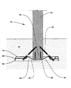
be
disposed of at specialized landfill sites.
[0003] Another conventional way to secure a post is to insert the post into
a
socket having a large heavy spike and driving the socket into the ground. The
anchor spikes are typically made of metal to withstand the forces needed to
drive
the spike socket into the ground. The socket spike or the post may become
tilted
during the process of setting the spike and inserting the post, resulting in a
tilted
1
CA 03121283 2021-05-27
WO 2020/124215 PCT/CA2019/051826
post. A metal spike is heavy to manufacture and transport. Moreover, a metal
spike socket may be vulnerable to corrosion while buried in the earth.
[0004] US patent 3,809,346 teaches a fence post having a rectangular base
plate which rests on the surface of the ground. A vertically extending socket
is
attached to the base plate to contain one end of the fence post. Drift pins
are
inserted into brackets fixed onto the socket and driven through slots in the
base
plate to enter the ground at an angle of about 45 degrees to the vertical to
lock the
fence post support to the ground. Fence posts are supported in the fence post
sockets to carry fencing in a conventional manner. The socket is metallic and
is
welded to the base plate. This anchor is not intended to be buried in the
ground.
The anchor relies upon the height and strength of the walls of the socket to
retain
the post in a vertical position, and the retention of the drift pins in the
ground to
secure the base plate to the ground.
[0005] German patent 3,820,698 teaches a foundation for signposts which
consists of lightweight plastic mouldings which can be joined to one another
with
bolts or fasteners to surround and support a signpost. Each of the mouldings
has a
baseplate and an outer wall which protrudes upward from the baseplate. An
inner
wall also protrudes from the baseplate (and surrounds the post). Support ribs
extend between the inner and outer walls and are fixed to the baseplate. The
mouldings are attached to the signpost at any desired height in the region of
its
insertion into the ground and achieve a tilting stability of the signpost. For
extra
strength the cup-like segments formed by the base plate, the support ribs and
the
inner and outer walls can be filled with concrete or other material. The post
2
CA 03121283 2021-05-27
WO 2020/124215 PCT/CA2019/051826
protrudes through the foundation, such that the foundation does not support
the
weight of the post and would not prevent the post from being directly
uprooted.
[0006] International application W02010000403 teaches a stabilizer and
adjusting device for ground anchorages. The stabilizer is intended for use on
an
already built already in the ground anchor, to improve stability and increase
the
force required to pull the anchor out of the ground. The stabilizer comprises
a
laterally extending baseplate and rods which protrude through the baseplate at
oblique angles and are anchorable in the ground, substantially increasing the
pull-
out forces and improving the stability against tilting. Figure 4 shows a
stabilizer
base plate with a number of radially extending clamping elements 15
(preferably
threaded spindles) arranged on the stabilizer base plate. This stabilizer does
not
support the base of the post, and such that it does not rely on the weight of
the
post itself for additional stability.
[0007] US patent No. 9,238,922 teaches a ground anchor for a flexible
delineator. The ground anchor includes a unitary plastic body having a
receptacle
shaped and configured for connection to a delineator post and a ground
engaging
anchor portion extending from the receptacle along a longitudinal axis. The
anchor
portion includes a plurality of tapered blades. Delineator assemblies using
the
ground anchor, and methods of installing the ground anchor, are also provided.
The patent teaches that the anchor which is embedded in the ground is
comprised
of a lightweight unitary plastic body or base, preferably constructed from
high
impact polystyrene or similar materials.
3
CA 03121283 2021-05-27
WO 2020/124215
PCT/CA2019/051826
SUMMARY OF THE INVENTION
[0008] An anchoring system for securing a post into the ground comprises an
anchor plate for insertion into a hole in the ground. The anchor plate defines
a
post receiver to receive a first end of the post and support the weight of the
post.
A ground supporting body extends laterally from the post receiver. A plurality
of
struts is attachable to the post and mountable to the anchoring plate at
positions
distal to the post receiver. The post receiver is a recess within the anchor
plate
having a base sized and positioned to receive the first end of the post. The
base
defines an opening to receive a fastening means for securing the post to the
post
receiver. The anchor plate defines a plurality of indentations at positions
distal to
the post receiver, each one of said indentations being adapted to seat one of
the
plurality of struts.
[0009] Each of the indentations comprises a back wall and a front wall. The
back wall presents a seating surface to orient a corresponding one of the
struts
toward the post at an angle between 30-70 degrees. Each of the indentations
defines an opening through its back wall to receive one of the plurality of
struts
therethrough.
[0010] Each of the struts has a first end for mounting within one of the
indentations in the anchor plate and a second first end for attachment to the
post.
Each of the struts is a hanger bolt having a thread at the first end to
receive a nut
4
CA 03121283 2021-05-27
WO 2020/124215 PCT/CA2019/051826
for mounting to the anchor plate, and a tapered screw thread at the second end
thereof for threaded attachment to the post.
[0011] A method of securing a post into the ground has the following steps.
A
first end of the post is seated on a post receiver of an anchoring plate and
fastened to the anchoring plate. The first ends of a plurality of struts are
seated
into a corresponding plurality of indentations in the anchor plate at
positions distal
to the post receiver. The second ends of the plurality of struts are attached
to the
post at positions adjacent to the first end of the post. The plurality of
struts is then
mounted to the anchor plate. Next, the first end of the post with the anchor
plate
fixed thereto is inserted into a hole in the ground. The ground is backfilled
onto
the anchor plate to bury the anchor plate while allowing the post to protrude
above
ground level. Finally, the ground is tamped around the post to pack the ground
onto the anchor plate.
BRIEF DESCRIPTION OF THE DRAWINGS
[0012] FIG.1 is a sectional view of a post and an anchoring system for
securing
post, shown installed in the ground
[0013] FIG.2 is a top plan view of an anchoring plate in accordance with
the
present invention.
[0014] FIG. 3 is a side view of the anchoring plate being fixed to the
post;
[0015] FIG.4 is a side view of the anchoring plate being tensioned.
[0016] FIG.5 is a perspective view of the post and anchoring system being
lowered into a hole dug in the ground.
CA 03121283 2021-05-27
WO 2020/124215 PCT/CA2019/051826
[0017] FIG.6 is a perspective view of the post and anchoring system in the
ground and being back filled.
[0018] FIG.7 is a perspective view of the post installed on site with
surrounding
fill being tamped.
DETAILED DESCRIPTION
[0019] Certain terminology is used in the following description for
convenience
only and is not limiting. The words "lower," "bottom," "upper," and "top"
designate
directions in the drawings to which reference is made. The words "inwardly,"
"outwardly," "upwardly" and "downwardly" refer to directions toward and away
from, respectively, the geometric center of the device, and designated parts
thereof, in accordance with the present disclosure. Unless specifically set
forth
herein, the terms "a," "an" and "the" are not limited to one element, but
instead
should be read as meaning at least one." The terminology includes the words
noted above, derivatives thereof and words of similar import.
[0020] The description of the present invention has been presented for
purposes of
illustration and description in order to best explain the principles of the
invention
and the practical application, and to enable others of ordinary skill in the
art to
understand the invention for various embodiments with various modifications as
are suited to the particular use contemplated.
[0021] The present invention is an anchoring system for securing a post into
the
ground. In FIG.1 the anchoring system 10 is shown in operation securing a post
12 in the ground 14. The post 12 is shown with a first end 16 buried
underground
6
CA 03121283 2021-05-27
WO 2020/124215 PCT/CA2019/051826
and the remainder extending above ground. The post 12 could be of any desired
height, however, for convenience only a portion of the post has been shown in
the
drawings. The anchoring system 10 comprises an anchor plate 18 plate for
insertion into a hole in the ground. The anchor plate 18 defines a post
receiver 20
to receive the first end 16 of the post 12 and to support the weight of the
post. The
anchor plate 18 extends beyond the footprint of the post on all sides defining
a
laterally extending ground supporting body 22 surrounding the post receiver
20. A
plurality of struts 42 are attachable to the post 12 and mountable to the
anchor
plate 18 at positions distal to the post receiver. Preferably, at positions on
the
ground supporting body 22 equidistant from the post and diagonally opposed to
one another. Since FIG. 1 is a sectional view, only two of the struts are
visible,
however their positioning equidistant from the post and diagonally opposed to
one
another can be seen.
[0022] The contours of the anchor plate 18 are clearly shown in FIG.2 The post
receiver 20 is a recess in the top of the surface of the plate which is sized
and
positioned to receive the first end of the post. The base 30 of the recess is
a
smooth flat surface to mate well with the squared off first end 16 of the post
and to
provide a level surface upon which to support the weight of the post. The post
receiver 20 may be constructed to accommodate a variety of cross-sectional
post
sizes and shapes. By way of example the post receiver 20 is shown as a recess
having three nested borders 24, 26, 28. The innermost border 24 defines a
space
which would accommodate a post having a small square cross section. The base
30 would support the first end of the post as mentioned above. The middle
border
7
CA 03121283 2021-05-27
WO 2020/124215 PCT/CA2019/051826
26 defines a somewhat larger space to accommodate a larger post. It should
also
be noted that a first raised step 32 is formed between the innermost border 24
and
the middle border 26. This first raised step 32 provides a smooth, flat and
level
surface to support the perimeter of the first end 16 of the post. The outer
border
28 defines a larger square cross section to accommodate a larger post. A
second
raised step 34 is formed between the outer border 28 and the middle border 26.
The second raised step 34 provides a smooth flat surface to support the
perimeter
of the first end of a larger post. It should be understood that the post
receiver 20 is
not in the nature of a deep socket or sleeve. The post receiver does not
engage
the sides of the post and does not function in maintaining the post in a
vertical
position. Instead it serves as a footprint for the first end 16 of the post 12
on the
anchor plate 18.
[0023] The base 30 of the post receiver 20 defines an opening 36 to receive a
fastening means 38 (shown in FIG. 1) for securing the post to the post
receiver 22
of the anchor plate 18. In the embodiment illustrated, there may be provided
more
than one opening 36 and more than one fastening means 38 which can be used to
fasten the post 12 to the anchor plate. The post 12 can be fastened to the
anchor
plate 18 by fastening means 38 extending through the opening(s) 36 the anchor
plate in the base 30 of the anchor plate 18 and embedded into the base of the
first
end 16 of the post 12.
[0024] The anchor plate 18 defines a plurality of indentations 40 at positions
which
are distal to the post receiver 20. The indentations are located on the ground
supporting body 22 distal to the post receiver 20. As illustrated in FIG. 2,
in the
8
CA 03121283 2021-05-27
WO 2020/124215 PCT/CA2019/051826
preferred embodiment the indentations 40 are positioned equidistant from the
post
receiver and diagonally opposed to one another. Four indentations 40 are shown
for illustrative purposes, but it should be understood that the plate 18 could
be
constructed with three or more indentations 40 arrayed at positions distal to
the
post receiver 20. Each one of the indentations 40 is adapted to seat one of a
corresponding plurality of struts 42 which are attachable to the post 12 and
mountable on the anchoring plate 18. As shown, each indentation 40 has a back
wall 44 (being the wall at the greater distance from the post receiver 20) and
a
front wall 45. The back wall 44 and the front wall 45 are sloped inwardly
toward
one another such that the indentations 40 have substantially V-shaped bottoms.
[0025] Each back wall 44 faces the post receiver 20 and is sloped at an angle
between 30-70 degrees. Each back wall 44 presents a seating surface which
orients the strut 42 toward the post 12 at an angle between 30-70 degrees. The
size of the seating surface should be just large enough to seat the strut 42.
The
orientation of the struts 42 relative to the plane of the anchor plate 18 and
the
plane of the post 12 provides lateral stability to resist lateral tilting
forces as well as
vertical uprooting forces. An angle of 45 degrees will provide optimal load
transfer
between the anchor plate 18 and the post 12, spreading the load outward from
the
center of the anchor plate. In the extreme, an angle approaching either zero
or 90
degrees would provide no load transfer. The struts 42 may act in tension or in
compression to resist whatever directional force is applied to the post 12
once the
anchoring device 10 is fully assembled and attached to the post. Each of the
struts 42 comprises a first end 48 adapted for mounting within one of the
9
CA 03121283 2021-05-27
WO 2020/124215 PCT/CA2019/051826
indentations 40 in the anchor plate 18 and a second end 50 adapted for
attachment to the post 12 adjacent the first end 16 thereof.
[0026] In the preferred embodiment of the invention best seen in FIG 1 and
FIG. 3,
each of the struts 42 may be constructed as a hanger bolt having a threaded
first
end 48 to receive a nut 52 for mounting to the anchor plate 18, and a tapered
screw thread at the second end 50 for threaded engagement to the post 16.
[0027] The indentations 40 in the anchor plate 18 preferably each define an
opening 46 to receive one of the struts 42 therethrough. As shown in FIG. 2
each
of the openings 46 is located on the back wall 44 of the indentation 40. When
the
struts 42 are mounted to the anchor plate 18 within the indentations 40, the
sloped
shape of the back wall 44 orients each strut 42 toward the post 12 at an angle
between 30-70 degrees, and as discussed above, optimally at a 45-degree angle
for the greatest load transfer between the post and the anchor plate. The back
wall
44 should be just large enough to fit the first end 48 of the strut and still
be able to
tighten the nut 52 with an open-ended wrench. The size of the opening 46 is
also
important. The opening 46 should be just large enough to fit the first end 48
of the
strut 42 in order to prevent the strut from shifting in an oversized hole when
forces
are applied. Minimizing the flat surface size and positioning any bends in the
anchor plate 18 closer to the opening 46 (the location of contact between a
bolt/nut received through the opening) reduces the ability of the material of
the
anchor plate 18 to flex around the connection due to applied forces. Flexion
of the
anchor plate 18 should be avoided.
CA 03121283 2021-05-27
WO 2020/124215 PCT/CA2019/051826
[0028] In an alternative embodiment not shown in the drawings, each of the
struts
42 may comprise a first end 48 adapted for mounting within one of the
indentations 40 in the anchor plate 18. Instead of having the threaded first
end
pass through an opening in the anchor plate and receive a nut for mounting to
the
anchor plate, the first end 48 might be provided with a foot angled to seat
against
the back wall 44 of the indentation without passing through an opening in the
back
wall. The second end of the strut would still be fixed firmly, and preferably
embedded in the post. In this embodiment, the strut would provide compressive
load bearing support to resist lateral forces applied to the post. The
fastener(s)
which secure the bottom of the post to the base of the post receiver of the
anchoring plate would provide load bearing strength in tension to prevent
uprooting of the post. With the anchor plate fastened to the post, the struts
would
be effectively mounted to the anchor plate by retention of the first end of
each strut
against the back wall within one of the indentations in the anchor plate.
[0029] In a second alternative embodiment, the anchor plate could be contoured
with sockets or key hole notches to lock onto specially contoured rods to
serve as
struts. Each of the rods would be locked to the anchor plate at their first
ends and
then screwed into the post at their second ends.
[0030] The anchor plate 18 is constructed to be relatively thin but rigid and
lightweight. Preferred materials from which to construct the anchor plate 18
could
include steel, aluminum or other metals or alloys which have similar strength
characteristics to steel. The material must not be brittle and should be very
resistant to cracking or tearing. The anchor plate 18 can be constructed with
11
CA 03121283 2021-05-27
WO 2020/124215 PCT/CA2019/051826
strengthening contours 60, such as dimples, bends, ribs or webs to add
strength to
the anchor plate to resist flexion. A further advantage of strengthening
contours
60 is that once the anchor plate is buried, the ground will be captured in any
dimples or hollows formed in the plate improving retention of the plate within
the
surrounding ground.
[0031] The anchor plate 18 is downwardly angled (as indicated by reference
numeral 56) adjacent its perimeter to form at the perimeter of the anchor
plate 18
a biting edge 54 directed downward for contact with the ground beneath the
anchor plate.
[0032] In order to secure a post into the ground according to the present
invention
a method having the following steps method may be followed. As shown in FIG.
3,
the first step is seating a first end 16 of a post 12 on a post receiver 20 of
an
anchoring plate 18. Next, the first end 16 of the post is fastened to the
anchor
plate 18. A plurality of struts 42 are provided, each strut having a first end
and a
second end. The first ends 48 of each of the plurality of struts 42 is seated
into
one of a corresponding plurality of indentations 40 defined in the anchor
plate 18
at positions distal to the post receiver 20. The second ends 50 of each of the
plurality of struts is attached to the post 12 at positions adjacent to the
first end 16
thereof. Next the first ends 48 of the plurality of struts 42 are mounted to
the
anchor plate 18.
[0033] In a preferred embodiment the struts are received within openings 46
through the anchor plate 18. Each opening 46 is located in a back wall 44 of
one
of the indentations 40 in the anchor plate 18. The first ends 48 of the
plurality of
12
CA 03121283 2021-05-27
WO 2020/124215 PCT/CA2019/051826
struts 42 are threaded to receive a nut 52 for mounting to the anchor plate.
Each
of the plurality of struts 42 has a tapered screw thread at a second 50 end
thereof.
Each of the plurality of struts 42 is turned to embed the tapered screw thread
into
the post adjacent the first end 16 thereof. As shown in FIG. 4, once the
second
end 50 of each of the struts 42 is embedded within the post 12, the first ends
48 of
each of the struts is mounted to the anchor plate. This mounting step is
accomplished by tightening the nuts 52 onto the struts 42 adjacent their first
ends
48.
[0034] As shown in FIG. 5, the next step is inserting the first end 16 of the
post 12,
having the anchor plate 18 fixed thereto, into a hole in the ground.
Preferably the
hole will be flat bottomed and level. The depth of the hole will be selected
by the
person who installs the post. The desired depth for any given installation
would
vary with the height of the pole, the make-up of the ground, soil type, rock
content,
moisture levels, etc. As shown in FIG. 6, the anchor plate 18 is positioned in
the
bottom of the hole with the biting edge 54 of the perimeter of the anchor
plate 18
directed downward for biting contact with the ground below the anchor plate 18
and then the ground is backfilled onto the anchor plate 18. The ground
supporting
body 22 receives and supports the ground. Likewise, the contours 60 retain
ground. The anchor plate 18 is completely buried inside the hole while
allowing
the post 12 to protrude above ground level.
[0035] Finally, as shown in FIG. 7, once the ground has been replaced to
completely fill the hole, the ground is tamped using a tamper 58 to pack the
ground onto the ground supporting body 22 of the anchor plate 18, into the
13
CA 03121283 2021-05-27
WO 2020/124215 PCT/CA2019/051826
contours 60, and to permit the biting edge 54 of the perimeter of the anchor
plate
to form a biting contact with the ground below the anchor plate.
[0036] In principle the anchoring system 10 according to the present invention
relies upon the weight of the ground on top of the anchor plate 18 to secure
the
post 12 into the ground 14. The post is fixed to the anchor plate by the
combined
downward weight of the post 12 resting on the post receiver of the anchor
plate
18, the fastener 38 secured through the fastener opening 36 in the base 30 of
the
anchor plate 18 and into the base of the post, and the presence of the struts
42
attached to the post 12 and mounted to the anchor plate18. The struts 42 are
held
in compression between the anchor plate 18 and the post 12. The presence and
the angled orientation of the struts 42 provides lateral stability to resist a
lateral
load applied to the post above ground level. Thus, the post 12 will be
stabilized
against tilting or tipping. The fastening of the anchor plate 18 to the post
12
provides tension to resist any upward force preventing the anchor from being
uprooted. There are also vertical forces to resist. Frost in the up direction
and the
weight of the fence in the down direction. The struts also distribute these
forces
farther out from the middle of the plate. Without the struts, these forces
would be
applied within the dimensions of the post (4x4 or 5x5 or 6x6). Without the
struts to
spread out the load, the plate material would need to be thicker to achieve
the
same vertical resistance without bending or deforming.
[0037] The anchoring system 10 of the present invention has been designed so
that the anchor plate 18, the fasteners 38, and the struts 42 are all
detachable
from the post 12. If the post becomes damaged and requires replacement, it is
a
14
CA 03121283 2021-05-27
WO 2020/124215 PCT/CA2019/051826
simple matter to unearth the anchor plate and remove the fastener and struts
to
disengage the post from the anchor plate. The old post can be removed and a
new post can be attached to the anchor plate using the same fastener and
struts
and the anchor plate can be reburied. There is no need to replace or dispose
of
the anchor plate.
[0038] The anchor plate is much lighter and easier to manufacture than
conventional spike sockets. The anchor plate is fabricated as a single piece
construction with no crevices or cracks that would make painting difficult.
Anchor
plates can be stacked on one another for storage and shipping. The anchor
plates can be manufactured from corrosion resistant materials or treated with
corrosion resistant methods such as painting or galvanizing.