Note: Descriptions are shown in the official language in which they were submitted.
CA 03121416 2021-05-28
- I -
Elevator rail
The present invention relates to an elevator rail having more than one guide
contour. The
invention also relates to a guide system and an elevator system which have
such elevator
rails.
In an elevator system, a moving body, i.e., an elevator car or a
counterweight, is typically
displaced vertically along a travel path between different floors or levels
within a
structure. Typically, each moving body is guided by two elevator rails which
are often
attached independently of one another to different shaft walls. At least in
tall buildings,
an elevator type is usually used in which the elevator car is held by rope or
belt-like
suspension elements and displaced within an elevator shaft by moving the
suspension
elements by means of a drive machine. In order to at least partially
compensate for the
load of the elevator car to be moved by the drive machine, a counterweight is
usually
attached to an opposite end of the suspension elements. This counterweight has
at least
the same mass as the elevator car. As a rule, the mass of the counterweight
exceeds that
of the elevator car by half of the payload to be transported permissibly by
the elevator car.
Depending on the type of elevator, a plurality of counterweights and/or a
plurality of
elevator cars can also be provided in an elevator system.
DE20105144 Ul shows an elevator system which guides two counterweights inside
two
hollow elevator rails.
EP3103753 Al shows an elevator rail system which is formed from sheet metal
and, as a
functional combination in the same component, contains guide contours for the
counterweight and the car.
Among other things, there can be a need for a guide system, an elevator rail
and/or an
elevator system in which a base surface and/or a space requirement for the
elevator
system is low and in which the total costs for the elevator system can
nevertheless be kept
low. Furthermore, there can be a need for a counterweight and an elevator
system
equipped with said counterweight, in which a number of elevator components
used to
hold and guide the counterweight can be kept small and thus an installation
effort and
CA 03121416 2021-05-28
- 2 -
costs can be reduced. Furthermore, there can be a need for an elevator system
that places
low demands on the precision of the on-site building interfaces, in particular
the flatness
of shaft walls.
At least one of the demands mentioned can be met with the subject matter
according to
any of the independent claims. Advantageous embodiments are defined in the
dependent
claims and in the following description.
According to a first aspect of the invention, the elevator rail according to
the invention is
used to guide the moving bodies of an elevator system. The moving bodies serve
as a car
for the transport of people or goods or as a counterweight. The elevator rail
has more than
one guide contour. The guide contour is suitable for interacting with a guide
shoe such
that in a first horizontal direction, a relative horizontal movement between
the guide
contour and the guide shoe is delimited at least on one side, and that in a
second
horizontal direction, perpendicular to the first horizontal direction, a
relative horizontal
movement between the guide contour and guide shoe is delimited on both sides.
The
elevator rail has a hollow cross section bordered in a closed manner. The
elevator rail has
at least three guide contours, wherein the guide contours are formed on the
outer surface
of the elevator rail.
According to a second aspect of the invention, a guide system according to the
invention
comprises a first and a second of the above-described elevator rails.
According to a third aspect of the invention, an elevator system with the
above-described
guide system has two counterweights and a car, wherein each of the elevator
rails guides
one counterweight by itself.
Possible features and advantages of embodiments of the invention can be
considered,
among other things and without limiting the invention, to be dependent upon
the concepts
and findings described below.
The guide contour of an elevator rail is the interaction surface between the
elevator rail
and a guide shoe. In a conventional elevator rail, for example, a T89, the
guide contour
corresponds to the three smoothed surfaces on the elevator rail head. These
three surfaces
CA 03121416 2021-05-28
-j -
are at right angles to one another and each serves as a running surface for a
contact
surface or a roller of a guide shoe. In this case, the end face of the
elevator rail can delimit
the movement of the guide shoe perpendicular to the end face of the guide shoe
only on
one side, whereas the two side surfaces delimit the movement of the guide shoe
perpendicular to the side surfaces on both sides.
A guide contour is usually designed in the form of a tongue. For this purpose,
the tongue
is usually designed to be rectangular; it protrudes from a load-bearing
element, in
particular a rail foot, such that it can be encompassed by a guide shoe.
Completely
different guide contours are also known, in particular round and triangular
guide
contours.
As already indicated above, conventional elevator rails each have only one
guide contour.
Elevator systems using such elevator rails therefore normally have two
elevator rails per
moving body because the design should not only delimit the movement in all
horizontal
directions but also a rotation about the vertical axis. For a typical elevator
with a
counterweight, four elevator rails are therefore necessary.
The advantage of the proposed elevator system is that an elevator rail has at
least three
guide contours. As a result, the number of elevator rails required can be kept
small. This
not only saves material of an elevator rail as such; the saving effect also
means that fewer
elevator rail holders are installed because fewer elevator rails are to be
held. The
installation effort is also reduced. Advantageously, only two elevator rails
are required to
guide three moving bodies, i.e., a car and two counterweights.
An elevator rail with a cross section bordered in a closed manner has an empty
region in
the interior, while the material is concentrated in an edge region. Individual
holes in the
elevator rail, for example, for realizing screw connections, do not contradict
the property
of the cross section bordered in a closed manner. A slot over the entire
length of the
elevator rail would no longer be compatible with the cross section bordered in
a closed
manner. An elevator rail bordered in a closed manner can also be called a
hollow elevator
rail. In this case, the interior of the elevator rail does not necessarily
have to be empty or
only filled with air. The elevator rail can also be filled. Foamed polymers,
sand or
concrete are particularly suitable for this purpose.
µCA 03121416 2021-05-28
- 4 -
The design of the elevator rail with a cross section bordered in a closed
manner is
advantageous because, with the same material input, it is significantly
sturdier than an
open cross section. There are methods for producing such an elevator rail, for
example,
extrusion molding or the assembly of a plurality of parts.
It would also be possible to guide a counterweight inside a hollow elevator
rail. However,
for this purpose, the counterweight would have to be extremely tall, or the
elevator rail
would have to have a very large internal cross section. It is therefore
advantageous if the
guide contour is realized on the outer surface of the hollow elevator rail.
In the following, further embodiments of the invention will be described.
According to one embodiment of the elevator rail, at least one of the guide
contours is
designed as a groove which is used to guide a guide shoe.
This feature can be regarded as an independent invention. Independently of
claim 1, an
elevator rail for guiding moving bodies of an elevator is thus disclosed,
wherein the
moving bodies are used to transport people or goods or as a counterweight. For
this
purpose, the elevator rail has at least one guide contour which is designed as
a groove and
used to guide a guide shoe.
The groove is characterized in that the outer surface of the elevator rail has
an indentation
at the location of the guide contour, the interior of said indentation being
used to
accommodate a guide shoe.
It is advantageous to design a guide contour as a groove into which a guide
shoe
protrudes. In this case, the groove can be designed to be rectangular, so that
a guide shoe
can be guided inside the groove. The rectangular groove can also delimit the
movement
of the guide shoe perpendicular to the central surface of the guide shoe on
only one side,
while the two side surfaces delimit the movement of the guide shoe
perpendicular to the
side surfaces on both sides.
The advantage of a groove, in particular when it concerns the car guide, is
that a large
CA 03121416 2021-05-28
- 5 -
part of the guide shoe runs in the groove, leaving more space for the car next
to the
elevator rail. It can be assumed that the elevator rail must have a specific
base surface in
order to be able to absorb the necessary forces. The car wall and, behind it,
the usable
space in the car could run directly adjacent thereto. If the guide contour
were to extend
out of the elevator rail in the direction of the car, it would result in a
decrease in size of
the car because the guide contour would otherwise extend into the car.
However, with
such a guide contour, the guide shoe also extends around the guide contour,
further
reducing the region usable for the car. However, if the guide contour extends
into the
elevator rail, i.e., away from the car, space is freed up that can be taken up
by the guide
shoe, and the entire space is available for the car.
Advantageously, the groove also has larger contact surfaces, which has a
positive effect
on abrasion, in particular from sliding shoes. In particular, the bottom or
the central part
of the groove can be much wider than is usual for the end face of a classic
elevator rail
such as the T89.
According to one embodiment of the elevator rail, the guide contour is
designed as a
groove and to be essentially rectangular.
The rectangular shape has the advantage that the guiding behavior is
comparable to that
of a classic elevator rail. Shapes other than an essentially rectangular shape
could cause
other forces to occur. If the guide contour were triangular, for example,
pressing a
triangular guide shoe into the triangular groove would greatly increase the
normal forces
and thus the frictional forces.
According to one embodiment of the elevator rail, the elevator rail is
essentially
triangular, in particular it is essentially right-angled triangular.
The triangular shape allows for a better utilization of the narrow space in
the elevator
system. As a result, more space can ultimately be made available in the car
for the
transport of people and goods.
The advantage of a right-angled triangular arrangement is that the two legs,
which are at
right angles to one another, can be aligned according to the axes of the
elevator. A first of
CA 03121416 2021-05-28
- 6 -
the two legs can thus be aligned parallel to a shaft wall, for example, the
front wall. A
connection from the shaft wall to the first leg can now be realized using a
simple bracket.
The second of the two legs is thus aligned parallel to a car wall. It is
therefore not
necessary to create an oblique-angled connection in order to form a guide
contour on the
second leg for guiding the car.
According to one embodiment of the elevator rail, the guide contour is
designed as the or
a groove, and at least two further guide contours are designed as tongues,
wherein the two
guide contours designed as tongues lie at corner points of the essentially
triangular
elevator rail that are furthest apart from one another.
The longest of the three sides of the essentially triangular elevator rail is
advantageously
used such that one guide contour for guiding the counterweight is attached to
each of the
two ends of said longest side. As a result, the distance is relatively large
and the
counterweight is also sufficiently guided around its vertical axis of
rotation. The closer
the two guide contours for guiding the counterweight are to one another, the
worse the
counterweight is held in the required alignment around the vertical axis. This
reliably
prevents the car or the shaft walls from being touched by the more distal ends
of the
counterweight.
Since these two contours are designed as tongues at the ends of the longest
edge, the two
points of force transmission of the guide forces at the tongues are
advantageously
separated even further from one another. As a result, the guiding of the
counterweight
around the vertical axis becomes even more stable.
The guide contour designed as a groove lies advantageously on a leg of the
essentially
right-angled triangular cross section and is used to guide the car or the car
guide shoe.
According to one embodiment of the elevator rail, a braking contour is
configured which
is separate from the guide contours and which serves as a braking surface for
a safety
brake.
The braking contour is characterized in that a safety device can act on the
braking
contour, thus bringing in particular the car safely to a halt. The braking
contour is
= CA 03121416 2021-05-28
- 7 -
advantageously designed as a tongue, so that a safety brake can be used which,
according
to the conventional principle, compresses the tongue, i.e., the brake rod, in
order to
generate the corresponding frictional forces. The pressure forces that are
introduced into
the elevator rail as a result of the action of the brake linings merely press
the braking
contour closer together. However, the elevator rail will essentially not be
deformed in the
process.
Nevertheless, the braking contour can alternatively also be designed as a
braking contour
groove, in which case the safety brake is braced against the outside in the
braking contour
ci groove in order to generate the corresponding frictional forces. In
this case, the elevator
rail is designed to be so sturdy that the profile can withstand the pressure
forces.
A further advantage of the braking contour is that the safety devices do not
act on the
elevator rails where the guide shoes are guided. Any small damage to the
braking contour
due to previous braking actions has no negative effect on the riding comfort.
According to one embodiment of the elevator rail, the elevator rail has a
bracket fastening
contour which allows for a bracket to be attached in a vertically movable
manner.
Advantageously, the bracket is attached to the bracket fastening contour such
that it can
be moved upwards and/or downwards in the bracket fastening contour. This
allows for
the problem of building subsidence to be taken into account. If the building
is still
subsiding after the elevator has been installed, the bracket that aligns the
elevator rail can
be moved downwards along the bracket fastening contour without applying a
moment to
the elevator rail or the bracket being bent.
According to onc embodiment of the elevator rail, the elevator rail comprises
at least one
shaped sheet metal.
The use of sheet metal has the advantage that the elevator rail can be
manufactured
inexpensively and at a high quality. In comparison to a solid rail, there is
also a weight
saving which simplifies the transport and installation of the elevator rails.
The elevator rails are manufactured using generally known techniques for
manufacturing
CA 03121416 2021-05-28
- 8 -
rolled sheet metal profiles. A cross section bordered in a closed manner is
achieved by
closing the elevator rail. In particular, the joint can be welded to close the
cross section,
or it is folded over and spot-welded, crimped or closed using a similar
method.
According to one embodiment of the guide system, the guide system has a
plurality of
brackets which are each fastened to an elevator rail, and the brackets connect
an elevator
rail directly or indirectly to a shaft wall.
The advantage of the brackets is that they can be designed in a simple manner.
The space
to can be used optimally.
According to one embodiment of the guide system, the brackets are connected to
the
same one shaft wall, wherein the shaft wall is in particular the front wall in
which the
floor openings are integrated.
This has the advantage that only one of the four shaft walls meets the
relatively precise
geometry and construction requirements for elevator construction. The
structural
precision of the other shaft walls can be lower. There is also the advantage
that it is
sufficient that the material of the front wall with the floor openings meets
the
requirements of elevator construction with regard to force transmission in
order to attach
an elevator to it. All other shaft walls can be made from materials that are
unsuitable for
fastening an elevator system, in particular also from significantly weaker
materials.
According to one embodiment of the guide system, the two elevator rails are
connected at
least at one height in the shaft via a clamp bracket, wherein one clamp
bracket has a
bracket of the first elevator rail, a bracket of the second elevator rail and
a connecting part
that connects the two brackets.
For this purpose, the two brackets and the connecting part can be firmly and
inseparably
connected to one another, i.e., formed from one component, or they can be
individual
components that can be joined, for example, via releasable screw connections.
The advantage of such a clamp bracket is that the distance between the two
elevator rails
is predetermined by the connecting part. The track width for the car, i.e.,
the distance
= CA 03121416 2021-05-28
- 9 -
between the two guide contours used to guide the car, is thus fixed. A
separate setting of
the distance is therefore largely unnecessary.
In addition, only one clamp bracket per fastening level needs to be aligned
and fastened
during installation. Without the connecting part, two individual brackets
would have to be
aligned and fastened separately. With the use of the clamp bracket, the
installation effort
can thus be almost halved.
According to one embodiment of the guide system, the clamp bracket is attached
to a
single shaft wall, in particular to the front wall.
The clamp bracket can be connected to the shaft wall, in particular the front
wall, via the
connecting part. The brackets are then indirectly connected to the shaft wall.
There are
the same advantages as in the above embodiment with the brackets connected to
the same
one shaft wall.
According to one embodiment of the elevator system, both the two elevator
rails each
guide an associated counterweight via two guide contours and the two elevator
rails
jointly guide the car via a third guide contour.
This has the advantage that it is sufficient to mount only two instead of four
or even six
elevator rails. This is advantageous because by using two counterweights, the
base
surface of the shaft can be optimally utilized.
Further advantages, features and details of the invention will become apparent
from the
following description of embodiments and from the drawings, in which identical
or
functionally identical elements are denoted with identical reference signs.
The drawings
are merely schematic and not to scale.
In the drawings:
Fig. 1 shows a cross section of an elevator system with an embodiment of the
elevator
rail.
Fig. 2 is a detailed view of a cross section of an alternative elevator rail
in an elevator
system.
CA 03121416 2021-05-28
- 10 -
Fig. 3 shows a cross section of a further alternative embodiment of the
elevator rail in
the elevator system.
Fig, 4 is a detailed view of a cross section of the further alternative
elevator rail
according to Fig. 3 in isolation.
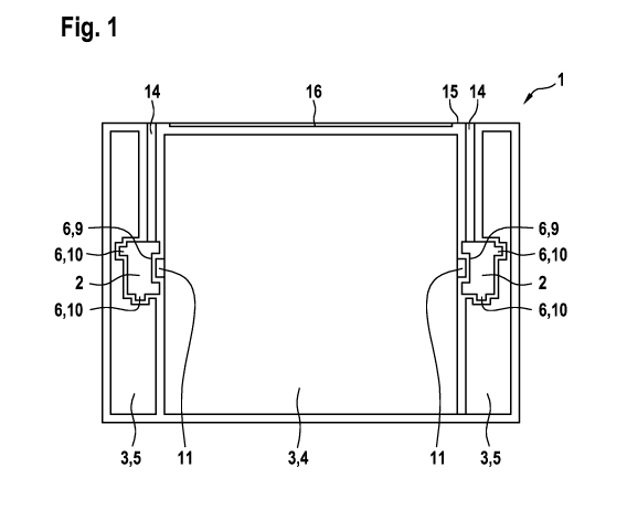
Fig. 1 shows an elevator shaft of an elevator system I. The elevator system 1
comprises
three moving bodies 3, i.e., a car 4 and two counterweights 5, and two
elevator rails 2.
Each of the elevator rails 2 has at least three guide contours 6. The car 4 is
guided by a
respective guide contour 6, in this case a groove 9, of the two elevator rails
2. The car 4
has guide shoes 11 which engage in the groove 9 of the elevator rail 2. Each
single
elevator rail 2 is held in the elevator shaft in that it is connected to the
front wall 15 of the
elevator shaft via brackets 14. The front wall 15 is characterized in that the
landing doors
are located in this wall. As a result, the door sills 16 are also attached to
this front wall 15.
One counterweight 5 each is guided on a respective elevator rail 2. In order
to ensure that
the counterweight 5 moves neither horizontally nor rotates about the vertical
axis, each
individual counterweight 5 is guided on two guide contours 6 of the elevator
rail 2. The
further these two guide contours 6 are spaced apart from one another, the more
effectively
a twisting of the counterweight 5 can be prevented. In this example, the two
guide
contours 6 which each hold a counterweight 5 are designed as tongues 10. As a
result, a
distance between the two guide contours 6 of a counterweight is additionally
increased.
The elevator rail 2 itself is formed, for example, from sheet metal. The
counterweights 5
are optimally shaped such that they optimally fill the remaining space next to
the car.
Fig. 2 is a more detailed view of an elevator rail 2 which could be used in an
elevator
system 1 similar to that of Fig. I.
The elevator rail 2 or at least parts of the elevator rail consist of sheet
metal 13 which is
preferably brought into the shape of the elevator rail 2 or the parts thereof
by a rolling
process. In Fig. 2, the elevator rail 2 is designed to be essentially
rectangular. In this view,
the elevator rail 2 on the upper flank of the rectangle is designed such that
it can be
connected to the bracket 14. The contour shown in Fig. 2 allows the bracket 14
to be
CA 03121416 2021-05-28
- 1 1 -
moved along its longitudinal direction relative to the elevator rail 2. If the
building still
subsides in the first few months after construction, the brackets 14 can slide
along the
elevator rail 2 without the elevator rail 2 being damaged or deformed in the
process.
In this view, the elevator rail 2 on the right-hand flank of the rectangle is
designed such
that it serves as a guide for the car 4. The guide contour 6 is essentially
designed as a
rectangular groove 9a. The two sliding linings 12 of the guide shoe I I a are
guided in the
corners of the groove 9a. In addition to the groove 9a, a braking contour 17
is also
arranged inside the guide contour 6. In this case, the term "groove" is
supposed to refer to
the U-shaped groove 9a which actually has a continuous bottom and is
supplemented by
the braking contour 17 which protrudes from said continuous bottom. Since the
safety
brake 19 is pressed against the braking contour 17 during safety braking, the
surface of
the braking contour 17 can be damaged in the process. The sliding linings 12
do not touch
the braking contour 17 when sliding. Therefore, the damage that occurs to the
braking
contour 17 during safety braking does not have any influence on the quality of
the ride.
In this view, the elevator rail 2 on the left and lower flank of the rectangle
is designed
such that it forms one guide contour 6 each. These two guide contours 6 are
used to guide
a counterweight 5. In this case, the guide contour on the left flank is
designed as a groove
9b. Since this groove 9b has an undercut, the groove 9b can guide the guide
shoe I lb not
only in a second horizontal direction 8 on both sides, but also in the first
horizontal
direction 7. This has the advantage that the counterweight 5 is thus guided
more securely.
However, the introduction of the guide shoe 1 I b into the elevator rail
requires specific
measures. For this purpose, a guide shoe I I b is designed, for example, such
that it only
reaches its full width in the groove 9b. For example, a two-part guide shoe
1lb can be
inserted in individual parts and is then assembled in the groove 9b, so that
its shape
adapts to the shape of the rail. Alternatively, the guide shoe lib can be
designed such that
it has a flattened shape that fits through the narrow passage of the groove 9b
and by
twisting it, the guide shoe 1 lb reaches the full width of the rail. However,
alternatively, it
is also possible to design the elevator rail 2 at specific installation and
removal points for
the counterweights 5 such that the guide shoe llb can be extended and
retracted at such a
point.
The lower flank of the rectangle contains the second guide contour 6 which
guides the
= CA, 03121416 2021-05-28
- 12 -
counterweight 5 on this side of the car 4. In this example, said guide contour
is designed
as a tongue 10c. The guide shoe llc is designed as a sliding guide shoe.
In this view, the elevator rail 2 on the upper flank of the rectangle is
designed such that it
forms a bracket fastening contour 20. The bracket fastening contour 20 shown
in Fig. 2
allows the bracket 14 to jam in this bracket fastening contour 20. By
optimally selecting
the clamping force, a movement within the bracket fastening contour 20 is
possible if this
were to become necessary due to a subsiding of the building.
Fig. 3 shows a further possible embodiment of an elevator system 1 and a guide
system.
In this case, the elevator rail 2 is shown as being essentially triangular.
The elevator rail is
connected to the front wall 15 of the building via brackets 14. In this case,
it is a clamp
bracket 22 in which the two brackets 14 are connected along the front wall 15
to a
connecting part 21.
The counterweight 5, which is held by this one elevator rail 2, is guided via
two tongues
10. In order to keep the friction low, sliding linings 12 are attached to the
counterweight
5.
The car 4 is guided via one guide shoe 11 each. The guide shoe can be designed
as a
sliding guide shoe or as a roller guide shoe. When designed as a roller guide
shoe, the
rollers can be arranged such that one roller assumes the function of the one-
sided stop at
the bottom of the groove 9, and a second roller assumes the function of the
two-sided stop
at the side surfaces of the groove 9. As a result, the roller that realizes
the two-sided stop
rotates in one or the other direction, depending on where a load is located in
the car 4.
Even during a ride, a movement of the load in the car 4 can lead to the roller
losing
contact with one side surface and touching the other side surface, thereby
changing the
direction of rotation. However, three or more rollers can also be used, so
that a separate
roller is available for both side surfaces of the groove 9 and at least one
roller is available
for rolling on the bottom of the groove 9.
The car 4 has safety brakes 19. The safety brakes 19 are optimally attached
next to the car
4. This embodiment is also advantageous because the car 4 is not braked on a
surface
used for guiding; instead, a braking contour 17 is used exclusively for the
braking by the
= CA 03121416 2021-05-28
- 13 -
safety brake 19.
Fig. 4 is a detailed view of the cross section of an elevator rail 2 as used
in the
embodiment shown in Fig. 3. The elevator rail 2 is advantageously rolled from
sheet
metal and joint-welded at a suitable point. The guide contour 6 for the car is
located on
the left-hand side. It is designed as a groove 9a. A guide shoe attached to
the car can
engage in this groove 9a. In this case, a one-sided delimitation of the
movement is
ensured in the first horizontal direction 7a. The guide shoe of the car 4 can
only be moved
to the right in the first horizontal direction 7a until it bears against the
bottom of the
groove 9a. In the second horizontal direction 8a. a two-sided delimitation of
the
movement is ensured. The guide shoe of the car can only be moved in the second
horizontal direction 8a until it bears against the side surfaces of the groove
9a. Of course,
there can be some play but the movement is nevertheless delimited.
One of the two guide contours 6 of the counterweight is located at the bottom
of Fig. 4.
This guide contour 6 is designed as a tongue 10b. A guide shoe attached to the
counterweight can encompass this tongue 10b. In this case, a one-sided
delimitation of
the movement is ensured in a first horizontal direction 7b. The guide shoe of
the car can
only be moved in the first horizontal direction 7b until the tongue 10b bears
against the
bottom of the guide shoe. In a second horizontal direction 8b, a two-sided
delimitation of
the movement is ensured. The guide shoe of the car can only be moved in the
second
horizontal direction 8b until it bears against the side surfaces of the tongue
lob. Of
course. there can be some play, but the movement is nevertheless delimited.
The tongue 10c for the second guide shoe of the counterweight is located at
the top right
of the figure. As for 10b, it is also a tongue. With regard to the first
horizontal direction
7c and the second horizontal direction 8c, the same applies as for 7b and 7c.
The braking contour 17 is located at the top left. In this case, it is aligned
parallel to the
side wall of the car, so that the safety brake can be better accommodated in
the tight
spaces between the car and the bracket 14.
The bracket 14 is fastened to the elevator rail 2 between the braking contour
17 and the
tongue 10c. In this case, the bracket 14 is fastened to the elevator rail 2 by
means of a
CA 03121416 2021-05-28
- 14 -
screw connection 23.
Finally, it should be noted that terms such as "comprising," "having," etc. do
not preclude
other elements or steps and terms such as "a- or "an" do not preclude a
plurality.
Furthermore, it should be noted that features or steps that have been
described with
reference to one of the above embodiments can also be used in combination with
other
features or steps of other embodiments described above. Reference signs in the
claims
should not be considered to be limiting.