Note: Descriptions are shown in the official language in which they were submitted.
CA 03121426 2021-05-28
WO 2020/110071
PCT/IB2019/060309
1
Method of identifying a structure
Field of the disclosure
The present disclosure relates to the field of optical microscopy, histology
and
pathology. In one form the disclosure provides systems and methods of
performing
histology using an optical microscope and an enhanced sample holder.
Background of the disclosure
PCT/AU2018/050496 in the name of La Trobe University (the entire contents of
which are herein incorporated by reference) discloses systems and methods of
optical
microscopy which provide enhanced image contrast through use of a sample
holder
having a plasmonic layer including a periodic array of sub-micron structures.
In the
present disclosure reference to a nanoslide is reference to a sample holder in
accordance
with the teaching of PCT/AU2018/050496, or the Applicant's co-pending
Australian patent
application 2018904553, filed on 29 November 2018, entitled "Microscopy method
and
system" and the International patent application claiming priority to
AU2018904553 which
was filed on the same day as present application, the contents of both being
incorporated
herein by reference for all purposes. Microscopy methods using such a sample
holder
are called histoplasmonics or colour contrast microscopy herein, which is
abbreviated to
CCM. The sample is placed on the sample holder adjacent the plasmonic layer.
In use,
the sample and sample holder are illuminated and an image of the sample is
created.
The inventors have observed that through interaction of the light with the
sample and the
plasmonic layer, a colour contrast is exhibited in the measured image. In
particular, areas
of the sample having different dielectric constant appear in the image with
different
colours. An increase in the intensity contrast is also achieved. In contrast
to this, images
obtained from conventional optical microscopy using a non-specific stain
typically only
exhibit an intensity contrast in a single colour which corresponds to the
stain used. Even
when a counter-stain or biomarker is used, these conventional techniques only
provide
images in distinct colours.
Summary of the disclosure
In one aspect the present invention provides a method of identifying a
structure in a
sample comprising:
CA 03121426 2021-05-28
WO 2020/110071 PCT/IB2019/060309
2
Providing a sample holder having an upper surface face and a lower surface,
the upper surface having a plasmonic layer associated therewith, the plasmonic
layer
including a periodic array of sub-micron structures;
Applying the sample to the upper surface of the sample holder;
Illuminating the sample with light so that said light interacts with the
sample and
sample holder;
Forming an image using said light, after interaction with said sample and
sample holder, wherein at least one localised structural property of the
sample is visible
in the image based on the colour of the received light; and
Identifying the structure from the image based at least partly on its colour.
Preferably the sample is a biological sample.
Preferably the localised structural property of the sample is a local
dielectric constant or
refractive index. In preferred embodiments in the image, structure in the
sample with a
given dielectric constant or refractive index appears in a corresponding
colour range. In
this way a structure that differs from neighbouring structures by its
dielectric constant or
refractive index will be rendered visually distinguishable from a neighbouring
structure
by the induced colour contrast.
In embodiments of all aspects disclosed herein the structure can be, without
limitation a
cell, a cancer cell, part of a cancer cell, group of cancer cells, neoplastic
cell, healthy
cell, cell of a given type, indicator of cell state, parasite, group of cells,
abnormal cell,
infected cell, tissue of a given type.
The method can further employ any one or more of the following steps to enable
identification of the structure, and or identification of a characteristic of
the sample:
= Visualising the morphology of the structure
= Visualising the presence of the structure
= Visualising a region of the sample having an absence of a structure
= Visualising an absolute or relative size of a structure
Moreover in some instances colour contrast can indicate the presence of the
structure
in the absence of other recognisable or characteristic features of the
structure, e.g. in
CA 03121426 2021-05-28
WO 2020/110071
PCT/IB2019/060309
3
some cases morphology of a structure may be compromised, but colour contrast
can be
used to identify the structure from its apparent colour in the image.
Applicant's co-pending Australian patent application 2018904553 ,filed on 29
November 2018, entitled "Microscopy method and system "and the International
patent
application claiming priority to AU2018904553 which was filed on the same day
as
present application disclose further examples of sample holders and imaging
methods
that can be used to form images of a sample in embodiments of the present
aspect of
this invention and those disclosed in all other aspects disclosed herein. In
this way a
histologist's/pathologist's ability to draw a conclusion from a sample can be
enhanced.
The method can include selecting a property of at least one of, the
illumination or the
sample holder to cause the selected localised structural property of the
sample to be
visible in the image in a predetermined colour or range of colours of received
light. In
one example a polarisation of the illumination can be selected.
In certain embodiments, any one or more of:
the period and/or size and/or shape of the periodic array of sub-micron
structures; and
the thickness and/or material comprising the plasmonic layer;
can be chosen so that the light received from the sample and sample holder
from a representative structure of interest appears in the image in a selected
colour. For
example, it has been shown by the inventors that for a sample holder having
chosen
plasmonic layer characteristics, representative cancer cells can be perceived
by a user
as being blue, in contrast with surrounding structures that are not blue. By
using a
sample holder with different plasmonic layer characteristics, the same cells
may appear
in a different colour.
Preferably the structure to be identified appears in a given colour. Most
preferably the
structure appears in an expected colour band to aid identification.
The sample can be thicker than a characteristic decay length of the plasmonic
layer.
In some embodiments the sample is substantially transparent.
As noted herein the sample need not be stained or labelled, but in some
embodiments
staining or labelling, may be used in conjunction with the nanoslide.
CA 03121426 2021-05-28
WO 2020/110071
PCT/IB2019/060309
4
In some embodiments the structure can be, a cell, a cancer cell, part of a
cancer cell,
group of cancer cells, neoplastic cell, healthy cell, cell of a given type,
indicator of cell
state, parasite, group of cells, abnormal cell, infected cell, tissue of a
given type.
Preferably the structure to be identified is an indicator of cancer. The
Structure is a
cancer cell or group of cancer cells.
In another aspect there is provided a method of feature differentiation in a
biological
sample wherein the feature potentially has compromised or atypical morphology;
the
method including:
Providing a sample holder having an upper surface face and a lower surface,
the upper surface having a plasmonic layer associated therewith, the plasmonic
layer
including a periodic array of sub-micron structures;
Applying the biological sample to the upper surface of the sample holder;
Illuminating the sample with light so that said light interacts with the
sample and
sample holder;
Forming an image using said light, after interaction with said sample and
sample holder, wherein at least one localised structural property of the
biological
sample is visible in the image based on the colour of received light to
thereby enable
the feature to be differentiated from its surroundings based on its colour in
the image.
The method can include verifying the feature based on morphology.
In some embodiments the methods described herein can include any one or more
of the
following processing steps or sub-steps:
Colour filtering the image to selectively process a colour band of the
received
image;
Determining a colour distribution or colour histogram of the received image;
Performing a feature extraction method to identify one or more structures in
the
image;
Processing the digital image with an image recognition system. In a further
aspect of the
present invention there is provided a method that includes:
Providing a sample holder having a plasmonic layer including a periodic array
of sub-
micron structures;
CA 03121426 2021-05-28
WO 2020/110071
PCT/IB2019/060309
Placing the sample on the sample holder adjacent the plasmonic layer without
staining
the sample;
Illuminating the sample and sample holder and forming an image thereof to
enable a
structure in the sample to be visualised.
5 In the present specification "forming an image" includes forming a human
perceptible
image, e.g. by focusing light so that a user can perceive an image of the
sample (or part
thereof); or generating a digital or photographic image of the sample (or part
thereof) for
storage, transmission, display or other downstream process.
In another aspect there is provided a method of identifying a sign of cancer
in a sample,
comprising;
Providing a sample holder having a plasmonic layer including a periodic array
of sub-
micron structures.
Placing the sample on the sample holder adjacent the plasmonic layer
Illuminating the sample and sample holder and forming an image thereof to
enable a
structure in the sample to be visualised, wherein the image exhibits spatial
colour
contrast in the image of the sample depending on the localised dielectric
constant of the
sample; and
Identifying one or more features of the sample in the images at least
partially based on
the colour of the feature;
Determining if one or more characteristics of the feature are a sign of
cancer.
The method can include wherein the one or more features of the sample in the
images
that are characteristic of cancer are seen in the same colour, or a narrow
colour band.
In a further aspect there is provided a method of determining a state of at
least one cell
in a sample, the method including: providing a sample holder having a
plasmonic layer
including a periodic array of sub-micron structures; placing the sample on the
sample
holder adjacent the plasmonic layer; illuminating the sample and sample holder
and
forming an image thereof to enable a structure in the sample to be visualised,
wherein
the image exhibits spatial colour contrast in the image of the sample
depending on the
localised dielectric constant of the sample; and determining a state of at
least one cell
based at least partially based on the colour of the at least one cell in the
image.
The method can include, determining a disease state of at least one cell.
CA 03121426 2021-05-28
WO 2020/110071
PCT/IB2019/060309
6
In some embodiments the sample can contain a plurality of cells of the same
type and
the method can includes distinguishing at least one cell from cells of the
same type
based on based a colour contrast between the at least one cell and cells in
the plurality
of cells. In some embodiments the sample can contain a plurality of cells of
different
.. types and the method can includes distinguishing at least one cell of one
or more types
within the plurality of cells based a colour contrast between the at least one
cell and
cells in the plurality of cells.
Preferably the method includes distinguishing at least one cell that is
abnormal within
the plurality of cells. In some cases the abnormal state can include cancer,
benign
abnormalities or infection. The method can include distinguishing at least one
cell
having a benign abnormal state within the plurality of cells. For example the
method can
provide a method of distinguishing normal breast tissue from a benign
abnormality/state, such as hyperplasia, or Ductal carcinoma in situ (DCIS)
within a
population containing a plurality of breast epithelial cells.
In a further aspect there is provided a system for forming an image using an
embodiment of any one of the aspects set out above. The system can include a
microscope having an image forming system, and an illumination system, and
sample
holder having an upper surface and a lower surface, the upper surface having a
plasmonic layer associated therewith, the plasmonic layer including a periodic
array of
sub-micron structures. The system can include an image capture system to
generate an
image of the sample. It should be noted that the term upper surface and lower
surface
are not intended to reference a specific orientation of the sample holder
either during
sample preparation or use.
In some embodiments automated or partially automated methods of identifying a
structure as disclosed herein can be performed in accordance with an
embodiment of
an aspect of the Applicant's co-pending Australian patent application
2018904551, filed
on 29 November 2018, entitled "Automated method of identifying a structure"
and the
International patent application claiming priority to AU2018904551 which was
filed on
the same day as present application, the contents of both being incorporated
herein by
reference for all purposes.
Brief description of the drawings
Illustrative embodiments of the present invention will be described by way of
non-
limiting example with reference to the accompanying drawings. The drawings
filed with
CA 03121426 2021-05-28
WO 2020/110071
PCT/IB2019/060309
7
the present international application include colour images used in, and
arising from use
of embodiments of the present invention. The colour information forms part of
the
disclosure of the embodiments. Should black and white or greyscale
reproduction of the
images occur, colour disclosure can be obtained from the originally filed
documents. In
.. the drawings:
Figure la illustrates details of an exemplary sample holder used in
embodiments
of the present disclosure. The present invention should not be considered to
be limited to
use of sample holders with the particular microstructure arrays illustrated
figures lb and
1c.
Figures 2a and 2b illustrates an example sample holder from figure la on which
is
positioned different samples for use in embodiments of the present invention.
Figure 3 is a schematic diagram of a system usable to perform an embodiment of
the present invention.
Figure 4 is a flowchart illustrating steps in one method performed in an
embodiment
.. of the present invention.
Figure 5a illustrates images formed using an unstained sample on a
conventional
microscope slide (top) and an unstained sample on a nanoslide (bottom) in
which colour
contrast can be used to identify structures of the sample.
Figure 5b illustrates images formed using an unstained sample on a
conventional
.. microscope slide (top); an unstained sample on a nanoslide using light of a
first
polarisation showing a first colour contrast image that can be used to
identify structures
of the sample (second); an unstained sample on a nanoslide using light of a
second
polarisation 90 to the first polarisation, showing a second colour contrast
image that can
be used to identify structures of the sample (third); and an equivalent sample
that was
.. subject to toluidine blue staining.
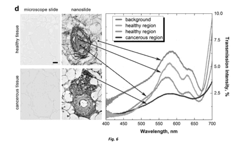
Figure 6 illustrates two pairs of images (arranged horizontally) formed using
embodiments of the present invention illustrating an unstained sample on a
conventional
microscope slide (left) and an unstained sample on a nanoslide (right) in
which colour
contrast can be used to identify structures of the sample. A colour plot
showing the
CA 03121426 2021-05-28
WO 2020/110071
PCT/IB2019/060309
8
transmission intensity (%) over the visible spectrum for selected spatial
positions in the
top series and bottom series of images.
Figure 7a and 7b show two equivalent sections of healthy lung tissue. The top
image is H&E stained, whereas the bottom is the corresponding nanoslide image.
The
scale bar is 5 ,um.
Figure 8 illustrates images collected under identical conditions from breast
cancer
tissue illustrating the relative ease of detecting structures of interest when
colour contrast
is used.
Figure 9 illustrates a comparison of H&E staining, immunohistochemical
detection,
and imaging using a nanoslide for lung tissue with breast cancer metastasis.
Figure 10 shows a further comparison of H&E staining to methods using a
nanoslide for detecting cancer cells in lung tissue sections with a breast
cancer
metastasis.
Figure 11a and 11 b illustrate schematically the pathology workflow for small-
animal, MMTV-PyMT mouse model study.
Figure 12 shows large field-of-view (3.8 mm) sections of corresponding slices
of
H&E, Ki67, and nanoslide images (top to bottom), with the bottom row showing
portions
of the images identified to be positive for neoplastic cells. Regions with HSL
values
consistent with neoplastic MMTV-PyMT breast cancer cells are shown in light
blue
(nanoslide) and bright green (Ki67).
Figure 13 shows an example output indicating the identification of a structure
the
identification of small-animal data based on HSL colour space and assessment
by a
breast-cancer pathologist.
Figure 14 illustrates an example range of HSL colour space values
corresponding
to cancer positivity in PyMT models using nanoslide.
Figure 15 illustrates H&E images for neoplastic regions ¨ identified by the
yellow
outline (1st column) ¨ and relative intensities of nanoslide and Ki67
positivity
CA 03121426 2021-05-28
WO 2020/110071
PCT/IB2019/060309
9
Figure 16a, shows the output of regions evaluated by an expert breast cancer
pathologist plotted as a function of luminosity (L) versus hue (H). Figure
16b, shows the
percentage of cells positively identified as being cancerous on the basis of
HSL colour
space values. Figure 16c, shows pathology scoring of Ki67 and nanoslide images
for
data collected from 24 mice, the percentage of cells identified as cancerous
is indicative
of the tumour stage. Figure 16d, shows the agreement of Dice coefficients for
nanoslide
and Ki67 for three different classes of neoplastic region.
Figure 17 shows an example implementation of an embodiment of the present
invention used to detect a structure in human cells. In this case the
structure are
cancerous cells.
Figure 18 shows of Nanoslide to distinguish normal, benign and cancer
pathologies in human breast epithelial cells.
Detailed description of the embodiments
The present inventors have further realised that the colour contrast exhibited
when
a nanoslide is used in optical microscopy may enhance the ability to perform
histology
and pathology. In particular embodiments, the use of a nanoslide enhances the
ability to
rapidly identify structures in the sample as structural differences are
presented in
contrasting colours, typically without needing to stain or label the sample.
In other
embodiments, use of a nanoslide may enhance the ability to see structures in a
sample
by selectively exhibiting colour contrast in a portion of a sample, the
portion of the sample
that selectively exhibits colour contrast is that portion (e.g. planar region)
within a
characteristic decay distance from the sample holder. In contrast conventional
optical
microscopy that uses stains or dyes to enhance or cause intensity contrast in
a sample
when it is illuminated show use the whole thickness of the sample to generate
that
intensity contrast. This has the disadvantage that the view of the sample (or
image taken
thereof) is in effect a two-dimensional projection of the total light
absorption through the
whole thickness of the sample. This can have the effect of obscuring detail in
the sample
in the image. In contrast, histology with a nanoslide only induces colour
contrast in a
portion of the sample nearest the sample holder and thus may usefully show
structures
with a size smaller than conventional microscopy relying on staining or
labelling alone to
generate an intensity contrast in the received light. See, for example, the
pair of images
shown in figures 7a and 7b. As can be seen the nanoslide derived image has
qualitatively
CA 03121426 2021-05-28
WO 2020/110071
PCT/IB2019/060309
sharper images, in addition to demonstrating colour contrast between locations
in addition
to intensity contrast.
Figures la shows an embodiment of a sample holder used in an example of the
present disclosure. Figure la shows a cross section through a sample holder
suitable for
5 use in the present invention. The sample holder 100 includes a substrate,
on which is
deposited a plasmonic layer 102. Figure lb and lc show the two types of
plasmonic layer
102 with sub-micron arrays of that have been fabricated and may be used in an
embodiment. The layers are each 150 nm thick silver films, although other
suitable
materials can be used. Figure lb has sub-micron arrays in the form of circular
shaped
10 nanoapertures with a 450 nm period arranged in a hexagonal pattern.
Figure 1 c has
cross-shaped nanoapertures on a rectangular pattern. The cross-shaped
nanoapertures
have a 450 nm period in one direction (defined here as the 0 direction) and a
400 nm
period in the orthogonal direction (defined as the 90 direction). These
arrays have a
Surface Plasmon Polariton (SPP) resonance mode in the 470-550 nm range, (which
is
.. within the visible region of the electromagnetic spectrum). To protect the
surface of the
plasmonic layer 102, a layer 104 (10nm 1nm) of hydrogen silsesquioxane (HSQ),
a
glass-like material, is deposited after fabrication of the plasmonic layer
102. After capping
with HSQ, the sample holder 100 has an upper surface similar to that of a
conventional
microscope slide on which a sample may be supported. In use, the HSQ layer
also
presents a polar surface which aids tissue adherence.
Samples to be imaged are prepared and placed on sample holders in accordance
with an embodiment of PCT/AU2018/050496 in the name of La Trobe University. A
sample 106, typically a slice of a biological tissue, which need not be
stained or labelled
in the preferred embodiment of the present invention, is placed on the sample
holder
.. adjacent the plasmonic layer, as shown in figure 2A.
Figure 3 is a schematic representation of a system 300 configured to perform
methods according to the present disclosure. In overview the system 100
includes a
microscope 310 adapted to receive a sample holder 100. The microscope can
capture
images in transmission or reflection mode. The sample holder 100 is a
nanoslide (a
sample holder made in accordance with an aspect of PCT/AU2018/050496) having a
plasmonic layer. The sample 106 that is to be imaged is positioned on the
sample holder.
In some embodiments the microscope is a conventional optical microscope with
eyepieces for viewing by a user, however it can alternatively or additionally
include an
CA 03121426 2021-05-28
WO 2020/110071
PCT/IB2019/060309
11
image capture system to generate a digital image for display, storage or other
later use.
In some forms the microscope 310 can form part of an automated slide scanner.
The
exemplary system 300 illustrated includes a user terminal 312 for display of
captured
digital images of the sample, and a data storage system for storing captured
images.
Figure 4 is a flowchart illustrating steps of one aspect of the present
disclosure that
can be used to identify a structure in a sample, such as the sample 106 of
figure 2a, 2b
or the like. The method begins at step 400 by applying the sample 106 to a
nanoslide.
The slide and sample holder are illuminated as set out herein at 402 and an
image is
formed. Optionally the image is captured in digital form in step 404.
Following this, the
image as perceived directly by a user or as captured in step 404, are analysed
and one
or more structural features in the sample are identified at 408. The analysis
406 and
identification 408 steps can be performed either by a person or in an
automated fashion
as set out in the applicant's co-pending Australian patent application
2018904551, filed
on 29 November 2018, entitled "Automated method of identifying a structure"
and the
International patent application claiming priority to AU2018904551 which was
filed on the
same day as present application,
The analysis step 406 is performed using at least the colour exhibited in the
image.
In the present invention, the colour at a particular location in the image is
representative
of a local physical property of the sample. In particular, by using a sample
holder having
a plasmonic layer including a periodic array of sub-micron structures a colour
contrast is
exhibited which encodes the localised dielectric constant in the sample. The
analysis is
performed to identify features in the image that are representative of one or
more
structures of interest in the sample. A structure of interest can, for example
include, a cell,
group of cells, part of a cell, interstitial space between cells, void in a
cell, the morphology
of any of the above. Most preferably the features of interest and/or
structures are
indicative of the health of the sample.
The underlying mechanism for the extraordinary optical contrast in the images
is
the resonant interaction of light with the collective oscillations of free
electrons at a metal
surface in the plasmonic layer of the sample holder, known as Surface Plasmon
Polaritons (SPPs). The spectral change in transmitted light through an array
of sub-
wavelength apertures in contact with a dielectric specimen is a function of
the wavelength
shift, AX, of the SPP resonant modes Aospp, where superscript 0 denotes the
incident
polarisation angle (the symbol is removed for unpolarised light) and the
subscript
CA 03121426 2021-05-28
WO 2020/110071
PCT/IB2019/060309
12
indicates whether the dielectric constant is for the sample (d = s) or for air
(d = a). The
SPP modes are characterised by peaks in the transmission spectra, the
corresponding
wavelength shift relative to air when a sample of thickness t is placed on top
of the
nanoapertures is given by:
AA A.--,(A0sPP,s-A0sPP,a)(1-exp(-2t//d)), (1)
where la-A/2\1Ed is the characteristic decay length of the SPP electromagnetic
field,
which is itself a function of Ed, the dielectric constant of the sample. It
should be noted
however that in the preferred embodiments the sample is significantly thicker
than the
characteristic decay length of the sample. This is illustrated in the example
of figure 2b.
In this example the characteristic decay length la is indicated by reference
number 110.
As can be seen the sample 108 on the sample holder 100 is thicker than the
decal length
110. As the film thickness increases, the transmission SPP resonance peak is
increasingly red-shifted until it equals Aospp, after which no more colour
change occurs. It
follows that, when using a standard transmission bright-field microscope, a
spatially
resolved distribution of colours will result that relates directly to changes
in the local
dielectric constant in the sample. With the local dielectric constant encoded
in the optical
spectrum, a remarkable chromatic contrast effect is produced. This means that
any
structure within optically transparent samples, which previously was difficult
to detect due
to a lack of contrast, is detectable in the visible-light image, by virtue of
the colour contrast
captured in the images. Moreover, and in contrast to conventional optical
microscopy that
uses stains or dyes to induce or enhance intensity contrast in a sample when
it is
illuminated, or in preferred embodiments only generate discernible colour
contrast on a
narrow layer within the sample - less than the characteristic decal length of
the plasmonic
layer. . Conventional microscopy shows intensity contrast throughout the whole
thickness
of the sample. This has the disadvantage (in conventional microscopy) that the
image of
the sample is in effect a two-dimensional projection of the total light
absorption through
the whole thickness of the sample (which may be significantly thicker than
200nm - see
for example the sample of figure 6 which is 4,um thick. This can have the
effect of
obscuring detail in the sample for the viewer. Visually this can smear or blur
the structure
visible in the image. In contrast, histology with a nanoslide only induces
colour contrast
in a portion of the sample nearest the sample holder and thus may usefully
show
structures with a size than conventional microscopy relying on staining or
labelling alone.
See for example Figure 7. As will be appreciated in conventional optical
microscopy,
CA 03121426 2021-05-28
WO 2020/110071
PCT/IB2019/060309
13
thinner slices can ameliorate this problem somewhat, but cause a concomitant
disadvantage that thin slices may not show appreciable intensity contrast with
a thin slice.
Figures 5a, 5b and 6 illustrate several examples of images captured using
embodiments of the present invention and which illustrate the ability to
identify structures
in the exemplary samples. The images are presented as they appear under the
microscope with no staining or labelling.
For these histological samples, transgenic mice were produced by
microinjection
of a 4.7 Kb DNA fragment consisting of 1.3 Kb of MBP 58 sequences and 3.4 Kb
of c-myc
genomic DNA including part of intron 1, exons 2 to 3, and 316 bp of 38
untranslated
sequences19. The 2-50 pedigree carries approximately 10 copies of the
construct on
chromosome 9 and was isolated on the basis of a shivering phenotype evident in
that
pedigree alone, out of seven originally generated. The transgenic mice and
nontransgenic
littermates were perfused through the left ventricle with phosphate-buffered
saline at 37 C
for 2 min, followed by 4% paraformaldehyde/2.5% glutaraldehyde in phosphate
buffer,
pH 7.4 containing 200IU heparin/100 ml. For figure 5b, tissue was left in situ
at 4 C for 1
hr before sections were cut from the optic nerve via microtomy. Tissues were
fixed in 10%
buffered formalin, paraffin embedded and sectioned at 4 pm onto glass slides
or
nanoslides. In Figure 5b the bottommost image pair shows an equivalent sample
that was
subject to toluidine blue staining. The scale bar is 5 ,um.
For figures 5a and 6 mammary glands were isolated from 50 day old BI/6 MMTV-
PyMT positive female mice at a time when spontaneous mammary tumours develop.
Tissues (including those derived from control BI/6 mice) were fixed in 10%
buffered
formalin, paraffin embedded and sectioned at 4 pm onto glass slides or
nanoslides.
The nanoslides used include periodic arrays of nano-apertures were fabricated
using either focused ion beam (FIB) lithography technique (Helios NanoLab 600
Dual
Beam FIB-SEM, FEI) or photolithography (for large areas). A hydrogen
silsesquioxane
(HSQ) protective layer was spun after the array fabrication. HSQ was converted
into
amorphous silicon oxide via exposure to electrons. In other embodiments a
metal oxide
capping layer e.g. SiO2 can be used in place of HSQ. In the example of figure
5b the
periodic array has the structure set out in connection with Figure 1c, which
has cross-
shaped nanoapertures on a rectangular pattern. The cross-shaped nanoapertures
have
CA 03121426 2021-05-28
WO 2020/110071
PCT/IB2019/060309
14
a 450 nm period in one direction (defined here as the 00 direction) and a 400
nm period
in the orthogonal direction (defined as the 90 direction).
Bright-field and DIC data were collected using a Nikon Ti-U microscope system
with a 60x (NA=0.7) objective; spectral data were collected using an !soPlane
SCT 320
(Princeton Instruments) at 1200 gratings/mm. The spectral data were normalized
with
respect to the bare substrate. All images presented here are 'as viewed'
through the
microscope without any image manipulation applied whatsoever. A Bruker
Dimension
Icon AFM was used to collect the topographical data and line scans.
Turning to Figure 5a, which shows two bright-field optical images of unstained
4,um
section of breast tissue. The top image is an unstained section on a
conventional glass
slide. The bottom image is an equivalent section on a nanoslide. Imaging time
was < 1
second. As can be seen in the top image almost no structure can be seen, due
to the
sample being substantially transparent and thus the image displays a lack of
contrast. As
can be readily seen in the lower image, using the nanoslide, structures in the
sample can
be readily visualised due to the colour contrast exhibited in the image. The
colours of
different structures within the sample reflect areas of different dielectric
constant.
Moreover, structures of the same type also tend to appear in the same colour
throughout
the sample enabling reliable identification of such structures,
Figure 5b shows images collected from optic nerve slices that are 70 nm thick.
The
scale bar is 5 ,um. Such sections can typically only be viewed using
transmission electron
microscopy (TEM) and are essentially invisible using conventional optical
microscopy, as
can be seen in the top panel, which shows unstained samples. The second and
third
panels show an image (left) and close up detail thereof (right). The middle
panels show
the image captured with the sample being illuminated with 0 incident
polarisation. The
lower panels show the same sample but illuminated with light having a 90
incident
polarisation. The bottommost panels show an equivalent sample that was subject
to
toluidine blue staining. As expected, little intensity contrast is observable.
It has been observed by the inventors that changing the incident polarisation
direction (which had no effect on the conventional bright-field images)
enabled subcellular
structure of the tissue, such as the myelin sheath which is critical for a
wide spectrum of
pathologies, to be selectively enhanced. This is believed to be due to the
different
periodicity of the sub-micron arrays in a direction parallel to each of the
polarisation
CA 03121426 2021-05-28
WO 2020/110071
PCT/IB2019/060309
angles. The different periodicity is believed to tune the transmission spectra
so that the
colour at which a structure of a given dielectric constant appears changes.
This enables
selective enhancement or colouring of structures with certain properties. It
follows that
that colour tuning of a typical target structure (e.g. cell type) can be
performed by selecting
5 .. the parameters of the sub-micron periodic structure, e.g. one or more of
period, size,
shape, array geometry, so that the target structure appears in a
characteristic colour or
colour band. As will be appreciated this can enhance rapid detection of a
target structure
or determination of its characteristics.
Figure 6 illustrates two pairs of images (each pair arranged horizontally) the
right
10 image of each pair being formed using an embodiment of the present
invention, and the
left illustrating an unstained sample on a conventional microscope slide. The
upper pair
of images show healthy breast tissue. The lower images show cancerous breast
tissue.
As can be seen in both sets of images certain structures of the sample tissue
can
be visualised and hence identified based on the colour differentiation from
adjacent
15 structures. Strikingly cancer cells in the lower pair of images show up
as dark blue on the
nanoslide. As can be appreciated the ability to identify target structures
based on colour
can greatly aid the process of histology. The inventors ascribe this
sensitivity to the cancer
cells having a different cell density, likely due to different amounts of
protein, and
therefore developing a slightly different dielectric constant. This colour
contrast, usually
with along with the change in their morphology can improve the ease with which
(or
likelihood of) correctly identifying the presence of cancer cells. See for
example figures 8
and 9.
A colour plot showing the transmission intensity (%) over the visible spectrum
for
selected spatial positions in the top series and bottom series of images is
also provided.
As indicated the background region, appears to be slightly blue to the viewer.
The spectral
content of this region is shown in the transmission intensity plot by the blue
trace. Healthy
structure appear to be either orange/yellow or green. The spectral trace being
indicated
at right by the orange and green traces respectively. Finally, the cancerous
cells, only
present in the bottom pair of images, appear to be dark blue. The spectral
trace of these
cells is indicated in purple to the right. The resultant perceptible colour of
each spectra
illustrated can be determined using a CIE plot, according to the CIE 1931
colour space.
CA 03121426 2021-05-28
WO 2020/110071
PCT/IB2019/060309
16
As noted above a nanoslide can be used in a method of determining a state of
at
least one cell in a sample at least partially based on the colour of the at
least one cell in
the image. The method can include, determining a disease state of at least one
cell.
Advantageously the sample can contain a cells of the same type and the method
can
involve distinguishing certain cells (or their state) amongst cells of the
same type based
on based a colour contrast between the at least one cell and cells in the
plurality of cells.
This can enable abnormal cells to be distinguishing. In some cases the
abnormal state
can include cancer, benign abnormalities or infection.
The inventors performed the following experiments that demonstrate that use of
the nanoslide could enable determination of variations in cells in a tissue
context and if
benign and neoplastic tissues could be distinguished by label-free CCM. A
particular
focus of the experiment was to determine if a nanoslide could be used to
achieve
comparable levels of cancer cell detection to Ki67 for ductal carcinoma in
situ (DCIS)
which represents 20-25% of all breast cancer cases. Since it fits into
existing pathology
workflows nanoslide could be an ideal adjunct to H&E (haematoxylin and eosin)
staining,
improving specificity to cancer cells and potentially reducing rates of
misdiagnosis whilst
also reducing the tissue preparation time compared to IHC staining
Figure lla and llb together illustrate, schematically the pathology workflow
for
small-animal, MMTV-PyMT mouse model study including, showing how serial
sections
were taken in order for a direct comparison of nanoslide, H&E, and Ki67.
In the study the images made use of the MMTV-PyMT model of spontaneous
breast tumorigenesis, where mice develop pre-invasive and invasive neoplasms
within
50 days of age. Pre-invasive and invasive neoplasms have previously been shown
to be
distinguishable from benign epithelial cells using IHC staining for the
proliferative
marker Ki67. In total 24 mice were used for this study. The workflow for the
study
design is shown in Fig. lla and 11b. For each slice of tissue sectioned and
placed on a
nanoslide the neighbouring section was H&E stained (for use as the ground
truth
analysis by expert human analysis) whilst the next two sections were treated
with IHC
staining (one section with the proliferative marker and the other with control
IgG.
Figure 12 shows large field-of-view (3.8 mm) sections of corresponding slices
of
H&E, Ki67, and nanoslide images (top to bottom); each slice is 4 m thick ( Id
for the
nanoslide). These sections cover a range of different tissues types (e.g.
lymph nodes,
collagen, muscle tissue, ligament etc.) and also include regions of pre-
invasive and
CA 03121426 2021-05-28
WO 2020/110071
PCT/IB2019/060309
17
neoplastic breast tissue. Using the ground truth pathology assessment and the
comparative Ki67 IHC staining the HSL values associated with cancer cells were
identified for nanoslide (see below). Similar approaches have previously been
applied to
segmentation of IHC stained images. Based on the range of HSL values for
cancerous
tissue using both Ki67 and nanoslide, by exploiting the intrinsic properties
of the HSL
colour space we were able to threshold the images to only display neoplastic
tissue.
The results of carrying out this procedure for nanoslide and Ki67 are shown on
the
bottom row of Fig. 12. Note that in the overlayed, large field-of-view
positivity results
there is excellent general correspondence between Ki67 and nanoslide (the two
slices
are separated by 12 pm in the tissue biopsy). This high degree of correlation
between
Ki67 and nanoslide was observed across all of the slides used in this study.
To quantify the performance and correlation between nanoslide and the IHC
staining high-resolution imaging data was collected from the slides. A total
of 64 regions
were examined across the cohort of 24 mice. Following established protocols
tissue
was classified as True Positive (TP), True Negative (TN), False Positive (FP),
and False
Negative (FN) ¨ see Methods. Two key pieces of information were used for
tissue
classification. The first was the pathology annotations, when a cancer
containing region
has been identified, high-resolution H&E stained slides were used to identify
the stage
of the cancer and the margins. A morphological assessment of the tissues was
conducted by an expert human breast and murine mammary gland pathologist
(O'Toole) and breast cancer researcher (Parker) and formed the 'ground truth'
for the
analysis presented in Fig. 13. Classification was applied according to the
following
descriptions.
Classification Description of classification method
for Ki67
and Nanoslide
True Positive (TP) TP was assigned when the HSL colour
space
values were consistent with cancer cells
established by 'training' the segmentation
algorithm. This 'training' was conducted based
on the identification and correlation of
cancerous tissue in Ki67 and nanoslide images
by the expert pathologist with reference to
the H&E slides (e.g. Shi et al, Scientific
Reports, 2016). To be classified as TP also
required that the identified region was within
the area manually identified as containing
cancer cells by the expert pathologists.
CA 03121426 2021-05-28
WO 2020/110071
PCT/IB2019/060309
18
True Negative (TN) TN was assigned when the HSL colour
space
values were consistent with one of the sub-
types of non-cancerous tissues (e.g. adipose
tissue, collagen, lymph nodes, blood vessels
etc.). To be classified as TN also required that
the identified region was outside of the area
manually identified as containing cancerous
tissue by the expert pathologists.
Fake Positive (FP) FP was assigned when the HSL colour
space
values were consistent with cancer cells but
the identified region was outside of the area
manually identified as containing cancer cells
by the expert pathologists.
Fake Negative (FN) FN was assigned when the HSL colour
space
values were not consistent with either cancer
cells or with non-cancerous tissue and when
the identified region was within the area
manually identified as containing cancer cells
by the expert pathologists.
The second piece of information came from the image pixel HSL colour space
values which were compared against the reference values from the training
data.
Regions containing normal, hyperplasia, DCIS (ductal carcinoma in situ), and
invasive
neoplastic breast tissue were independently analysed for both nanoslide and
Ki67
staining. Some example images of each type of region and resulting tissue
classification
are shown in Fig. 13. The images (1st and 3rd columns) are presented as they
appear
under the microscope. Confirming the results of the large field-of-view
positivity analysis
(Fig. 12, bottom row), neoplastic cells in pre-invasive and invasive
neoplastic tissues
were easily distinguished from surrounding cells in the same tissue and benign
tissues
via a colorimetric differential interaction as a result of either staining
(Ki67 ¨ brown
colour) or as a result of variations in the local dielectric constant
(nanoslide ¨
blue/purple colour). As seen from Figs. 12 and 13, adipose and other types of
non-
cancerous tissue observed across the slides have a characteristically
different colour
(HSL) on both the nanoslide and Ki67, supporting this association. . As can be
seen in
figure 13 the normal cells on the nanoslide appear to be almost uniformly
categorised
as TN. The invasive cells image on the nanoslide image was categorised as a
large
majority of TP regions surrounded by TN areas, showing accurate categorisation
by the
automated image analysis. The DCIS and Hyperplasia images include a region of
majority TP towards the centre of the neoplastic regions surrounded by areas
of mixed
FN, TP, TN regions.
CA 03121426 2021-05-28
WO 2020/110071
PCT/IB2019/060309
19
For both the nanoslide images and Ki67 images the mean RGB space and HSL
space values for the cancer cells were determined from the ground truth
standard.
Cancer cells when imaged on the nanoslide manifest themselves as generally
blue in
hue, whereas, Ki-67 positive nuclei manifest themselves as brown hue in images
of breast
tissues.
The mean RGB and HSL channel values for positive cancer cells in Ki67 and
nanoslide are summarised in Table 1. The RGB values for Ki67 positivity
determined by
the inventors are close to the published values from (Shi et al., Scientific
Reports, 2016).
............................................................................
Vafues
R G B H S L
.................................................................
IIIIPPOOOMMI 123 51 7 23 89 26
. . . . . . . . . . . . . . . . . . . . . . . . . . . . . . . . . . . . . . .
. . . . . . . . . . . . . . . . . . . . . . . . . .
Nanostide (blue) 23
69 86 196 58 21
Table 1
Based on the variability of the colour change associated with cell positivity
in nanoslide
and Ki67 a 15% threshold centred around the mean HSL colour space values,
(for each
of H, S, and L) was used for segmentation of positive cancer cells ¨ that is,
within this
range cells were considered to be 'positive for cancer. An example range of
HSL colour
space values corresponding to cancer positivity using nanoslide is shown in
figure 14.
To further validate the results against published standards the inventors used
an
established scoring matrix for discriminating 'normal', hyperplasia, DCIS and
invasive
lesions. As revealed in results presented in Fig. 15, both approaches
(nanoslide and Ki67)
identify a similar percentage of neoplastic cells in a randomised preclinical
study. For
DCIS using H&E alone there is a low rate of concordance among pathologists.
DCIS
comprises lesions which are heterogeneous with highly variable morphology.
Whereas at
the extremes of normal and invasive, breast cancer is easy to discern, DCIS is
subtle and
consequently suffers from misdiagnosis based on H&E alone particularly at
large fields-
of-view.
Across the small animal models studied the measured values (HSL) corresponding
to cancer cells in Ki67 and nanoslide are almost entirely confined to the
cancer specific
CA 03121426 2021-05-28
WO 2020/110071
PCT/IB2019/060309
regions (or those that are pre-cancer lesions in this model ¨ hyperplasia). In
other types
of tissue the colour is sufficiently different that these other tissues could
not be mistaken
for cancers by either a pathologist or by automated image analysis.
Figure 15 illustrates the absolute difference between the image pixel HSL
colour
5 space values and the mean values for positive cells. x is a metric used
to define the
similarity of the image pixel HSL colour space to the selected reference HSL
colour space
based on the median values pre-determined for cancer cells. (See table 1 for
mean HSL
values).
x = v(I-I Ilm)2 + 5M)2 (L Lm)2
H, S and L are pixel values in the HSL colour space and HM, Sm, Lm, are mean
values from table 1. Note, however, that this does not necessarily reflect the
contrast
perceived by the human eye when examining these samples under the microscope.
The methods disclosed herein use utilise the differences in the spectral
output
between structures to identify those structures. Figure 6, illustrates the
received colour
spectrum of benign and neoplastic breast tissue which giving rise to colour
contrast in
nanoslide images. On the basis of the 24 MMTV-PyMT mice studies the spectral
output
of cancer cells appears to be distinct from other types of non-cancerous
tissue providing
a novel mechanism for performing digital pathology. To further validate the
results
against published standards the inventors used an established scoring matrix
for
discriminating 'normal', hyperplasia, DCIS and invasive lesions. As revealed
in results
presented in Fig. 16a (which relate to the sample of figure 6), both
approaches
(nanoslide and Ki67) identify a similar percentage of neoplastic cells in a
randomised
preclinical study. DCIS comprises lesions which are heterogeneous with highly
variable
morphology; whereas at the extremes of normal and invasive, breast cancer is
easy to
discern, DCIS is subtle and consequently suffers from misdiagnosis based on
H&E
alone particularly at large fields-of-view.
Fig. 16a shows how the automated method described herein using a nanoslide
sample holder discriminates between structures in a sample. In this case it
has been
shown that 'healthy and invasive cancer tissue can be identified based in the
hue (H, )
and luminosity (L, /0) of the images. Note that the 'healthy' tissue sections
are taken
from MMTV-PyMT mice, 90% of which will eventually develop pre-invasive and
invasive
CA 03121426 2021-05-28
WO 2020/110071
PCT/IB2019/060309
21
neoplasms, hence a small amount of overlap may be expected when comparing to
invasive cancer regions. The difference between normal and cancer mammary
tissue is
further validated by the clear discrimination between normal/benign tissue in
wildtype
animals and neoplastic tissue.
To test the concordance of Ki67 and nanoslide we compared the percentage (by
area) of tissue identified by the two pathologists as containing neoplastic
cells according
to the image pixel HSL colour space values; the results are summarised in
Figure 16b.
For the regions examined (N=30) nanoslide and Ki67 exhibit highly positively
correlated
performance metrics. The Pearson correlation coefficient, r, and corresponding
p-value
for the Ki67 and nanoslide results confirm a positive correlation: r(28)= .62,
p<.001. Of
the cancer bearing tissues examined none had both non-zero Ki67 positivity and
zero
nanoslide positivity and only two had non-zero nanoslide positivity but zero
Ki67
positivity. Figure 16c, shows pathology scoring of Ki67 and nanoslide images
for data collected
from 24 mice, the percentage of cells identified as cancerous is indicative of
the tumour stage.
The positive correlation between Ki67 and nanoslide supports the breast cancer
pathologists' manual scoring (Fig. 16c) and concurs with Figure 16d that shows
the
Sorensen¨Dice coefficient (DSC) coefficients for nanoslide and Ki67 for three
different classes
of neoplastic region. The DSC is defined as:
DSC=2TPA2TP+FP+FN)
Calculated for both nanoslide and Ki67 (Fig. 16d) based on the analysis of 64
high-resolution (200 x magnification) images from both Ki67 and nanoslide
data.
Pathology assessment
In the example to confirm the timing of spontaneous development of mammary
gland tumours in the C57 BI/6 MMTV-PyMT model, mammary glands of C57 BI/6
MMTV-PyMT mice at different stages were taken and morphologically evaluated by
H&E and Ki67 by an expert human breast and murine mammary gland pathologist
(O'Toole) and breast cancer researcher (Parker). Nanoslide samples were
randomized
and independently scored and then compared post-analysis to the results of
Ki67 and
nanoslide. The benchmark for the pathology assessment was a trained
pathologist
analysing the H&E stained tissue sections at high-resolution and without any
time
constraints. As this was a control study the cancer stage for the mice was
already
known by the pathologist. In addition, the pathologist could refer back to the
IHC
staining to confirm that no neoplastic tissue regions were missed during the
CA 03121426 2021-05-28
WO 2020/110071
PCT/IB2019/060309
22
assessment. When looking at a tumour region or duct containing cancer at high
resolution the pathologist counts the number of cancer cells.
Once this has been done for all samples the pathologist then compared the
number of individual positive cells (as determined by a colour change ¨ 'brown
for Ki67
and 'green/blue' for nanoslide) using either Ki67 or nanoslide and divided
this number
by the total number of cancer cells identified from pathological assessment of
the H&E
images to arrive at the final figure for "percentage positive cells". This
analysis was
conducted on 24 cancer containing regions across the 24 mice used in this
study.
Based on the knowledge of the cancer stage the results could be classified
into 4
stages: 'normal', typerplasia% DCIS', and 'invasive'. The mean value of the
percentage
of positive cancer cells as determined by the pathologist was calculated
within each
category, it is this mean value, averaged between the two independent sets of
scores,
which is represented by the height of the bars in the bar chart. The range
(e.g. minimum
and maximum percentages) over the different samples used to generate the error
bars
.. shown in Fig. 10d. The scoring matrix for discriminating normal, DCIS, and
invasive
lesions is shown in the following table
Normal DCIS Invasive
Appearance of lumen Empty Lumen Filled Lumen No Lumen
Epithelial Ki67 positivity 0-28% 44-66% 48-96%
(95% confidence interval)
The methods disclosed herein can include distinguishing at least one cell
having
an abnormal state within the plurality of cells, including enabling a
distinction to be seen
between benign abnormal states and healthy states. For example the method can
provide
a method of distinguishing normal breast tissue from a benign
abnormality/state, such as
hyperplasia, within a population containing a plurality of breast epithelial
cells. Figure 17
shows an example implementation of an embodiment of the present invention used
to
detect a structure in human cells (top row), compared to corresponding images
taken with
IHC staining (middle row) and H&E staining (bottom row). Serial sections of
normal
CA 03121426 2021-05-28
WO 2020/110071
PCT/IB2019/060309
23
reduction mammoplasty, hyperplasia or ductal carcinoma in situ human tissue
were
hematoxylin and eosin stained, IHC stained for proliferative marker Ki67 (both
on glass
slides) or placed on the nanoslide (stain-free). Light microscopy was used to
visualise
tissue morphology and colour. As discussed above brown colouring in the middle
row
indicates Ki67 positivity. Differential colour appearance of cells in the
nanoslide images
indicates the state of the cells, and in particular the presence of cancer
cells appear
blue/purple as noted above.
Figure 18a shows the image illustrating DCIS in breast tissue imaged with CCM
from figure 17, whereas 18b shows the image illustrating DCIS in breast tissue
imaged
with IHC staining from figure 17. In each image the right hand panel shows a
segmented
image that identifies portions of each captured image having a colour within
15% of the
mean colour of cancer for the sample (see figure 14 for the CCM colour range,
and table
1). As can be easily observed significant numbers of differentiated cells can
be observed
in the CCM image. This compares favourably in to IHC staining based on
proliferative
markers (figure 18b) which positively identifies few cancer cells.
As will be appreciated the identification of cancer and other disease may be
based
on subtle changes in cellular morphology such as alteration to the cell
cytoskeleton and
nucleus. This Includes cell symmetry, shape, nuclear
pleomorphism/organisation.
Distinguishing cell types may be based on cell size, shape and tissue
organisation. Use
of embodiments of the present invention may allow enhanced visibility of such
characteristics and structures. Moreover, when morphology is
decreased/compromised
(due to tissue preservation/preparation techniques or when there are only very
few cancer
slides present that become difficult to find) it is very difficult to make
accurate diagnoses
of cancer based in morphology alone. In such situations embodiments of the
present
invention may still offer colour contrast as a distinguishing feature. That is
colour contrast
can still be visible when larger scale morphology is compromised. The examples
presented herein indicate that the colour of cells may be different in cancer
cells
compared to non-cancerous cells.
Figure 8 illustrates images collected under identical conditions from breast
cancer
tissue using the following techniques:
CA 03121426 2021-05-28
WO 2020/110071
PCT/IB2019/060309
24
(left column) A nanoslide in accordance with an embodiment of the present
invention. These images were collected in a few seconds with no staining,
labelling or
image enhancement.
(Middle column) H&E staining ¨ the most widely used current standard for
tissue
imaging.
(Right column) Brightfield microscopy of the same unstained sample.
After image collection analysis is performed to identify structures of
interest (e.g.
cancer cells). In the nanoslide images cancer cells could be instantly
identified by the
pathologist due to them appearing in a dark green/blue colour in the image,
which made
their morphology stand out clearly with respect to the background. The same
analysis,
however, using standard H&E approaches was much more challenging due to the
uniform
colour of the stain which makes a clear differentiation from the surrounding
healthy cells
difficult. Using a H&E stain may lead to a high rate of misdiagnosis for many
early stage
cancers due to the difficulty in differentiating cancer cells form healthy
cells.. In the images
the scale bar is 5 m. As expected, the unstained sample does not show any
useful
contrast.
Using conventional optical microscopy, it is difficult to determine if a cell
is likely to
be invasive or metastatic. Given that metastasis is responsible for patient
mortality,
diagnostics that may distinguish invasive cancers or those most likely to
metastasise can
offer something not currently available in pathology.
Figures 9 illustrates the relative ease of using an embodiment of the present
invention for this purpose. As will be appreciated, cancer cells are not
normally easily
detected with H&E; however, they can be differentiated via immunohistochemical
methods (which typically takes two days post sectioning) and via use of a
nanoslide
imaging technique as described herein (which takes a few seconds post
sectioning).
Figure 9 shows three rows of two images. In each row the right image is at low
magnification and the left shows a close up of a region including a cancer
cell. The top
row is a sample that is subject to H&E staining. The middle row is subject to
anti-mCherry
immunohistochemical detection. The bottom row is an unstained sample placed on
a
nanoslide. An enlarged region showing the cancer cells on a nanoslide is shown
in figure
10. The scale bars are 5 ,um. Figure 10 shows further detail of H&E stained
lung cancer
CA 03121426 2021-05-28
WO 2020/110071
PCT/IB2019/060309
tissue section (note that this is not normally used as a diagnostic test for
this type of
cancer). In the corresponding CCM image, the cancer cells (confirmed by a two-
day
immunohistochemical detection procedure) are indicated by the red arrows.
Using a
method as describes herein these could be readily identified by the
pathologist, as a result
5 of the colour contrast showing them in a deeper shade of brown to other
cells.
The majority of breast cancers arise in the ductal epithelium. It can be
difficult to
distinguish different states in epithelial cells- including normal,
hyperplasia (a benign
abnormality) and the earliest stages of cancer. This is very important in
accurate patient
diagnosis, monitoring and treatment (including deciding on surgery). The data
presented
10 above illustrates that epithelial cancer cells can be distinguished by
the blue/purple
appearance on nanoslide. This appearance distinguishes cancer cells from other
cells in
the same tissue, but also distinguishes cancer versus benign or normal
epithelial cells
across different tissues. Together, this supports the ability for methods
disclosed herein
to enable the distinguishing (by human or computer implemented analysis) of
different
15 .. states of the same cell of origin (which may have relevance to various
diseases including
cancer and infection).
Moreover, some embodiments of the present invention do not require the
histologist and pathologist to use any special equipment or training (in
addition to what
the slide preparation and pathological visualising and assessment already
used). The
20 nanoslide resembles a conventional microscope slide. Hence, CCM can
integrate into
existing pathology workflows (including using conventional microscopes for
visualisation)
but provide the pathologist with high contrast images. In particular, for
cancer CCM
provides 1HCS-like' images without requiring any additional staining or
preparation.
In a clinical setting a standard IHCS takes 4 hours; using CCM the
results/images
25 are obtained as soon as the sample goes under the microscope. Some
pathologist will
examine 200-300 samples per day. In 5-10% of hard-to-diagnose cases (including
early-
stage cancers) additional special stains are requested representing a
significant
disruption to workflow and cost in time waiting for a more definitive
diagnosis.
It will be understood that the invention disclosed and defined in this
specification
extends to all alternative combinations of two or more of the individual
features mentioned
or evident from the text or drawings. All of these different combinations
constitute various
alternative aspects of the invention.