Note: Descriptions are shown in the official language in which they were submitted.
CA 03121811 2021-06-01
WO 2020/131782 PCT/US2019/066707
RELEASE. MECHANISM FOR.MECHANICALLY LOCKED WIPER.K.44;1 SYSTEM.
CROSS-REFERENCE to RELATED. APPLICATIONS.
The present application claims priority to 11S, Provisional Application Serial
No..
.62/7$.3,02. filed on December 21, 2Oi8 and U.S. ProViSional App I i cation
Serial No 62/fll 4679
tiled on February 21 201 9 .which are incorporated herein by reference in
their entirety.
TECHNICAL :FIELD
The present disclosure relates .generally to release. systems for mechanically
locked
downhole tools and, more particular:Iy, to release mechanisms for mechanically
locked Wiper ping
systems,
.BAcKGROUND
When drilling well,. a :borehole is drilled typically from the earth! s
surface ip a selected
depth, in mtny applicationsõ. the .wellbore iS lined with a string: :of easing
to add support :(9 the
wejtore !sothatir does. not collapse,. For deep well boresõ. the wellbore Is
often drilled in !Set.liOdti
With successiyely deeperscotiOns haying smaller diameters. .A drill bit is
passed through :the initial
eased borehole and then is: used to drill a: .sinaller diameter borehole to an
even greater depth. A
smaller diameter casing May then. he suspended and ceinent0 in place: within
the new borehole.
typically, this is repeated until n plurality of eoncentric: cmitip .43.e
suspended. and. cemented
within the well to .4 depth which causes the well to extend thivite,h one or
more hydrocarbon
producing formations,. Rather tha.n .suspending a coneentric casing from
tbehottom of the borehole
to the surtax, a liner is OMNI suspended adjacent to the lower end of the
previously suspended
easing,. or from. a. pi7eviously suspended.: and cemented liner, :so as 14
extend. the liner from the
previously Set ea:sit-Igor liner to the bottom ofthe new borehole: A liner- is
defined as casing that
:j riOt-run to the surface.
Qnee the. liner is .pluced in the borehole, a. gap exiSts between the liner
and the bOrehole,.
called: an :annulus, which :must .be filled with cement- in order to secute
the liner :in: place. TO
accomplish this, cement is pumped down: the bore of the l
:thus forming a travelling :cement
cOltimn. After reaching the bottom opening Odle liner, theeement column is
continua Hy pumped
so that it exits the liner, spreads outward,: and travels up.the annulus.
During :the cementing operation, after the cement is pumped into the borehole,
the cement:
column is pumped :down the borehole by way (WA pressurized drilling fluid,
Without the use Of
1
CA 03121811 2021-06-01
WO 2020/131782
PCT/US2019/066707
any separation devices, the cement column would rnix with the prosurized
drilling fluid abow
and with fluid already in the borehole below, which would dilutt. or otherwise
Comprornise he
integrity of ithe cement; To prevent this., hpor wiper plugs: are used to
separate the: (valeta :column
from the fluid hhove and below the column and to clean the inside of the
casing liner of any
:drilling fluid Or other downholc fluid. Cetnentin, operatiom may use: a
single plug, placed above
or below tbe.,:eolumn, or two plugs with ohe placed on either end of the
cement eplumn, The: Oper
plug has flexible wings that wipe the inside 6mm-dere:nee of the liner. ,and
create a seal between
the cement on one side and the fluid on the other.
Once the: Lenient eplunm is pumped into the annulus, a liner wiper plug can be
released
to from the running todi to which it is attached, There are many typo: of
rejpase mechanisms for
liner wiper plug sySterns. Improwelnents. to existing liner NV iper plug
rele:aw systems are desired,
2
CA 03121811 2021-06-01
WO 2020/131782
PCT/US2019/066707
BRIEF DESCRIPTION OF TUE DRAWINGS
For .a more complete understanding of the present disclosure and its features
and
advantages, reference is now made to the following description, taken in
conjunction with the
accompanying drawings, in which:
NG 1 is a longitudinal cross,leetional view of a liner wiper plug system:
before an
actuation sleeve is shifted, in accordance with an embodiment of the .present
diselosure;
FIG. 2A is a longitudinal cross-sectional- view of the liner Wiper plug
system:, shown in
FIG.. I, after the actuation :sleeve- is shifted, in accordance with an
embodiment of the present
disclosure;
WI. 213 is a longitudinal crossseetional view of liner wiper
plug system, shown in
FIG, I, after the liner wiper plug detaches fully from the release mandrel, in
accordance with. an
embodiment of the present disclosure;
HQ. 2C is an -outside view of a liner wiper plug system showing a jaw clutch,
in
accordance with an embodiment cyf the present disclosure;
IS
FIG.. 3 is a longitudinal side view of an actuation sleeve separate from. any
liner wiper
plug system,. in accordance with an embodiment of the present disclosure;
FIG. 4- is an enlarged side .devational view of a release sub and actuation
sleeve before
the actuation :sleeve is shifted,, in accordance with an embodiment of the
present disclosure;
FIG. 5 is An enlarged side devational View of the. release sub and actuation
sleeve-, shown
in FIG. 4, after the .actuation. sleeve is shifted, in accordance with an
embodiment of the present
disclosure;
FIG. 6 is an up-hole, eross-sectionolview.of the interaction between a mandrel
andrelease
sub before the actuation sleeve is shifted, in accordance with an embodiment
of the present
disclosure;
75 FM.
7 is an up-hole,. cross-sectional view of the interaction between the mandrel
and
release sub, shown in FIG. 6, after the actuation, sleeve- is. shifted, in
accordance with an
embodiment of the present disclosure;
FIG. & is a partial cutaway outside view oft colleted release sub and is -
shown removed
from any liner wiper plug system, in accordance with an embodiment of the
present disclosure;
KG. 9, is a longitudinal cross-sectional view of a liner wiper plug system
before an
actuation sleeve is shifted,. in accordance. with an embodiment of the present
disclosure;
PIG, 10 is. a close-up view ea longitudinal cross-sectional view of a liner
wiper plug
system, shown in FIG. 9, before an actuation sleeve is shifted, in. accordance
with an embodiment
3
CA 03121811 2021-06-01
WO 2020/131782 PCT/US2019/066707
of the present disclosure;
FIG, LI is a close-up view of a longittulinal cross-sectional view of the
liner wiper plug
system. shown in FIG. .9, after the amta don sleeve is shifted, in accordance
with an embodiment
of the present disclosure.; and
Fla. 12 ii a lonuitudinal cross-seetional view of the liner wiper plus system,
shown in
FIGS :9 after the liner wiper plug detadhes fully from the release mandrel, in
accordance with an
embodiment of the present disclosure,
4
CA 03121811 2021-06-01
WO 2020/131782 PCT/US2019/066707
PETAILM DESCRIPTION.
IllustratiVe embodiments of the present disclosure are described in detail
herein, in the
interest of Clarity, not all features: of an actual implementation are.:
described in -this specification,
it will of course:be appreciated that in the development of any such actual.
embodiment. numerous:
implementation specific deeiSiOns must: be made to achieve developers:'
:specific gpals, su-ch as
compliance with system related and business-related eonstraints,. 'Which Will
vary from one
implententatioa to another'. 'N/loreoyerõ it will be appreciated that such a
development effort !nigh(
be, comple& and time consumingõ but would nevertheless be a routine
undertaking for those. of
ordinary skill in the art having the benefit of the present disellosure,
furthernlore, in no way should
the following examples be read to I bilk ordefine, the scope: of the
disclosure,.
The following disclosure relates to a pivoting release mechanism -that
utilizes. utilize a:
Shifting skew to rotate or pivot a release sub, thus -disengaging a. load
,..botilder And releasing the.
plug 1$ystein.. In some: embodiments, the plug ..system may be mechanically
lOcked to a: running
tool via eorresoonding g totted load shoulders in the: run lllllllllllll and
on a. release sub. The release
sub may be Connected to an actuation sleeve Via. .5.4100 $orrOWs: or other:
temporary: Securing
mechanism. Furthermore, the actuation sleeve may eontain a guide consisting of
helical slots'
which into-met with the release sub shear SCEOWS.
following disclosure relates 41.;i0 to a retracting, colleted release gub
.N.W1C re the collets:
aro,. initially, propped up by 4 raised surfnee on the outer diameter surface
of an actuation sleeve::
An adjacent groove, or 4 lowed surfaze, on the aetuation :sipeyes'allOws-tbe
collets to contract in
the event that theactnation sleeve. shifts,
In some einhoditrients, when releasing the .wiper plug sysietri, a drill
pipet:mine:ming dart
may land in the actuating. sleeve, -thus shifting the sleeve downhole, in
.turn, the axial motion ot.
thg actuation sleeve, may romp the guide pins to rotate within, the helical
guides, thereby pivoting
the releasesub: At comgletion.ofthe :ph,ot8 the load shouldersof the
release sub may be aligned
with The lots in the running. tool load shoulder, allowing. the mime atib to
move down/tole,:
thereby releasing the ijing system
..A.53 a person ofordinary skill in the art would :appreciate, The discloged
:release system eau
bea4.1apte0caOly to beusedwitttany 00w-4101e running tool. In Some embodiments-
, the downbole
10 1 that uses IN disclosed! -release system, is. 4 liner wiper plug. Other
down:hole tools., used. in
other embodirpon04, include but are not limited to easing cement plugs,liner
hanger running tools,.
squeeze: tool; and go forth.
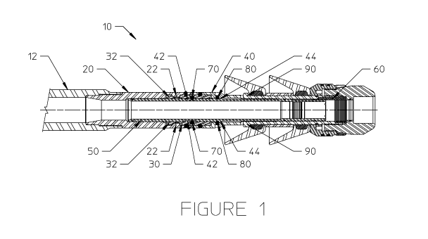
Turning nowt). FIG-. I , in some enthOdiments: the liner wiper plegsystom 10
may include
5
CA 03121811 2021-06-01
WO 2020/131782
PCT/US2019/066707
four major components: the release mandrel 20, the -re-lease sub 30, the liner
wiper plug body 40õ
and the actuation sleeve 50. Some embodiments may also use a key .60 and shear
screws 80.
The release mandrel 20, may be directly connected to the :bottom a a running
tool: 12 or
may be an integral part of the running tool 12. Release.mandrel 20 may have at
least one slotted
inner-circumferential load shoulder -22. The release sub 30 may contain, at
least one slotted outer-
circumferential load shoulder 32 that may interact, with at least one inner-
circumferential load.
shoulder 22 of release mandrel 20, The slots of the at least one inner-
circumferential load shoulder
22 of the release. mandrel 20 may be larger than the outer-eircum&rential load
shoulder segments
:32 of the release sub 30. When running downhole, load shoulders 22: and 32
may be oriented such
10- that axial load can be transmitted between release mandrel 20 and
release sub 30.
The liner wiper plug body 40 may be the main mandrel of the liner wiper plug
system 10
and may house any components required for the liner wiper plug system 1-0 to
function properly,.
excluding components required .for release operations. The liner wiper plug
body 40 may be
clutched to the release mandrel 20 to prevent relative rotation between the
two parts. The
embodiment in FIG. I may use a jaw clutch to prevent such relative motion
(shown in HG, 2C)õ.
However, as a person of ordinary skill in the art would appreciate, other
embodiments- may use
splined bodies, a keyed system or a shear screw/slot system to prevent
relative rotation between
the -two- parts. The liner -wiper plug body 40 may be. connected to the
release sub 3.0 in a manner
which prevents axial motion between the parts but allows for relative
rotation.. The embodiment
20. in FIG. 1. may use shear screws 80: in a groove to prevent such axial
motion. However, as a .person
of ordinary skill in the art would appreciate,. other embodiments may use a
snap ring, lugs, Or a
simple toad shoulder to prevent axial motion..
The actuation sleeve 50 may interact with the release sub 30 and the
linerWiper plug body
40. The principal feature of the actuation sleeve 50 may be: a helical slotted
grade 42, as will be
described in detail below. 'In the embodiment in FIG. I, the helical slotted
guide 42 .may .provide
thp main source -of interaction with the guide pins 70 on release sub 30. In
embodiments, there
may be- one or more helical slotted guides -42. The helical slotted guide 42
may be shaped such
that, upon any axial motion by the-actuation sleeve 50, the helical slotted
guide 42 will apply forces
to theguide pins 70 that in turn cause the release sub 30 to rotate,:
Hen.veverõ-as.a person of ordinary
3.0 skill in the art would appreciate other embodiments may use dowel pins
or lugs. or other suitable
devices instead ofguide pins fur the interaction With the helical slotted
guide.
The actuation sleeve 50 may be Clutched to the liner wiper plug body 40 to
prevent
relative rotation between the. two parts. In some embodiments, a. key 60 may
be used to activate
6
CA 03121811 2021-06-01
WO 2020/131782 PCT/US2019/066707
the clutch.. However, AS:a person of ordinary. skill in the art would
appreciate, other embodiments.
may consistof splinted bodies or a shear SereW./slot system to prevent
relative rotation between the
two .ilarte.
The actuation sleeve 50 may contain at least: one outer-eircumferential load
shoulder 44
.5 .. which interacts with at least one inner-circumferential load shoulder 90
on the :liner wiper plug
body 40, As Will be described in detail below, the load:: shoulders 44 and 90
dictate the Maximum
amount of axial motion that is allowed between actuation sleeve. 50
and liner wiper plug.
body 40,
When running downhole, the liner wiper plug body 40 may he 1..nechanically
locked to
the running tool. 1.2 via the load shoulder 22 of release mandrel 20 and the
load shoulder 32 of
releaSe sub 30.... The liner wiper plug body 40 may not he, released until the
actuation .steeve 50
shifts, regardleSe Of well conditions, pressure, 6.r pump rate, in the
embodiment .Shown n Flat,
premature shifting of the actuation S!lowe .5:Q is prevented via shear screws.
80 in the liner wiper
plug body 40. However, as a person of ordinary Skill' in the art would
apprmiatc, other
embodiments may utilize shear tabs/rings or utilize the, tail end of a leading
liner wiper plug to
prevent the actuation sleeve 50 from shifting prior to full release of the
leading liner Wiper plug,
Referring now to Fla 2Aõ. a oross,sectional. view of an embodiment. Of the
liner wiper
ping system 10 is shOwn with the actuation sleeve; 50 shifted downhole. When
release of the liner
wiper plug body 40 is..desired, the actuation sleeve 50 may Ix!: Shifted using
a. device such as a drill
pipe cementingdart or a ball (not shown). The pressure build-up behind the
dart or halt may cause
actuation sleeve 50 to exert sufficient foreeto shear the Shear screws 80 in
FIG. IC thereby allowing
actuation sleeve 50 to sho ..... downhole in kW.
As the actuation Sleeve 50 shifts downhole, the guide pins (70 in FIG: 1): of
the release
sub 30 may ride along the.. hellcat slotted guide 42 in, actuation. skew :50,
thereby causing release.
sub 30 to rotate relative: to the release: mandrel 20, liner wiper plug 'body
40, and the actuation
sleeve 50... Although release sub 20 may relate., actuation sleeve 50 may not
rotate while stroking:
downhole because :any torque may be transmitted through the key 60 to the
liner wiper plug body
:40 and to the release morel 20, via thejaw clutch ,(shown in FIG, 2C).
The axial stroke downhole of the actuation sleeve 50 ends when at least one
outer
-
circumferential load Shoulder. 44 of the actuation, sleeve 50 .contacts at
.1cag one inner-
eireuhaterential load shoulder 90 of the lino wiper Ong body 40.. As will be
described in more
detail helow, at the completion of the axial stroke downhele of the actuation
sleeve 50, release $14b
30 may be angularly oriented such that, load shoulders .32 of release alb 3.0
are aligned with slots
7
CA 03121811 2021-06-01
WO 2020/131782 PCT/US2019/066707
(not shown) in between load :shoulders...22. of release mandrel 20. When such
unlocked orientation
occurs and When the actuation sleeve. load shoulder 44 contacts the linerwiper
plug body's at least
one inner-eircumterential load shoulder 90, the axial pressure on the
actuation sleeve 50- may
transmit an axial load from actuation sleeve 50- to-the liner wiper plug body
40, thereby detaching
liner wiper plug body 40 from release mandrel 20 and launching liner wiper
plug body .40
downhole. In summary, the orientation of release sub load shoulders 32 with
slots of release
mandrel Shoulders 22. may allow the actuation sleeve to stroke .downhole and
cause the actuation
sleeve load shoulders. 44 to contact the liner wiper plug body toad shoulders
90-i thereby causing
the liner wiper plug body 40 to detach from. the release mandrel 20. FIG. 2B
shows a cross-
1.0
sectional view of an embodiment of the liner wiper plug system 10 With the
liner wiper plug body
40 fully detached from. release mandrel 20.
1310.. 3- shows a side-view embodiment &actuation sleeve 50-that is shown
removed from
liner wiper plug system. 10. In this embodiment, FIG. 3 shows a sigmoid-shaped
helical guide 42
that may interact with guide pins 70 in release .sub 30. As a person of
ordinary skill in the art
would appreCiate, helical guide 42 may be of any shape that will translate
the. axial motion of
actuation sleeve 50 into, rotational motion of release sub 30. Also shown in
this embodiment is
the :actuality) sleeve load shoulder 44 that: may cause the ejection of the
liner wiper plug body 40:
upon the proper-orientation of load shoulders 22 and .32 of release mandrel 20
and release sub 30,
respectively..
FIGS, 4 .and 5 show the interaction between. the release sub 30 and the
actuation sleeve
50- before and -taller actuation respectively. FIG. 4 shows how,. before
actuation, guide pin 70 may-
be at the bottom end: of helical guide 42, thereby placing release- sub 10
near the bottom end of
helical guide 42. FIG. 5 shows how, alter actuation, guide pin 70 may beat the
top end: of helical
guide 42, thereby rotating. release sub 30 and. placing it near the top end of
helical guide 42. FIGS.
4- and 5, when viewed together,. show how release sub 30 may rotate due to the
shape of helical:
guide 42 in actuation sleeve 50. As person of ordinary skill in the art would
appreciate, helical
guide 42 may be of any shape that will translate the axial motion of actuation
sleeve 50 into
rotational motion of' release sub 30.
FIGS. 6 and 7 show up-hole, cross-sectional views of an. embodiment of the
interaction
between the load shoulders 22 and. slots 24: of release mandrel 20, the load
shoulders 32 of release
sub 30, and actuation sleeve 50, The release sub 30 may contain- at least one
slotted outer-
circumferential load shoulder 3.2 that may interact with at least one inner-
circumferential load
shoulder 22 of release mandrel 20. in the cross-sectional view provided by'
FIG. 6, release: sub
8
CA 03121811 2021-06-01
WO 2020/131782
PCT/US2019/066707
Shoulders: 32 appear mostly hidden behind the release mandrel shoulders 22..
When running
.downheleõ Such orientation between load shoulders .22 and '32 may allow an
AXitil load to be
transmitted between release :mandrel 20 and release sub 30...
A:t.the completion of an axial. stroke downhole of actuation s*.ye. 50,
helical guide 42
.5 may
angularly orient release sub 30 sttela that the load shoulders 32, of 'release
sub 30 .are aligned
With the slOts 24 of release mandre1 20, In the cross-sectional Vie.w provided
by FIG, 7, the.
shoulders 32 of release sub 30 Are now visible because shoulders 32 are DO
longer hiding behind
shoulders 22, but are instead. located in slot$ 24. This orientation may allow
for the liner wiper
plug body 40. to unlock from the release mandrel 2:0 as, explained above.
IFKi, ;8' .shows. a close-up view of .a colleted .release sub 100, which is an
.alternative to
re lea.se sob: 30, .and is, shown. removed from any liner wiper plug system..
.Colleted release .sub 100
may include ati teaa a load collet 102 that is capable of retracting into a
eirentn&renee that
.smaller than its initial circumference,
9 shonis, like load shoulder 32: on release. sub '30, colleted, release sub
100 may
1.5
contain at least one slotted outers,eireatferential load. co let 102 that may
interact with the at least
one inner,eircumferential load shoulder 22 of release mandrel .20, .The lo.ts:
of the at least one
inner-nirenm ferential loadHshoulder .22 of the release mandrel 20 may be
larger than .the outer,
circumferential load collet 102 of the colleted release sub 100.. When running
downhole, load
Shoulders 22 and 102 may be oriented such that axial load. can be transmitted
between release
29 ......................................................................
mandrel 20 and, colleted release sub 1..00, T fore when running .downhole,
the liner wiper plug
body 40 may be mechartieally locked to the running tool 12 via the: load
shoulder 22. of release
mandrel 20 and the load shoulder. 102 of release sub 100.
The liner wiper plug body 40 may be connected to the colleted release sub 100
in a manner
Which. prevents axial motion between the parts but allows for relative:
rotation.. The embodiment
25 in
FIG. 9 uses shear screws 80 in a groove to prevent such axial motion.
However., as a person of
ordinary' skill in the art: would appeceiate,..other embodiments! may
USCASflap ring, lugs, or a simple
load shoulder-to prevent axial: motion.
Theactuati on. sitevell 0.1.11 may interact: with the edlleted release sub:
100 and the liner wiper
plug body. 40. As shown in HQ. J0., the principal feature: of the actuation
steeYe 110 may be a:
30
raked outer diameter surface 1.20 adjacentto a lowered outer .diameter surface
122, 'Both surfaces
120 and 122 :may, separately,: interact with kW collet .102 when actuation
*eve 1.10 is &posed
in different orientations, FIG, 10 shows. On embodiment where the actuation
.s.leeye 110 is in a
locked position *here the raised outer diameter. surface 120 may be in contact
with load collet
9
CA 03121811 2021-06-01
WO 2020/131782 PCT/US2019/066707
102. FIG. 11 shows an embodiment where the actuation sleeve 110 is. disposed
in.a different axial
orientation than in FIG. 10, whereby load collet 102 may contract and may he
in contact (not
shown) with lowered outer diameter surface 122. In somc embodiments, load
collet 102 may
contract under its OW11 fb1W. 41 some embodiments, load collet 102 may amtract
by the force of
load shoulders' 2,2 against load collet 102. Load shoulders 22 may exert a
force against load collet
102 in the event that a device smitas a drill pipe cementing dart or a ball
(not shown) lands on the
actuation sleeve 110, forcing the liner wiper body to pull release sub 100 out
of release mandrel
70.
IFIG. 12 shows a cross-sectional view :of an embodiment of the system
described in FIGS.
9-11 with the liner wiper plug bocly 40 fully detached from release mandrel
20. As shown ui Fla
12, colleted release sub I )0 is entirely attached to liner wiper plug body
40. The collet 102 may
be machined directly into the wiper plug Ix* 40 such that :the wiper plug body
40 and the load
collet 102 are the same piece. In the illustrated embodiment, however, the
collet 102 is a separate
component attached directly to the wiper plug body 40,
Although the present disclosure and its advantages have 'beerrdeseribed in
detail, it should
be understood that various changes, substitutions and alterations can be made
herein without
departing ticont the spirit and scope of the disclosure as defined by the
following claims.